WO2017006592A1 - Tracteur - Google Patents
Tracteur Download PDFInfo
- Publication number
- WO2017006592A1 WO2017006592A1 PCT/JP2016/059064 JP2016059064W WO2017006592A1 WO 2017006592 A1 WO2017006592 A1 WO 2017006592A1 JP 2016059064 W JP2016059064 W JP 2016059064W WO 2017006592 A1 WO2017006592 A1 WO 2017006592A1
- Authority
- WO
- WIPO (PCT)
- Prior art keywords
- operation unit
- loader
- driver
- tractor
- hydraulic
- Prior art date
- Legal status (The legal status is an assumption and is not a legal conclusion. Google has not performed a legal analysis and makes no representation as to the accuracy of the status listed.)
- Ceased
Links
Images


Classifications
-
- B—PERFORMING OPERATIONS; TRANSPORTING
- B62—LAND VEHICLES FOR TRAVELLING OTHERWISE THAN ON RAILS
- B62D—MOTOR VEHICLES; TRAILERS
- B62D49/00—Tractors
- B62D49/06—Tractors adapted for multi-purpose use
- B62D49/0692—Tractors adapted for multi-purpose use characterised by the particular arrangement of control devices, e.g. having more than one control stand, operable from vehicle extension (control devices or systems characterised by mechanical features only)
-
- B—PERFORMING OPERATIONS; TRANSPORTING
- B60—VEHICLES IN GENERAL
- B60K—ARRANGEMENT OR MOUNTING OF PROPULSION UNITS OR OF TRANSMISSIONS IN VEHICLES; ARRANGEMENT OR MOUNTING OF PLURAL DIVERSE PRIME-MOVERS IN VEHICLES; AUXILIARY DRIVES FOR VEHICLES; INSTRUMENTATION OR DASHBOARDS FOR VEHICLES; ARRANGEMENTS IN CONNECTION WITH COOLING, AIR INTAKE, GAS EXHAUST OR FUEL SUPPLY OF PROPULSION UNITS IN VEHICLES
- B60K20/00—Arrangement or mounting of change-speed gearing control devices in vehicles
- B60K20/02—Arrangement or mounting of change-speed gearing control devices in vehicles of initiating means
-
- B—PERFORMING OPERATIONS; TRANSPORTING
- B62—LAND VEHICLES FOR TRAVELLING OTHERWISE THAN ON RAILS
- B62D—MOTOR VEHICLES; TRAILERS
- B62D1/00—Steering controls, i.e. means for initiating a change of direction of the vehicle
- B62D1/02—Steering controls, i.e. means for initiating a change of direction of the vehicle vehicle-mounted
- B62D1/04—Hand wheels
-
- B—PERFORMING OPERATIONS; TRANSPORTING
- B62—LAND VEHICLES FOR TRAVELLING OTHERWISE THAN ON RAILS
- B62D—MOTOR VEHICLES; TRAILERS
- B62D1/00—Steering controls, i.e. means for initiating a change of direction of the vehicle
- B62D1/02—Steering controls, i.e. means for initiating a change of direction of the vehicle vehicle-mounted
- B62D1/12—Hand levers
-
- B—PERFORMING OPERATIONS; TRANSPORTING
- B62—LAND VEHICLES FOR TRAVELLING OTHERWISE THAN ON RAILS
- B62D—MOTOR VEHICLES; TRAILERS
- B62D33/00—Superstructures for load-carrying vehicles
- B62D33/06—Drivers' cabs
- B62D33/0617—Drivers' cabs for tractors or off-the-road vehicles
-
- E—FIXED CONSTRUCTIONS
- E02—HYDRAULIC ENGINEERING; FOUNDATIONS; SOIL SHIFTING
- E02F—DREDGING; SOIL-SHIFTING
- E02F9/00—Component parts of dredgers or soil-shifting machines, not restricted to one of the kinds covered by groups E02F3/00 - E02F7/00
- E02F9/08—Superstructures; Supports for superstructures
- E02F9/0808—Improving mounting or assembling, e.g. frame elements, disposition of all the components on the superstructures
-
- E—FIXED CONSTRUCTIONS
- E02—HYDRAULIC ENGINEERING; FOUNDATIONS; SOIL SHIFTING
- E02F—DREDGING; SOIL-SHIFTING
- E02F9/00—Component parts of dredgers or soil-shifting machines, not restricted to one of the kinds covered by groups E02F3/00 - E02F7/00
- E02F9/16—Cabins, platforms, or the like, for drivers
-
- E—FIXED CONSTRUCTIONS
- E02—HYDRAULIC ENGINEERING; FOUNDATIONS; SOIL SHIFTING
- E02F—DREDGING; SOIL-SHIFTING
- E02F9/00—Component parts of dredgers or soil-shifting machines, not restricted to one of the kinds covered by groups E02F3/00 - E02F7/00
- E02F9/20—Drives; Control devices
- E02F9/2004—Control mechanisms, e.g. control levers
-
- G—PHYSICS
- G05—CONTROLLING; REGULATING
- G05G—CONTROL DEVICES OR SYSTEMS INSOFAR AS CHARACTERISED BY MECHANICAL FEATURES ONLY
- G05G1/00—Controlling members, e.g. knobs or handles; Assemblies or arrangements thereof; Indicating position of controlling members
- G05G1/01—Arrangements of two or more controlling members with respect to one another
-
- B—PERFORMING OPERATIONS; TRANSPORTING
- B60—VEHICLES IN GENERAL
- B60Y—INDEXING SCHEME RELATING TO ASPECTS CROSS-CUTTING VEHICLE TECHNOLOGY
- B60Y2200/00—Type of vehicle
- B60Y2200/20—Off-Road Vehicles
- B60Y2200/22—Agricultural vehicles
- B60Y2200/221—Tractors
-
- B—PERFORMING OPERATIONS; TRANSPORTING
- B60—VEHICLES IN GENERAL
- B60Y—INDEXING SCHEME RELATING TO ASPECTS CROSS-CUTTING VEHICLE TECHNOLOGY
- B60Y2200/00—Type of vehicle
- B60Y2200/40—Special vehicles
- B60Y2200/41—Construction vehicles, e.g. graders, excavators
- B60Y2200/415—Wheel loaders
-
- B—PERFORMING OPERATIONS; TRANSPORTING
- B62—LAND VEHICLES FOR TRAVELLING OTHERWISE THAN ON RAILS
- B62D—MOTOR VEHICLES; TRAILERS
- B62D25/00—Superstructure or monocoque structure sub-units; Parts or details thereof not otherwise provided for
- B62D25/08—Front or rear portions
- B62D25/14—Dashboards as superstructure sub-units
-
- B—PERFORMING OPERATIONS; TRANSPORTING
- B62—LAND VEHICLES FOR TRAVELLING OTHERWISE THAN ON RAILS
- B62D—MOTOR VEHICLES; TRAILERS
- B62D49/00—Tractors
Definitions
- This invention relates to an arrangement structure of various operation parts of a tractor used for farm work by connecting a work machine to the rear end.
- a tractor has a motor part mounted on the front part of the fuselage frame, a driving part is provided behind the tractor, and the PTO shaft projects from the rear end of the transmission case extending from the prime mover part along the fuselage frame.
- the tractor is connected to the rear end of the tractor body while running on the front and rear wheels provided on the axle extending from the front and rear axle cases, and farm work is carried out using the power transmitted from the PTO shaft to the work equipment. ing.
- various operation parts for the work machine are appropriately arranged on the left and right sides of the driver's seat to improve the operability by the driver (for example, see Patent Document 1).
- the operation of the various operation units may require a long operation depending on the type of work equipment and the type of work equipment to be pulled, and the operation unit is operated while operating the tractor, so that the handle is gripped.
- the various operation units must be operated while being gripped at the same time, which is an urgent issue in terms of workability and driver fatigue.
- the operation unit and the handle can be reliably gripped with different hands to improve the workability of the driver,
- a tractor that improves the workability of the driver and alleviates fatigue by arranging the main various operation parts within the range of the semicircular rotation of the right arm around the right elbow of the driver with the elbow on the armrest. I will provide it.
- the tractor according to the present invention is a tractor including a driving unit in which a loader operation unit and a hydraulic operation unit are arranged in the vicinity of a driver seat disposed behind a handle, wherein the loader operation unit and the hydraulic operation unit are It is arranged within the range of the semicircular rotation of the right arm around the right elbow of the driver with the elbow on the armrest on the right side of the driver seat.
- the bracket of the hydraulic operation unit is fixed to a fender outer peripheral surface of a fender protruding from a cabin that houses the operating unit, and the fender outer peripheral surface And at least one of the bracket of the hydraulic operation unit and the bracket of the loader operation unit are collectively covered with a guide body that supports the loader operation unit and the hydraulic operation unit. is there.
- a tractor according to another aspect of the present invention includes an accelerator-linked main shift pedal that controls the rotational speed or the vehicle speed of the engine, and the loader operation portion is provided behind the main shift pedal. is there.
- the loader operation unit and the hydraulic operation unit are By placing the right arm on the right armrest of the driver's seat within the range of the semicircular rotation of the right arm around the right elbow of the driver, the loader operation unit, hydraulic operation unit, and handle can be gripped. It can be performed reliably with different hands, and the operation of the tractor and the operation of the working machine such as towing can be clearly divided and performed in parallel. For this reason, not only can the workability be improved, but also the loader operation unit and the like can be operated with the right elbow placed on the armrest, so that fatigue during work can be greatly relieved. .
- the bracket of the hydraulic operation unit is fixed to a fender outer peripheral surface of a fender protruding from a cabin that houses the operating unit, and the fender outer peripheral surface And at least one of the bracket of the hydraulic operation unit and the bracket of the loader operation unit are collectively covered with a guide body that supports the loader operation unit and the hydraulic operation unit.
- brackets of the hydraulic operation unit and the loader operation unit can be collectively covered with the guide body without being covered with separate members, so that the assembly workability can be improved and the manufacturing cost can be kept low. Can do.
- the tractor according to another aspect of the present invention includes an accelerator-linked main shift pedal that controls the rotational speed or the vehicle speed of the engine, and the loader operation portion is provided behind the main shift pedal.
- the main shift pedal controls the rotational speed or the vehicle speed of the engine
- the loader operation portion is provided behind the main shift pedal.
- front, rear, left, and right are described with the front of the tractor viewed from the driver seated in the driver's seat as the front, the rear as the rear, the right side viewed from the driver as the right, and the left side as the left.
- a tractor has an elbow on an armrest on the right side of the driver's seat in a configuration in which a driver's seat is disposed behind the steering wheel and a loader operation unit and a hydraulic operation unit are disposed in the vicinity of the driver's seat.
- the loader operation unit and the hydraulic operation unit are arranged in the range of the semicircular rotation of the right arm around the right elbow of the driver.
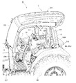
- the tractor A1 as a work vehicle is centered on a body frame 1 in which a longitudinal steel plate extending in the front-rear direction is arranged in the vertical direction and arranged on the left and right. Is equipped with a prime mover section 2.
- a driving unit 3 is disposed behind the prime mover unit 2.
- Front and rear wheels FT, RT to which power is transmitted from the engine E via a mission case M are pivoted below the body frame 1.
- Mission case M is fixed to the fuselage frame 1 integrally.
- a PTO shaft (not shown) projects from the rear end of the mission case M.
- shaft is an axis
- the transmission case M is configured to be able to transmit power to various working machines connected to the rear part of the tractor A1 via a connector, a lifter or the like (not shown).
- a hydraulic continuously variable transmission, a forward / reverse switching mechanism, a sub-transmission gear mechanism, a two-wheel drive / four-wheel drive switching mechanism, a differential gear mechanism for rear wheels, and the like are provided.
- the tractor A1 is configured as a cabin-type tractor that covers the operation unit 3 with a cabin C.
- the tractor A1 is provided with a prime mover portion 2 at the front portion of the body frame 1 that is stretched in the front-rear direction to form a framework, and a transmission case M is provided at the rear end portion of the body frame 1. ing.
- the prime mover unit 2 and the transmission case M are linked to each other via a power transmission shaft (not shown).
- a front axle case FA having an axis line in the left-right direction is attached to the front portion of the body frame 1.
- Front wheels FT and FT are attached to the left and right ends of the front axle case FA via front wheel shafts (not shown).
- rear axle cases RA and RA are attached to the left and right sides of the transmission case M, respectively, and the rear wheels RT and RT are interlocked and connected to the rear axle cases RA and RA via the rear wheel shaft 4.
- the transmission case M and the front axle case FA are linked together via a front wheel drive shaft (not shown) to enable four-wheel drive for driving the front and rear wheels FT, RT.
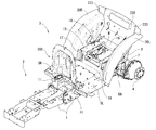
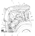
- the tractor A1 has a driving unit 3 disposed on the body frame 1 behind the prime mover unit 2. Specifically, the tractor A ⁇ b> 1 has the operation unit 3 mounted and fixed on the left and right base frames 5 attached to the sides of the body frame 1. The left and right base frames 5 have inclined frames 6 that are bent upward at the rear side. An auxiliary beam 8 is erected substantially vertically at a rear end portion of the left and right base frames 5 through a horizontal connecting plate 7 provided in association with the rear axle case RA.
- the left and right base frames 5 are mounted and fixed via vibration-proof sound plates 12 on a driving unit mounting piece 11 having a front end protruding from the side of the body frame 1.
- the lower end portion of the auxiliary beam 8 is placed and fixed via a shock absorber 218 having an anti-vibration sound plate 12 on the left and right rear axle cases RA and RA.
- the driving unit 3 has a driving unit floor 9 as a floor portion extending on the left and right base frames 5 from a position immediately after the prime mover unit 2 to a position immediately before the mission case M.
- a plan view type floor mounting plate 220 and a plan view rectangular floor reinforcing plate 221 are connected between the left and right base frames 5, and left and right steps SL configured by one piece on each of them.
- SR is placed and fixed, and a driving unit floor 9 is stretched over the upper side.
- the driver's seat frame 14 for constituting the driver's seat 13 is placed on and connected to the inclined frame 6 of the left and right base frames 5. That is, the driver's seat frame 14 includes a horizontal seat frame 15, a back frame 16 that is tilted up at the rear edge thereof, a front frame 17 that hangs below the front end of the seat frame 15, and a lower end of the front frame 17. And a dustproof plate 18 extending forward.
- the dust-proof plate 18 is connected to the rear edge of the driving unit floor 9 to block the lower part of the front end of the driver's seat frame 14 and prevent the dust rising from the ground through the space below the driver's seat 13 from entering the driving unit 3. is doing.
- a substantially triangular backing plate 19 that stands up and is in contact with the outer surface of the inclined frame 6 is in close contact with and fixed by bolts.
- a fender inner wall portion 21 of a fender 20 that covers the inner side of the rear wheel RT is inserted between the seat frame 15 and the contact plate 19 raised from the inclined frame 6 of the left and right base frames 5.
- the three members are firmly and integrally connected by bolts.
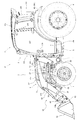
- the driver's seat 13 is disposed above the transmission case M located behind the engine E of the prime mover unit 2, and a pair of left and right fenders 20 ⁇ / b> L and 20 ⁇ / b> R are disposed on the left and right sides of the driver's seat 13.
- the pair of left and right fenders 20L and 20R are formed by being raised from the left and right sides of the rear portion of the driving unit floor 9, and cover the front upper portions of the rear wheels RT and RT.
- the pair of fenders 20L and 20R are extended with outer fenders 42L and 42R that cover the outer edges of the fenders 20L and 20R and extend outward.
- a front loader 50 as a work machine is detachably attached to the front portion of the body frame 1.
- the front loader 50 includes a pair of left and right masts 51 that are detachably attached to the body frame 1, a pair of left and right lift arms 52 that are connected to the mast 51 so as to be vertically rotatable, and a connection that connects the pair of left and right lift arms 52.
- Pipe 53 a pair of left and right work tool links 54, a pair of left and right work tool brackets 55, a work tool 56 attached to a pair of left and right lift arms 52, a pair of left and right arm cylinders 57, and a pair of left and right work tools A cylinder 58, a stand 59, and a front guard that protects the front portion of the tractor A1 are provided.
- the front loader 50 performs work by raising and lowering the work tool 56.
- a bucket is used as the work tool 56, but other work tools can be attached.
- a pair of left and right loader mounts 60 are respectively fixed to the outside of the left and right plate-like members constituting the machine body frame 1.
- a pair of left and right masts 51 are detachably attached to the pair of left and right loader mounts 60.
- the lift arm 52 is configured to have a boomerang-like shape in a side view of the machine body by a rear lift arm 52 a attached to the mast 51 and a front lift arm 52 b attached to the work tool 56.
- the rear lift arm 52a and the front lift arm 52b are fixed to each other by welding so as to form a predetermined angle.
- the rear ends of the left and right lift arms 52 are pivotally supported by pivot shafts 61 at the upper end of the mast 51, respectively.
- the front loader 50 is configured such that the front portion can be turned up and down around the pair of left and right pivot shafts 61.
- a front end portion (rear end) of the piston rod of the arm cylinder 57 is pivotally supported at the front end portion of the mast 51 in the middle of the upper and lower parts, and an arm cylinder bracket portion below the front end portion of the rear lift arm 52a includes A base end portion (front end) of the arm cylinder 57 is pivotally supported.
- the pair of left and right arm cylinders 57 serve as an actuator for turning the front loader 50 up and down, and by the simultaneous expansion and contraction of the piston rods of the left and right arm cylinders 57, the vertical turning angle of the front loader 50, that is, The angle of the pair of left and right lift arms 52 with respect to the mast 51 is adjusted.
- the left and right front lift arms 52b are integrally fixed by connecting the front and rear intermediate portions thereof with each other by a connection pipe 53 whose longitudinal direction is the body width direction.
- the front end of the front lift arm 52 b is attached to the work tool 56 via the work tool bracket 55.
- the work tool bracket 55 pivotally supports the front end of the front lift arm 52b. Thereby, the work tool bracket 55 and the work tool 56 can be rotated up and down with respect to the pair of left and right lift arms 52.
- Each work tool link 54 includes an arm side link member 54a and a work tool side link member 54b.
- the lower end of the arm side link member 54a is pivotally supported by the front and rear midway part of the front lift arm 52b.
- the lower end of the work tool side link member 54 b is pivotally supported on the upper part of the work tool bracket 55.
- a work tool cylinder 58 is attached above the front end of the lift arm 52.
- the upper ends of the arm-side link member 54a and the work tool-side link member 54b pivotally support the tip of the piston rod of the work tool cylinder 58.
- the base end portion of the work tool cylinder 58 is pivotally supported above the front end portion of the rear lift arm 52a.
- the pair of left and right work tool cylinders 58 serves as actuators for pivoting the work tool bracket 55 back and forth.
- the angle formed by the arm side link member 54a and the work tool side link member 54b is adjusted, the front / rear rotation angle of the work tool bracket 55 with respect to the lift arm 52 is adjusted, and the rotation angle of the work tool 56 is adjusted.
- the hydraulic operation unit 30 for switching the operation (not shown), other operation levers 330 and 332, and switches 331 are provided.
- a hot air shielding plate 200 that shields the prime mover unit 2 and the operating unit 3 is erected on the front edge of the operating unit floor 9.
- a connecting case 27 protrudes from the hot air shielding plate 200 on the side of the operating unit 3, and is further attached to a steering column 24 attached to a steering bracket 28 fixed to the connecting case 27 in a tiltable manner via a handle support shaft 26. H is provided.
- the dashboard 25 is attached to the upper edge of the hot air shielding plate 200 at the front upper side of the steering column 24, and the steering mechanism 22 is covered with a steering cover 43 except for the steering wheel H.
- An accelerator lever 65 for setting and maintaining the rotational speed of the engine E is provided on the right side of the steering cover 43.
- the various operation pedals 23 are supported by a connection case 27 protruding from the hot air shielding plate 200, and a clutch pedal CP, a left brake pedal LBP, and a right brake pedal RBP are arranged from the left.
- An accelerator pedal AP projects from the right step SR that constitutes the floor surface.
- the accelerator pedal AP functions as an accelerator-linked main transmission pedal that controls the rotational speed of the engine E or the vehicle speed.
- a potentiometer (variable resistor) type pedal sensor for detecting the vertical movement of the accelerator pedal AP is fixed below the right step SR.
- the floor surface is a generally flat surface.
- a driver seat 13 having left and right armrests 300L and 300R is placed on the horizontal seat frame 15 formed on the driver seat frame 14, as shown in FIGS. 10 and 11.
- the loader operation unit 29, the hydraulic operation unit 30, other various operation levers 330 and 332, and switches 331 are intensively arranged, and are easy for the driver to operate.
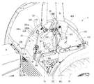
- the cabin C includes a cabin frame 222 that is framed so as to form a hexahedron, and respective surface portions 223, 225, which are formed by pieces that form the cabin frame 222. 231 and 236.
- the cabin frame 222 has a ceiling portion 224 formed in a flat box shape on the ceiling surface portion 223, a front glass portion 226 is stretched on the upper portion of the front portion 225, and a left and right front wall portion 227 is formed on the lower portion. It is stretched.
- the hot air shielding plate 200 constitutes a part of the front portion 225 of the cabin C. That is, the front portion 225 is configured by the hot air shielding plate 200, the left and right front wall portions 227 that are stretched on the left and right sides of the hot air shielding plate 200, and the windshield portion 226 that is stretched on the hot air shielding plate 200.
- the rear surface portion 231 has the upper end of the auxiliary beam 8 connected integrally with the rear end of the fender 20 and the rear lower end of the cabin frame 222 via the connection bracket 233.
- the rear lateral frame 232 provided in the middle stage of the rear surface of the cabin frame 222 is integrally connected to the back frame 16 of the driver's seat frame 14 by bolts.
- the front lower end edge of the cabin frame 222 that is, the horizontal lower frame 235 in front of the semicircular frame 234 placed on the fender 20, is in contact with the outer edge of step S as shown in FIGS. They are in contact with each other.
- a pair of left and right entrance / exit door portions 237 and 237 are stretched on the front portion of the left and right side surface portions 236 so as to be freely opened and closed. As shown in FIG. 11, an opening / closing operation grip 239 is provided outside the passenger door portion 237. A grip pipe 238 is stretched on the inner surface of the passenger door 237.
- a pair of left and right side window portions 240 are stretched on the rear portion of the left and right side surface portions 236 so as to be freely opened and closed.
- a rear glass portion 241 is stretched on the rear surface portion 231 so as to be freely opened and closed.
- the prime mover section 2 is configured by disposing an engine E or the like at the front of the body frame 1.
- a cooling fan 31 and a radiator 32 are erected immediately in front of the engine E.
- the motor unit 2 configured as described above is provided with a bonnet support frame (not shown), and the bonnet B is attached to the bonnet support frame so as to be opened and closed.
- the engine room of the motor unit 2 is covered with the bonnet B. It is open.
- the bonnet B is a box that opens downward and rearward from a ceiling surface portion 33 formed in an inverted shape (so-called ship bottom ceiling), a mesh-shaped front grille 34, and left and right side surface portions 35, 35. It is formed into a mold.
- an exhaust heat cover 37 having an exhaust heat hole 38 is formed in the gap 36 formed between the bonnet B covering the prime mover unit 2 configured as described above and the operating unit 3. Is installed.
- the exhaust heat cover 37 is connected to the upper portion of the hot air shielding plate 200.
- the tractor A1 according to the embodiment of the present invention has the basic structure as described above.
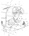
- the operating unit 3 of the tractor A1 has the following configuration. That is, in the tractor driving section 3 in which the driver's seat 13 is disposed behind the steering wheel H and the loader operating section 29 and the hydraulic operating section 30 are disposed in the vicinity of the driver's seat 13, as shown in FIG.
- the loader operation unit 29 and the hydraulic operation unit 30 are arranged in the range of the semicircular rotation of the right arm around the driver's right elbow on the armrest 300R.
- the loader operation unit 29 and the hydraulic operation unit 30 move the right elbow attached to the armrest 300R in a state where the driver sitting in the driver's seat 13 places the right elbow at a predetermined position on the armrest 300R. And is provided within a range that can be operated with the right hand.
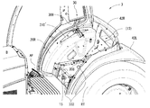
- the hydraulic operation bracket 310 which is a bracket of the hydraulic operation unit 30 is fixed to the fender outer peripheral surface 302 of the fender 20 protruding in the cabin C that houses the operation unit 3 as shown in FIG.
- the fender outer peripheral surface 302 of the fender 20, the hydraulic operation bracket 310, and the loader operation bracket 307, which is a loader operation unit 29 bracket, are configured to be collectively covered with a guide body 303 that supports the operation units 29 and 30. It also has a feature.
- the driving unit 3 has a handle H in front of the driver's seat 13 and includes a display device (not shown) installed in the dashboard 25 in front of the handle H. .
- Various instruments are disposed in the display device.
- Various operation pedals 23 are arranged above the floor surface below the handle H.
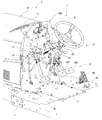
- fenders 20L and 20R As shown in FIG.
- a loader operation unit 29 for performing the lifting operation of the work implement On the right fender 20R, that is, on the fender outer peripheral surface 302 and in the vicinity thereof, a loader operation unit 29 for performing the lifting operation of the work implement, a hydraulic operation unit 30 for performing operations related to hydraulic pressure, and other operation levers 330 and 332 and switches 331 are disposed. Further, the loader operation unit 29 and the hydraulic operation unit 30 are disposed around the right armrest 300R so as to be positioned on the semicircular locus T in plan view (see FIG. 10).
- the loader operation section 29 and the hydraulic operation section 30 are arranged such that the height positions of the respective front end portions are slightly above the upper surface of the right armrest 300R and are substantially the same height position. Yes.
- the loader operation unit 29 is provided behind the accelerator pedal AP.
- the hydraulic operation unit 30 is provided behind the loader operation unit 29.
- the loader operation unit 29 includes a rod-shaped loader operation lever body 304 and a gripping unit including various operation switches (305a, 305b, 305c) capable of mode switching at the tip of the loader operation lever body 304. 306 and configured as an integral loader lever.
- a loader operation bracket 307 is fixed on the seat frame 15 located between the front right side of the driver seat 13 and the fender 20R, that is, between the driver seat 13 and the fender 20R.
- the loader operation bracket 307 is mainly composed of a rectangular plate-like member having an approximately L shape.
- the loader operation part 29 is erected so that the base part is connected to a loader operation bracket 307 and can be swung freely. Note that the loader operation unit 29 may be disposed on the outer peripheral surface of the right fender 20R.
- the loader operation unit 29 is a lever operation unit for switching a loader valve (not shown) for controlling supply of hydraulic oil to the hydraulic equipment of the front loader 50.
- the loader valve is provided on the side surface of the body frame 1 via a bracket or the like.
- a loader operation lever body 304 of the loader operation unit 29 is swingably supported by the loader operation bracket 307.
- the loader operation unit 29 is connected to the loader valve via push-pull wires 63 and 64 that are connected and fixed to the loader operation bracket 307 via a link member or the like.
- the tip of one push-pull wire 63 is connected to a link member for tilting left and right.
- the link member for tilting left and right is supported by the loader operation bracket 307 so as to be swingable in the left and right directions in accordance with the left and right tilting operation of the loader operation unit 29.
- the tip of the push-pull wire 63 moves up and down via the link member for tilting left and right.
- the tip of the other push-pull wire 64 is connected to a link member for tilting back and forth.
- the link member for forward / backward tilting is supported by the loader operation bracket 307 so as to be swingable in the front / rear direction in accordance with the forward / backward tilting operation of the loader operation unit 29.
- the tip of the push-pull wire 64 moves up and down via the link member for tilting back and forth.
- an operation lever 330 that is inserted from below a long hole 308 formed in the seat frame 15 with the front-rear direction as a longitudinal direction and protrudes upward is disposed.
- the operation lever 330 is a separate operation unit with a relatively high operation frequency.
- the height of the tip of the operation lever 330 is lower than the right armrest 300R as shown in FIGS.
- the operation lever 330 is a working part position lever that changes and adjusts the height position of a ground working machine such as a rotary tiller.
- a hydraulic operation unit 30 is disposed near the upper rear end of the fender 20R on the right side of the driver's seat 13.
- the hydraulic operation unit 30 is provided with three hydraulic operation levers (SCV levers) 309 for switching the hydraulic external take-off valve.
- Each hydraulic operation lever 309 is rod-shaped and has a grip at the tip.
- the three hydraulic operation levers 309 are disposed adjacent to the front and rear.
- the hydraulic external take-off valve is used to supply and control hydraulic oil to hydraulic equipment of a working machine such as a rotary tiller or a component caster that is retrofitted to the tractor A1.
- the number of hydraulic operation levers 309 is arranged according to the number of hydraulic external extraction valves. That is, in this embodiment, three hydraulic external take-off valves are provided.
- each hydraulic operation lever 309 is connected to a hydraulic operation bracket 310 as shown in FIG.
- the hydraulic operation bracket 310 is mainly composed of a rectangular plate-like member that is bent and fixed along the fender 20R on the fender outer peripheral surface 302 of the right fender 20R.
- Each hydraulic operation lever 309 disposed in the hydraulic operation unit 30 is connected to the hydraulic operation bracket 310 at its base and is erected so as to be operated.
- a switch 331 such as a mode changeover switch connected to a guide body 303 described later is disposed above the front portion of the hydraulic operation bracket 310.
- a PTO clutch switch 331a, a rotation speed / vehicle speed setting dial 331b, a rotation speed / vehicle speed selection switch 331c, and a vehicle speed sensitivity adjustment dial 331d are disposed as the switches 331 (see FIG. 12).
- the PTO clutch switch 331a is an operation unit for performing intermittent operation of power transmission from the PTO shaft to a work machine such as a rotary tiller.
- the rotation speed / vehicle speed setting dial 331b is an operation unit for presetting the maximum rotation speed of the engine E or the maximum traveling speed of the body frame 1.
- the rotational speed / vehicle speed selection switch 331c is an operation unit for designating whether the value set by the rotational speed / vehicle speed setting dial 331b is the maximum rotational speed of the engine E or the maximum traveling speed of the body frame 1.
- the vehicle speed sensitivity adjustment dial 331d is an operation unit for adjusting the acceleration / deceleration of the vehicle speed when the accelerator pedal AP is operated.
- an engine tilt switch 305a is provided on the front surface of the grip unit 306, and a valve operation switch 305b and a mode switch 305c are provided on the left side surface of the grip unit 306. Since the grip portion 306 is gripped by the operator's right hand, the engine tilt switch 305a is disposed at a position where it can be operated with an index finger or the like, and a valve operation switch 305b and a mode switch 305c are disposed at a position where the thumb can be operated. ing. Therefore, the operator can easily operate the switches 305a, 305b, and 305c while holding the loader operation unit 29 during the loader work by the front loader 50.
- the engine tilt switch 305a is used, for example, when a high load is applied during execution of a tilting operation using a front loader 50 or a dozer operation for scratching the ground.
- the engine rotation speed of the engine E is increased, while the gear ratio by the hydraulic continuously variable transmission is decreased to execute engine tilt control that keeps the vehicle speed of the tractor A1 constant.
- the engine tilt control is a case where the first speed and the second speed are designated among the sub-speeds that can be designated up to the third speed by the sub-shift lever, and the mode change control by the mode change switch 305c is not executed. It is executed while the engine tilt switch 305a is pressed.
- the operator determines that the work is a high load operation based on hearing and vision during the loader operation by the front loader 50, and simultaneously operates the loader operation unit 29.
- the engine tilt control is easily executed with the hand (right hand in this embodiment).
- the hydraulic lift for the arm cylinder 57 and the work tool cylinder 58 can be increased instantaneously according to the operator's judgment, so that the complexity of operating the work machine such as the front loader 50 can be increased.
- the load on the work machine can be reduced.
- the valve operation switch 305b is a hydraulic cylinder other than the arm cylinder 57 and the work tool cylinder 58. Used in the configuration provided in the work tool 56.
- the bale grab cylinder in the bale grab serving as the work tool 56 expands and contracts, and the pasture roll can be held or released.
- the arm cylinder 57 is operated by the forward / backward tilting operation of the loader operation unit 29 and the work tool 56 is moved up and down, and the work tool cylinder 58 is operated by the left / right tilting operation of the loader operation unit 29 to perform work.
- the bale grab serving as the tool 56 is tilted up and down, and the valve operation switch 305b of the loader operation unit 29 is operated to operate the bale grab cylinder to open and close the bale grab serving as the work tool 56.
- the mode switch 305c is used when switching between the maximum rotation speed and the maximum speed set in advance for a plurality of modes. Although the present embodiment will be described as the case of the two modes of the first mode and the second mode, it is possible that settings of three or more modes can be executed.
- the maximum rotation speed and the maximum vehicle speed in the first and second modes are set by operating the rotation speed / vehicle speed setting dial 331b and the rotation speed / vehicle speed selection switch 331c serving as a rotation speed / vehicle speed setting operation tool. Note that the rotational speed of the engine E and the vehicle speed of the tractor A1 at the maximum positions of the accelerator lever 65 and the accelerator pedal AP are set as the maximum rotational speed and the maximum vehicle speed set in the first and second modes, respectively.
- the mode switching switch 305c By operating the mode switching switch 305c, switching between the first mode and the second mode is executed, and the maximum rotation speed and the maximum vehicle speed in the first and second modes are switched according to the operation to the mode switching switch 305c. .
- the maximum rotation speed and the maximum vehicle speed in the second mode are set to be smaller than the maximum rotation speed and the maximum vehicle speed in the first mode.
- the mode changeover switch 305c is operated to set the second.
- the tractor A1 is moved at a low speed, so that the object to be transported can be prevented from dropping.
- the mode changeover switch 305c is operated to switch to the first mode, so that the tractor A1 is moved at a high speed, so the travel time from the carry-out destination to the carry-in source is shortened. It is possible to improve work efficiency.
- the operator By disposing the mode changeover switch 305c in the loader operation unit 29, the operator operates the loader operation unit 29 based on the presence or absence of the object to be transported during the transport operation by the front loader 50 (this embodiment). In the right hand), the moving speed of the tractor A1 is easily switched. Therefore, when the transport object is transported by the front loader 50, the transport object can be prevented from falling, and the travel time can be shortened when the transport object is moved after the transport is completed, so that the work efficiency can be improved.
- accelerator interlock control is performed as operation control related to the accelerator pedal AP.
- accelerator-linked control the vehicle speed when only the accelerator pedal AP is at the maximum position is set as the maximum vehicle speed set for each mode.
- accelerator interlocking control is not executed, the vehicle speed when the accelerator pedal AP and the accelerator lever 65 are set to the maximum positions is set as the maximum vehicle speed set for each mode.
- the vehicle speed of the tractor A1 is changed according to the depression amount of the accelerator pedal AP, and the rotation speed of the engine E is changed from the minimum rotation speed set by the accelerator lever 65.
- the rotation speed of the engine E increases and the vehicle speed of the tractor A1 increases.
- the accelerator interlocking control is not executed, the tractor A1 is kept in a state where the rotational speed of the engine E is kept constant at the minimum rotational speed set by the accelerator lever 65 according to the depression amount of the accelerator pedal AP. The vehicle speed changes.
- the switch for executing the accelerator interlocking control is disposed on the upper surface of the steering column 24, for example.
- the various operation units such as the loader operation unit 29 and the hydraulic operation unit 30 arranged as described above include the brackets 307 and 310 and the fender 20R exposed to the operation unit 3 in FIG.
- the guide body 303 shown is collectively covered.
- the guide body 303 is colored differently from the peripheral member adjacent to the guide body 303. Thereby, it is easy to visually recognize that the region where various operation units such as the loader operation unit 29 and the hydraulic operation unit 30 are disposed is a region where an operation different from the handle H operation is performed.
- an operating lever 332 that is inserted from below 315 and protrudes upward is provided.
- the operation lever 332 is a separate operation unit that is less frequently operated.
- an auxiliary transmission lever that switches the output range of the traveling auxiliary transmission gear mechanism provided in the transmission case M, and a four-wheel drive lever that switches between the two-wheel drive and the four-wheel drive of the front and rear wheels FT, RT are arranged.
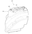
- the guide body 303 is formed in a concave substantially curved shape with the lower side as the open side, and a part of the upper part and the side part of the fender 20R of the fender 20R are located upward. It is a member that can be covered.
- a loader operation lever insertion hole 318 that penetrates the loader operation lever body 304 of the loader operation section 29 is formed so as to penetrate therethrough. That is, in the guide body 303, the portion where the loader operation lever insertion hole 318 is formed is a portion that is erected upward from the floor surface of the operation unit floor 9 and has an opening in the upper and lower ends. Forming.
- a rectangular box-shaped switch mounting portion 319 is installed in the middle of the upper portion of the guide body 303 so as to operably mount various switches 331 and the like to cover the mechanism portion.
- a plurality of switch attachment holes 320 are formed in the switch attachment portion 319 so that each operation portion of the switch 331 is exposed from the surface.
- a hydraulic operation lever insertion elongated hole 321 for inserting the hydraulic operation lever 309 of the hydraulic operation unit 30 is formed on the upper rear end side of the guide body 303.
- the hydraulic operation lever insertion long hole 321 is formed such that its longitudinal direction forms an inclination angle of about 45 ° with respect to the front-rear direction in plan view and is obliquely forward from the inner side to the outer side in the vehicle left-right direction.
- the three hydraulic operation lever insertion long holes 321 are formed in parallel to each other adjacent to the front and rear.
- a lever insertion long hole 322 for inserting the operation lever 330 is formed in the middle portion of the side portion of the guide body 303.
- the lever insertion long hole 322 is a guide hole whose longitudinal direction is the front-rear direction in plan view.
- the lever insertion long hole 322 is formed at a position lower than the loader operation lever insertion hole 318, the switch attachment hole 320, and the hydraulic operation lever insertion long hole 321 described above.
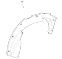
- the guide body 303 of the present embodiment is formed as described above, the exposed portion of the fender 20R that is not covered with the guide body 303 may be covered with a separate fender cover (not shown).
- the loader operation unit 29 is positioned slightly to the right in front of the right armrest 300R in plan view.
- the hydraulic operation unit 30 is located on the right side of the right armrest 300R in a plan view so as to be curved outward from the middle part to the rear end part of the right armrest 300R.
- the locus in plan view connecting the loader operation portion 29 and the hydraulic operation portion 30 is located on the semicircular locus L as shown in FIG. Specifically, the arcuate trajectory (T) in plan view passes through the operation movement range of the loader lever as the loader operation unit 29 and the operation movement range of each hydraulic operation lever 309 of the hydraulic operation unit 30. In this way, the loader operation unit 29 and the hydraulic operation unit 30 are arranged so that any operation position in the operation movement range of each operation unit (lever) is positioned on the arcuate trajectory (T) in plan view. Has been.
- a loader operation unit 29 is provided substantially in front of the right armrest 300R (see arrow D1), and the hydraulic operation unit 30 is located in a direction substantially perpendicular to the right direction (see arrow D2). Is provided.
- An operation lever having substantially the same height as that of the loader operation unit 29 or the like is not provided in the 45 ° diagonally right area of the right armrest 300R. Switches 331 are provided.
- the separate operation lever 330 having a relatively high operation frequency disposed in the 45 ° diagonally right region of the right armrest 300R where the loader operation unit 29 and the hydraulic operation unit 30 are not located has a tip portion height.
- the operation units 29 and 30 are clearly separated in terms of arrangement, including the fact that the operation units 29 and 30 are clearly lower than the operation units 29 and 30.
- the tractor A1 includes an accelerator-linked accelerator pedal AP that controls the rotational speed or the vehicle speed of the engine E, and the loader operation unit 29 is provided behind the accelerator pedal AP.
- the rotational speed or the vehicle speed of the engine E is controlled by the pedal operation of the accelerator pedal AP without providing a manually operated operation member such as a main transmission lever as an operation member for main transmission. Is possible.
- the operation object by manual operation can be reduced, the workability at the time of operation of the loader operation unit 29 can be improved, and the work burden on the driver when operating the loader operation unit 29 is reduced. be able to.
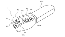
- the loader operation unit 29 can be disposed at the tip of the right armrest 300R ′ as in the modification examples shown in FIGS.
- the loader operation portion 29 of this modification can be tilted forward and backward at the distal end portion of the lever support portion 401 extending integrally forward with the right armrest 300R ′ on the distal end side of the right armrest 300R ′.
- the loader operation lever body 402 is supported by the robot.
- the lever support portion 401 includes support side wall portions 401a that face each other in the left-right direction.
- a loader operation lever body 402 is supported between the left and right support side wall portions 401a with the left-right direction as the rotation axis direction.
- the loader operation lever body 402 extends upward (in detail, obliquely forward upward) from the front end portion of the lever support portion 401.
- the loader operation unit 29 is connected to the loader valve via the two push-pull wires.
- rotation operation switches 403 and 404 for rotating the work tool 56 of the front loader 50 are provided at two locations along the longitudinal direction of the loader operation lever body 402. It has been.
- the rotation operation switches 403 and 404 are button-type switches that are pressed. By pressing the upper rotation operation switch 403, the work tool 56 is rotated to one side (upward), and by pressing the lower rotation operation switch 404, the work tool 56 is moved to the other side (lower). To turn.
- the arm valve in the loader valve acts when one of the two push-pull wires pushes and pulls in response to the forward / backward tilting operation of the loader operation lever body 402.
- the arm cylinder 57 is extended and retracted, the left and right lift arms 52 are turned up and down, and the work tool 56 is moved up and down.
- the other push-pull wire of the two push-pull wires pushes and pulls in response to the pressing operation of any one of the rotation operation switches 403 and 404 on the side surface of the loader operation lever body 402, so that the loader The work implement valve in the valve acts.
- the work tool cylinder 58 is extended and retracted in the front loader 50 and the work tool 56 is rotated.
- a lifting lever 405 for finely adjusting the lifting / lowering of the work tool 56 with respect to the lifting / lowering operation of the work tool 56 of the front loader 50 is projected.
- the elevating lever 405 is a knob type lever that moves up and down with respect to the loader operation lever body 402. By moving the lifting lever 405 upward, the work tool 56 is moved up by a small amount by the operation of the arm cylinder 57, and by moving the lifting lever 405 downward, the work tool 56 is moved by the operation of the arm cylinder 57. Decrease by small amount.
- a switch disposition surface portion 401b is provided behind the loader operation lever body 402 in the lever support portion 401, and switches 406 are disposed on the switch disposition surface portion 401b.
- switches 406 for example, the above-described rotation speed / vehicle speed setting dial, rotation speed / vehicle speed selection switch, and the like are arranged.
- the loader operation unit 29 is substantially in front of the right armrest 300R ′ (see arrow D1), and the hydraulic operation unit 30 is also substantially perpendicular to the right direction of the armrest 300R ′. Is disposed at a position in a direction (see arrow D2).
- the hydraulic operation lever 309 of the hydraulic operation unit 30 is composed of two, but the number of hydraulic operation levers 309 is a number that matches the number of hydraulic external take-off valves as described above. It is not limited to this embodiment.
- FIG. 19 shows a state in which the hydraulic operation lever 309 is erected on the fender 20R via the hydraulic operation bracket 310 ′ according to this modification
- FIG. 20 shows the guide body 303 ′ according to this modification
- FIG. 21 shows a cover body 334 for covering the exposed portion of the fender 20R that is not covered with the guide body 303 ′
- FIG. 22 shows a state in which a part of the fender 20R is covered with the cover body 334.
- the tractor A1 has a driver's seat 13 behind the steering wheel H and a driver 3 having a loader operating portion 29 and a hydraulic operating portion 30 in the vicinity of the driver's seat 13.
- the loader operation unit 29 and the hydraulic operation unit 30 are disposed within the range of the semicircular rotation of the right arm around the right elbow of the driver with the elbow on the armrest 300R on the right side of the driver's seat 13. Is provided.
- the loader operation unit 29, the hydraulic operation unit 30, and the handle H can be reliably gripped with different hands, and the operation of the tractor A1 and operation of the work machine such as towing can be performed. It can be done clearly in parallel. For this reason, not only can the workability be improved, but also the loader operation unit 29 and the like can be operated with the right elbow placed on the armrest 300R, so that the fatigue during the work can be greatly reduced. Can do.
- an operation unit other than the loader operation unit 29 and the hydraulic operation unit 30 can be arranged within the range of the semicircular arc rotation of the right arm, the workability can be further improved.
- the hydraulic operation bracket 310 that is a bracket of the hydraulic operation unit 30 is fixed to the fender outer peripheral surface 302 of the fender 20 protruding in the cabin C that houses the operation unit 3.
- the tractor A1 is configured to collectively cover the fender outer peripheral surface 302 of the fender 20R and the brackets 307 and 310 of the operation units 29 and 30 with a guide body 303 that supports the operation units 29 and 30. ing.
- the loader operation unit 29 and the hydraulic operation unit 30 can be collectively covered with the guide body 303 without covering the brackets 307 and 310 with separate members, the assembly workability can be improved and the manufacturing cost can be improved. Can be kept low.
- the loader operation bracket 307 and the hydraulic operation bracket 310 corresponding to the loader operation unit 29 and the hydraulic operation unit 30 are provided, and the hydraulic operation bracket 310 is fixed to the fender outer peripheral surface 302.
- a configuration in which the brackets 307 and 310 and the fender outer peripheral surface 302 are collectively covered with a guide body 303 is employed.
- the covering configuration by the guide body 303 is not limited to the above configuration, and one of the loader operation bracket 307 and the hydraulic operation bracket 310, for example, as shown in a modified example.
- a configuration in which the guide body 303 and the fender outer peripheral surface 302 are collectively covered may be employed.
Landscapes
- Engineering & Computer Science (AREA)
- Chemical & Material Sciences (AREA)
- Combustion & Propulsion (AREA)
- Transportation (AREA)
- Mechanical Engineering (AREA)
- Mining & Mineral Resources (AREA)
- Civil Engineering (AREA)
- General Engineering & Computer Science (AREA)
- Structural Engineering (AREA)
- General Physics & Mathematics (AREA)
- Automation & Control Theory (AREA)
- Physics & Mathematics (AREA)
- Lifting Devices For Agricultural Implements (AREA)
- Motor Power Transmission Devices (AREA)
- Retarders (AREA)
- Mechanical Control Devices (AREA)
- Component Parts Of Construction Machinery (AREA)
- Body Structure For Vehicles (AREA)
Abstract
L'invention concerne un tracteur, dans lequel tracteur différentes unités d'actionnement principales sont disposées sur le côté droit du conducteur, de façon à permettre ainsi aux unités d'actionnement et au volant de direction d'être saisis de façon fiable par des mains différentes et à la maniabilité d'être améliorée pour le conducteur, et dans lequel les unités d'actionnement principales sont disposées à l'intérieur de la plage sur laquelle le bras droit du conducteur tourne en un arc semi-circulaire autour du coude droit, qui repose sur un accoudoir, de telle sorte que la capacité d'actionnement pour le conducteur peut être améliorée et qu'une fatigue du conducteur peut être soulagée. Un tracteur comporte une section de conduite comprenant une unité d'actionnement de chargeur et une unité d'actionnement hydraulique disposée à proximité d'un siège de conducteur qui est disposé derrière le volant de direction, l'unité d'actionnement de chargeur et l'unité d'actionnement hydraulique étant disposées à l'intérieur de la plage sur laquelle le bras droit du conducteur tourne en un arc semi-circulaire autour du coude droit, qui repose sur l'accoudoir sur le côté droit du siège de conducteur.
Priority Applications (3)
| Application Number | Priority Date | Filing Date | Title |
|---|---|---|---|
| EP16821063.1A EP3321153B1 (fr) | 2015-07-07 | 2016-03-22 | Tracteur |
| JP2016544174A JP6293289B2 (ja) | 2015-07-07 | 2016-03-22 | トラクタ |
| US15/741,997 US10940901B2 (en) | 2015-07-07 | 2016-03-22 | Tractor |
Applications Claiming Priority (2)
| Application Number | Priority Date | Filing Date | Title |
|---|---|---|---|
| JP2015-135986 | 2015-07-07 | ||
| JP2015135986 | 2015-07-07 |
Publications (1)
| Publication Number | Publication Date |
|---|---|
| WO2017006592A1 true WO2017006592A1 (fr) | 2017-01-12 |
Family
ID=57685376
Family Applications (1)
| Application Number | Title | Priority Date | Filing Date |
|---|---|---|---|
| PCT/JP2016/059064 Ceased WO2017006592A1 (fr) | 2015-07-07 | 2016-03-22 | Tracteur |
Country Status (4)
| Country | Link |
|---|---|
| US (1) | US10940901B2 (fr) |
| EP (1) | EP3321153B1 (fr) |
| JP (1) | JP6293289B2 (fr) |
| WO (1) | WO2017006592A1 (fr) |
Cited By (1)
| Publication number | Priority date | Publication date | Assignee | Title |
|---|---|---|---|---|
| JP2020001435A (ja) * | 2018-06-25 | 2020-01-09 | 株式会社クボタ | 作業車両 |
Families Citing this family (3)
| Publication number | Priority date | Publication date | Assignee | Title |
|---|---|---|---|---|
| JP6971773B2 (ja) * | 2017-10-20 | 2021-11-24 | 株式会社小松製作所 | 作業車両のキャブ、作業車両およびホイールローダ |
| WO2020003948A1 (fr) * | 2018-06-29 | 2020-01-02 | 株式会社クボタ | Machine de travail |
| CN119243799B (zh) * | 2024-11-20 | 2025-11-14 | 徐州徐工筑路机械有限公司 | 一种平地机前轮转向装置及控制方法 |
Citations (4)
| Publication number | Priority date | Publication date | Assignee | Title |
|---|---|---|---|---|
| JP2014166815A (ja) * | 2013-02-28 | 2014-09-11 | Iseki & Co Ltd | 作業車 |
| JP2015009594A (ja) * | 2013-06-27 | 2015-01-19 | 三菱農機株式会社 | 作業車両 |
| JP2015042140A (ja) * | 2013-08-26 | 2015-03-05 | 三菱農機株式会社 | 作業車両 |
| JP2016041565A (ja) * | 2014-08-19 | 2016-03-31 | 株式会社クボタ | 操作制御システム |
Family Cites Families (17)
| Publication number | Priority date | Publication date | Assignee | Title |
|---|---|---|---|---|
| CA1336203C (fr) | 1988-07-27 | 1995-07-04 | Joseph M. Mather | Systeme hydraulique auxiliaire a commande electrique pour chargeur a direction differentielle |
| US7159684B2 (en) * | 2002-11-27 | 2007-01-09 | Clark Equipment Company | Interlock control system on wheeled work machine |
| JP2007032651A (ja) | 2005-07-25 | 2007-02-08 | Yanmar Co Ltd | 作業車両の制御装置 |
| JP2008025161A (ja) * | 2006-07-19 | 2008-02-07 | Kubota Corp | 作業車 |
| JP4934401B2 (ja) * | 2006-10-25 | 2012-05-16 | ヤンマー株式会社 | キャビン付作業車両 |
| JP4648918B2 (ja) * | 2007-03-30 | 2011-03-09 | 株式会社クボタ | トラクタ |
| JP2009274474A (ja) | 2008-05-12 | 2009-11-26 | Hitachi Constr Mach Co Ltd | 解体機 |
| JP5427100B2 (ja) | 2010-04-27 | 2014-02-26 | 株式会社クボタ | トラクタ |
| JP5313975B2 (ja) | 2010-08-10 | 2013-10-09 | 株式会社クボタ | 切換操作装置 |
| JP5736144B2 (ja) | 2010-10-22 | 2015-06-17 | ヤンマー株式会社 | トラクタにおける運転操作装置 |
| JP5802409B2 (ja) * | 2011-03-10 | 2015-10-28 | ヤンマー株式会社 | 農業用トラクタ |
| JP5835154B2 (ja) * | 2012-08-21 | 2015-12-24 | 井関農機株式会社 | 作業車 |
| JP6045073B2 (ja) | 2013-08-09 | 2016-12-14 | ヤンマー株式会社 | 作業車両 |
| EP3032371B1 (fr) * | 2013-08-09 | 2024-09-11 | Yanmar Power Technology Co., Ltd. | Véhicule de travail |
| JP6324872B2 (ja) * | 2014-10-16 | 2018-05-16 | ヤンマー株式会社 | 作業車両 |
| CN106489007A (zh) * | 2015-06-08 | 2017-03-08 | 株式会社小松制作所 | 驾驶室以及推土机 |
| US10480156B2 (en) * | 2015-12-14 | 2019-11-19 | Kubota Corporation | Work vehicle |
-
2016
- 2016-03-22 WO PCT/JP2016/059064 patent/WO2017006592A1/fr not_active Ceased
- 2016-03-22 US US15/741,997 patent/US10940901B2/en active Active
- 2016-03-22 JP JP2016544174A patent/JP6293289B2/ja active Active
- 2016-03-22 EP EP16821063.1A patent/EP3321153B1/fr active Active
Patent Citations (4)
| Publication number | Priority date | Publication date | Assignee | Title |
|---|---|---|---|---|
| JP2014166815A (ja) * | 2013-02-28 | 2014-09-11 | Iseki & Co Ltd | 作業車 |
| JP2015009594A (ja) * | 2013-06-27 | 2015-01-19 | 三菱農機株式会社 | 作業車両 |
| JP2015042140A (ja) * | 2013-08-26 | 2015-03-05 | 三菱農機株式会社 | 作業車両 |
| JP2016041565A (ja) * | 2014-08-19 | 2016-03-31 | 株式会社クボタ | 操作制御システム |
Non-Patent Citations (1)
| Title |
|---|
| See also references of EP3321153A4 * |
Cited By (1)
| Publication number | Priority date | Publication date | Assignee | Title |
|---|---|---|---|---|
| JP2020001435A (ja) * | 2018-06-25 | 2020-01-09 | 株式会社クボタ | 作業車両 |
Also Published As
| Publication number | Publication date |
|---|---|
| JPWO2017006592A1 (ja) | 2017-07-06 |
| EP3321153A1 (fr) | 2018-05-16 |
| EP3321153B1 (fr) | 2021-02-17 |
| US10940901B2 (en) | 2021-03-09 |
| EP3321153A4 (fr) | 2019-04-03 |
| JP6293289B2 (ja) | 2018-03-14 |
| US20180194408A1 (en) | 2018-07-12 |
Similar Documents
| Publication | Publication Date | Title |
|---|---|---|
| JP6293289B2 (ja) | トラクタ | |
| JPWO2017072937A1 (ja) | 作業車両 | |
| JP5569188B2 (ja) | 作業車両の無段変速操作装置 | |
| WO2022163294A1 (fr) | Mécanisme de direction et engin de chantier | |
| CN205100269U (zh) | 用于机器的辅助控制杆系统及操作员驾驶室 | |
| JP5776540B2 (ja) | 作業車両 | |
| EP4235354A2 (fr) | Dispositif de commande à distance et mécanisme de fonctionnement pour eingin de travail | |
| JP4429976B2 (ja) | ローダ操作装置 | |
| JP3987315B2 (ja) | 走行車両の操縦装置 | |
| JP2009035086A (ja) | 作業車両 | |
| JP3778374B2 (ja) | 作業機昇降装置 | |
| JP2024043073A (ja) | 作業車両 | |
| JP7816053B2 (ja) | 作業車両 | |
| JP4447516B2 (ja) | トラクタ | |
| JP2007313953A (ja) | 作業車両 | |
| EP3718808B1 (fr) | Mécanisme de fonctionnement de véhicule de travail et véhicule de travail | |
| JP2007092284A (ja) | 作業車 | |
| JP4364824B2 (ja) | トラクタ | |
| JP2693285B2 (ja) | 制御レバー装置 | |
| JP2595931Y2 (ja) | 移動農機の作業機昇降制御装置 | |
| JP3630156B2 (ja) | 作業機におけるローリング制御装置 | |
| JP3882976B2 (ja) | 田植機 | |
| JP2014008054A (ja) | 自走式作業車両 | |
| JP2005330726A (ja) | フロントローダの操作装置 | |
| JP2005137316A (ja) | 作業車 |
Legal Events
| Date | Code | Title | Description |
|---|---|---|---|
| ENP | Entry into the national phase |
Ref document number: 2016544174 Country of ref document: JP Kind code of ref document: A |
|
| 121 | Ep: the epo has been informed by wipo that ep was designated in this application |
Ref document number: 16821063 Country of ref document: EP Kind code of ref document: A1 |
|
| NENP | Non-entry into the national phase |
Ref country code: DE |
|
| WWE | Wipo information: entry into national phase |
Ref document number: 2016821063 Country of ref document: EP |