WO2017006647A1 - Structure de fixation pour un câble en matière plastique renforcée par des fibres, son procédé de fabrication, procédé d'essai de résistance et échantillon pour un essai de résistance - Google Patents
Structure de fixation pour un câble en matière plastique renforcée par des fibres, son procédé de fabrication, procédé d'essai de résistance et échantillon pour un essai de résistance Download PDFInfo
- Publication number
- WO2017006647A1 WO2017006647A1 PCT/JP2016/065928 JP2016065928W WO2017006647A1 WO 2017006647 A1 WO2017006647 A1 WO 2017006647A1 JP 2016065928 W JP2016065928 W JP 2016065928W WO 2017006647 A1 WO2017006647 A1 WO 2017006647A1
- Authority
- WO
- WIPO (PCT)
- Prior art keywords
- reinforced plastic
- strength test
- test
- fiber reinforced
- fiber
- Prior art date
- Legal status (The legal status is an assumption and is not a legal conclusion. Google has not performed a legal analysis and makes no representation as to the accuracy of the status listed.)
- Ceased
Links
Images






Classifications
-
- D—TEXTILES; PAPER
- D07—ROPES; CABLES OTHER THAN ELECTRIC
- D07B—ROPES OR CABLES IN GENERAL
- D07B1/00—Constructional features of ropes or cables
- D07B1/02—Ropes built-up from fibrous or filamentary material, e.g. of vegetable origin, of animal origin, regenerated cellulose, plastics
-
- E—FIXED CONSTRUCTIONS
- E01—CONSTRUCTION OF ROADS, RAILWAYS, OR BRIDGES
- E01D—CONSTRUCTION OF BRIDGES, ELEVATED ROADWAYS OR VIADUCTS; ASSEMBLY OF BRIDGES
- E01D19/00—Structural or constructional details of bridges
- E01D19/16—Suspension cables; Cable clamps for suspension cables ; Pre- or post-stressed cables
-
- E—FIXED CONSTRUCTIONS
- E04—BUILDING
- E04C—STRUCTURAL ELEMENTS; BUILDING MATERIALS
- E04C5/00—Reinforcing elements, e.g. for concrete; Auxiliary elements therefor
- E04C5/07—Reinforcing elements of material other than metal, e.g. of glass, of plastics, or not exclusively made of metal
-
- E—FIXED CONSTRUCTIONS
- E04—BUILDING
- E04C—STRUCTURAL ELEMENTS; BUILDING MATERIALS
- E04C5/00—Reinforcing elements, e.g. for concrete; Auxiliary elements therefor
- E04C5/08—Members specially adapted to be used in prestressed constructions
-
- G—PHYSICS
- G01—MEASURING; TESTING
- G01N—INVESTIGATING OR ANALYSING MATERIALS BY DETERMINING THEIR CHEMICAL OR PHYSICAL PROPERTIES
- G01N3/00—Investigating strength properties of solid materials by application of mechanical stress
Definitions
- the present invention relates to a fixing structure of a fiber reinforced plastic cable, a manufacturing method thereof, a strength test method, and a sample for strength test.
- Metal cables made of metal materials such as steel are used to support or reinforce structures such as bridges and buildings.
- the metal cable can be used as, for example, a bridge cable, a reinforcing cable for a building, various structures, tendons such as a ground anchor, and the like.
- FRP Fiber Reinforced Plastics
- FRP cables do not generate rust and are particularly useful for marine structure applications.
- Examples of the offshore structure include a tension mooring platform (TLP) used for offshore resource mining and offshore wind power generation.
- TLP tension mooring platform
- Patent Document 1 discloses a technique related to a fixing structure provided in an FRP cable.
- the fixing structure described in this document is formed of a metal material.
- the FRP cable with the fixing structure fixed is easily damaged in the vicinity of the fixing structure where the tension tends to concentrate. Therefore, a technique capable of effectively suppressing damage to the FRP cable is required.
- an object of the present invention is to provide a technique that can favorably hold the end portion of a fiber-reinforced plastic cable.
- a fixing structure for a fiber reinforced plastic cable is made of fiber reinforced plastic, and is provided at a longitudinal end portion of the fiber reinforced plastic cable. To an inclined portion whose diameter decreases toward the longitudinal center of the fiber-reinforced plastic cable.
- the fixing structure having this configuration is configured to be fixed to various structures or stable ground while the holding portion is held.
- the holding force applied to the holding part is transmitted to the fiber reinforced plastic cable through the fixing structure.
- the holding force is relaxed as the diameter decreases along the inclined portion when transmitted through the fixing structure. Therefore, the holding force applied to the fiber reinforced plastic cable from the fixing structure gradually decreases from the rear end portion of the inclined portion having a large diameter toward the tip portion having a small diameter.
- the tension of the fiber reinforced plastic cable provided with the fixing structure is first applied to the tip of the inclined portion of the fixing structure. Then, the inclined portion of the fixing structure is sequentially deformed from the front end portion having a weak holding force to disperse the tension toward the rear end portion.
- the tension of the fiber-reinforced plastic cable provided with the fixing structure is not concentrated locally but is distributed along the inclined portion. Therefore, the fiber reinforced plastic cable provided with the fixing structure is hardly damaged.
- the fixing structure may have a configuration in which a sheet-like fiber reinforced plastic is spirally wound.
- the fixing structure can be easily formed by winding a sheet-like fiber reinforced plastic.
- the sheet-like fiber reinforced plastic may have a configuration in which a fiber cloth is impregnated with plastic.
- particularly high strength can be obtained by using a sheet-like fiber reinforced plastic having a structure in which fiber cloth is impregnated with plastic.
- an uncured sheet of fiber reinforced plastic is prepared.
- the uncured sheet is spirally wound around the longitudinal end of the fiber reinforced plastic cable in a direction away from the longitudinal center of the fiber reinforced plastic cable.
- the uncured sheet wound around the fiber reinforced plastic cable is cured. In this configuration, a fixing structure that hardly damages the fiber reinforced plastic cable can be easily formed by winding an uncured sheet.
- a test piece of the fiber reinforced plastic cable is prepared.
- a holding structure having a holding portion and an inclined portion whose diameter decreases from the holding portion toward the central portion in the longitudinal direction of the test piece by fiber reinforced plastic at each of both longitudinal ends of the test piece.
- the strength test of the test piece is performed in a state where the holding portion of the holding structure provided on the test piece is held. In this configuration, the strength test of the test piece can be performed without breaking the test piece in the vicinity of the holding structure. Thereby, it becomes possible to evaluate the original exact strength of the fiber reinforced plastic cable.
- an uncured sheet of fiber reinforced plastic may be prepared.
- the uncured sheet is spirally wound around each end portion in the longitudinal direction of the test piece in a direction away from the longitudinal center portion of the test piece.
- the uncured sheet wound around the test piece is cured.
- the holding structure can be easily provided at both ends of the test piece.
- a sample for strength test of a fiber reinforced plastic cable includes a test piece of a fiber reinforced plastic cable and a holding structure.
- the holding structure is made of fiber reinforced plastic, provided at both ends of the test piece, a holding part, and an inclined part whose diameter decreases from the holding part toward the longitudinal center of the test piece, Have With this configuration, it is possible to provide a strength test sample capable of evaluating the strength of the test piece without breaking the test piece in the vicinity of the holding structure.
- the holding structure may have a configuration in which a sheet-like fiber reinforced plastic is wound spirally. In this configuration, a holding structure having an inclined portion can be easily formed by winding a sheet-like fiber reinforced plastic.
- the sheet-like fiber reinforced plastic may have a configuration in which a fiber cloth is impregnated with plastic.
- a holding structure having a particularly high strength can be obtained by using a sheet-like fiber-reinforced plastic having a structure in which fiber cloth is impregnated with plastic.
- FIG. 1 is a front view showing a fixing structure according to a first embodiment of the present invention.
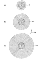
- FIG. 2 is a cross-sectional view taken along lines AA ′, BB ′, and CC ′ of FIG. 1 showing the fixing structure. It is a figure for demonstrating the retention strength added to an FRP cable from the said fixing structure.
- 3 is a flowchart showing a method for manufacturing the fixing structure.
- FIG. 6 is a front view showing an uncured sheet preparation step (step S1-1) of the method for manufacturing the fixing structure.
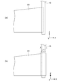
- FIG. 5 is a front view showing an uncured sheet winding step (step S1-2) of the method for manufacturing the fixing structure.
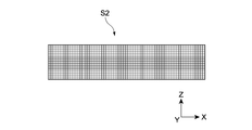
- FIG. 10 is a front view showing a modification of the uncured sheet preparation step (step S1-1) of the method for manufacturing the fixing structure.
- FIG. 10 is a front view showing a modification of the uncured sheet winding step (step S1-2) of the method for manufacturing the fixing structure.
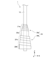
- FIG. 6 is a front view showing a first modification of the fixing structure.
- FIG. 9 is a perspective view showing a second modification of the fixing structure.
- FIG. 10 is a front view showing a third modification of the fixing structure.
- 10 is a flowchart showing a manufacturing method of Modification 3 of the fixing structure.
- FIG. 10 is a cross-sectional view showing a mold setting step (step S2-2) and a casting / curing step (step S2-3) of the manufacturing method of Modification 3 of the fixing structure.
- FIG. 1 is a front view showing a fixing structure 20 according to the first embodiment of the present invention.
- the fixing structure 20 is provided at each end of a fiber reinforced plastic (FRP: Fiber Reinforced Plastics) cable 10, and constitutes the FRP cable structure 1 together with the FRP cable 10. Since the fixing structures 20 at both ends of the FRP cable 10 have the same configuration, only the fixing structure 20 at one end will be described below, and the fixing structure 20 at the other end will be described. The description of is omitted.
- FRP Fiber Reinforced Plastics
- the fixing structure 20 can correspond to a wide variety of FRP cables 10, and the FRP cable 10 is not limited to a specific type.
- the FRP cable 10 for example, an FRP wire having a configuration in which a plurality of fiber materials extending along the longitudinal direction are bundled can be used. In this case, it is preferable that the plurality of fiber materials are continuously continuous in the longitudinal direction of the FRP cable 10.
- the fixing structure 20 includes a holding portion 22 disposed at an end portion in the Z-axis direction, and an inclined portion 21 having a diameter that decreases from the holding portion 22 toward the longitudinal center portion of the FRP cable 10.
- the inclined portion 21 has a substantially truncated cone shape, and the holding portion 22 has a substantially disk shape.
- the holding portion 22 and the largest diameter portion of the inclined portion 21 have the same diameter and are continuous.
- the fixing structure 20 is configured to be fixed to various structures or a stable ground via the holding device 2 in a state where the holding unit 22 is held by the holding device 2 (see FIG. 3).
- the FRP cable structure 1 provided with the fixing structure 20 can support or reinforce a structure such as a bridge or a building by the tension of the FRP cable 10.
- the FRP cable structure 1 can be used as, for example, a bridge cable, a reinforcing cable for a building, various structures, tendons such as a ground anchor, and the like.
- the fixing structure 20 is made of FRP. That is, the FRP cable 10 and the fixing structure 20 constituting the FRP cable structure 1 are both made of FRP. Therefore, since the FRP cable structure 1 is very lightweight as a whole, it contributes to improvement in workability. Moreover, since the FRP cable structure 1 does not generate rust, it is particularly useful for marine structures such as TLP.
- the FRP that constitutes the fixing structure 20 includes a resin component and a fiber material, and has a configuration in which the fiber material is impregnated with the resin component.
- the high-strength fixing structure 20 is realized by using an epoxy resin as a resin component and glass fiber as a fiber material.
- the resin component and the fiber material of the FRP constituting the fixing structure 20 are not limited to specific types.
- the resin component of the FRP that constitutes the fixing structure 20 may be a resin or an adhesive that has sufficient strength and can be satisfactorily adhered to the FRP cable 10, and is not limited to a specific type.
- the resin component of the FRP that constitutes the fixing structure 20 for example, vinyl ester resin, polyester resin, polyimide resin, polypropylene resin, polyamide resin, polycarbonate resin, and the like can be employed in addition to the epoxy resin.
- the FRP fiber material constituting the fixing structure 20 is not limited to a specific type as long as it can exhibit sufficient strength integrally with the resin component.
- a fiber material of FRP constituting the fixing structure 20 for example, carbon fiber, aramid fiber, boron fiber, or the like can be adopted in addition to glass fiber.
- the carbon fiber for example, a high-rigidity pitch-based carbon fiber, a high-strength PAN-based carbon fiber, or the like can be used.
- the fixing structure 20 has a configuration in which a sheet-like FRP (FRP sheet) is spirally wound around the FRP cable 10 downward in the Z-axis direction. That is, the upper end portion in the Z-axis direction of the FRP sheet is inclined by an angle ⁇ with respect to the XY plane, and extends spirally downward in the Z-axis direction. Thereby, the inclined part 21 whose diameter increases stepwise in the Z-axis direction downward is formed.
- FRP sheet sheet-like FRP
- FIG. 2 is a cross-sectional view showing the fixing structure 20. More specifically, FIG. 2A shows a cross section of the fixing structure 20 along the line AA ′ in FIG. 1, and FIG. 2B shows the fixing structure 20 along the line BB ′ in FIG. 2C shows a cross section taken along the line CC ′ of FIG. 1 of the fixing structure 20.
- FIG. 2A shows a cross section of the fixing structure 20 along the line AA ′ in FIG. 1
- FIG. 2B shows the fixing structure 20 along the line BB ′ in FIG. 2C shows a cross section taken along the line CC ′ of FIG. 1 of the fixing structure 20.
- FIG. 2A shows a cross section of the fixing structure 20 along the line AA ′ in FIG. 1
- FIG. 2B shows the fixing structure 20 along the line BB ′ in FIG. 2C shows a cross section taken along the line CC ′ of FIG. 1 of the fixing structure 20.
- FIG. 2A shows a cross section of the fixing structure 20 along the
- FIG. 2A shows a portion where the FRP sheet of the inclined portion 21 is wound twice
- FIG. 2B shows a portion where the FRP sheet of the inclined portion 21 is wound seven times
- FIG. ) Shows the holding unit 22.
- the holding portion 22 is a winding end portion of the FRP sheet, and is configured by an FRP sheet wound around 13 times.
- the winding number and angle ⁇ of the FRP sheet can be appropriately determined according to the type of the FRP cable 10 and the use of the FRP cable structure 1. Further, the winding direction of the FRP sheet in the fixing structure 20 may be left-handed as shown in FIG.
- the fiber material of the FRP sheet constituting the fixing structure 20 according to the present embodiment is configured as a fiber cloth in which long diameter fibers are two-dimensionally arranged. That is, this FRP sheet has a configuration in which a fiber cloth is impregnated with plastic. Thereby, the fixing structure 20 having particularly high strength is obtained.
- the fiber cloth may have a woven fabric structure such as plain weave, twill weave, and satin weave.
- the aspect of the fiber material of the FRP sheet is not limited to the fiber cloth.
- the fiber material of the FRP sheet may be, for example, a long diameter fiber oriented in the winding direction of the FRP sheet or a short diameter fiber dispersed in a random direction in the plastic.
- FIG. 3 is a view for explaining the holding force applied from the fixing structure 20 to the FRP cable 10. More specifically, the left diagram of FIG. 3 is a front view showing the fixing structure 20 in a state where the holding unit 22 is held by the holding device 2.
- the right diagram of FIG. 3 is a graph qualitatively showing the change in the holding force applied from the fixing structure 20 to the FRP cable 10 along the Z-axis direction.
- the horizontal axis represents the magnitude of the holding force
- the vertical axis represents the position in the Z-axis direction corresponding to the left diagram of FIG.
- the holding device 2 includes holding members 2a and 2b that face each other in the X-axis direction, and holds the fixing structure 20 by sandwiching a holding portion 22 of the fixing structure 20 between the holding members 2a and 2b. .
- the fixing structure 20 is fixed to various structures or stable ground via the holding device 2 in a state where the holding unit 22 is held by the holding device 2.
- the holding force applied to the holding unit 22 from the holding device 2 is transmitted to the FRP cable 10 through the fixing structure 20.
- the holding force is relaxed as the diameter decreases along the inclined portion 21 when transmitted through the fixing structure 20. Therefore, the holding force applied to the FRP cable 10 from the fixing structure 20 gradually decreases from the large-diameter rear end G of the inclined portion 21 toward the small-diameter front end F.
- the holding force applied from the fixing structure 20 to the FRP cable 10 is constant in the holding portion 22, but in the inclined portion 21, the large-diameter rear end portion G to the small-diameter tip portion. It gradually decreases toward F.
- the change along the Z-axis direction of the holding force in the inclination part 21 is linearly shown for convenience of explanation.
- the holding force in the inclined portion 21 only needs to monotonously decrease from the large-diameter rear end G toward the small-diameter front end F.
- the holding force in the inclined portion 21 is considered to change stepwise.
- the tension of the FRP cable 10 provided with the fixing structure 20 is applied to the small-diameter tip F of the inclined portion 21 of the fixing structure 20. Then, the inclined portion 21 of the fixing structure 20 is deformed sequentially from the front end F having a weak holding force, thereby dispersing the tension toward the rear end G.
- the tension of the FRP cable 10 provided with the fixing structure 20 is dispersed along the inclined portion 21 without being concentrated in the vicinity of the front end portion F of the inclined portion 21. Therefore, the FRP cable 10 provided with the fixing structure 20 is not easily damaged in the vicinity of the front end portion F of the inclined portion 21.
- the tension of the FRP cable 10 is dispersed according to the degree of change along the Z-axis direction of the holding force applied from the inclined portion 21 to the FRP cable 10 (inclination at the inclined portion 21 in the graph in the right diagram of FIG. 3). That is, if the change is moderate, the tension distribution region of the FRP cable 10 in the inclined portion 21 becomes wide. On the contrary, if the change is steep, the tension distribution region of the FRP cable 10 in the inclined portion 21 is narrowed.
- the degree of change along the Z-axis direction of the holding force applied from the inclined portion 21 to the FRP cable 10 is determined by the inclination angle of the inclined portion with respect to the Z-axis. Further, the inclination angle of the inclined portion with respect to the Z-axis direction is determined by the angle ⁇ with respect to the XY plane of the upper end portion of the FRP sheet in the Z-axis direction. Therefore, the width of the tension distribution region of the FRP cable 10 in the inclined portion 21 is determined by the angle ⁇ with respect to the XY plane of the upper end portion in the Z-axis direction of the FRP sheet.
- the width of the tension distribution region of the FRP cable 10 in the inclined portion 21 can be easily controlled according to the type of the FRP cable 10, the application of the FRP cable structure 1, and the like. .
- FIG. 4 is a flowchart showing a method for manufacturing the fixing structure 20.
- 5 and 6 are front views showing the manufacturing process of the fixing structure 20.
- a method for manufacturing the fixing structure 20 will be described along FIG. 4 with reference to FIGS. 5 and 6 as appropriate.
- Step S1-1 Uncured sheet preparation process
- an uncured FRP sheet (uncured sheet) S1 is prepared.
- FIG. 5 is a front view showing the uncured sheet S1 prepared in step S1-1.
- the uncured sheet S1 is obtained by filling a fiber cloth with uncured plastic.
- the uncured plastic of the uncured sheet S1 a room temperature curable adhesive is used for ease of curing.
- the uncured plastic may be a thermosetting resin.
- a commercially available prepreg can be used as the uncured sheet S1.
- the uncured sheet S1 is elongated in the X-axis direction and is cut into a substantially right-angled triangle shape having the upper end portion in the Z-axis direction as a hypotenuse.
- the angle ⁇ with respect to the XY plane at the upper end portion in the Z-axis direction of the uncured sheet S1 can be appropriately determined according to the configuration of the inclined portion 21 of the fixing structure 20. That is, when the angle ⁇ is increased, the inclination angle of the inclined portion 21 with respect to the Z axis is reduced. On the contrary, when the angle ⁇ is decreased, the inclination angle of the inclined portion 21 with respect to the Z-axis is increased.
- Step S1-2 Uncured sheet winding process
- the uncured sheet S1 prepared in step S1-1 is wound around the end of the FRP cable 10.
- FIG. 6 is a diagram for explaining step S1-2.
- the end of the FRP cable 10 is set on the short side parallel to the Z-axis direction of the uncured sheet S1. Then, as shown in FIG. 6B, the uncured sheet S1 is wound around the FRP cable 10 while rotating the FRP cable 10 around a central axis parallel to the Z axis.
- Step S1-3 Curing process
- the uncured fixing structure 20 obtained in step S1-2 is cured.
- the uncured fixing structure 20 is left at room temperature.
- a thermosetting resin is used as the uncured plastic, the uncured fixing structure 20 is heated to a predetermined temperature. Thereby, the fixing structure 20 shown in FIG. 1 is obtained.
- a rectangular uncured sheet S2 shown in FIG. 7 is prepared in step S1-1. Then, in step S1-2, as shown in FIG. 8, the uncured sheet S2 inclined by the angle ⁇ with respect to the XY plane is spirally wound around the end portion of the FRP cable 10.
- FIG. 9 is a front view of the fixing structure 20 according to the first modification of the embodiment.
- the fixing structure 20 according to Modification 1 includes a small diameter portion 20a and a large diameter portion 20b. Both the small diameter portion 20a and the large diameter portion 20b are formed of an FRP sheet.
- the small diameter portion 20a is provided directly on the FRP cable 10, and the large diameter portion 20b is provided on the holding portion 22a of the small diameter portion 20a.
- the fixing structure 20 may be configured by only the small diameter portion 20a when the tension of the FRP cable 10 can be sufficiently dispersed only by the inclined portion 21a of the small diameter portion 20a. However, when the tension of the FRP cable 10 cannot be sufficiently dispersed only by the inclined portion 21a of the small diameter portion 20a, the large diameter portion 20b can be provided in the holding portion 22a of the small diameter portion 20a.
- the holding portion 22 that receives the holding by the holding device 2 is the holding portion 22b of the large-diameter portion 20b.
- the holding force applied to the holding portion 22b of the large diameter portion 20b is relaxed in two steps by the inclined portion 21b of the large diameter portion 20b and the inclined portion 21a of the small diameter portion 20a, so that the tension of the FRP cable 10 is reduced. It becomes possible to disperse more widely.
- the fixing structure 20 according to the first modification is configured in two stages of the small diameter part 20a and the large diameter part 20b, the fixing structure 20 may be configured in three or more stages as necessary.
- FIG. 10 is a perspective view of the fixing structure 20 according to the second modification of the embodiment.
- the FRP cable 10 provided with the fixing structure 20 according to Modification 2 is configured as an FRP rope in which a plurality of FRP wires 10a are bundled.
- the FRP cable 10 may be comprised as an FRP rope by which twist was added in the state in which the several FRP wire 10a was bundled.
- FIG. 11 is a front view of the fixing structure 20 according to the third modification of the embodiment.
- the fixing structure 20 according to Modification 3 is formed using a mold M, and includes a truncated cone-shaped inclined portion 21 and a disk-shaped holding portion 22.
- the diameter of the inclined portion 21 is continuously changed unlike the above embodiment.
- the tension of the FRP cable 10 can be dispersed by the inclined portion 21 as in the fixing structure 20 according to the embodiment.
- FIG. 12 is a flowchart showing a method for manufacturing the fixing structure 20 according to the third modification.
- FIG. 13 is a cross-sectional view illustrating a manufacturing process of the fixing structure 20 according to the third modification.
- a method for manufacturing the fixing structure 20 according to Modification 3 will be described along FIG. 12 with reference to FIG. 13 as appropriate.
- Step S2-1 Mold and uncured material preparation process
- a mold M corresponding to the shape of the fixing structure 20 and an uncured FRP material (uncured material) that can be filled in the mold M are prepared.
- the uncured material the above-mentioned uncured sheet can be used.
- the uncured material may have a configuration in which a fiber material having a finite fiber length including a short fiber length is dispersed in uncured plastic, for example.
- Step S2-2 Mold setting process
- the mold M prepared in step S2-1 is set at the end of the FRP cable 10 as shown in FIG.
- Step S2-3 Casting / curing process
- the uncured material prepared in step S2-1 is poured into the mold M set in step S2-2, and then poured into the mold M.
- the molded uncured material is cured.
- Step S2-4 Mold removal process
- the mold M is removed from the fixing structure 20 obtained in step S2-3.
- the fixing structure 20 according to the third modification shown in FIG. 11 is obtained.
- FIG. 14 is a front view showing a sample 101 for strength test of the FRP cable 10 according to the present embodiment.
- the strength test sample 101 includes a test piece 110 of the FRP cable 10 and holding structures 120 provided at both ends of the test piece 110, respectively.
- the test piece 110 is obtained by cutting the FRP cable 10 used in the first embodiment into a predetermined length.
- the holding structure 120 has the same configuration as the fixing structure 20 according to the first embodiment. That is, the holding structure 120 includes the inclined portion 121 and the holding portion 122. In the strength test sample 101, the strength test can be performed in the test region 111 between the holding structures 120 of the test piece 110 in a state where the holding portion 122 of the holding structure 120 is held.
- the strength test of the test piece 110 is performed in a state where both ends of the test piece 110 are directly held.
- the tension and compressive force generated in the test area 111 of the test piece 110 are concentrated in the vicinity of the holding portion.
- the test piece 110 is damaged near the holding portion under a load smaller than the load that can actually be withstood.
- the resin material and the resin component are easily separated at both end portions of the test piece 110.
- the strength of the test piece 110 is greatly reduced due to the peeling between the resin material and the resin component. Therefore, in this case, the original accurate strength of the test piece 110 cannot be evaluated.
- the tension and compressive force generated in the test region 111 of the test piece 110 are dispersed along the inclined portion 121 of the holding structure 120, and therefore the tip of the inclined portion 121. Do not concentrate in the vicinity of the part F. Therefore, the test piece 110 provided with the holding structure 120 is not easily damaged in the vicinity of the tip portion F of the inclined portion 121.
- both ends of the test piece 110 are reinforced by being covered with the holding structure 120 over the entire circumference. Therefore, even if a holding force is applied to the holding portion 122 of the holding structure 120, the resin material and the resin component of the test piece 110 are hardly separated.
- the strength test sample 101 according to the present embodiment the original accurate strength of the test piece 110 can be evaluated.
- FIG. 15 is a front view showing a strength test sample 201 of the FRP cable 10 according to a comparative example of the present embodiment.
- columnar holding structures 220 are provided at both ends of the test piece 110 of the FRP cable 10.
- the holding structure 220 according to the comparative example does not have a configuration corresponding to the inclined portion 121 of the holding structure 120 according to the embodiment, and is configured only by the holding portion 222.
- the strength test is performed in the test region 111 between the holding structures 220 of the test piece 110 in a state where the holding portion 222 of the holding structure 220 is held.
- the holding force applied to the holding portion 222 of the holding structure 220 is transmitted substantially uniformly, and the holding force applied from the holding structure 220 to the test piece 110 is substantially constant along the Z-axis direction.
- the strength test sample 201 in the strength test sample 201, the tension and the compressive force generated in the test region 111 of the test piece 110 are concentrated in the vicinity of the distal end portion H of the holding structure 220. Therefore, the test piece 110 is damaged near the front end portion H of the holding structure 220 with a load smaller than the load that can actually withstand. For this reason, unlike the strength test sample 101 according to the present embodiment, the strength test sample 201 according to the comparative example cannot evaluate the original accurate strength of the test piece 110.
- the holding structure 120 for the strength test sample 101 may be configured in the same manner as in the first to third modifications of the first embodiment. That is, the holding structure 120 may be configured in multiple stages, an FRP rope in which a plurality of FRP wires are bundled may be used as the FRP cable 10, and may be molded using a mold. .
- FIG. 16 is a flowchart showing a strength test method for the FRP cable 10 according to the present embodiment.
- a strength test sample 101 is prepared (steps S3-1 to S3-4), and a strength test is performed using the strength test sample 101 (step S3-5).
- the strength test method of the FRP cable 10 will be described with reference to FIG.
- Step S3-1 Test piece preparation process
- the test piece 110 of the FRP cable 10 is prepared from the strength test sample 101 shown in FIG.
- Step S3-2 Uncured sheet preparation process
- an uncured sheet S3 corresponding to the test piece 110 prepared in step S3-1 is prepared.
- the configuration of the uncured sheet S3 is the same as the uncured sheet S1 (see FIG. 5) and the uncured sheet S2 (see FIG. 7) according to the first embodiment.
- Step S3-3 Uncured sheet winding step
- the uncured holding structure 120 is completed by winding the uncured sheet S3 prepared in step S3-2 on both ends of the test piece 110 prepared in step S3-1.
- the winding method of the uncured sheet S3 is the same as that of the uncured sheet S1 (see FIG. 6) and the uncured sheet S2 (see FIG. 8) according to the first embodiment. Thereby, the uncured holding structure 120 is completed.
- Step S3-4 Curing process
- the uncured holding structure 120 obtained in step S3-3 is cured.
- the holding structure 120 is completed, and the strength test sample 101 shown in FIG. 14 is obtained.
- Step S3-5 Strength test process
- a strength test is performed using the strength test sample 101 obtained in step S3-4.
- the strength test include a tensile test, a compression test, a bending test, and the like. Any strength test is performed in a state where the holding portion 122 of the holding structure 120 of the strength test sample 101 is held.
- a strength test will be exemplified using the strength test sample 101.
- FIG. 17 is a schematic diagram illustrating a strength test for the strength test sample 101.
- FIG. 17A shows an example of a tensile test
- FIG. 17B shows an example of a compression test
- FIG. 17C shows an example of a bending test.
- the holding portion 122 of the holding structure 120 of the strength test sample 101 is formed by a pair of gripping portions C1U and C1L facing in the Z-axis direction. Hold it.
- a tensile strength test and (ii) a tensile fatigue test will be described.
- the test region 111 of the strength test sample 101 is broken at the center in the Z-axis direction, and the original accurate tensile strength of the test piece 110 of the FRP cable 10 is obtained. It is thought that.
- the test region 111 of the test piece 110 breaks in the vicinity of the gripping portions C1U and C1L, and the above-mentioned The strength was significantly lower than the tensile strength test of the strength test sample 101. Therefore, in this tensile strength test, the original accurate tensile strength of the test piece 110 of the FRP cable 10 is not obtained.
- the test region 111 of the test piece 110 is deformed mainly in the center region in the Z-axis direction, and the original accurate tensile fatigue characteristic of the test piece 110 of the FRP cable 10 is obtained. It is thought that
- compression test In the compression test using the strength test sample 101 shown in FIG. 17B, first, the holding portion 122 of the holding structure 120 of the strength test sample 101 is formed by a pair of gripping portions C2U and C2L facing each other in the Z-axis direction. Hold it.
- a compression strength test As an example of a compression test using the strength test sample 101, (i) a compression strength test and (ii) a compression fatigue test will be described.
- the test region 111 of the strength test sample 101 is damaged at the center in the Z-axis direction, and the original accurate compressive strength of the test piece 110 of the FRP cable 10 is obtained. It is thought that.
- the test region 111 of the test piece 110 is deformed mainly in the center region in the Z-axis direction, and the original compression fatigue characteristic of the test piece 110 of the FRP cable 10 is obtained. It is thought that
- the holding portion 122 of the holding structure 120 of the strength test sample 101 is formed by the pair of gripping portions C3L and C3R facing in the X-axis direction. Hold it.
- the grip portions C3L and C3R have rotation axes PL and PR parallel to the Y axis, respectively, and can rotate around the rotation axes PL and PR.
- (i) bending strength test and (ii) plane bending fatigue test will be described.
- the test region 111 of the strength test sample 101 is broken at the center in the Z-axis direction, and the original accurate bending strength of the test piece 110 of the FRP cable 10 is obtained. It is thought that.
- the test region 111 of the test piece 110 breaks in the vicinity of the gripping portions C3L and C3R, and the above-mentioned The strength was significantly lower than the bending strength test of the strength test sample 101. Therefore, in this bending strength test, the original accurate bending strength of the test piece 110 of the FRP cable 10 is not obtained.
- the bending fatigue characteristics of the strength test sample 101 are evaluated by the change in the load applied to the pressers l1 and l2 with the number of vertical movements of the pressers l1 and l2 in the Z-axis direction. Can do.
- the test region 111 of the test piece 110 is deformed mainly in the center in the Z-axis direction, and the original accurate bending fatigue characteristics of the test piece 110 of the FRP cable 10 are obtained. It is thought that it is obtained.
- a strength test sample 101 shown in FIG. 14 was produced. Further, a strength test sample 201 shown in FIG. 15 was produced as a comparative example of the present embodiment.
- the test piece 110 of the same FRP cable 10 is used, and the test region 111 has the same length.
- Example 1 and Comparative Example 1 an FRP cable (model number “24K1P” manufactured by Komatsu Seiren Co., Ltd.) in which 240,000 carbon fibers were impregnated with a resin component was used as the test piece 110 of the FRP cable 10.
- Example 2 and Comparative Example 2 an FRP cable (model number “24K2P” manufactured by Komatsu Seiren Co., Ltd.) in which 480,000 carbon fibers were impregnated with a resin component was used as the test piece 110 of the FRP cable 10.
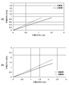
- FIG. 18A is a stress strain diagram obtained by a tensile strength test using the strength test samples 201 according to Comparative Examples 1 and 2.
- FIG. 18B is a stress strain diagram obtained by the tensile strength test using the strength test sample 101 according to Examples 1 and 2.
- FIG. 18A is a stress strain diagram obtained by a tensile strength test using the strength test samples 201 according to Comparative Examples 1 and 2.
- FIG. 18B is a stress strain diagram obtained by the tensile strength test using the strength test sample 101 according to Examples 1 and 2.
- FIG. 18A is a stress strain diagram obtained by a tensile strength test using the strength test samples 201 according to Comparative Examples 1 and 2.
- FIG. 18B is a stress strain diagram obtained by the tensile strength test using the strength test sample 101 according to Examples 1 and 2.
- the fixing structure 20 having the inclined portion 21 is illustrated, and in the second embodiment, the holding structure 120 having the inclined portion 121 is illustrated.
- the holding structure 120 is not limited to these configurations.
- As the fixing structure 20 and the holding structure 120 an arbitrary configuration made of FRP and having the inclined portions 21 and 121 can be adopted.
- the holding portions 22 and 122 which are cylindrical surfaces parallel to the Z-axis direction are provided.
- the parts 22 and 122 are not limited to this configuration.
- any configuration having a larger diameter than the inclined portions 21 and 121 can be employed.
- the rear end portion G having a large diameter of the inclined portions 21 and 121 may be configured as the holding portions 22 and 122.
Landscapes
- Engineering & Computer Science (AREA)
- Architecture (AREA)
- Civil Engineering (AREA)
- Structural Engineering (AREA)
- Physics & Mathematics (AREA)
- Health & Medical Sciences (AREA)
- Life Sciences & Earth Sciences (AREA)
- Chemical & Material Sciences (AREA)
- Analytical Chemistry (AREA)
- Biochemistry (AREA)
- General Health & Medical Sciences (AREA)
- General Physics & Mathematics (AREA)
- Immunology (AREA)
- Pathology (AREA)
- Bridges Or Land Bridges (AREA)
- Reinforcement Elements For Buildings (AREA)
- Investigating Strength Of Materials By Application Of Mechanical Stress (AREA)
- Ropes Or Cables (AREA)
Abstract
La présente invention concerne une structure de fixation pour un câble en matière plastique renforcée par des fibres qui est composée d'une matière plastique renforcée par des fibres et est disposée sur une partie d'extrémité longitudinale du câble en matière plastique renforcée par des fibres, ladite structure de fixation comprenant une unité de retenue et une partie inclinée ayant un diamètre qui devient plus petit à partir de l'unité de retenue vers la partie centrale longitudinale du câble en matière plastique renforcée par des fibres. La partie d'extrémité du câble en matière plastique renforcée par des fibres peut être retenue de manière excellente par cette structure de fixation.
Applications Claiming Priority (2)
| Application Number | Priority Date | Filing Date | Title |
|---|---|---|---|
| JP2015137298A JP6586695B2 (ja) | 2015-07-08 | 2015-07-08 | 繊維強化プラスチックケーブルの定着構造体及びその製造方法、強度試験方法、並びに強度試験用サンプル |
| JP2015-137298 | 2015-07-08 |
Publications (1)
| Publication Number | Publication Date |
|---|---|
| WO2017006647A1 true WO2017006647A1 (fr) | 2017-01-12 |
Family
ID=57685084
Family Applications (1)
| Application Number | Title | Priority Date | Filing Date |
|---|---|---|---|
| PCT/JP2016/065928 Ceased WO2017006647A1 (fr) | 2015-07-08 | 2016-05-30 | Structure de fixation pour un câble en matière plastique renforcée par des fibres, son procédé de fabrication, procédé d'essai de résistance et échantillon pour un essai de résistance |
Country Status (2)
| Country | Link |
|---|---|
| JP (1) | JP6586695B2 (fr) |
| WO (1) | WO2017006647A1 (fr) |
Families Citing this family (1)
| Publication number | Priority date | Publication date | Assignee | Title |
|---|---|---|---|---|
| JP7686187B2 (ja) * | 2020-09-11 | 2025-06-02 | 国立研究開発法人物質・材料研究機構 | 定着構造体 |
Citations (4)
| Publication number | Priority date | Publication date | Assignee | Title |
|---|---|---|---|---|
| JPH01114728U (fr) * | 1988-01-28 | 1989-08-02 | ||
| JPH06287949A (ja) * | 1993-04-02 | 1994-10-11 | Tokyu Constr Co Ltd | Frpケーブルの定着装置 |
| JP5514966B1 (ja) * | 2013-05-20 | 2014-06-04 | 極東鋼弦コンクリート振興株式会社 | 繊維強化プラスチック製線条体の定着具 |
| JP2014125707A (ja) * | 2012-12-27 | 2014-07-07 | Tokyo Seiko Co Ltd | 繊維強化プラスチック製線条体の端末定着構造および方法 |
-
2015
- 2015-07-08 JP JP2015137298A patent/JP6586695B2/ja active Active
-
2016
- 2016-05-30 WO PCT/JP2016/065928 patent/WO2017006647A1/fr not_active Ceased
Patent Citations (4)
| Publication number | Priority date | Publication date | Assignee | Title |
|---|---|---|---|---|
| JPH01114728U (fr) * | 1988-01-28 | 1989-08-02 | ||
| JPH06287949A (ja) * | 1993-04-02 | 1994-10-11 | Tokyu Constr Co Ltd | Frpケーブルの定着装置 |
| JP2014125707A (ja) * | 2012-12-27 | 2014-07-07 | Tokyo Seiko Co Ltd | 繊維強化プラスチック製線条体の端末定着構造および方法 |
| JP5514966B1 (ja) * | 2013-05-20 | 2014-06-04 | 極東鋼弦コンクリート振興株式会社 | 繊維強化プラスチック製線条体の定着具 |
Also Published As
| Publication number | Publication date |
|---|---|
| JP6586695B2 (ja) | 2019-10-09 |
| JP2017020217A (ja) | 2017-01-26 |
Similar Documents
| Publication | Publication Date | Title |
|---|---|---|
| CN1113139C (zh) | 一种电杆 | |
| CN203403607U (zh) | 一种能够连接单根frp绞线的连接器 | |
| WO2014196432A1 (fr) | Matériau composite de fibres à haute résistance, et corps structurel à brins ainsi que corps structurel multibrins | |
| JP5913085B2 (ja) | 繊維強化プラスチック製線条体の端末定着構造および方法 | |
| WO2022007705A1 (fr) | Matériau de fil composite renforcé par des fibres liées à un élastomère et son procédé de préparation | |
| CN103760016B (zh) | 一种用于测试复合材料界面力学性能的夹具及实验方法 | |
| Capela et al. | Fatigue strength of tubular carbon fibre composites under bending/torsion loading | |
| JP6586695B2 (ja) | 繊維強化プラスチックケーブルの定着構造体及びその製造方法、強度試験方法、並びに強度試験用サンプル | |
| CN108760469A (zh) | 一种陶瓷基复合材料榫连接结构高温强度测试试验装置及试验方法 | |
| CN107190988B (zh) | 一种预应力钢绞线牵引头 | |
| Bily et al. | Study of composite interface fracture and crack growth monitoring using carbon nanotubes | |
| JP7686187B2 (ja) | 定着構造体 | |
| Sabău et al. | Numerical simulation of flexural behavior of glass fiber reinforced polymer composites | |
| CN103342164B (zh) | 一种便于安装和预紧的复合材料柔性可承载的变形蒙皮 | |
| CN204531181U (zh) | 复合线状体的末端固定结构 | |
| CN111664152B (zh) | 一种杆件连接端头及其连接方法 | |
| CN104405136B (zh) | 非张拉式纤维预应力施加的方法 | |
| CN201793989U (zh) | 碳纤维复合芯倍容导线牵引绳 | |
| US20160229109A1 (en) | Composite rod with contiguous end terminations and methods for making them | |
| CN204418504U (zh) | 一种用于弦支结构的cfrp拉索 | |
| Yeung et al. | Composite tension members for structural applications | |
| Pan et al. | Experimental Investigation of Pin-Loaded CFRP-Strap Hangers for Through and Half-Through Arch Bridge | |
| JP2020144201A (ja) | 成形体 | |
| Tenorio et al. | Interfacial debonding of glass single fiber composites using the Johnson-Cook failure model | |
| JP5966390B2 (ja) | 連続繊維補強材及び連続繊維補強材の製造方法 |
Legal Events
| Date | Code | Title | Description |
|---|---|---|---|
| 121 | Ep: the epo has been informed by wipo that ep was designated in this application |
Ref document number: 16821118 Country of ref document: EP Kind code of ref document: A1 |
|
| NENP | Non-entry into the national phase |
Ref country code: DE |
|
| 122 | Ep: pct application non-entry in european phase |
Ref document number: 16821118 Country of ref document: EP Kind code of ref document: A1 |