WO2017006662A1 - Couvercle à charnière - Google Patents
Couvercle à charnière Download PDFInfo
- Publication number
- WO2017006662A1 WO2017006662A1 PCT/JP2016/066339 JP2016066339W WO2017006662A1 WO 2017006662 A1 WO2017006662 A1 WO 2017006662A1 JP 2016066339 W JP2016066339 W JP 2016066339W WO 2017006662 A1 WO2017006662 A1 WO 2017006662A1
- Authority
- WO
- WIPO (PCT)
- Prior art keywords
- hinge
- cover
- cover member
- connection
- door
- Prior art date
- Legal status (The legal status is an assumption and is not a legal conclusion. Google has not performed a legal analysis and makes no representation as to the accuracy of the status listed.)
- Ceased
Links
Images








Classifications
-
- E—FIXED CONSTRUCTIONS
- E05—LOCKS; KEYS; WINDOW OR DOOR FITTINGS; SAFES
- E05D—HINGES OR SUSPENSION DEVICES FOR DOORS, WINDOWS OR WINGS
- E05D7/00—Hinges or pivots of special construction
- E05D7/08—Hinges or pivots of special construction for use in suspensions comprising two spigots placed at opposite edges of the wing, especially at the top and the bottom, e.g. trunnions
- E05D7/082—Hinges or pivots of special construction for use in suspensions comprising two spigots placed at opposite edges of the wing, especially at the top and the bottom, e.g. trunnions the pivot axis of the wing being situated at a considerable distance from the edges of the wing, e.g. for balanced wings
- E05D7/086—Braking devices structurally combined with hinges
-
- E—FIXED CONSTRUCTIONS
- E05—LOCKS; KEYS; WINDOW OR DOOR FITTINGS; SAFES
- E05D—HINGES OR SUSPENSION DEVICES FOR DOORS, WINDOWS OR WINGS
- E05D11/00—Additional features or accessories of hinges
Definitions
- the present invention relates to a hinge cover that covers a hinge.
- the door is rotatably connected to the housing via a hinge.
- the hinge includes a housing-side hinge member attached to the housing and a door-side hinge member attached to the door. These hinge members are connected by connecting means such as a link mechanism.
- Patent Document 1 discloses a hinge cover that covers a hinge.
- the hinge cover includes a housing-side cover member fixed to the housing-side hinge member and a door-side cover member that is rotatably attached to the door-side hinge member.
- a groove is formed in the housing side cover member.
- a convex shaft portion is formed on the door-side cover member. The convex shaft portion is fitted in the groove so as to be slidable and rotatable.
- the hinge cover of the above-mentioned Patent Document 1 has only a role of improving the appearance by covering the hinge.
- An object of this invention is to raise added value by providing a damper function to a hinge cover.
- the present invention is a hinge cover that covers a hinge that rotatably connects a second member to a first member, A first cover portion having a first connection receiving portion and covering the first hinge portion on the first member side of the hinge; A second cover portion covering the second hinge portion on the second member side of the hinge; With The second cover part is positioned relative to the second hinge part, and the first and second connection receiving parts extend from the second connection receiving part to the first cover part. And a connecting cover member connected to be relatively displaceable, A damper for braking the relative displacement is provided between the connection cover member and the first cover portion and / or between the connection cover member and the second connection receiving portion. .
- One of the first connection receiving part and the connection cover member is provided with a rack, On the other of the first connection receiving portion and the connection cover member, a pinion is rotatably provided via the damper, When the angle of the second member with respect to the first member is within a braking angle range, the pinion meshes with the rack; It is preferable that the damper brakes the rotation of the pinion. Accordingly, the braking force of the damper can be exhibited within a range where the rack and the pinion are engaged with each other.
- the relative rotation includes relative rotation and relative slide.
- One of the first connection receiving part and the connection cover member is provided with a guide groove extending along the rack, It is preferable that a convex shaft portion is provided on the axis of the pinion, and the convex shaft portion is fitted into the guide groove so as to be slidable and rotatable.
- connection cover member is separable from the first or second connection receiving portion. Accordingly, when an obstacle is inserted between the connection cover member and the hinge, the connection cover member is separated from the first or second connection receiving portion, so that the obstacle is connected to the connection cover member and the hinge. It can prevent being pinched between them.
- One of the first connection receiving part and the connection cover member is provided with a guide groove
- the other of the first connection receiving portion and the connection cover member is provided with a convex shaft portion that is slidably and rotatably fitted in the guide groove
- the convex shaft portion can be pulled out from the guide groove to one side in the groove width direction of the guide groove.
- the convex shaft portion is accommodated in the guide groove, thereby stabilizing the connection state between the first connection receiving portion and the connection cover member. Can be retained.
- the convex shaft portion is one in the groove width direction from the guide groove.
- a groove side surface on one side of the groove width direction in a portion where the convex shaft portion is located in the separable angle range is inclined with respect to the bottom surface of the groove so as to overcome the convex shaft portion. It is preferable to allow.
- the connection state of the first connection receiving portion and the connection cover member is usually achieved by the convex shaft portion being accommodated in the guide groove. Can be held stably.
- the connection cover member can be separated from the first connection receiving portion by overcoming the inclined groove side surface of the convex shaft portion. Can be prevented from being sandwiched between the connecting cover member and the hinge.
- this invention is a hinge cover which covers the hinge which connects a 2nd member rotatably with respect to a 1st member, A first cover portion having a first connection receiving portion and covering the first hinge portion on the first member side of the hinge; A second cover portion covering the second hinge portion on the second member side of the hinge; With The second cover part includes a second connection receiving part fixed to the second hinge part, and a connection cover member straddling the first cover part from the second connection receiving part;
- the connecting cover member includes two connecting members connected to each other so as to be relatively displaceable, one connecting member is connected to the second connecting receiving portion so as to be relatively displaceable, and the other connecting member is the first connecting member.
- connection receiving part It is connected to the connection receiving part so that it can be displaced relatively,
- a damper for braking the vehicle is provided.
- the damper function can be imparted to the hinge by attaching the hinge cover to the hinge.
- FIG. 1 is a perspective view showing a hinge device including a hinge cover according to a first embodiment of the present invention mounted on a housing and a door of a door device and with the door opened.
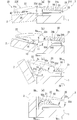
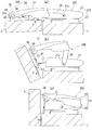
- Fig.2 (a) is a top view of the said hinge apparatus which made the door the open state.
- FIG.2 (b) is a top view of the said hinge apparatus which made the door the half-open state.
- FIG.2 (c) is a top view of the said hinge apparatus which made the door the semi-closed state.
- FIG. 2D is a plan view of the hinge device with the door closed.
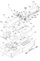
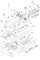
- FIG. 3 is an exploded perspective view of the hinge device.
- FIG. 1 is a perspective view showing a hinge device including a hinge cover according to a first embodiment of the present invention mounted on a housing and a door of a door device and with the door opened.
- Fig.2 (a) is a top view of the said hinge apparatus which made the door the open state.
- FIG.2 (b) is
- FIG. 4 is a rear view of the hinge device in the semi-closed state as viewed from the back side of the door device along the line IV-IV in FIG.
- FIG. 5A is a cross-sectional view of the hinge device in a half-open state along the line Va-Va in FIG.
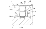
- FIG. 5B is a cross-sectional view of the hinge device in the closed state along the line Vb-Vb in FIG.
- FIG. 5C is a cross-sectional view of the hinge device in the closed state along the line Vc-Vc in FIG.
- Fig.6 (a) is sectional drawing which looked at the said hinge apparatus of the open state from the same cut surface as the same figure (b).
- FIG. 5A is a cross-sectional view of the hinge device in a half-open state along the line Va-Va in FIG.
- FIG. 5B is a cross-sectional view of the hinge device in the closed state along the line Vb-Vb in FIG.
- FIG. 5C is a cross
- FIG. 6B is a cross-sectional view of the hinge device in a semi-closed state along the line VIb-VIb in FIG.
- FIG.6 (c) is sectional drawing which looked at the said hinge apparatus of the closed state from the same cut surface as the same figure (b).
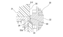
- Fig.7 (a) is sectional drawing to which the circular part VIIa of Fig.5 (a) was expanded.
- FIG.7 (b) is sectional drawing to which the circular part VIIb of FIG.5 (b) was expanded.
- FIG.7 (c) is sectional drawing to which the circular part VIIc of FIG.5 (c) was expanded.
- FIG. 8A is a cross-sectional view of the hinge device taken along the line VIIIa-VIIIa of FIG.
- FIG. 8B is a plan view of the hinge device in which the connection cover member is disconnected.
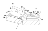
- Fig.9 (a) is the expanded sectional view which looked at the state in the middle of connection release of a connection cover member when it exists in a separable angle range from the same cut surface as FIG.7 (b).
- FIG. 9B is an enlarged cross-sectional view of the state in which the connection cover member is released from the same cut surface as that in FIG. 7B.
- FIG. 10 is an exploded perspective view of a hinge device including a hinge cover according to the second embodiment of the present invention.
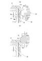
- FIG. 11 is an enlarged cross-sectional view of the hinge device of the second embodiment when viewed from a cut surface corresponding to FIG. 7A when in the half-open state, that is, in the separable angle range.
- FIG. 12A is a cross-sectional plan view of the hinge device of the second embodiment when viewed from the cut surface corresponding to FIG. 8A when in the half-open state, that is, in the separable angle range.
- FIG. 12B is a plan view of the hinge device in which the connection cover member of the second embodiment is released.
- FIG. 13 is an exploded perspective view of a hinge device including a hinge cover according to the third embodiment of the present invention.
- FIG. 14 is a cross-sectional view showing a peripheral portion of the second connection receiving portion of the third embodiment in a cross section orthogonal to the rotation axis.
- FIG. 15 is a plan view of the hinge device in which the connection cover member of the third embodiment is released.
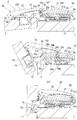
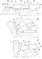
- FIG. 16 shows a hinge device including a hinge cover according to a fourth embodiment of the present invention, wherein FIG. 16 (a) is a plan view in the open state, and FIG. It is a top view at the time of a half open state, The figure (c) is a top view at the time of a closed state.
- FIG. 17 shows a hinge device including a hinge cover according to a fifth embodiment of the present invention.
- FIG. 17 (a) is a plan view in the open state, and FIG.
- FIG. 18 shows a hinge device including a hinge cover according to a sixth embodiment of the present invention.
- FIG. 18 (a) is a plan view in the open state
- FIG. 18 (b) It is a top view at the time of a half open state
- the figure (c) is a top view at the time of a closed state.
- FIG.1 and FIG.2 show a first embodiment of the present invention.
- the door apparatus M is provided with the housing
- the door 2 is connected to the housing 1 via a hinge device 3 so as to be rotatable about an axis that is vertical (a direction orthogonal to the paper surface in FIG. 2). Thereby, the door 2 is opened and closed.
- the door device M is applied to, for example, a cupboard or other storage device with a hinged door.
- the hinge device 3 includes a hinge 10 and a hinge cover 20.
- the hinge 10 includes a first hinge portion 11 on the housing 1 side, a second hinge portion 12 on the door 2 side, and a coupling mechanism 15.
- the first hinge part 11 has a long box shape extending in the depth direction (left and right in FIG. 2).
- a plate-like first mounting plate 13 extends from the first hinge portion 11 to both the upper and lower sides (in the direction orthogonal to the paper surface in FIG. 2).
- the first mounting plate 13 is screwed to the housing 1. As a result, the 1st hinge part 11 is attached to the housing
- the second hinge portion 12 has a square plate-like second mounting plate 14.
- the second hinge plate 12 is attached to the door 2 by screwing the second attachment plate 14 to the door 2.
- a cup portion 12 c is provided at the center of the second mounting plate 14.
- the first hinge portion 11 and the second hinge portion 12 are rotatably connected via a connecting mechanism 15.
- the connection mechanism 15 is configured by a four-node link mechanism, but is not limited thereto, and may be another link mechanism such as a seven-node link mechanism or a single-axis hinge mechanism.
- a catch mechanism 16 is incorporated in the coupling mechanism 15.
- the catch mechanism 16 includes a torsion spring 16a.
- the torsion spring 16a urges the second hinge portion 12 to rotate in the opening direction (counterclockwise in FIG. 6A) with respect to the first hinge portion 11,
- the second hinge portion 12 is urged to rotate with respect to the first hinge portion 11 in the closing direction (clockwise direction in FIG. 6C).
- the catch mechanism 16 may operate only when the door 2 is close to the closed state, and may not operate when the door 2 is close to the open state.
- a hinge cover 20 is attached to the hinge 10.
- the hinge cover 20 covers the front side (the upper side in FIG. 1) of the hinge 10. Throughout the entire state of the door 2 from fully closed to fully open, almost the entire hinge 10 is covered with the hinge cover 20.
- the hinge cover 20 includes a first cover part 21 ⁇ / b> X attached to the first hinge part 11 and a second cover part 22 ⁇ / b> X attached to the second hinge part 12.
- the first cover portion 21 ⁇ / b> X includes a first cover member 21 and a first attachment cover member 23.
- the first cover member 21 includes a front plate portion 21a and a pair of side plate portions 21b and 21b facing each other in the width direction, and has a long case shape with a U-shaped cross section.
- the first cover member 21 covers the first hinge part 11 as a whole by covering the first hinge part 11 with the longitudinal direction in the depth direction and the width direction in the vertical direction (vertical). .
- the first cover member 21 can be attached to and detached from the first hinge portion 11, and is fixed to the first hinge portion 11 in a state where the first cover member 21 is attached to the first hinge portion 11.
- the first mounting cover member 23 has a flat case shape.
- a cutout recess 23 c is formed at the center of the first mounting cover member 23.
- the first mounting cover member 23 covers the first mounting plate 13 as a whole by covering the first mounting plate 13 from the front side (upper side in FIG. 3).
- the 1st hinge part 11 is inserted by the notch recessed part 23c.
- the first cover member 21 and the first attachment cover member 23 are detachably fitted.
- the second cover portion 22X includes a connection cover member 22 (second cover member) and a second attachment cover member 24.
- the second mounting cover member 24 has a flat case shape.
- the second mounting cover member 24 is screwed to the door 2 together with the second mounting plate 14 and fixed.
- the second mounting cover member 24 covers the second mounting plate 14 by covering the second mounting plate 14 from the front side (upper side in FIG. 3).
- a notch recess 24 c is formed at the center of the second mounting cover member 24.
- the cup part 12c is located in the notch recess 24c.
- the connecting cover member 22 has a front plate portion 22a and a pair of side plate portions 22b and 22b facing each other in the width direction, and has a long case shape with a U-shaped cross section. Yes.
- the connection cover member 22 is bridged from the second attachment cover member 24 to the first cover member 21 with the width direction directed in the vertical direction.
- connection cover member 22 is connected to the second mounting cover member 24 so as to be capable of relative displacement, and is connected to the first cover member 21 so as to be capable of relative displacement.
- a rotation shaft 42 is provided at the door side end 22 e (second end) of the connection cover member 22.
- the second mounting cover member 24 is provided with a shaft support portion 44 (second connection receiving portion).
- the shaft support portion 44 is fixed in position with respect to the second hinge portion 12.
- the shaft support portion 44 has an annular shape or a cylindrical shape.
- the axes of the rotating shaft 42 and the shaft support 44 are directed in the width direction of the connection cover member 22, that is, vertically (up and down).
- the rotating shaft 42 is rotatably inserted through the shaft support portion 44.
- the connection cover member 22 is connected to the shaft support portion 44 and the second mounting cover member 24 so as to be rotatable around the rotation shaft 42.
- the housing side end 22c (first end) of the connection cover member 22 is provided with a convex shaft portion 34.
- a guide groove 54 is provided in the first cover member 21.
- the convex shaft portion 34 is fitted in the guide groove 54 so as to be slidable and rotatable.
- connection cover member 22 covers the cup portion 12 c and the connection mechanism 15 (between the hinge portions 11 and 12) of the hinge 10.
- the housing side end 22c of the connection cover member 22 is moved to the first cover member 21. Is located at the front end (left end in FIG. 2A).
- the connection cover member 22 extends from the second mounting cover member 24 to the front end portion of the first cover member 21, and covers the cup portion 12c and the connection mechanism 15 from the front side (upper side in FIG. 1).
- connection cover member 22 covers from the front side (upper side in FIG. 2B and FIG. 2C) from the second attachment cover member 24 to the intermediate portion of the first cover member 21.
- the cup part 12c and the connection mechanism 15 are covered.
- a gap 3 s that is closed in a plan view is formed between the connection cover member 22 and the second hinge portion 12.
- connection cover member 22 covers from the front side (FIG. 2D) over almost the entire length of the first cover member 21 from the second attachment cover member 24.
- a first connection receiving portion 50 is formed on the outer surface of each side plate portion 21 b of the first cover member 21.
- the 1st connection receiving part 50 is comprised by the surface dented rather than the part 21d which is not the 1st connection receiving part 50 in the outer surface of the side-plate part 21b.
- the first connection receiving portion 50 reaches the corner portion between the plate portions 21a and 21b from the intermediate portion in the short direction (up and down in FIG. 3) of the side plate portion 21b, and the longitudinal direction of the first cover member 21 (FIG. 5 ( c) in a direction perpendicular to the paper surface.
- the 1st connection receiving part 50 bends in the L shape near the edge part of the front side (door 2 side), and comprises the bending part 50c.
- the position of the first connection receiving portion 50 is fixed with respect to the first hinge portion 11.
- the boundary between the first connection receiving portion 50 and the portion 21d that is not the first connection receiving portion 50 on the outer surface of the side plate portion 21b is a step 50d.
- the step 50d extends along the first connection receiving portion 50 and is bent in an L shape near the front (door 2 side) end.
- a rack 53 is formed in a part of the step 50d. That is, the first connection receiving portion 50 is provided with a rack 53.
- the rack 53 is provided from the vicinity of the center of the first cover member 21 in the longitudinal direction to the end on the back side (right side in FIGS. 3 and 6).
- the rack 53 is not formed at the step 50d from the vicinity of the central portion in the longitudinal direction of the first cover member 21 to the front end.
- the guide groove 54 is formed in the first connection receiving portion 50.
- the guide groove 54 is narrower than the first connection receiving portion 50, extends over substantially the entire area of the first connection receiving portion 50, and is bent in an L shape at the bent portion 50c.
- the guide groove 54 on the back side (the right side in FIG. 6B) from the bent portion 50 c extends along the extending direction of the rack 53.
- the groove side surfaces 54c and 54d on both sides in the groove width direction (up and down in FIG. 7C) of the guide groove 54 on the back side from the bent portion 50c are both relative to the groove bottom surface 54b. They are almost orthogonal.
- the guide groove portion 55 (the portion corresponding to the separable angle range described later) on the front side (left side in the figure) of the bent portion 50c in the guide groove 54 is opposite to the front plate portion 21a. (Lower side in the figure) and it extends diagonally toward the front (left side in the figure).
- the guide groove portion 55 is adjacent to and parallel to the front oblique edge portion 21e of the side plate portion 21b.
- the front oblique edge portion 21e extends obliquely forward from the front plate portion 21a. Further, as shown in FIG. 7B, the cross section of the front oblique edge portion 21e approaches the guide groove portion 55 toward the outer side in the width direction of the connection cover member 22 (left and right in FIG. 7B). It is diagonal.
- the groove side surface 55c on the front oblique edge portion 21e side (one side in the groove width direction) of the guide groove portion 55 is inclined with respect to the groove bottom surface 54b. That is, the groove side surface 55c is a slope that approaches the front oblique edge portion 21e as it goes outward in the width direction of the connection cover member 22 (left and right in FIG. 7B). Further, as shown in FIG. 6B, the groove side surface 55c extends over the entire extending direction of the guide groove portion 55 and beyond the bent portion 50c to the back side (right side in FIG. 6B). ) Of the groove side surface 54c.
- the groove side surface 55d on the step 50d side (opposite to the groove width direction) in the guide groove portion 55 is substantially orthogonal to the groove bottom surface 54b.
- the groove side surface 55d is connected to the groove side surface 54d on the back side (right side in FIG. 6B) at an angle from the bent portion 50c.
- a pair of dampers 30 and 30 are disposed on both sides in the width direction of the housing side end 22c of the connection cover member 22.
- a damper holding portion 22 d is provided at the housing side end portion of each side plate portion 22 b of the connection cover member 22.
- the damper holding portion 22d has a circular case shape that opens to the inside in the width direction of the connection cover member 22.
- the damper 30 is held by each damper holding portion 22d.
- the damper 30 is interposed between the cover members 21 and 22 and brakes the relative displacement of the connection cover member 22 with respect to the first cover member 21.
- the damper 30 is composed of a rotary damper including a damper main body 31 and a rotor 32.
- the damper main body 31 has a circular case shape.
- the damper main body 31 is provided with a pair of locking hooks 31f and 31f.
- the damper main body 31 is accommodated in the damper holding portion 22d, and the locking hook 31f is locked in the locking hole portion 22f of the damper holding portion 22d. Thereby, the damper main body 31 is detachably fixed to the connection cover member 22.
- the rotor 32 is circular.
- the rotor 32 is fitted in the damper main body 31 so as to be rotatable about its own axis with the axis line directed in the width direction of the connecting cover member 22 (left and right in FIG. 5C).
- a pinion 33 protrudes from the surface of the rotor 32 facing the inner side in the width direction of the connecting cover member 22.
- the connection cover member 22 is provided with the pinion 33 via the damper 30.
- the convex shaft portion 34 is formed to protrude from the surface of the pinion 33 facing the inner side in the width direction of the connecting cover member 22. As shown in FIG.7 (c), the outer periphery of the front-end
- the pinion 33 and the convex shaft portion 34 are disposed on the same axis as the rotor 32 and are integrated with the rotor 32 so as to be rotatable about its own axis with respect to the connection cover member 22.
- a viscous fluid is sealed between the damper main body 31 and the rotor 32 and is sealed by an annular seal member 35 (FIG. 3).
- a braking torque is generated when the rotor 32 rotates.
- the damper 30 generates a braking torque regardless of the rotation direction of the rotor 32, but the braking torque is generated only when the rotor 32 rotates in the closing direction of the door 2, and the rotor 32 rotates in the opening direction of the door 2. When doing so, braking torque may not be generated.
- the pinion 33 fits in the first connection receiving portion 50, and the convex shaft portion 34 fits in the guide groove 54. As shown in FIG.
- the pinion 33 and the convex shaft portion 34 are slidable in the extending direction of the guide groove 54 and rotatable about its own axis. As a result, the housing side end 22 c of the connection cover member 22 is slidable over the entire area of the first connection receiving portion 50.
- connection cover member 22 when the pinion 33 is located on the front side from the vicinity of the bent portion 50 c of the first connection receiving portion 50 and the convex shaft portion 34 is located in the guide groove portion 55, the connection cover member 22.
- the convex shaft portion 34 can be pulled out from the guide groove 55 toward the front oblique edge portion 21e (one side in the groove width direction) by an external force of a certain level or more.
- the groove side surface 55c forming the slope of the guide groove portion 55 allows the convex shaft portion 34 to get over.
- the hinge 10 can be covered with the hinge cover 20 through the entire state of the door 2 from the fully closed state to the fully open state, and the appearance can be improved.
- FIG. 6 (a) when the door 2 is closed from the open state, the pinion 33 is in front of the rack 53 (in FIG. 6) until the door 2 is in the half-closed state (FIG. 6 (b)).
- the pinion 33 and the rack 53 are not engaged with each other. Therefore, the braking force of the damper 30 does not work and the door 2 can be moved smoothly.
- the pair of groove side surfaces 54c and 54d of the guide groove 54 guides the convex shaft portion 34 from both sides, so that the pinion 33 is perpendicular to the step 50d (in FIG. 7C).
- the pinion 33 and the rack 53 can be firmly engaged with each other. Since the door 2 is urged to rotate in the closing direction by the catch mechanism 16, the door 2 is automatically and reliably secured even if the door 2 is not forced to close against the braking force of the damper 30. Can be fully closed.
- the damper 30 Since the damper 30 is provided between the cover members 21 and 22, the range in which the braking force of the damper 30 works and the range in which the damper 30 does not work can be determined only by the relative positions of the cover members 21 and 22. Therefore, it is possible to prevent the range in which the braking force is applied from changing depending on the attachment position of the hinge device 3 to the housing 1 and the door 2. According to the hinge device 3, a damper function can be incorporated into the existing hinge 10 by retrofitting. Thereby, the added value of the hinge cover 20 can be increased.
- the convex shaft portion 34 when the door 2 is in an open state to a half-open state (separable angle range), the convex shaft portion 34 is positioned in the guide groove 55. At this time, normally, the convex shaft portion 34 can be smoothly slid along the guide groove 55. The convex shaft portion 34 is locked from both sides by the groove side surfaces 55 c and 55 d of the guide groove 55. Unless a torque of a certain magnitude or greater, which will be described later, is applied, the convex shaft portion 34 does not get over the inclined groove side surface 55c, and the connecting cover member 22 is not separated from the first cover member 21.
- the convex shaft portion 34 gets over the groove side surface 55c, so that it protrudes from the guide groove portion 55 to the front side (one side in the groove width direction, the upper side in the figure).
- the connection cover member 22 rotates about the rotation shaft 42 and is separated from the first cover member 21. As a result, it is possible to avoid the obstacle 9 from being strongly sandwiched between the connecting cover member 22 and the hinge 10.
- FIGS. 10 to 12 show a second embodiment of the present invention.
- the second embodiment relates to a modification of the separation structure of the first cover member 21 and the connection cover member 22.
- a flattening portion 56 is formed in a portion (a portion corresponding to the separable angle range) on the front side of the bent portion 50 c in the guide groove 54 of the first cover member 21 of the hinge cover 20 ⁇ / b> B. ing.
- the flattening portion 56 is a flat surface that is flush with the groove bottom surface 54b, extends from the groove side surface 55d to the front side (upper side in FIG. 11), and reaches the front oblique edge portion 21f of the side plate portion 21b.
- a torsion spring 26 (biasing means) is provided between the connecting cover member 22 and the second mounting cover member 24. As shown in FIG. The torsion spring 26 is attached to the shaft support portion 44, and one end portion 26 a of the torsion spring 26 is locked to the locking portion 44 h of the shaft support portion 44. The other end 26 b of the torsion spring 26 is locked in the locking hole 22 h of the connection cover member 22. The torsion spring 26 urges the casing-side end 22c of the connection cover member 22 to rotate in the direction in which it is pressed against the first cover member 21 (clockwise in FIG. 12A).
- the convex shaft portion 34 is slid along the groove side surfaces 54d and 55d. Even when the door 2 is in an open state to a half-open state (separable angle range) and the convex shaft portion 34 is in the flattening portion 56, the convex shaft portion 34 is removed from the flattening portion 56 by the urging force of the torsion spring 26. It is possible to prevent it from slipping out (upward in FIG. 12A).
- connection cover member 22 is moved toward the first cover member 21 by the urging force of the torsion spring 26 in FIG. Rotated around.
- the convex shaft portion 34 passes through the flattening portion 56 and fits in the guide groove 54. Thereby, the connection cover member 22 can be connected to the first cover member 21 again.
- the first connection receiving portion 50 includes a separation allowing portion (an inclined groove side surface 55 c or a flattening portion 56 of the housing side end portion 22 c of the connection cover member 22. Etc.) is not formed.
- the groove side surfaces 54 e and 54 f on both sides of the guide groove 54 are substantially orthogonal to the groove bottom surface 54 b over the entire area of the guide groove 54. Instead, the door side end 22 e of the connection cover member 22 is separable from the second mounting cover member 24.
- a notch 44 c is formed at one place in the circumferential direction of the shaft support portion 44 (second connection receiving portion) (a portion corresponding to the separable angle range).
- the notch 44 c extends over the entire axial length of the shaft support 44.
- the notch 44 c is positioned on the front side (upward in FIG. 15) with respect to the center of the shaft support 44.
- connection cover member 22 when the obstacle 9 is sandwiched between the gaps 3s in the half-open to open state, when a force is applied to the connection cover member 22 in the front side direction (upward in FIG. 15), the connection cover member 22 is Rotating about 34, the rotating shaft 42 comes out through the notch 44c. As a result, the connection cover member 22 is separated from the second attachment cover member 24. As a result, the obstacle 9 can be prevented from being strongly pinched between the connection cover member 22 and the hinge 10. When the opening degree of the door 2 is closer to the closed side than the half-open state, the rotating shaft 42 does not come out of the notch 44c. Therefore, the connection cover member 22 is prohibited from being separated from the second mounting cover member 24.
- FIG. 16 shows a fourth embodiment of the present invention.
- the connection cover member 25 includes two connection members 27 and 28.
- One connecting member 27 has the same shape as the connecting cover member 22 of the first to third embodiments.
- the door-side end portion 27e of the connecting member 27 is connected to the shaft support portion 44 (second connection receiving portion) of the second mounting cover member 24 via the rotating shaft 42 so as to be rotatable (relatively displaceable).
- the casing-side end portion 27c of the connecting member 27 and one end portion of the other connecting member 28 are connected so as to be rotatable (relatively displaceable) about an axis parallel to the rotating shaft 42.
- the connecting member 28 extends to the first cover member 21.
- the side plate portion 21b of the first cover member 21 of the hinge cover 20D has a first connection receiving portion 21c instead of the groove-shaped first connection receiving portion 50 of the first to third embodiments (FIGS. 1 to 15). Is provided. Although detailed illustration is omitted, the first connection receiving portion 21c includes a bearing portion, a shaft member, and the like. The other end of the coupling member 28 and the first coupling receiving portion 21 c are coupled so as to be rotatable about an axis parallel to the rotation shaft 42.
- the hinge cover 20D cooperates with the hinge portions 11 and 12 to constitute a four-bar linkage mechanism.
- the damper holding part 27d is provided in the housing side end part 27c of the connecting member 27.
- the damper 30 is accommodated in the damper holding portion 27d. Since the damper 30 is interposed between the two connecting members 27 and 28, the relative rotation (relative displacement) between the connecting members 27 and 28 is braked. As a result, the opening / closing operation
- FIG. 17 shows a fifth embodiment of the present invention.
- the fifth embodiment relates to a modification of the fourth embodiment (FIG. 16), and the connection cover member 25 of the hinge cover 20 ⁇ / b> E includes two connection members 27 and 28 as in the fourth embodiment.
- the hinge cover 20E forms a four-bar linkage mechanism in cooperation with the hinge portions 11 and 12.
- the hinge cover 20E of the fifth embodiment is different from the hinge cover 20D of the fourth embodiment in the arrangement position of the damper 30.
- the damper 30 is provided between the door side end portion 27 e of the connecting member 27 and the shaft support portion 44 of the second mounting cover member 24.
- the damper 30 brakes the rotation (relative displacement) of the connecting member 27 with respect to the second mounting cover member 24.
- casing 1 of the door 2 can be braked.
- FIG. 18 shows a sixth embodiment of the present invention.
- the sixth embodiment relates to a further modification of the fourth embodiment (FIG. 16), and the connection cover member 25 of the hinge cover 20F is composed of two connection members 27 and 28 as in the fourth embodiment.
- the four-bar linkage mechanism is configured in cooperation with the hinge portions 11 and 12.
- the damper 30 is provided between the connection member 28 and the first connection receiving portion 21c of the first cover member 21.
- the rotation (relative displacement) of the connecting member 28 with respect to the first cover member 21 is braked by the damper 30.
- casing 1 of the door 2 can be braked.
- the rack 53 may be provided on the connection cover member 22, and the pinion 33 may be rotatably provided on the first cover member 21 via the damper 30.
- the guide cover 54 may be provided in the connection cover member 22, and the convex shaft portion 34 may be provided in the first cover member 21.
- the rotation shaft 42 may be provided on the second attachment cover member 24, and the shaft support portion 44 may be provided on the connection cover member 22.
- the rotating shaft 42 constitutes a “second connection receiving portion” in the claims.
- the 2nd attachment cover member 24 may be abbreviate
- the first cover member 21 and the first attachment cover member 23 may be integrated.
- the first connection receiving portion 50 may be provided on the first attachment cover member 23.
- the first attachment cover member 23 may be omitted.
- the first cover part 21 ⁇ / b> X may have only the first cover member 21.
- the hinge covers 20, 20B to 20F do not necessarily cover the whole or substantially the entire hinge 10, and may cover only a part of the hinge 10.
- the hinge covers 20, 20B to 20F may cover about 30 to 70% of the hinge 10 or about 50%.
- the ratio of the hinge covers 20, 20B to 20F covering the hinge 10 may be changed.
- the damper 30 may be provided between a portion of the first cover portion 21 ⁇ / b> X other than the first connection receiving portion 50 and the connection cover member 22.
- a rack 53 is formed in a portion different from the first connection receiving portion 50, and the rack 53 is screwed with the pinion 33 of the damper 30.
- the damper 30 may be provided between the connection cover member 22 and the second attachment cover member 24 as in the fifth embodiment (FIG. 17).
- the damper 30 may be incorporated between the rotating shaft 42 and the shaft support portion 44.
- the convex shaft portion 34 may be provided directly (without a damper) on the housing side end portion 22c of the connection cover member 22.
- the pinion 33 and the rack 53 may be omitted.
- the damper 30 may be provided both between the connection cover member 22 and the first connection receiving portion 50 and between the connection cover member 22 and the second connection reception portion 44.
- the damper 30 is provided between the two connecting members 27 and 28, and between the one connecting member 27 and the shaft support portion 44 (second connecting receiving portion). In addition, it may be provided in two places between the other connecting member 28 and the first connection receiving portion 21c, or may be provided in all of these three places.
- the damper 30 is not limited to a rotary damper and may be a linear damper.
- the linear damper may be rotatably connected to a portion of the first cover portion 21X other than the first connection receiving portion 50 and the connection cover member 22.
- connection mode and the relative displacement mode of the first and second cover parts 21X and 22X are not limited to those of the embodiment.
- the housing-side end 22c of the connection cover member 22 is connected to the first cover member 21 so as to be rotatable and non-slidable
- the door-side end 22e of the connection cover member 22 is
- the second mounting cover member 24 may be connected to be rotatable and slidable.
- the damper 30 may be provided between the connection cover member 22 and the first cover member 21, or may be provided between the connection cover member 22 and the second attachment cover member 24.
- the first cover member 21 may be relatively displaceable with respect to the first attachment cover member 23 and thus the first hinge portion 11.
- first cover member 21 may be rotatable with respect to the first attachment cover member 23 and thus the first hinge portion 11.
- the connection cover member 22 may be rotatable with respect to the second attachment cover member 24.
- the first cover member 21 and the connection cover member 22 may be slidably connected to each other.
- the relative slide between the first cover member 21 and the connecting cover member 22 may be braked by a linear damper.
- the first cover member 21 may cover the front side of the connection cover member 22.
- the damper 30 may operate when the door 2 is close to the open state.
- the range on the open side of the door 2 may be a braking angle range.
- the damper 30 may operate when the door 2 is close to the open state and close to the closed state.
- the range on the open side and the range on the closed side of the door 2 may be a braking angle range.
- the damper 30 may operate in the entire opening / closing range of the door 2.
- the entire opening / closing range of the door 2 may be a braking angle range.
- the rack 53 may be provided over the entire region of the step 50d.
- the pinion 33 and the rack 53 may always mesh with each other.
- connection cover member 22 When the door 2 is close to the closed state, the connection cover member 22 may be separable from the first cover member 21 or the second attachment cover member 24.
- the range on the closed side of the door 2 may be a separable angle range.
- the connection cover member 22 When the door 2 is in a half-open to half-closed state, the connection cover member 22 may be separable from the first cover member 21 or the second attachment cover member 24.
- the middle part of the opening / closing range of the door 2 may be a separable angle range.
- the connecting cover member 22 When the door 2 is close to the open state and close to the closed state, the connecting cover member 22 may be separable from the first cover member 21 or the second mounting cover member 24.
- the open side range and the closed side range of the door 2 may be a separable angle range.
- the connection cover member 22 may be separable from the first cover member 21 or the second attachment cover member 24 in the entire opening / closing range of the door 2.
- the two connecting members 27 and 28 may be separable. May be separable from the shaft support portion 44 (second connection receiving portion), and the other connection member 28 may be separable from the first connection receiving portion 21c.
- the door 2 may correspond to the “first member” in the claims, and the housing 1 may correspond to the “second member” in the claims.
- the door 2 may be provided with the first hinge part 11 and the first cover part 21X, and the housing 1 may be provided with the second hinge part 12 and the second cover part 22X.
- the field of application of the present invention is not limited to the door device M of a storage tool such as a cupboard.
- One of the first and second members may be a housing of the building, and the other of the first and second members may be an entrance door provided in the housing.
- the present invention can be applied to a hinge of a door of a storage tool such as a cupboard.
Landscapes
- Engineering & Computer Science (AREA)
- Mechanical Engineering (AREA)
- Structural Engineering (AREA)
- Hinge Accessories (AREA)
- Hinges (AREA)
Abstract
La présente invention concerne un couvercle à charnière monté sur une charnière, permettant de transmettre une fonction d'amortissement à la charnière. Une première partie de couvercle (21X) d'un couvercle à charnière (20) est fixée à une première partie de charnière (11) sur un côté de premier élément (1). Une seconde partie de couvercle (22X) est fixée à une seconde partie de charnière (12) sur un côté de second élément (2). Un élément de couvercle de liaison (22) de la seconde partie de couvercle (22X) est disposé de manière à s'étendre d'une seconde partie de réception de liaison (44) de la seconde partie de couvercle (22X) à la première partie de couvercle (21X). L'élément de couvercle de liaison (22) est relié à la seconde partie de réception de liaison (44) de manière à pouvoir effectuer un déplacement relatif, et il est relié à une première partie de réception de liaison (50) de la première partie de couvercle (21X) de manière à pouvoir effectuer un déplacement relatif. Un amortisseur (30) pour amortir le déplacement relatif est disposé entre l'élément de couvercle de liaison (22) et la première partie de couvercle (21X).
Priority Applications (1)
| Application Number | Priority Date | Filing Date | Title |
|---|---|---|---|
| JP2016559454A JP6339695B2 (ja) | 2015-07-06 | 2016-06-02 | ヒンジカバー |
Applications Claiming Priority (2)
| Application Number | Priority Date | Filing Date | Title |
|---|---|---|---|
| JP2015135333 | 2015-07-06 | ||
| JP2015-135333 | 2015-07-06 |
Publications (1)
| Publication Number | Publication Date |
|---|---|
| WO2017006662A1 true WO2017006662A1 (fr) | 2017-01-12 |
Family
ID=57685434
Family Applications (1)
| Application Number | Title | Priority Date | Filing Date |
|---|---|---|---|
| PCT/JP2016/066339 Ceased WO2017006662A1 (fr) | 2015-07-06 | 2016-06-02 | Couvercle à charnière |
Country Status (2)
| Country | Link |
|---|---|
| JP (1) | JP6339695B2 (fr) |
| WO (1) | WO2017006662A1 (fr) |
Cited By (3)
| Publication number | Priority date | Publication date | Assignee | Title |
|---|---|---|---|---|
| CN108222725A (zh) * | 2018-01-13 | 2018-06-29 | 广东炬森五金精密制造有限公司 | 暗铰链及应用其的家具 |
| EP3633128A4 (fr) * | 2017-05-24 | 2021-02-24 | Sugatsune Kogyo Co., Ltd. | Dispositif pour portes |
| GB2592270B (en) * | 2020-02-24 | 2022-09-07 | Titus D O O Dekani | Improvements in hinge assemblies |
Families Citing this family (1)
| Publication number | Priority date | Publication date | Assignee | Title |
|---|---|---|---|---|
| KR102558155B1 (ko) * | 2023-05-17 | 2023-07-21 | 삼성정밀공업 주식회사 | 도어경첩 보호덮개 |
Citations (2)
| Publication number | Priority date | Publication date | Assignee | Title |
|---|---|---|---|---|
| JPH02123571U (fr) * | 1989-03-20 | 1990-10-11 | ||
| JP4308254B2 (ja) * | 2004-03-31 | 2009-08-05 | スガツネ工業株式会社 | ダンパー付きヒンジ |
-
2016
- 2016-06-02 JP JP2016559454A patent/JP6339695B2/ja not_active Expired - Fee Related
- 2016-06-02 WO PCT/JP2016/066339 patent/WO2017006662A1/fr not_active Ceased
Patent Citations (2)
| Publication number | Priority date | Publication date | Assignee | Title |
|---|---|---|---|---|
| JPH02123571U (fr) * | 1989-03-20 | 1990-10-11 | ||
| JP4308254B2 (ja) * | 2004-03-31 | 2009-08-05 | スガツネ工業株式会社 | ダンパー付きヒンジ |
Cited By (5)
| Publication number | Priority date | Publication date | Assignee | Title |
|---|---|---|---|---|
| EP3633128A4 (fr) * | 2017-05-24 | 2021-02-24 | Sugatsune Kogyo Co., Ltd. | Dispositif pour portes |
| US11168502B2 (en) | 2017-05-24 | 2021-11-09 | Sugatsune Kogyo Co., Ltd. | Door device |
| CN108222725A (zh) * | 2018-01-13 | 2018-06-29 | 广东炬森五金精密制造有限公司 | 暗铰链及应用其的家具 |
| CN108222725B (zh) * | 2018-01-13 | 2024-01-30 | 广东炬森精密科技股份有限公司 | 暗铰链及应用其的家具 |
| GB2592270B (en) * | 2020-02-24 | 2022-09-07 | Titus D O O Dekani | Improvements in hinge assemblies |
Also Published As
| Publication number | Publication date |
|---|---|
| JPWO2017006662A1 (ja) | 2017-07-13 |
| JP6339695B2 (ja) | 2018-06-06 |
Similar Documents
| Publication | Publication Date | Title |
|---|---|---|
| JP6339695B2 (ja) | ヒンジカバー | |
| JP6291028B2 (ja) | ロック装置 | |
| AU2003241805A1 (en) | Take up-type screen device | |
| JP5146228B2 (ja) | 車両用ドアハンドル | |
| CN109972938B (zh) | 一种用于打开车门的机构 | |
| JP2020094330A (ja) | ローラユニット | |
| ITTO20030058U1 (it) | Dispositivo per la frenatura del movimento di uno sportello, cassetto, o simile organo mobile, provvisto di mezzi di bloccaggio rilasciabili . | |
| JP2007126109A (ja) | 車両用グローブボックスのヒンジ構造 | |
| KR102093987B1 (ko) | 손끼임방지 도어용 안전장치 | |
| KR200487213Y1 (ko) | 문 급속 닫힘 방지 기능을 갖는 완충기구 | |
| JP5470870B2 (ja) | 窓開閉装置 | |
| JP6602531B2 (ja) | 速度調整装置及びこれを備えた日射遮蔽装置 | |
| JP6647513B1 (ja) | 開度制限蝶番及びその部品 | |
| JP6898641B2 (ja) | スパイラルバランス装置 | |
| JP2016007864A (ja) | 両開き収納装置 | |
| JP5235465B2 (ja) | ロック装置 | |
| JP6603117B2 (ja) | ヒンジ装置及び基部 | |
| JP6879817B2 (ja) | 折戸装置 | |
| KR102271580B1 (ko) | 차량용 인사이드 도어 핸들 | |
| JP7456996B2 (ja) | 洗濯機 | |
| JP6325386B2 (ja) | 扉操作補助装置 | |
| KR102282213B1 (ko) | 손 끼임 방지장치를 갖춘 창호용 경첩 장치 | |
| JP5876665B2 (ja) | 折戸 | |
| KR102587083B1 (ko) | 차량용 도어 잠금장치 | |
| EP3665353B1 (fr) | Dispositif de commande d'ouverture/fermeture de battants de porte d'un élément d'ameublement et analogue |
Legal Events
| Date | Code | Title | Description |
|---|---|---|---|
| ENP | Entry into the national phase |
Ref document number: 2016559454 Country of ref document: JP Kind code of ref document: A |
|
| 121 | Ep: the epo has been informed by wipo that ep was designated in this application |
Ref document number: 16821133 Country of ref document: EP Kind code of ref document: A1 |
|
| NENP | Non-entry into the national phase |
Ref country code: DE |
|
| 122 | Ep: pct application non-entry in european phase |
Ref document number: 16821133 Country of ref document: EP Kind code of ref document: A1 |