WO2017006673A1 - 高周波誘電加熱装置 - Google Patents
高周波誘電加熱装置 Download PDFInfo
- Publication number
- WO2017006673A1 WO2017006673A1 PCT/JP2016/066624 JP2016066624W WO2017006673A1 WO 2017006673 A1 WO2017006673 A1 WO 2017006673A1 JP 2016066624 W JP2016066624 W JP 2016066624W WO 2017006673 A1 WO2017006673 A1 WO 2017006673A1
- Authority
- WO
- WIPO (PCT)
- Prior art keywords
- capacitor
- frequency
- impedance
- dielectric heating
- power source
- Prior art date
- Legal status (The legal status is an assumption and is not a legal conclusion. Google has not performed a legal analysis and makes no representation as to the accuracy of the status listed.)
- Ceased
Links
Images





Classifications
-
- H—ELECTRICITY
- H05—ELECTRIC TECHNIQUES NOT OTHERWISE PROVIDED FOR
- H05B—ELECTRIC HEATING; ELECTRIC LIGHT SOURCES NOT OTHERWISE PROVIDED FOR; CIRCUIT ARRANGEMENTS FOR ELECTRIC LIGHT SOURCES, IN GENERAL
- H05B6/00—Heating by electric, magnetic or electromagnetic fields
- H05B6/46—Dielectric heating
- H05B6/48—Circuits
- H05B6/50—Circuits for monitoring or control
-
- H—ELECTRICITY
- H05—ELECTRIC TECHNIQUES NOT OTHERWISE PROVIDED FOR
- H05B—ELECTRIC HEATING; ELECTRIC LIGHT SOURCES NOT OTHERWISE PROVIDED FOR; CIRCUIT ARRANGEMENTS FOR ELECTRIC LIGHT SOURCES, IN GENERAL
- H05B6/00—Heating by electric, magnetic or electromagnetic fields
- H05B6/64—Heating using microwaves
-
- Y—GENERAL TAGGING OF NEW TECHNOLOGICAL DEVELOPMENTS; GENERAL TAGGING OF CROSS-SECTIONAL TECHNOLOGIES SPANNING OVER SEVERAL SECTIONS OF THE IPC; TECHNICAL SUBJECTS COVERED BY FORMER USPC CROSS-REFERENCE ART COLLECTIONS [XRACs] AND DIGESTS
- Y02—TECHNOLOGIES OR APPLICATIONS FOR MITIGATION OR ADAPTATION AGAINST CLIMATE CHANGE
- Y02B—CLIMATE CHANGE MITIGATION TECHNOLOGIES RELATED TO BUILDINGS, e.g. HOUSING, HOUSE APPLIANCES OR RELATED END-USER APPLICATIONS
- Y02B40/00—Technologies aiming at improving the efficiency of home appliances, e.g. induction cooking or efficient technologies for refrigerators, freezers or dish washers
Definitions
- the present invention relates to a high-frequency dielectric heating device that heats an object to be heated disposed between opposing electrodes by high-frequency dielectric heating, and more particularly to a high-frequency dielectric heating device that defrosts frozen food by high-frequency dielectric heating.
- High-frequency dielectric heating is caused by applying high-frequency voltage to the object to be heated (dielectric material), changing the polarity of each molecule constituting the object to be heated at high frequency, and accompanying rotation, collision, vibration, friction, etc. of the molecule. It is a heating method for heating an object to be heated by internal heat generation.
- the electrode impedance of the object to be heated varies greatly depending on the shape, type, heating or thawing temperature of the object to be heated.
- the impedance is not matched, reflected power is generated, the heating or thawing efficiency is lowered, the circuit element is destroyed or deteriorated May lead to.
- a matching device is inserted between the high-frequency power source and the electrode, and impedance matching is maintained by providing, for example, a capacitor or a coil as its constituent elements.
- the structure is simple, the heat resistance temperature of the circuit element is high, and the reflection A vacuum tube type high-frequency power source excellent in power resistance is used.
- the vacuum tube type high frequency power supply has a high anode voltage, large size, low power supply efficiency, and high output power to compensate for this by increasing the output power. There is a problem that it takes time to start up the device, and there is a problem that the resonance frequency arbitrarily changes depending on the electrode impedance provided with the object to be heated.
- the power frequency affects the uniformity (power half depth) when heating or thawing foods having various shapes, it is not preferable that the resonance frequency changes arbitrarily in each situation. Further, in order to comply with the frequency regulations in the Radio Law, it is preferable to keep within a predetermined frequency fluctuation range.
- a semiconductor high-frequency power source that performs power amplification by controlling high-speed switching of a semiconductor is characterized by its small size and high efficiency as a system when combined with a high-resolution automatic matching unit, and has been used for applications such as plasma discharge.
- the impedance matching state is maintained by sequentially changing the values of the variable capacitors and variable coils, which are the components of the matching unit, but the load is large like food, and its shape, type, and temperature
- the electrode impedance changes greatly due to the above it is necessary to provide the capacitor or coil with a large impedance adjustment width in order to maintain the matching state. As a result, there arises a problem that the matching unit is large and the cost is high.
- FIG. 10A includes a first capacitor C1 connected in parallel with the high-frequency power source 20, a second capacitor C2 connected in series with the electrode 30, and a coil L.
- the first capacitor C1 and the second capacitor This is a configuration that performs impedance matching by making C2 variable in capacity and sequentially changing the value in real time.
- Z R / (1 + ⁇ 2 R 2 C 1 2) a + j ⁇ ( ⁇ L-1 / ⁇ C 2) - ⁇ R 2 C 1 / (1 + ⁇ 2 R 2 C 1 2) ⁇
- the complex conjugate Z ′ is shown as an impedance matching range by the variable capacitance capacitors C1 and C2.
- the resistance R / (1 + ⁇ 2 R 2 C 1 2 ) of Z ′ does not become larger than the output impedance R of the power supply, for example, it is an impedance for a load having a large resistance or impedance such as food. Alignment cannot be done properly.
- each symbol in the above expression is ⁇ : angular frequency
- R output impedance of the power supply
- L reactance of the coil
- C 1 capacitance of the variable capacitance first capacitor
- C 2 capacitance of the variable capacitance second capacitor. It is.
- FIG. 10B shows a first capacitor C1 connected in parallel with the high frequency power source 20, a third capacitor C3 connected in parallel with the electrode 30, and a series between the first capacitor C1 and the third capacitor C3.
- the coil L is connected, the first capacitor C1 and the third capacitor C3 are variable in capacitance, and impedance matching is performed by changing the value in real time.
- the electrode impedance is also sequentially changed accordingly, and in particular, the load between the electrodes 30 is a large capacity like food.
- the electrode impedance changes greatly depending on the shape, type, heating or thawing temperature, the change is promoted, and it is difficult to keep impedance matching stably.
- a high-frequency dielectric heating device that avoids the problem of an increase in the size of the matching device
- a high-frequency dielectric heating device in which the matching circuit has a variable coil and a capacitor, and the capacity of the capacitor can be increased by switching means (for example, see Patent Document 2).
- the power reflected by the high frequency power source is detected by the reflected power detection means, and the values of the variable coil and the capacitor are appropriately combined based on the detection signal of the reflected power detection means, and the impedance To maintain the reflected power to a minimum.
- the high-frequency dielectric heating device described in Patent Document 2 is configured to adjust the impedance by changing the capacitance of the capacitor or the coil. Therefore, it is necessary to increase the impedance adjustment width by the coil or the capacitor, and the matching unit cannot be reduced in size.
- the present invention solves these problems, and by performing sequential impedance matching according to changes in electrode impedance such as the shape, type of food, heating or thawing temperature, the oscillation efficiency of the high frequency power supply is improved. Improve and reduce the size of the power supply. Furthermore, by making the power supply frequency variable within a predetermined range, an impedance adjustment function is provided, and the matching unit is simplified and miniaturized. Thus, it is an object of the present invention to provide a high-frequency dielectric heating apparatus that is small and inexpensive and capable of high-quality heating or thawing with respect to various foods.
- the present invention is intended for heating or thawing of foodstuffs using a small, high-efficiency semiconductor high-frequency power supply, and even if the electrode impedance is likely to change depending on the shape, type, heating or thawing temperature of the foodstuff, the change It is possible to satisfactorily perform impedance matching while simplifying and downsizing the matching device, and to provide a high-frequency dielectric heating device that can be heated or thawed in a small size and at low cost. To do.
- One aspect of the present invention includes a high-frequency power source, a pair of electrodes arranged opposite to each other, and a reflected power detection unit that is connected between the electrodes and the high-frequency power source and detects reflected power generated by heating of an object to be heated.
- a high-frequency dielectric heating device comprising an impedance matching unit for adjusting reflected power, wherein the matching unit includes a capacitor connected in parallel to the high-frequency power source, and a capacitor capable of at least reactance adjustment connected in series to the electrode.
- the high-frequency power source is configured to have a variable frequency, thereby solving the problem.
- a high-frequency dielectric heating device including a semiconductor high-frequency power source, a pair of electrodes arranged opposite to each other, and an impedance matching device, wherein the matching device is in parallel with the high-frequency power source.
- a first capacitor connected to the first capacitor; a third capacitor connected in parallel to the electrode; a coil and a second capacitor connected in series between the first capacitor and the third capacitor; Is a solution.
- the reflected power generated by heating or thawing of the object to be heated is detected by the reflected power detection means, and the impedance matching is performed successively, thereby improving the oscillation efficiency of the high frequency power supply and reducing the size of the power supply.
- the impedance matching unit includes at least one of a capacitor connected in parallel with the high-frequency power source and at least one of a capacitor or a coil connected in series with the electrode and capable of adjusting the reactance, and the high-frequency power source is configured to have a variable frequency.
- the matching device includes variable means for switching or continuously changing the capacity of at least one of a capacitor connected in parallel with the high-frequency power source or a capacitor connected in series with the electrode.
- the frequency variable width of the high frequency power supply can be set small, the heating and thawing quality of the food can always be kept good while simplifying and downsizing the matching unit.
- the matching device since the matching device includes the capacitor connected in parallel with the electrode, it is possible to reduce the rate of change of the electrode impedance accompanying heating or thawing. As a result, since the frequency variable width of the high frequency power supply can be set small, the heating and thawing quality of the food can always be kept good while simplifying and downsizing the matching unit.
- the heating or thawing of the food is stably performed while suppressing the change in the electrode impedance by the small capacitor with high efficiency and the third capacitor connected in parallel with the electrode. be able to.
- the capacitance of the capacitor can be adjusted by the capacitance varying means provided in at least one of the first capacitor and the second capacitor. For various foods having different shapes, types, and electrical characteristics. Impedance matching can be performed satisfactorily.
- At least the resistance of the impedance matching range formed by the output impedance of the high frequency power supply and the matching unit includes a portion larger than the output impedance, and the reactance range is larger than positive and negative. This can be easily realized by setting the third capacitor to a predetermined value.
- the impedance matching range is specialized for the thawing of the food material, so that the matching unit can be simplified and downsized. Further, by shortening the impedance matching time, damage and deterioration of the device can be prevented from the reflected power, and reliability can be improved.
- the eighth aspect of the present invention it is possible to easily obtain accurate information on the food impedance from the impedance information output unit of the matching unit, and set parameters of the matching unit narrowed down to the object to be heated. Or the matching unit can be simplified based on the result.
- condenser The table
- the high-frequency dielectric heating device 10 includes a high-frequency power source 20, a pair of electrodes 30, a matching unit 40 connected between the electrode 30 and the high-frequency power source 20 and impedance matching with the high-frequency power source 20, A reflected power detector (not shown) that detects power reflected to the high-frequency power source 20 and a controller (not shown) that controls each part, and a frozen food disposed between a pair of opposed electrodes 30 are provided. Thawing by high frequency dielectric heating.
- the high frequency power supply 20 is configured as a variable frequency semiconductor type high frequency power supply having a variable frequency.
- the high frequency power supply 20 is configured to suppress or stop the high frequency output by a protection function when the reflectance detected by the reflected power detection unit exceeds a predetermined threshold.
- the matching unit 40 includes a reactance circuit 50 connected in series to the electrode 30, a first capacitor C ⁇ b> 1 connected in parallel with the electrode 30 between the reactance circuit 50 and the high-frequency power source 20, and A third capacitor C ⁇ b> 3 connected in parallel with the electrode 30 is included between the electrode 30 and the reactance circuit 50.
- the reactance circuit 50 includes at least one reactance element connected in series to the electrode 30.
- the second capacitor C2 connected in series to the high-frequency power source 20 is used.
- a coil L is used.
- FIG. 2 shows that the frequency of the high frequency power supply is 13.56 MHz, the capacitance of the first capacitor C1 is 1500 pF, the inductance of the coil L is 1.8 ⁇ H, various foods are thawed, and the reflected power by the reflected power detection unit is always minimized.
- the value (capacity%) when the capacity of the second capacitor C2 is adjusted is shown.
- the capacity% of the second capacitor C2 at the start of thawing differs depending on the type and number of ingredients, and further, the second capacitor C2 at the end of thawing. The capacity% is greatly decreasing.
- the third capacitor C3 When the third capacitor C3 is disposed, the change in the capacitance% of the second capacitor C2 due to the type and number of ingredients at the start and end of thawing is small. From this result, by disposing the third capacitor C3, it is possible to reduce the rate of change of the electrode impedance accompanying the thawing of the ingredients, and the frequency variable width of the high frequency power source 20 can be set small.
- the matching unit 40 includes variable means (not shown) including a contact means such as a relay, a variable condenser, or the like that switches or continuously changes the capacity of the first capacitor C1 connected in parallel with the high-frequency power source 20.
- variable means including a contact means such as a relay, a variable condenser, or the like that switches or continuously changes the capacity of the first capacitor C1 connected in parallel with the high-frequency power source 20.
- the specific mode of the variable means is not limited to the above, and any means may be used as long as the capacity of the first capacitor C1 is switched or continuously changed in multiple stages, and the variable means is connected in series with the electrode 30.
- the capacitance of the connected capacitor may be switched in multiple stages or continuously changed.
- the control unit Based on the reflectance detected by the reflected power detection unit, the control unit switches the capacity of the first capacitor C1 in a decreasing direction according to the thawing state of the object to be heated, and adjusts the frequency of the high-frequency power source 20, Designed for impedance matching.
- the capacitance of the second capacitor C2 of the reactance circuit 50 was set to 93 pF
- the inductance of the coil L was set to 1.8 ⁇ H
- the impedance of the reactance circuit 50 was adjusted by adjusting the frequency of the high-frequency power supply 20.
- the capacitance of the third capacitor C3 is 400 pF.
- the high frequency power supply 20 is configured such that the high frequency output is stopped by the protection function when the reflectance detected by the reflected power detection unit exceeds 40%.
- four freezers were used as the objects to be thawed (objects to be heated) disposed between the pair of electrodes 30, four freezers were used.
- FIG. 3 shows the results of measuring the frequency and reflectance every minute after the start of thawing.
- the matching adjustment is not performed in accordance with the decompression, when the capacitance of the first capacitor C1 is set to 1500 pF and the frequency of the high frequency power supply 20 is fixed to 13.56 MHz, the reflectivity reaches the threshold value in about 3 minutes. 40%), high-frequency oscillation of the high-frequency power source 20 was stopped, and thawing was interrupted.
- the capacity of the first capacitor C1 is set to 1500 pF and defrosting is started. , It takes 7 minutes for the reflectivity to reach the threshold (40%) because the frequency changes with decompression (13.53 MHz ⁇ 13.48 MHz), and the time it takes for the reflection to reach the threshold compared to when the frequency is not adjusted. It was possible to lengthen.
- the capacitance of the first capacitor C1 is switched to 1270 pF, so that the reflectivity is reduced to about 15%, and at the same time, the frequency changes (13.48 MHz ⁇ 13.55 MHz).
- the frequency almost recovered to 13.53 MHz.
- the capacitance of the first capacitor C1 to 1030 pF, 970 pF, and 880 pF as appropriate according to the reflectance, high-frequency application was possible while maintaining the reflectance below the threshold, and thawing was completed.
- the high-frequency dielectric heating device 10 can achieve impedance matching at low cost by adjusting the impedance of the reactance circuit 50 by variably adjusting the frequency of the high-frequency power source 20 and switching the matching unit 40 with multiple stages such as relays. It was done. Furthermore, by using a variable capacitor for adjusting the capacitor capacity in the matching unit 40, it is possible to easily achieve more accurate impedance adjustment. Further, when the frequency of the high frequency power supply 20 is variably adjusted, the frequency variable width can be reduced by using the capacitor capacity adjustment in the matching unit 40 together.
- the high-frequency dielectric heating device 10 includes a semiconductor-type high-frequency power source 20, a pair of electrodes 30, a matching unit 40 connected between the electrode 30 and the high-frequency power source 20, and impedance matching, and a high-frequency power source. 20 and a coaxial cable (not shown) for connecting the matching unit 40, a reflected power detection unit (not shown) for detecting the power reflected to the high frequency power source 20, and a control unit (not shown) for controlling each unit, A frozen food disposed between a pair of opposed electrodes 30 is thawed by high frequency dielectric heating.
- the high frequency power supply 20 is configured to suppress or stop the high frequency output by the protection function when the reflectance detected by the reflected power detection unit exceeds a predetermined threshold.
- the matching unit 40 includes a first capacitor C1 connected in parallel with the high-frequency power supply 20, a third capacitor C3 connected in parallel with the electrode 30, and a first capacitor C1 and a third capacitor C3.
- a circuit configuration that includes a coil L and a second capacitor C2 connected in series between the two and a third capacitor C3 connected in parallel to the electrode 30 inside the matching unit 40, thereby suppressing a change in electrode impedance. It has become.
- At least one of the first capacitor C1 or the second capacitor C2 is provided with a capacity varying means (not shown), and the capacity can be adjusted so as to suppress the reflected power detected by the reflected power detection unit during thawing.
- the capacitance adjustment of the capacitor may be a continuous adjustment type by variable capacitor driving of FIG. 4A or a multistage switching type by a relay of FIG. 4B.
- the third capacitor C3 does not variably adjust the capacity during the thawing, but may be provided with a simple capacity variable mechanism in order to set the optimum value according to the load in advance.
- the combined impedance Z is expressed by the following equation.
- Z 1 / [ ⁇ (1 / R + j ⁇ C 1 ) ⁇ 1 + j ( ⁇ L ⁇ 1 / ⁇ C 2 ) ⁇ ⁇ 1 + j ⁇ C 3 ]
- ⁇ angular frequency
- R output impedance of the power source (coaxial cable resistance)
- L reactance of the coil
- C 1 capacitance of the first capacitor with variable capacitance
- C 2 variable capacitance.
- C 3 the capacity of the third capacitor.
- the range of Z ′ obtained by the variable capacitance width of the first capacitor C1 or the second capacitor C2 is the impedance matching range, and ⁇ , R, L, C It can be set freely according to the values of 1 , C 2 , and C 3 .
- the third capacitor C3 by setting the third capacitor C3 to a predetermined value, at least the resistance of the impedance matching range formed by the output impedance of the high frequency power supply 20 and the matching unit 40 is larger than the output impedance (a portion larger than the output impedance).
- the reactance range is more negative than positive.
- the control unit Based on the reflectance detected by the reflected power detection unit, the control unit switches the capacitance of at least one of the first capacitor C1 or the second capacitor C2 in a decreasing direction according to the thawing state of the object to be heated. Designed for impedance matching. The control unit does not variably adjust the capacity of the third capacitor C3 during thawing.
- the C2 capacity% at the start of thawing varies depending on the type and number of ingredients, and the C2 capacity% at the end of thawing varies greatly in the decreasing direction. That is, unless the capacitance variable width of the second capacitor C2 is increased, it is difficult to perform impedance matching, and the matching unit 40 cannot be simplified and downsized.
- FIG. 2B in addition to the circuit configuration described above, a third capacitor C3 having a capacity of 400 pF is connected in parallel with the electrode 30, and various foods are thawed so that the reflected power by the reflected power detector is always minimized. The values (capacity%) when the capacity of the second capacitor C2 is adjusted are shown. Various ingredients can be thawed without greatly changing the capacitance% of the second capacitor C2, and the matching unit 40 having a small capacitance variable width of the second capacitor C2 can be simplified and downsized.
- the capacity of the first capacitor C1 is set such that the capacity C 1 of C1 is 150 to 1500 pF, the capacity C 3 of the third capacitor C3 is 400 pF, and various ingredients are thawed so that the reflected power by the reflected power detection unit is always minimized.
- the value (capacity%) of C1 when adjustment is performed is shown.
- the angular frequency ⁇ 13.56 MHz
- the output impedance R 50 ⁇ of the high-frequency power supply 20
- the reactance L of the coil L 1.8 ⁇ H
- the capacitance C 1 of the variable capacitance first capacitor C 1 150 to 1500 pF
- the variable capacitance of the first The capacitance C 2 of the two capacitors C2 25 to 250 pF.
- the angular frequency ⁇ 13.56 MHz
- the output impedance R of the power supply R 50 ⁇
- the reactance L of the coil L 1.8 ⁇ H
- the capacitance C 1 of the variable capacitance first capacitor C 1 150 to 1500 pF
- the variable capacitance second capacitor capacity C2 C 2 25 ⁇ 250pF
- third capacitance C 3 50 pF capacitor C3, 200pF, 400pF, and 600 pF.
- the high-frequency dielectric heating device 10 connects the third capacitor C3 in parallel with the electrode 30 to the matching unit 40, thereby suppressing the change in electrode impedance due to the thawing of the ingredients, and simplification and miniaturization of the matching unit 40.
- impedance matching was possible.
- the larger capacitor value of the third capacitor C3 is more effective in suppressing the change in electrode impedance.
- the high-frequency dielectric heating device has been described as thawing frozen food by high-frequency dielectric heating, but the same effect can be obtained even when thawing a living body such as blood, animals and plants in addition to food.
- the application of the high-frequency dielectric heating device is not limited to thawing frozen foods as long as it heats an object to be heated.
- an impedance information output unit that outputs impedance information (for example, the state of the first capacitor) of the matching unit to a monitor monitor or the like may be provided.
- impedance information for example, the state of the first capacitor
- a monitor monitor or the like may be provided.
- impedance information output unit of the matcher it is possible to easily obtain accurate information on food impedance from the impedance information output unit of the matcher, and set the matcher parameters narrowed down to the object to be heated and match based on the result.
- the device can be simplified.
- the semiconductor type high frequency dielectric heating device of the present invention is not only suitable for rapid thawing of frozen foods etc., but can also be widely applied as an industrial dielectric heating device. Industrial applicability is high, for example, it can be incorporated into a microwave oven or refrigerator.
Landscapes
- Physics & Mathematics (AREA)
- Electromagnetism (AREA)
- Control Of High-Frequency Heating Circuits (AREA)
- Freezing, Cooling And Drying Of Foods (AREA)
- Constitution Of High-Frequency Heating (AREA)
Abstract
装置コストの低減および装置構造の簡素化を図りつつ、インピーダンスの微調整を高精度かつ容易に達成する高周波誘電加熱装置を提供すること。 高周波電源(20)と、対向して配置された一対の電極(30)と、電極(30)と高周波電源(20)との間に接続され被加熱物の加熱で生じる反射電力を検出する反射電力検出手段と、反射電力を調整するインピーダンス整合器(40)からなる高周波誘電加熱装置(10)であって、整合器(40)は、高周波電源(20)と並列に接続されたコンデンサ(C1)と、電極(30)に直列に接続された少なくともリアクタンス調整可能なコンデンサ(C2)またはコイル(L)の少なくとも一方を備え、高周波電源(20)は、周波数を可変に構成されている高周波誘電加熱装置(10)。
Description
本発明は、対向する電極の間に配置された被加熱物を高周波誘電加熱によって加熱する高周波誘電加熱装置に関し、特に、冷凍食材を高周波誘電加熱によって解凍する高周波誘電加熱装置に関する。
従来、高周波誘電加熱によって被加熱物を加熱する高周波誘電加熱装置として、対向する電極の間に配置された被加熱物を高周波誘電加熱によって加熱する高周波誘電加熱装置が知られている(例えば、特許文献1を参照)。高周波誘電加熱とは、被加熱物(誘電体)に高周波電圧を印加し、被加熱物を構成する各分子の極性を高周波で変化させ、それに伴う分子の回転・衝突・振動・摩擦等に起因する内部発熱によって被加熱物を加熱する加熱方法のことである。
被加熱物を配した電極インピーダンスは、被加熱物の形状、種類、加熱又は解凍温度によって大きく変化する。このとき、高周波電源の出力インピーダンスと被加熱物を配した電極インピーダンスに差がある状態、すなわちインピーダンス整合されていない状態では、反射電力が生じ、加熱又は解凍効率の低下、回路素子の破壊や劣化に至ることがある。
これを防ぐために、高周波電源と電極の間に整合器が挿入されており、その構成要素である、例えば、コンデンサやコイルを設けることでインピーダンス整合を維持するようになっている。
これを防ぐために、高周波電源と電極の間に整合器が挿入されており、その構成要素である、例えば、コンデンサやコイルを設けることでインピーダンス整合を維持するようになっている。
一般的に、食材等の形状、種類、加熱又は解凍温度によって電極インピーダンスが大きく変化する食材等の被加熱物を加熱や解凍する際には、構造がシンプルで回路素子の耐熱温度が高く、反射電力耐性に優れた真空管式高周波電源が用いられている。しかし、真空管式高周波電源は、電力増幅の特性上、陽極電圧が高く、大型であり、電源効率が低く、それを出力増大で補っているため装置コストが高い、また、フィラメントの余熱が必要であり装置の立ち上げに時間が必要といった問題があり、また、共振周波数が被加熱物を配した電極インピーダンスによって任意に変化してしまうといった課題がある。特に、電源周波数は、様々な形状を有する食材を加熱又は解凍する際の均一性(電力半減深度)に影響するため、共振周波数がその時々の状況で任意に変化することは好ましくない。また、電波法における周波数規定を遵守するためにも、所定の周波数変動幅に収めることが好ましい。
一方、半導体を高速スイッチング制御することにより電力増幅をおこなう半導体式高周波電源は、高分解能な自動整合器と組み合わせることにより、システムとして小型、高効率を特徴とし、従来からプラズマ放電等の用途に用いられてきた。
整合器の構成要素である可変コンデンサや可変コイルの値を逐次変化させることでインピーダンス整合状態を維持するようになっているが、負荷が食材のように大容量であり、その形状、種類、温度によって電極インピーダンスが大きく変化する場合、整合状態を維持するためには大きなインピーダンス調整幅をコンデンサやコイルに持たせる必要があり、その結果、整合器が大型でありコストが高くなるといった問題が生じる。
整合器の構成要素である可変コンデンサや可変コイルの値を逐次変化させることでインピーダンス整合状態を維持するようになっているが、負荷が食材のように大容量であり、その形状、種類、温度によって電極インピーダンスが大きく変化する場合、整合状態を維持するためには大きなインピーダンス調整幅をコンデンサやコイルに持たせる必要があり、その結果、整合器が大型でありコストが高くなるといった問題が生じる。
また、プラズマ放電で用いられる自動整合器の回路構成としては、図10(a)に示す逆L型、図10(b)に示すπ型が考えられる。
図10(a)は、高周波電源20と並列に接続された第1コンデンサC1と、電極30に直列に接続された第2コンデンサC2とコイルLを備えており、第1コンデンサC1と第2コンデンサC2を容量可変とし、その値をリアルタイムに逐次変化させることでインピーダンス整合をおこなう構成である。
ここで、高周波電源20の出力インピーダンスと整合器40の合成インピーダンスをZとすると、
Z=R/(1+ω2R2C1 2)+j{(ωL-1/ωC2)-ωR2C1/(1+ω2R2C1 2)}であり、
その複素共役Z’が容量可変コンデンサC1、C2によるインピーダンス整合範囲として示される。このとき、Z’の抵抗R/(1+ω2R2C1 2)は電源の出力インピーダンスRより大きくなることはないため、例えば、食材のように大きな抵抗やインピーダンスを有する負荷に対してはインピーダンス整合を適切におこなうことはできない。
ここで、上記式中の各記号は、ω:角周波数、R:電源の出力インピーダンス、L:コイルのリアクタンス、C1:容量可変第1コンデンサの容量、C2:容量可変第2コンデンサの容量である。
図10(a)は、高周波電源20と並列に接続された第1コンデンサC1と、電極30に直列に接続された第2コンデンサC2とコイルLを備えており、第1コンデンサC1と第2コンデンサC2を容量可変とし、その値をリアルタイムに逐次変化させることでインピーダンス整合をおこなう構成である。
ここで、高周波電源20の出力インピーダンスと整合器40の合成インピーダンスをZとすると、
Z=R/(1+ω2R2C1 2)+j{(ωL-1/ωC2)-ωR2C1/(1+ω2R2C1 2)}であり、
その複素共役Z’が容量可変コンデンサC1、C2によるインピーダンス整合範囲として示される。このとき、Z’の抵抗R/(1+ω2R2C1 2)は電源の出力インピーダンスRより大きくなることはないため、例えば、食材のように大きな抵抗やインピーダンスを有する負荷に対してはインピーダンス整合を適切におこなうことはできない。
ここで、上記式中の各記号は、ω:角周波数、R:電源の出力インピーダンス、L:コイルのリアクタンス、C1:容量可変第1コンデンサの容量、C2:容量可変第2コンデンサの容量である。
図10(b)は、高周波電源20と並列に接続された第1コンデンサC1と、電極30と並列に接続された第3コンデンサC3と、第1コンデンサC1と第3コンデンサC3の間に直列に接続されたコイルLを備えており、第1コンデンサC1と第3コンデンサC3を容量可変とし、その値をリアルタイムに変化させることでインピーダンス整合をおこなう構成である。
しかし、第3コンデンサC3を容量可変とし、その値を逐次変化させる構成では、電極インピーダンスもそれに応じて逐次変化するため、特に、電極30間の負荷が食材のように大容量であり、しかも、形状、種類、加熱又は解凍温度によって電極インピーダンスが大きく変化する場合、その変化は助長されることになり、インピーダンス整合を安定しておこない続けることは困難である。そして、電極インピーダンスが安定しない状態でインピーダンス整合を維持するためには、大きなインピーダンス調整幅を第1コンデンサC1に持たせる必要があり、整合器40が大型でコストが高くなるといった問題が生じる。
しかし、第3コンデンサC3を容量可変とし、その値を逐次変化させる構成では、電極インピーダンスもそれに応じて逐次変化するため、特に、電極30間の負荷が食材のように大容量であり、しかも、形状、種類、加熱又は解凍温度によって電極インピーダンスが大きく変化する場合、その変化は助長されることになり、インピーダンス整合を安定しておこない続けることは困難である。そして、電極インピーダンスが安定しない状態でインピーダンス整合を維持するためには、大きなインピーダンス調整幅を第1コンデンサC1に持たせる必要があり、整合器40が大型でコストが高くなるといった問題が生じる。
整合器大型化の問題を回避する高周波誘電加熱装置として、整合回路が、可変コイルとコンデンサを有し、切り替え手段によりコンデンサの容量を増加させることが可能な高周波誘電加熱装置が知られている(例えば、特許文献2を参照)。
特許文献2に記載の高周波誘電加熱装置では、高周波電源に反射する電力を反射電力検知手段によって検知し、反射電力検知手段の検出信号を基に、可変コイルとコンデンサの値を適宜組み合わせて、インピーダンスの整合を図り、反射電力を最小に維持する。
特許文献2に記載の高周波誘電加熱装置では、コンデンサやコイルの容量を変化させることでインピーダンス調整を図るように構成されているが、特に、食材の解凍のようにインピーダンスの変化が大きい場合、結局、コイルやコンデンサによるインピーダンス調整幅を大きくする必要があり、整合器の小型化を図ることができない。
そこで、本発明は、これらの問題点を解決するものであり、食材の形状、種類、加熱又は解凍温度など電極インピーダンスの変化に応じて、逐次インピーダンス整合をおこなうことにより、高周波電源の発振効率を向上し、電源の小型化を図る。更に、電源周波数を所定の範囲で可変に構成させることにより、インピーダンス調整機能を担わせ、整合器の簡素化、小型化を図る。このように、小型、安価であり、様々な食材に対して高品質な加熱又は解凍が可能な高周波誘電加熱装置を提供することを目的とするものである。
また、本発明は、小型、高効率な半導体式高周波電源による食材の加熱又は解凍を対象とし、食材の形状、種類、加熱又は解凍温度によって電極インピーダンスが変化し易い状況であっても、その変化を抑制し、整合器の簡素化、小型化を図りながらインピーダンス整合を良好におこなうことが可能であり、小型、安価で高品質な加熱又は解凍可能な高周波誘電加熱装置を提供することを目的とするものである。
また、本発明は、小型、高効率な半導体式高周波電源による食材の加熱又は解凍を対象とし、食材の形状、種類、加熱又は解凍温度によって電極インピーダンスが変化し易い状況であっても、その変化を抑制し、整合器の簡素化、小型化を図りながらインピーダンス整合を良好におこなうことが可能であり、小型、安価で高品質な加熱又は解凍可能な高周波誘電加熱装置を提供することを目的とするものである。
本発明の一態様は、高周波電源と、対向して配置された一対の電極と、前記電極と高周波電源との間に接続され被加熱物の加熱で生じる反射電力を検出する反射電力検出手段と、反射電力を調整するインピーダンス整合器からなる高周波誘電加熱装置であって、前記整合器は、前記高周波電源と並列に接続されたコンデンサと、前記電極に直列に接続された少なくともリアクタンス調整可能なコンデンサまたはコイルの少なくとも一方を備え、前記高周波電源は、周波数を可変に構成されていることにより、前記課題を解決するものである。
また、本発明の他の態様は、半導体式高周波電源と、対向して配置された一対の電極と、インピーダンス整合器からなる高周波誘電加熱装置であって、前記整合器は、前記高周波電源と並列に接続され第1コンデンサと、前記電極と並列に接続された第3コンデンサと、前記第1コンデンサと前記第3コンデンサの間に直列に接続されたコイルおよび第2コンデンサを備えることにより、前記課題を解決するものである。
また、本発明の他の態様は、半導体式高周波電源と、対向して配置された一対の電極と、インピーダンス整合器からなる高周波誘電加熱装置であって、前記整合器は、前記高周波電源と並列に接続され第1コンデンサと、前記電極と並列に接続された第3コンデンサと、前記第1コンデンサと前記第3コンデンサの間に直列に接続されたコイルおよび第2コンデンサを備えることにより、前記課題を解決するものである。
本請求項1に係る発明によれば、被加熱物の加熱又は解凍で生じる反射電力を反射電力検出手段で検出し、逐次インピーダンス整合をおこなうことにより高周波電源の発振効率を向上させ、電源の小型化が図れる。また、インピーダンス整合器が、高周波電源と並列に接続されたコンデンサと、電極に直列に接続された少なくともリアクタンス調整可能なコンデンサまたはコイルの少なくとも一方を備え、高周波電源が周波数を可変に構成されていることにより、電源の周波数を変化させることで、電極に直列に接続されたコンデンサまたはコイルの少なくとも一方のリアクタンスを高分解能に調整することが可能であり、整合器の簡素化、小型化を図りつつ、インピーダンス調整を高精度かつ容易に達成することができる。
本請求項2に係る発明によれば、高周波電源として半導体式高周波電源を用いることによって、高効率、小型軽量、低コストという効果を享受しつつも、応答性に優れたインピーダンス整合可能であり、電源の損傷を俊敏かつ良好に抑制することができる。
本請求項3に係る発明によれば、整合器が、高周波電源と並列に接続されたコンデンサまたは電極と直列に接続されたコンデンサの少なくとも一方の容量を多段切り替えもしくは連続変化させる可変手段を備えることにより、電源の周波数を変化させたことによるリアクタンス調整幅を、電極インピーダンス近傍に設定することが可能であり、インピーダンス整合による反射電力の抑制をより短時間におこなうことができる。また、高周波電源の周波数可変幅を小さく設定することができるため、整合器の簡素化、小型化を図りながらも、食材の加熱や解凍品質を常に良好に保つことができる。
本請求項4に係る発明によれば、整合器が電極と並列に接続されたコンデンサを有することにより、加熱又は解凍に伴う電極インピーダンスの変化率を小さくすることが可能である。その結果、高周波電源の周波数可変幅を小さく設定することができるため、整合器の簡素化、小型化を図りながらも、食材の加熱や解凍品質を常に良好に保つことができる。
特に、高効率解凍を目的とし電極を食材や食品包装体に接触又は形状追従させる場合など、解凍に伴う電極インピーダンスの変化率が大きい場合に有効である。
本請求項5に係る発明では、小型、高効率な半導体式高周波電源と電極と並列に接続された第3コンデンサによって、電極インピーダンスの変化を抑制しながら、食材の加熱又は解凍を安定しておこなうことができる。
本請求項6に係る発明では、第1コンデンサ又は第2コンデンサの少なくとも一方に備えられた容量可変手段によってコンデンサの容量を調整可能であり、形状、種類、電気特性が異なる様々な食材に対してインピーダンス整合を良好におこなうことができる。
本請求項7に係る発明では、高周波電源の出力インピーダンスと整合器によって形成されるインピーダンス整合範囲の少なくとも抵抗は、出力インピーダンスより大きい部分を含み、リアクタンスの範囲は正より負が大であることを特徴としており、これは、第3コンデンサを所定の値に設定することによって容易に実現可能である。
このように、インピーダンス整合範囲を食材の解凍に特化させることにより、整合器の簡素化、小型化を図ることができる。また、インピーダンス整合時間の短縮により、反射電力から機器の損傷や劣化を防ぎ、信頼性を向上させることができる。
本請求項8に係る発明によれば、整合器のインピーダンス情報出力部から食材インピーダンスの正確な情報を簡単に得ることが可能になり、対象とする被加熱物に絞り込んだ整合器のパラメータを設定したり、その結果に基づき整合器の簡素化を図ることができる。
本請求項3に係る発明によれば、整合器が、高周波電源と並列に接続されたコンデンサまたは電極と直列に接続されたコンデンサの少なくとも一方の容量を多段切り替えもしくは連続変化させる可変手段を備えることにより、電源の周波数を変化させたことによるリアクタンス調整幅を、電極インピーダンス近傍に設定することが可能であり、インピーダンス整合による反射電力の抑制をより短時間におこなうことができる。また、高周波電源の周波数可変幅を小さく設定することができるため、整合器の簡素化、小型化を図りながらも、食材の加熱や解凍品質を常に良好に保つことができる。
本請求項4に係る発明によれば、整合器が電極と並列に接続されたコンデンサを有することにより、加熱又は解凍に伴う電極インピーダンスの変化率を小さくすることが可能である。その結果、高周波電源の周波数可変幅を小さく設定することができるため、整合器の簡素化、小型化を図りながらも、食材の加熱や解凍品質を常に良好に保つことができる。
特に、高効率解凍を目的とし電極を食材や食品包装体に接触又は形状追従させる場合など、解凍に伴う電極インピーダンスの変化率が大きい場合に有効である。
本請求項5に係る発明では、小型、高効率な半導体式高周波電源と電極と並列に接続された第3コンデンサによって、電極インピーダンスの変化を抑制しながら、食材の加熱又は解凍を安定しておこなうことができる。
本請求項6に係る発明では、第1コンデンサ又は第2コンデンサの少なくとも一方に備えられた容量可変手段によってコンデンサの容量を調整可能であり、形状、種類、電気特性が異なる様々な食材に対してインピーダンス整合を良好におこなうことができる。
本請求項7に係る発明では、高周波電源の出力インピーダンスと整合器によって形成されるインピーダンス整合範囲の少なくとも抵抗は、出力インピーダンスより大きい部分を含み、リアクタンスの範囲は正より負が大であることを特徴としており、これは、第3コンデンサを所定の値に設定することによって容易に実現可能である。
このように、インピーダンス整合範囲を食材の解凍に特化させることにより、整合器の簡素化、小型化を図ることができる。また、インピーダンス整合時間の短縮により、反射電力から機器の損傷や劣化を防ぎ、信頼性を向上させることができる。
本請求項8に係る発明によれば、整合器のインピーダンス情報出力部から食材インピーダンスの正確な情報を簡単に得ることが可能になり、対象とする被加熱物に絞り込んだ整合器のパラメータを設定したり、その結果に基づき整合器の簡素化を図ることができる。
10 ・・・ 高周波誘電加熱装置
20 ・・・ 高周波電源
30 ・・・ 電極
40 ・・・ 整合器
50 ・・・ リアクタンス回路
C1 ・・・ 第1コンデンサ
C2 ・・・ 第2コンデンサ
C3 ・・・ 第3コンデンサ
L ・・・ コイル
20 ・・・ 高周波電源
30 ・・・ 電極
40 ・・・ 整合器
50 ・・・ リアクタンス回路
C1 ・・・ 第1コンデンサ
C2 ・・・ 第2コンデンサ
C3 ・・・ 第3コンデンサ
L ・・・ コイル
以下に、本発明の第1実施形態に係る高周波誘電加熱装置10について、図面に基づいて説明する。
高周波誘電加熱装置10は、図1に示すように、高周波電源20と、一対の電極30と、電極30と高周波電源20との間に接続され高周波電源20とインピーダンス整合をとる整合器40と、高周波電源20に反射する電力を検知する反射電力検知部(図示しない)と、各部を制御する制御部(図示しない)とを備え、対向配置された一対の電極30間に配置された冷凍食材を高周波誘電加熱によって解凍するものである。
高周波電源20は、周波数を可変に構成された可変周波数半導体式高周波電源として構成されている。また、高周波電源20は、反射電力検知部によって検知された反射率が所定の閾値を超えると保護機能により高周波出力を抑制又は停止するように構成されている。
整合器40は、図1に示すように、電極30に直列に接続されたリアクタンス回路50と、リアクタンス回路50と高周波電源20との間で電極30と並列に接続された第1コンデンサC1と、電極30とリアクタンス回路50との間で電極30と並列に接続された第3コンデンサC3とを含んでいる。
リアクタンス回路50は、電極30に直列に接続された少なくとも1つのリアクタンス素子を含むものであり、第1実施形態では、図1に示すように、高周波電源20に直列に接続された第2コンデンサC2およびコイルLを備えている。
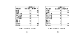
図2は、高周波電源の周波数を13.56MHz、第1コンデンサC1の容量を1500pF、コイルLのインダクタンスを1.8μHとし、各種食材の解凍をおこない、反射電力検知部による反射電力が常に最小になるように、第2コンデンサC2の容量調整をおこなったときの値(容量%)を示したものである。
図2から分かる通り、第3コンデンサC3を配置しなかった場合では、食材の種類や個数によって、解凍開始での第2コンデンサC2の容量%はそれぞれ異なり、更に、解凍終了で第2コンデンサC2の容量%は大きく減少方向に変化している。
第3コンデンサC3を配置した場合では、解凍開始、解凍終了での食材の種類や個数による第2コンデンサC2の容量%の変化は小さい。この結果から、第3コンデンサC3を配置することにより、食材解凍に伴う電極インピーダンスの変化率を小さくすることが可能であり、高周波電源20の周波数可変幅を小さく設定することができる。
図2から分かる通り、第3コンデンサC3を配置しなかった場合では、食材の種類や個数によって、解凍開始での第2コンデンサC2の容量%はそれぞれ異なり、更に、解凍終了で第2コンデンサC2の容量%は大きく減少方向に変化している。
第3コンデンサC3を配置した場合では、解凍開始、解凍終了での食材の種類や個数による第2コンデンサC2の容量%の変化は小さい。この結果から、第3コンデンサC3を配置することにより、食材解凍に伴う電極インピーダンスの変化率を小さくすることが可能であり、高周波電源20の周波数可変幅を小さく設定することができる。
整合器40は、高周波電源20と並列に接続された第1コンデンサC1の容量を多段切り替えもしくは連続変化させる、リレー等の接点手段から成る可変手段(図示しない)もしくはバリコン等を備えている。
なお、可変手段の具体的態様については、上記に限定されず、第1コンデンサC1の容量を多段切り替えもしくは連続変化させるものであれば如何なるものでもよく、また、可変手段によって、電極30と直列に接続されたコンデンサの容量を多段切り替えもしくは連続変化させてもよい。
なお、可変手段の具体的態様については、上記に限定されず、第1コンデンサC1の容量を多段切り替えもしくは連続変化させるものであれば如何なるものでもよく、また、可変手段によって、電極30と直列に接続されたコンデンサの容量を多段切り替えもしくは連続変化させてもよい。
制御部は、反射電力検知部によって検知された反射率を基に、被加熱物の解凍状態に応じて、第1コンデンサC1の容量を減少方向に切り替えるとともに、高周波電源20の周波数を調整し、インピーダンス整合を図るように設計されている。
以下に、本発明の第1実験例について説明する。
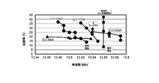
第1実験例では、リアクタンス回路50の第2コンデンサC2の容量を93pF、コイルLのインダクタンスを1.8μHとし、リアクタンス回路50のインピーダンス調整を、高周波電源20の周波数を調整することで行った。また、第3コンデンサC3の容量を400pFとした。また、高周波電源20は、反射電力検知部によって検知された反射率が40%を超えると保護機能により高周波出力が停止するように構成されている。また、一対の電極30間に配置される被解凍物(被加熱物)としては、冷凍柿(4個)を用いた。
図3は、解凍開始後、1分毎に周波数と反射率を測定した結果である。
解凍に伴う整合調整をしない場合として、第1コンデンサC1の容量を1500pFに設定し、高周波電源20の周波数を13.56MHzに固定して解凍を行った場合、3分程度で反射率が閾値(40%)を超え、高周波電源20の高周波発振が停止し、解凍が中断された。
また、第1コンデンサC1の容量の切り替え、および、高周波電源20の周波数を調整することによるリアクタンス回路50のインピーダンス調整を行った場合、第1コンデンサC1の容量を1500pFに設定して解凍を開始すると、解凍に伴い周波数が変化(13.53MHz→13.48MHz)することで反射率が閾値(40%)に達するまで7分かかり、周波数調整しない場合に比べて反射が閾値に到達するまでの時間を長くすることができた。
反射率が閾値に達したところで第1コンデンサC1の容量を1270pFに切り替えることで、反射率が約15%に低減し、同時に、周波数は変化(13.48MHz→13.55MHz)し、解凍開始時の周波数13.53MHzまでほぼ回復した。同様に、第1コンデンサC1の容量を1030pF、970pF、880pFと反射率に応じ適宜減少方向に切り替えることで、反射率を閾値以下に維持した状態で高周波印加が可能となり、解凍終了した。
反射率が閾値に達したところで第1コンデンサC1の容量を1270pFに切り替えることで、反射率が約15%に低減し、同時に、周波数は変化(13.48MHz→13.55MHz)し、解凍開始時の周波数13.53MHzまでほぼ回復した。同様に、第1コンデンサC1の容量を1030pF、970pF、880pFと反射率に応じ適宜減少方向に切り替えることで、反射率を閾値以下に維持した状態で高周波印加が可能となり、解凍終了した。
以上より、高周波誘電加熱装置10は、高周波電源20の周波数を可変調整することによるリアクタンス回路50のインピーダンス調整と、整合器40にリレー等の多段切り替えによって安価にインピーダンス整合を図ることができることが確認された。更に、整合器40におけるコンデンサ容量調整にバリコンを用いることにより、より高精度なインピーダンス調整を容易に達成することも可能である。また、高周波電源20の周波数を可変調整する際、整合器40におけるコンデンサ容量調整を併用することで、周波数可変幅を小さくすることが可能である。
つぎに、本発明の第2実施形態に係る高周波誘電加熱装置10について、図面に基づいて説明する。
高周波誘電加熱装置10は、図4に示すように、半導体式高周波電源20と、一対の電極30と、電極30と高周波電源20との間に接続されインピーダンス整合をとる整合器40と、高周波電源20と整合器40を接続する同軸ケーブル(図示しない)と、高周波電源20に反射する電力を検知する反射電力検知部(図示しない)と、各部を制御する制御部(図示しない)とを備え、対向配置された一対の電極30間に配置された冷凍食材を高周波誘電加熱によって解凍するものである。なお、高周波電源20は、反射電力検知部によって検知された反射率が所定の閾値を超えると保護機能により高周波出力を抑制又は停止するように構成されている。
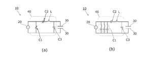
整合器40は、図4に示すように、高周波電源20と並列に接続された第1コンデンサC1と、電極30と並列に接続された第3コンデンサC3と、第1コンデンサC1と第3コンデンサC3の間に直列に接続されたコイルLおよび第2コンデンサC2を備えており、電極30と並列に第3コンデンサC3を整合器40内部に接続することにより、電極インピーダンスの変化を抑制する回路構成となっている。
第1コンデンサC1又は第2コンデンサC2の少なくとも一方は、容量可変手段(図示しない)を備え、解凍中、反射電力検知部で検知した反射電力を抑制するように容量調整可能である。上記コンデンサの容量調整は、図4(a)のバリコン駆動による連続調整式や図4(b)のリレーによる多段切り替え式であっても良い。また、第3コンデンサC3は、解凍中に逐次容量を可変調整することはないが、あらかじめ負荷に応じた最適値に設定するために、簡易的な容量可変機構を備えてあっても良い。
図4の回路構成において、高周波電源20の出力インピーダンスと整合器40からなる合成インピーダンスをZとすると、合成インピーダンスZは以下の式で表される。
Z=1/[{(1/R+jωC1)-1+j(ωL-1/ωC2)}-1+jωC3]
上記式中の各記号は、ω:角周波数、R:電源の出力インピーダンス(同軸ケーブルの抵抗)、L:コイルのリアクタンス、C1:容量可変の第1コンデンサの容量、C2:容量可変の第2コンデンサの容量、C3:第3コンデンサの容量である。
ここで、合成インピーダンスZの複素共役をZ’とすると、第1コンデンサC1又は第2コンデンサC2の容量可変幅で得られるZ’の範囲が、インピーダンス整合範囲であり、ω、R、L、C1、C2、C3の値によって、自由に設定可能である。
そして、第3コンデンサC3を所定の値に設定することによって、高周波電源20の出力インピーダンスと整合器40によって形成されるインピーダンス整合範囲の少なくとも抵抗は、前記出力インピーダンスより大きく(出力インピーダンスより大きい部分を含み)、リアクタンスの範囲は正より負が大となる。
Z=1/[{(1/R+jωC1)-1+j(ωL-1/ωC2)}-1+jωC3]
上記式中の各記号は、ω:角周波数、R:電源の出力インピーダンス(同軸ケーブルの抵抗)、L:コイルのリアクタンス、C1:容量可変の第1コンデンサの容量、C2:容量可変の第2コンデンサの容量、C3:第3コンデンサの容量である。
ここで、合成インピーダンスZの複素共役をZ’とすると、第1コンデンサC1又は第2コンデンサC2の容量可変幅で得られるZ’の範囲が、インピーダンス整合範囲であり、ω、R、L、C1、C2、C3の値によって、自由に設定可能である。
そして、第3コンデンサC3を所定の値に設定することによって、高周波電源20の出力インピーダンスと整合器40によって形成されるインピーダンス整合範囲の少なくとも抵抗は、前記出力インピーダンスより大きく(出力インピーダンスより大きい部分を含み)、リアクタンスの範囲は正より負が大となる。
制御部は、反射電力検知部によって検知された反射率を基に、被加熱物の解凍状態に応じて、第1コンデンサC1又は第2コンデンサC2の少なくとも一方の容量を減少方向に切り替えることによって、インピーダンス整合を図るように設計されている。制御部は、解凍中に第3コンデンサC3の容量を可変調整することはない。
以下に、本発明の第2実験例について説明する。
図2(a)は、高周波電源20の周波数=13.56MHz、高周波電源20の出力インピーダンス=50Ω、第1コンデンサC1の容量C1=1500pF、容量可変の第2コンデンサC2の容量C2=25~250pF、コイルLのインダクタンスL=1.8μHとし、各種食材の解凍をおこない、反射電力検知部による反射電力が常に最小になるように、第2コンデンサC2の容量調整をおこなったときの値(容量%)を示している。
第3コンデンサC3を接続しない場合、解凍開始でのC2容量%は食材の種類や個数によってそれぞれ異なっており、解凍終了でのC2容量%は減少方向に大きく変化している。すなわち、第2コンデンサC2の容量可変幅を大きくしなければ、インピーダンス整合をおこなうことは困難であり、整合器40の簡素化、小型化を図ることはできない。
図2(b)は、上記回路構成に加えて電極30と並列に容量400pFの第3コンデンサC3を接続し、各種食材の解凍をおこない、反射電力検知部による反射電力が常に最小になるように、第2コンデンサC2の容量調整をおこなったときの値(容量%)を示したものである。第2コンデンサC2の容量%を大きく変化させることなく、各種食材の解凍が可能であり、第2コンデンサC2の容量可変幅を小さくした整合器40の簡素化、小型化を図ることができる。
第3コンデンサC3を接続しない場合、解凍開始でのC2容量%は食材の種類や個数によってそれぞれ異なっており、解凍終了でのC2容量%は減少方向に大きく変化している。すなわち、第2コンデンサC2の容量可変幅を大きくしなければ、インピーダンス整合をおこなうことは困難であり、整合器40の簡素化、小型化を図ることはできない。
図2(b)は、上記回路構成に加えて電極30と並列に容量400pFの第3コンデンサC3を接続し、各種食材の解凍をおこない、反射電力検知部による反射電力が常に最小になるように、第2コンデンサC2の容量調整をおこなったときの値(容量%)を示したものである。第2コンデンサC2の容量%を大きく変化させることなく、各種食材の解凍が可能であり、第2コンデンサC2の容量可変幅を小さくした整合器40の簡素化、小型化を図ることができる。
図5は、高周波電源20の周波数=13.56MHz、高周波電源20の出力インピーダンス=50Ω、第2コンデンサC2の容量C2=95pF、コイルLのインダクタンスL=1.8μH、容量可変の第1コンデンサC1の容量C1=150~1500pF、第3コンデンサC3の容量C3=400pFとし、各種食材の解凍をおこない、反射電力検知部による反射電力が常に最小になるように、第1コンデンサC1の容量調整をおこなったときのC1の値(容量%)を示している。第3コンデンサC3を接続することにより、第1コンデンサC1の容量可変幅を小さく設定することが可能であり、整合器40の簡素化、小型化を図ることができる。
図6は、図10(a)の回路構成において、高周波電源20と整合器40の合成インピーダンスをZとし、Z=R/(1+ω2R2C1
2)+j{(ωL-1/ωC2)-ωR2C1/(1+ω2R2C1
2)}の複素共役Z’で得られるインピーダンス整合範囲を示している。
ただし、角周波数ω=13.56MHz、高周波電源20の出力インピーダンスR=50Ω、コイルLのリアクタンスL=1.8μH、容量可変の第1コンデンサC1の容量C1=150~1500pF、容量可変の第2コンデンサC2の容量C2=25~250pFとする。
Z’で得られるインピーダンス整合範囲は、高周波電源20の出力インピーダンスR=50Ω(規格化インピーダンス1)より小さい範囲に限定されており、それより大きな抵抗負荷に対してはインピーダンス整合不能である。
ただし、角周波数ω=13.56MHz、高周波電源20の出力インピーダンスR=50Ω、コイルLのリアクタンスL=1.8μH、容量可変の第1コンデンサC1の容量C1=150~1500pF、容量可変の第2コンデンサC2の容量C2=25~250pFとする。
Z’で得られるインピーダンス整合範囲は、高周波電源20の出力インピーダンスR=50Ω(規格化インピーダンス1)より小さい範囲に限定されており、それより大きな抵抗負荷に対してはインピーダンス整合不能である。
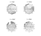
図7は、図4の回路構成において、高周波電源20の出力インピーダンスと整合器40からなる合成インピーダンスをZとすると、Z=1/[{(1/R+jωC1)-1+j(ωL-1/ωC2)}-1+jωC3}]の複素共役Z’で得られるインピーダンス整合範囲を示している。
ただし、角周波数ω=13.56MHz、電源の出力インピーダンスR=50Ω、コイルLのリアクタンスL=1.8μH、容量可変の第1コンデンサC1の容量C1=150~1500pF、容量可変の第2コンデンサC2の容量C2=25~250pF、第3コンデンサC3の容量C3=50pF、200pF、400pF、600pFとする。
電極30と並列に第3コンデンサC3を接続し、その値を増加することによって、前述した図6に示す例のZ’で得られるインピーダンス整合範囲は、反時計周りに回転し、Z’の抵抗は電源の出力インピーダンスR=50Ω(規格化インピーダンス1)より大きい範囲に拡大した。リアクタンスの範囲は、第3コンデンサC3の容量C3=200pF、400pFでは正より負が大きく、C3=600pFでは正より負が小さくなった。このように、電極30と並列に第3コンデンサC3を接続することによって、冷凍食材の解凍に特化した整合範囲を得ることができる。
ただし、角周波数ω=13.56MHz、電源の出力インピーダンスR=50Ω、コイルLのリアクタンスL=1.8μH、容量可変の第1コンデンサC1の容量C1=150~1500pF、容量可変の第2コンデンサC2の容量C2=25~250pF、第3コンデンサC3の容量C3=50pF、200pF、400pF、600pFとする。
電極30と並列に第3コンデンサC3を接続し、その値を増加することによって、前述した図6に示す例のZ’で得られるインピーダンス整合範囲は、反時計周りに回転し、Z’の抵抗は電源の出力インピーダンスR=50Ω(規格化インピーダンス1)より大きい範囲に拡大した。リアクタンスの範囲は、第3コンデンサC3の容量C3=200pF、400pFでは正より負が大きく、C3=600pFでは正より負が小さくなった。このように、電極30と並列に第3コンデンサC3を接続することによって、冷凍食材の解凍に特化した整合範囲を得ることができる。
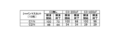
図8は、高周波電源20の周波数=13.56MHz、高周波電源20の出力インピーダンス=50Ω、コイルLのインダクタンスL=1.8μH、バリコン第1コンデンサC1の容量C1=150~1500pF、バリコン第2コンデンサC2の容量C2=25~250pF、第3コンデンサC3の容量C3=200pF、400pFとし、-40℃の冷凍シャインマスカット15粒(厚さ28mm)を出力50W、解凍時間15分で解凍をおこない、反射電力検知部による反射電力が常に最小になるように、バリコンC1、C2のコンデンサ容量をサーボモーターで逐次自動調整したときのC1、C2の値(容量%)を示している。
第3コンデンサC3が接続されていない状態では、解凍に伴いバリコンC1、C2の値は大きく減少変化しているが、第3コンデンサC3を接続することによりバリコンC1、C2の変化は抑制され、C3=200pFよりC3=400pFの方がバリコンC1、C2の変化抑制の効果は大きかった。
第3コンデンサC3が接続されていない状態では、解凍に伴いバリコンC1、C2の値は大きく減少変化しているが、第3コンデンサC3を接続することによりバリコンC1、C2の変化は抑制され、C3=200pFよりC3=400pFの方がバリコンC1、C2の変化抑制の効果は大きかった。
図9は、高周波電源20の周波数=13.56MHz、高周波電源20の出力インピーダンス=50Ω、コイルLのインダクタンスL=1.8μH、バリコン第1コンデンサC1の容量C1=150~1500pF、バリコン第2コンデンサC2の容量C2=25~250pF、第3コンデンサC3の容量C3=200pF、400pFとし、-40℃の冷凍マンゴー(厚さ85mm)を出力200W、解凍時間15分で解凍をおこない、反射電力検知部による反射電力が常に最小になるように、バリコンC1、C2のコンデンサ容量をサーボモーターで逐次自動調整したときのC1、C2の値(容量%)を示している。
第3コンデンサC3が接続されていない状態では、解凍に伴いバリコンC1、C2の値は大きく減少変化しているが、C3=200pFを接続した状態では、バリコンC1、C2の変化は抑制されている。C3=400pFを接続した状態では、自動インピーダンス整合できなかった。
第3コンデンサC3が接続されていない状態では、解凍に伴いバリコンC1、C2の値は大きく減少変化しているが、C3=200pFを接続した状態では、バリコンC1、C2の変化は抑制されている。C3=400pFを接続した状態では、自動インピーダンス整合できなかった。
以上より、高周波誘電加熱装置10は、整合器40に電極30と並列に第3コンデンサC3を接続することによって、食材解凍に伴う電極インピーダンスの変化を抑制し、整合器40の簡素化、小型化を図りながらインピーダンス整合が可能であることが確認された。
このとき、第3コンデンサC3のコンデンサ容量の値が大きい方が、電極インピーダンスの変化抑制に効果的であるが、冷凍食材が厚肉の場合、整合が困難になることもあるため、食材に応じて、最適なC3の値を設定することが好ましい。
このとき、第3コンデンサC3のコンデンサ容量の値が大きい方が、電極インピーダンスの変化抑制に効果的であるが、冷凍食材が厚肉の場合、整合が困難になることもあるため、食材に応じて、最適なC3の値を設定することが好ましい。
以上、本発明の実施形態を詳述したが、本発明は上記実施形態に限定されるものではなく、特許請求の範囲に記載された本発明を逸脱することなく種々の設計変更を行なうことが可能である。
例えば、上述した実施形態では、高周波誘電加熱装置が、冷凍食材を高周波誘電加熱によって解凍するものとして説明したが、食材以外に血液や動植物といった生体などの解凍であっても同様の効果を得ることは可能であり、また、高周波誘電加熱装置の用途は、被加熱物を加熱するものであればよく、冷凍食材の解凍に限定されない。
また、上述した実施形態に加えて、整合器のインピーダンス情報(例えば、第1コンデンサの状態など)を監視モニタなどに出力するインピーダンス情報出力部を設けてもよい。この場合、整合器のインピーダンス情報出力部から食材インピーダンスの正確な情報を簡単に得ることが可能になり、対象とする被加熱物に絞り込んだ整合器のパラメータを設定したり、その結果に基づき整合器の簡素化を図ることができる。
本発明の半導体式高周波誘電加熱装置は、冷凍食品等の急速解凍に好適であるばかりでなく、工業用の誘電加熱装置としても広く適用でき、また、家庭用または業務用の卓上型解凍装置(電子レンジ)や冷蔵庫等に組み込んで用いることもできる等、産業上の利用可能性が高い。
Claims (8)
- 高周波電源と、対向して配置された一対の電極と、前記電極と高周波電源との間に接続され被加熱物の加熱で生じる反射電力を検出する反射電力検出手段と、反射電力を調整するインピーダンス整合器からなる高周波誘電加熱装置であって、
前記整合器は、前記高周波電源と並列に接続されたコンデンサと、前記電極に直列に接続された少なくともリアクタンス調整可能なコンデンサまたはコイルの少なくとも一方を備え、
前記高周波電源は、周波数を可変に構成されていることを特徴とする高周波誘電加熱装置。 - 前記高周波電源は、半導体式高周波電源であることを特徴とする請求項1に記載の高周波誘電加熱装置。
- 前記整合器は、前記高周波電源と並列に接続されたコンデンサまたは前記電極と直列に接続されたコンデンサの少なくとも一方の容量を多段切り替えもしくは連続変化させる可変手段を備えることを特徴とする請求項1または請求項2に記載の高周波誘電加熱装置。
- 前記整合器は、前記電極と並列に接続されたコンデンサを有することを特徴とする請求項1乃至請求項3のいずれかに記載の高周波誘電加熱装置。
- 半導体式高周波電源と、対向して配置された一対の電極と、インピーダンス整合器からなる高周波誘電加熱装置であって、
前記整合器は、前記高周波電源と並列に接続された第1コンデンサと、前記電極と並列に接続された第3コンデンサと、前記第1コンデンサと前記第3コンデンサの間に直列に接続されたコイルおよび第2コンデンサを備えていることを特徴とする高周波誘電加熱装置。 - 前記第1コンデンサ又は前記第2コンデンサの少なくとも一方は容量可変手段を備えていることを特徴とする請求項5に記載の高周波誘電加熱装置。
- 前記高周波電源の出力インピーダンスと前記整合器によって形成されるインピーダンス整合範囲について、前記整合範囲の抵抗は前記出力インピーダンスより大きい部分を含み、且つ、リアクタンスの範囲は正より負が大になるように設定されていることを特徴とする請求項5又は6に記載の高周波誘電加熱装置。
- 前記高周波誘電加熱装置に整合器のインピーダンス情報を出力するインピーダンス情報出力部を備える請求項1又は5に記載の高周波誘電加熱装置。
Priority Applications (5)
| Application Number | Priority Date | Filing Date | Title |
|---|---|---|---|
| KR1020237006581A KR20230035682A (ko) | 2015-07-03 | 2016-06-03 | 고주파 유전 가열 장치 |
| CN201680034699.0A CN107710869B (zh) | 2015-07-03 | 2016-06-03 | 高频感应加热装置 |
| EP16821144.9A EP3322258A4 (en) | 2015-07-03 | 2016-06-03 | DIELECTRIC HIGH FREQUENCY HEATING DEVICE |
| KR1020177036357A KR20180023904A (ko) | 2015-07-03 | 2016-06-03 | 고주파 유전 가열 장치 |
| US15/844,824 US20180110098A1 (en) | 2015-07-03 | 2017-12-18 | High-frequency dielectric heating device |
Applications Claiming Priority (8)
| Application Number | Priority Date | Filing Date | Title |
|---|---|---|---|
| JP2015-134647 | 2015-07-03 | ||
| JP2015-134646 | 2015-07-03 | ||
| JP2015134646 | 2015-07-03 | ||
| JP2015134647 | 2015-07-03 | ||
| JP2016-111798 | 2016-06-03 | ||
| JP2016111797A JP6838290B2 (ja) | 2015-07-03 | 2016-06-03 | 高周波誘電加熱装置 |
| JP2016-111797 | 2016-06-03 | ||
| JP2016111798A JP6838291B2 (ja) | 2015-07-03 | 2016-06-03 | 半導体式高周波誘電加熱装置 |
Related Child Applications (1)
| Application Number | Title | Priority Date | Filing Date |
|---|---|---|---|
| US15/844,824 Continuation US20180110098A1 (en) | 2015-07-03 | 2017-12-18 | High-frequency dielectric heating device |
Publications (1)
| Publication Number | Publication Date |
|---|---|
| WO2017006673A1 true WO2017006673A1 (ja) | 2017-01-12 |
Family
ID=57685414
Family Applications (1)
| Application Number | Title | Priority Date | Filing Date |
|---|---|---|---|
| PCT/JP2016/066624 Ceased WO2017006673A1 (ja) | 2015-07-03 | 2016-06-03 | 高周波誘電加熱装置 |
Country Status (2)
| Country | Link |
|---|---|
| KR (1) | KR20230035682A (ja) |
| WO (1) | WO2017006673A1 (ja) |
Cited By (10)
| Publication number | Priority date | Publication date | Assignee | Title |
|---|---|---|---|---|
| JP2019032963A (ja) * | 2017-08-07 | 2019-02-28 | シャープ株式会社 | 高周波解凍装置 |
| JP2019046727A (ja) * | 2017-09-06 | 2019-03-22 | シャープ株式会社 | 高周波加熱システム |
| WO2019077858A1 (ja) * | 2017-10-18 | 2019-04-25 | 東洋製罐グループホールディングス株式会社 | 高周波誘電加熱装置 |
| JP2019075363A (ja) * | 2017-10-18 | 2019-05-16 | 東洋製罐グループホールディングス株式会社 | 高周波誘電加熱装置 |
| JP2021022432A (ja) * | 2019-07-24 | 2021-02-18 | シャープ福山セミコンダクター株式会社 | 高周波加熱装置 |
| JP2022516295A (ja) * | 2019-01-04 | 2022-02-25 | 海尓智家股▲フン▼有限公司 | 電磁波生成システム及び電磁波生成システムを有する加熱装置 |
| CN115996494A (zh) * | 2021-10-18 | 2023-04-21 | 青岛海尔电冰箱有限公司 | 用于加热装置的控制方法及加热装置 |
| WO2023166594A1 (ja) * | 2022-03-02 | 2023-09-07 | 三菱電機株式会社 | 高周波誘電加熱装置 |
| JP2025508636A (ja) * | 2022-03-17 | 2025-04-04 | 湖北中烟工業有限責任公司 | 高周波加熱喫煙具のインピーダンスマッチング方法、装置及び電子機器 |
| TWI893854B (zh) * | 2024-06-20 | 2025-08-11 | 國立虎尾科技大學 | 一種具高週波電流同調裝置的控制熱加工系統及該裝置 |
Citations (4)
| Publication number | Priority date | Publication date | Assignee | Title |
|---|---|---|---|---|
| JPS56102096A (en) * | 1980-01-16 | 1981-08-15 | Matsushita Electric Industrial Co Ltd | High frequency heater |
| JPS58107161A (ja) * | 1981-12-16 | 1983-06-25 | Matsushita Electric Ind Co Ltd | 高周波解凍機 |
| JP2005056781A (ja) * | 2003-08-07 | 2005-03-03 | Matsushita Electric Ind Co Ltd | 高周波加熱装置 |
| WO2012169337A1 (ja) * | 2011-06-06 | 2012-12-13 | 三菱電機株式会社 | 高周波電源発生装置 |
Family Cites Families (1)
| Publication number | Priority date | Publication date | Assignee | Title |
|---|---|---|---|---|
| JP3122005B2 (ja) | 1995-03-16 | 2001-01-09 | シャープ株式会社 | 高周波解凍装置 |
-
2016
- 2016-06-03 WO PCT/JP2016/066624 patent/WO2017006673A1/ja not_active Ceased
- 2016-06-03 KR KR1020237006581A patent/KR20230035682A/ko not_active Ceased
Patent Citations (4)
| Publication number | Priority date | Publication date | Assignee | Title |
|---|---|---|---|---|
| JPS56102096A (en) * | 1980-01-16 | 1981-08-15 | Matsushita Electric Industrial Co Ltd | High frequency heater |
| JPS58107161A (ja) * | 1981-12-16 | 1983-06-25 | Matsushita Electric Ind Co Ltd | 高周波解凍機 |
| JP2005056781A (ja) * | 2003-08-07 | 2005-03-03 | Matsushita Electric Ind Co Ltd | 高周波加熱装置 |
| WO2012169337A1 (ja) * | 2011-06-06 | 2012-12-13 | 三菱電機株式会社 | 高周波電源発生装置 |
Cited By (19)
| Publication number | Priority date | Publication date | Assignee | Title |
|---|---|---|---|---|
| JP2019032963A (ja) * | 2017-08-07 | 2019-02-28 | シャープ株式会社 | 高周波解凍装置 |
| JP2019046727A (ja) * | 2017-09-06 | 2019-03-22 | シャープ株式会社 | 高周波加熱システム |
| WO2019077858A1 (ja) * | 2017-10-18 | 2019-04-25 | 東洋製罐グループホールディングス株式会社 | 高周波誘電加熱装置 |
| JP2019075363A (ja) * | 2017-10-18 | 2019-05-16 | 東洋製罐グループホールディングス株式会社 | 高周波誘電加熱装置 |
| JP2019075361A (ja) * | 2017-10-18 | 2019-05-16 | 東洋製罐グループホールディングス株式会社 | 高周波誘電加熱装置 |
| JP7210923B2 (ja) | 2017-10-18 | 2023-01-24 | 東洋製罐グループホールディングス株式会社 | 高周波誘電加熱装置 |
| JP7192248B2 (ja) | 2017-10-18 | 2022-12-20 | 東洋製罐グループホールディングス株式会社 | 高周波誘電加熱装置 |
| AU2019418574B2 (en) * | 2019-01-04 | 2022-09-15 | Haier Smart Home Co., Ltd. | Electromagnetic wave generating system and heating apparatus having same |
| EP3908082A4 (en) * | 2019-01-04 | 2022-03-09 | Haier Smart Home Co., Ltd. | SYSTEM FOR GENERATION OF ELECTROMAGNETIC WAVES AND HEATING DEVICE THEREOF |
| JP2022516295A (ja) * | 2019-01-04 | 2022-02-25 | 海尓智家股▲フン▼有限公司 | 電磁波生成システム及び電磁波生成システムを有する加熱装置 |
| US11889610B2 (en) | 2019-01-04 | 2024-01-30 | Haier Smart Home Co., Ltd. | Electromagnetic wave generating system and heating device with electromagnetic wave generating system |
| JP2021022432A (ja) * | 2019-07-24 | 2021-02-18 | シャープ福山セミコンダクター株式会社 | 高周波加熱装置 |
| JP7248532B2 (ja) | 2019-07-24 | 2023-03-29 | シャープセミコンダクターイノベーション株式会社 | 高周波加熱装置 |
| CN115996494A (zh) * | 2021-10-18 | 2023-04-21 | 青岛海尔电冰箱有限公司 | 用于加热装置的控制方法及加热装置 |
| WO2023166594A1 (ja) * | 2022-03-02 | 2023-09-07 | 三菱電機株式会社 | 高周波誘電加熱装置 |
| JP7415101B1 (ja) * | 2022-03-02 | 2024-01-16 | 三菱電機株式会社 | 高周波誘電加熱装置 |
| JP2025508636A (ja) * | 2022-03-17 | 2025-04-04 | 湖北中烟工業有限責任公司 | 高周波加熱喫煙具のインピーダンスマッチング方法、装置及び電子機器 |
| JP7774157B2 (ja) | 2022-03-17 | 2025-11-20 | 湖北中烟工業有限責任公司 | 高周波加熱喫煙具のインピーダンスマッチング方法、装置及び電子機器 |
| TWI893854B (zh) * | 2024-06-20 | 2025-08-11 | 國立虎尾科技大學 | 一種具高週波電流同調裝置的控制熱加工系統及該裝置 |
Also Published As
| Publication number | Publication date |
|---|---|
| KR20230035682A (ko) | 2023-03-14 |
Similar Documents
| Publication | Publication Date | Title |
|---|---|---|
| WO2017006673A1 (ja) | 高周波誘電加熱装置 | |
| CN107710869B (zh) | 高频感应加热装置 | |
| JP6838290B2 (ja) | 高周波誘電加熱装置 | |
| JP6998668B2 (ja) | 集中誘導性整合ネットワークを備える解凍装置およびその作動方法 | |
| JP6998669B2 (ja) | 解凍動作の完了を検出するための装置および方法 | |
| JP6818725B2 (ja) | キャビティ内シャントコンデンサを備えた無線周波数加熱解凍装置 | |
| KR102196228B1 (ko) | Rf 가열 시스템에서의 해동 동작을 위한 장치 및 방법 | |
| JP6541540B2 (ja) | プラズマ処理装置のインピーダンス整合のための方法 | |
| CN110521912B (zh) | 具有质量估计的解冻设备和其操作方法 | |
| JP6619818B2 (ja) | パルス高周波電源のインピーダンス整合方法および装置 | |
| US10818477B2 (en) | Impedance matching between loads and power generators | |
| JP4887197B2 (ja) | 高周波装置 | |
| JP6741304B2 (ja) | インピーダンス回路網調整のための位相検出を備えたrf加熱システム | |
| CN108924982A (zh) | 解冻设备及其操作方法 | |
| US20160204757A1 (en) | Impedance matching method and impedance matching system | |
| JP2018521494A (ja) | 高周波加熱システム | |
| US11515123B2 (en) | Apparatus and system for modulated plasma systems | |
| JP2008181846A5 (ja) | ||
| JP2005056781A (ja) | 高周波加熱装置 | |
| JP2020102438A (ja) | 解凍装置を用いて解凍動作を実行する方法 | |
| US20190318912A1 (en) | Plasma processing apparatus | |
| JP6838291B2 (ja) | 半導体式高周波誘電加熱装置 | |
| KR20180080632A (ko) | 플라즈마 생성을 위한 전력 공급 장치 | |
| JP6603586B2 (ja) | プラズマ処理方法及びプラズマ処理装置 | |
| JP2002056964A (ja) | 誘電加熱装置 |
Legal Events
| Date | Code | Title | Description |
|---|---|---|---|
| 121 | Ep: the epo has been informed by wipo that ep was designated in this application |
Ref document number: 16821144 Country of ref document: EP Kind code of ref document: A1 |
|
| ENP | Entry into the national phase |
Ref document number: 20177036357 Country of ref document: KR Kind code of ref document: A |
|
| NENP | Non-entry into the national phase |
Ref country code: DE |
|
| WWE | Wipo information: entry into national phase |
Ref document number: 2016821144 Country of ref document: EP |