WO2017006677A1 - Article absorbant et son procédé de fabrication - Google Patents
Article absorbant et son procédé de fabrication Download PDFInfo
- Publication number
- WO2017006677A1 WO2017006677A1 PCT/JP2016/066755 JP2016066755W WO2017006677A1 WO 2017006677 A1 WO2017006677 A1 WO 2017006677A1 JP 2016066755 W JP2016066755 W JP 2016066755W WO 2017006677 A1 WO2017006677 A1 WO 2017006677A1
- Authority
- WO
- WIPO (PCT)
- Prior art keywords
- flap
- sheet
- main body
- skin
- fold line
- Prior art date
- Legal status (The legal status is an assumption and is not a legal conclusion. Google has not performed a legal analysis and makes no representation as to the accuracy of the status listed.)
- Ceased
Links
Images





Classifications
-
- A—HUMAN NECESSITIES
- A61—MEDICAL OR VETERINARY SCIENCE; HYGIENE
- A61F—FILTERS IMPLANTABLE INTO BLOOD VESSELS; PROSTHESES; DEVICES PROVIDING PATENCY TO, OR PREVENTING COLLAPSING OF, TUBULAR STRUCTURES OF THE BODY, e.g. STENTS; ORTHOPAEDIC, NURSING OR CONTRACEPTIVE DEVICES; FOMENTATION; TREATMENT OR PROTECTION OF EYES OR EARS; BANDAGES, DRESSINGS OR ABSORBENT PADS; FIRST-AID KITS
- A61F13/00—Bandages or dressings; Absorbent pads
- A61F13/15—Absorbent pads, e.g. sanitary towels, swabs or tampons for external or internal application to the body; Supporting or fastening means therefor; Tampon applicators
-
- A—HUMAN NECESSITIES
- A61—MEDICAL OR VETERINARY SCIENCE; HYGIENE
- A61F—FILTERS IMPLANTABLE INTO BLOOD VESSELS; PROSTHESES; DEVICES PROVIDING PATENCY TO, OR PREVENTING COLLAPSING OF, TUBULAR STRUCTURES OF THE BODY, e.g. STENTS; ORTHOPAEDIC, NURSING OR CONTRACEPTIVE DEVICES; FOMENTATION; TREATMENT OR PROTECTION OF EYES OR EARS; BANDAGES, DRESSINGS OR ABSORBENT PADS; FIRST-AID KITS
- A61F13/00—Bandages or dressings; Absorbent pads
- A61F13/15—Absorbent pads, e.g. sanitary towels, swabs or tampons for external or internal application to the body; Supporting or fastening means therefor; Tampon applicators
- A61F13/45—Absorbent pads, e.g. sanitary towels, swabs or tampons for external or internal application to the body; Supporting or fastening means therefor; Tampon applicators characterised by the shape
- A61F13/49—Absorbent pads, e.g. sanitary towels, swabs or tampons for external or internal application to the body; Supporting or fastening means therefor; Tampon applicators characterised by the shape specially adapted to be worn around the waist, e.g. diapers, nappies
Definitions
- the present invention relates to an absorbent article and a method for manufacturing the absorbent article.
- Patent Documents 1 to 4 disclose open-type disposable diapers. In the diapers described in these patent documents, folding of a flap or a tape is also described.
- An object of the present invention is to provide an absorbent article that can prompt a worker to perform a sufficient flap unfolding operation.
- the main invention for achieving the above object is that the skin-side sheet on the skin side constituting the main body and the base end region are joined to the skin-side sheet, and the region outside the base end region forms a side flap.
- the base sheet of the flap sheet has a recessed portion forming region in which a recessed portion is formed, and the skin side sheet and the flap sheet are joined in the recessed portion forming region and folded back.
- the skin-side surface of the side flap and the skin-side surface of the main body are temporarily fixed by a temporary fixing portion formed in a region overlapping with the recess forming region in the thickness direction. It is an absorbent article.
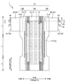
- FIG. 1 is a plan view of the developed absorbent article 1 as seen from the skin side.
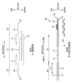
- 2A is an exploded explanatory view taken along the line AA in FIG.
- FIG. 2B is an enlarged explanatory view taken along the line BB in FIG.
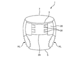
- FIG. 3 is an explanatory diagram of the absorbent article 1 in a worn state.
- 4A and 4B are explanatory diagrams of the fastening tape 30 before unfolding.
- FIG. 4C is an explanatory diagram illustrating a part of the fastening tape 30 in the same state as FIG.
- FIG. 5A is an explanatory diagram of a fold line portion of the side flap 20.
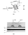
- FIG. 5B is an explanatory diagram of the absorbent article 1 in a state where the side flaps 20 are folded and temporarily fixed (temporarily fixed state).
- FIG. 5C is an enlarged explanatory view of the CC section of FIG. 5B.
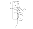
- FIG. 6 is an explanatory diagram of a state during the flap unfolding operation.
- FIG. 7A is a transmission plan view of the adhesive application range of the first temporary fixing part 51.
- FIG. 7B is a transmission plan view of the adhesive application range of the second temporary fixing portion 52.
- 8A to 8C are explanatory diagrams of the joining process of the side flap sheet 21.
- FIG. FIG. 9A is an explanatory diagram of a recess formation region of the base end region 21A.
- FIG. 9B is an enlarged cross-sectional view of the bonding surface in the recess formation region.
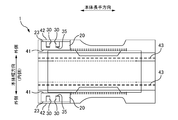
- FIG. 10 is an explanatory diagram of the main body fold line portion 43 when the absorbent article 1 is packaged.
- FIG. 11A is an explanatory diagram of a main body fold line portion 43 of a modification.
- FIG. 11B is an explanatory diagram of folding of the side flap 20 by the main body folding line portion 43 of the modification.
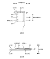
- FIG. 12A is an explanatory diagram of a temporarily fixed state in the second embodiment.
- FIG. 12B is an enlarged explanatory view of the DD cross section of FIG. 12A.
- the base end region there is a recess forming region in which a recess is formed, the skin side sheet and the flap sheet are joined in the recess forming region, and the skin side surface of the folded back side flap.
- the absorbent article is characterized in that the skin side surface of the main body part is temporarily fixed by a temporary fixing part formed in a region overlapping with the concave portion forming region in the thickness direction. According to such an absorbent article, it is possible to prompt the operator to perform a sufficient flap unfolding operation.
- the skin side sheet has less basis weight than the flap sheet. This is particularly effective in such a case.
- the temporary fixing portion is formed along a longitudinal direction of the main body with a predetermined width, and is arranged so that the concave portion formed in a line crosses the temporary fixing portion when viewed from the thickness direction. It is desirable. Thereby, the peeling origin of a temporary fix part can be formed so that a temporary fix part may be crossed.
- the side flap is folded by a first fold line portion on the side of the flap tip and a second fold line portion on the side of the main body, and the side flap is folded by the second fold line portion.
- the skin-side surface and the skin-side surface of the main body portion are temporarily fixed by the temporary fixing portion, and the non-skin-side surfaces of the side flaps folded back by the first folding line portion are the temporary surfaces. It is desirable to be temporarily fixed by a temporary fixing part different from the fixing part. Thereby, the operation
- the bonding force of the another temporary fixing portion is stronger than the bonding force of the temporary fixing portion that temporarily fixes the skin side surface of the side flap and the skin side surface of the main body portion. As a result, the operator can be encouraged to perform a sufficient flap unfolding operation.
- the main body fold line part along the main body longitudinal direction, the main body part is further folded from the state where the side flaps are folded, and in the state where the side flaps are temporarily fixed while unfolding the main body fold line part, It is desirable that the main body fold line portion is located on the inner side in the main body width direction than the fastening tape. Thereby, it becomes difficult to fold the main body fold line portion on the fastening tape.
- the main body fold line portion is preferably located on the inner side in the main body width direction with respect to the first fold line portion. This makes it difficult for the side flaps to be excessively folded.
- the main body fold line portion is located between the first fold line portion and the tape front end portion of the fastening tape. Therefore, it can suppress that the tape front-end
- At least two fastening tapes are provided at the flap front ends of the side flaps, and the fastening tapes are folded by fixing the fastening surfaces of the fastening tapes to the side flaps. It is desirable that a temporary fixing portion for folding is formed along the longitudinal direction of the body on the outer side of the folded two fastening tapes in the longitudinal direction of the body. This makes it easier to put a finger in the area between the two fastening tapes when the flap tip is gripped and the flap unfolding operation is performed.
- an absorbent article comprising: a skin side sheet on the skin side constituting the main body part; and a flap sheet in which a base end region is joined to the skin side sheet and a region outside the base end region forms a side flap.
- a recessed portion forming region having a recessed portion in the proximal end region of the flap sheet; and a skin side surface of the folded side flap and a skin side surface of the main body portion.
- the manufacturing method of becomes clear. According to such a method for manufacturing an absorbent article, it is possible to manufacture an absorbent article that can prompt the operator to perform a sufficient flap unfolding operation.
- FIG. 1 is a plan view of the developed absorbent article 1 as seen from the skin side.
- 2A is an exploded explanatory view taken along the line AA in FIG.
- FIG. 2B is an enlarged explanatory view taken along the line BB in FIG.
- FIG. 3 is an explanatory diagram of the absorbent article 1 in a worn state.
- the side that should be positioned on the skin side of the wearer may be referred to as “skin side”, and the side that should be positioned on the non-skin side of the wearer may be referred to as “non-skin side”.
- the longitudinal direction of the main body 10 of the elongated absorbent article 1 may be referred to as “main body longitudinal direction”, and the width direction of the main body 10 may be referred to as “main body width direction”.
- the center side of the absorbent article 1 may be referred to as “inside” and the opposite side may be referred to as “outside”.
- each sheet may be referred to as a “base end portion”, and an outer end portion of each sheet may be referred to as a “leading end portion”.
- a direction orthogonal to the longitudinal direction of the main body and the width direction of the main body may be referred to as a “thickness direction”.
- the side of the top sheet 12 when viewed from the absorbent core 11 may be referred to as “front side”, and the opposite side may be referred to as “back side”.
- the “skin side” becomes “front side”, but as described later, the “non-skin side” may become “front side” when the sheet is folded. .
- the absorbent article 1 is an article that absorbs and retains the excretion fluid (for example, urine) of the wearer.
- the absorbent article 1 of this embodiment is a disposable diaper for adults.
- the absorbent article 1 may be a baby diaper or a sanitary napkin.
- the absorbent article 1 has a front part 3, a crotch part 5, and a rear part 7, as shown in FIG.
- the front part 3 is a part which will be located in a wearer's front side (abdominal side).
- the rear part 7 is a part which will be located in a wearer's rear side (buttock side, back side).
- the crotch part 5 is a part that is located between the front part 3 and the rear part 7.
- the absorbent article 1 has a main body 10, a side flap 20, and a fastening tape 30. Moreover, the absorbent article of this embodiment is bonded to the skin side sheet
- a region outside the region 21 ⁇ / b> A has a side flap sheet 21 constituting the side flap 20.
- the main body portion 10 is a belt-like portion located in the central portion of the absorbent article 1 in the main body width direction, and is configured along the longitudinal direction across the front portion 3, the crotch portion 5, and the rear portion 7.
- the main body 10 has an absorption region 10A and a wing region 10B.
- the absorption region 10 ⁇ / b> A is a region that absorbs and holds liquid, and is formed at the center of the main body 10.
- the wing region 10B is a region outside the absorption region 10A.
- Side flaps 20 are formed outside the rear portion 7 of the wing region 10B.
- the crotch part 5 of the wing region 10B is provided with a stretchable part 15 (see FIG. 1) that constitutes a leg gather LG (see FIG. 3) that prevents leakage of urine and feces from the wearer's legs.
- the main body 10 has an absorbent core 11, a top sheet 12, and a back sheet 13.
- the absorptive core 11 is a member that absorbs and holds liquid (excretion fluid).
- the top sheet 12 is a liquid-permeable sheet member disposed on the skin side of the absorbent core 11.
- the back sheet 13 is a liquid-impermeable sheet member disposed on the non-skin side of the absorbent core 11.
- the main body 10 has a pair of side gather sheets 14.
- the pair of side gather sheets 14 are sheets that constitute a three-dimensional gather that stands on the top sheet 12.
- the outer end portion of the side gather sheet 14 is joined so that it cannot stand up at a joint portion along the longitudinal direction of the main body.
- the inner end portion of the side gather sheet 14 is given a contraction force in the longitudinal direction by rubber thread (not shown) or the like, and stands up on the skin side in the thickness direction by this contraction force and functions as a three-dimensional gather.
- the side flap 20 is a part formed to protrude outward from the main body 10.
- the side flap 20 is comprised with the side flap sheet
- the base end region 21A on the inner side of the side flap sheet 21 is joined between the back sheet 13 and the side gather sheet 14, and the region outside the base end region 21A of the side flap sheet 21 is connected to the side flap 20. It is composed.
- the side gather sheet 14 since the side gather sheet 14 is joined on the skin side of the base end region 21 ⁇ / b> A of the side flap sheet 21, the side gather sheet 14 becomes the “skin side sheet”.
- the top sheet 12 may be joined on the skin side of the proximal end region 21A of the side flap sheet 21, and in this case, the top sheet 12 becomes the “skin side sheet”. Further, the non-skin side of the base end region 21 ⁇ / b> A of the side flap sheet 21 may be joined to another sheet instead of the back sheet 13.
- Fastening tape 30 is a tape-shaped portion provided at the flap tip portion 23 of the side flap 20. As shown in FIG. 1, the fastening tape 30 is unfolded so as to protrude outward from the flap tip 23 during use. Further, as shown in FIG. 3, the fastening tape 30 is used by being fastened to the target area 3 ⁇ / b> A of the front part 3 (non-skin-side fastening area of the back sheet 13) when worn.
- a fastening surface 34 (joint surface) is formed on the skin side surface of the fastening tape 30.
- the fixing surface 34 is configured by applying an adhesive, but may be configured by a hook sheet that is caught on the target area 3 ⁇ / b> A of the front portion 3.
- the fastening tape 30 is configured by two base material sheets (a first base material sheet 31 and a second base material sheet 32) bonded together.
- a fastening surface 34 is formed on the skin-side surface of the first base sheet 31 disposed on the skin side.
- the two base sheets constituting the fastening tape 30 can be divided into a base end region 33X, an intermediate region 33A, a fastening region 33B, and a front end region 33C.
- the proximal end region 33X is a region joined to the side flap 20.
- the distal end portion of the side flap sheet 21 is sandwiched and joined between the first base sheet 31 and the second base sheet 32.
- the base end region 33X belongs to the side flap 20, and a part of the first base sheet 31 (base end region 33X) is disposed on the skin side surface of the side flap 20, and the non-skin side of the side flap 20 is located on the non-skin side.
- a part (base end region 33X) of the second base sheet 32 is disposed on the surface.
- the regions other than the base end region 33X are regions that are projected outward from the flap distal end portion 23 of the side flap 20 during use.
- the intermediate region 33A is a region between the proximal end region 33X and the fastening region 33B.
- the fastening region 33B is a region where the fastening surface 34 is provided.
- the tip region 33C is a region closer to the tape tip 35 than the fastening region 33B.
- the distal end region 33 ⁇ / b> C is configured as a non-stick surface and functions as a “knob” that is pinched with a finger when the fastening tape 30 is used (when deployed or worn). In order to improve the visibility of the portion where the fastening tape 30 is picked, the tip region 33C may be colored.
- FIG. 4A and 4B are explanatory diagrams of the fastening tape 30 before unfolding.
- FIG. 4A is a plan view of the fastening tape 30 before unfolding.
- FIG. 4B is a cross-sectional view of the fastening tape 30 before unfolding.
- the fastening tape 30 before unfolding is folded with the fastening surface 34 fastened to the skin side surface of the side flap 20.
- the fastening surface 34 to which the adhesive is applied is fastened to the nonwoven fabric (side flap sheet 21), fibers adhere to the developed fastening surface 34, and the fastening property of the fastening surface 34 is improved.
- the fastening surface 34 to which the adhesive is applied is fastened to the first base sheet 31 on the side flap 20.
- the tape tip portion 35 of the fastening tape 30 (the tip portion of the tip region 33 ⁇ / b> C) is folded so as to protrude inward from the first base sheet 31.
- the fold line portion for folding the fastening tape 30 may be referred to as a “tape fold line portion 36”.
- the tape fold line portion 36 is formed in the intermediate region 33A (or the boundary portion between the base end region 33X and the intermediate region 33A).
- FIG. 4C is an explanatory diagram illustrating some of the components of the fastening tape 30 in the same state as FIG. 4B with the components omitted.
- the fastening tape 30 may be illustrated without the proximal end region 33X.
- the fastening tape 30 may be illustrated as one sheet as shown in FIG. 4C.
- FIG. 5A is an explanatory diagram of a fold line portion of the side flap 20.
- FIG. 5B is an explanatory diagram of the absorbent article 1 in a state where the side flaps 20 are folded and temporarily fixed (temporarily fixed state).
- FIG. 5C is an enlarged explanatory view of the CC section of FIG. 5B. As illustrated, the side flaps 20 of the absorbent article 1 are temporarily fixed in a folded state. Thereby, when making a wearer wear the absorbent article 1, it becomes easy to lay the rear part 7 of the absorbent article 1 under a wearer.
- the side flap 20 is folded by a first fold line portion 41 and a second fold line portion 42.
- the first fold line portion 41 is a fold line portion of the side flap 20 closest to the flap tip portion 23.
- the second fold line portion 42 is a fold line portion on the most proximal end side of the side flap 20.
- the first fold line portion 41 becomes a mountain fold-like fold line portion
- the second fold line portion 42 becomes a valley fold-like fold line portion (see FIG. 5A). . That is, the side flaps 20 are folded back alternately to be folded into a bellows shape.
- a region between the first fold line portion 41 and the flap tip portion 23 in the side flap 20 may be referred to as an “outer region 20B”. Further, a region (here, a region between the first fold line portion 41 and the second fold line portion 42) that faces the skin side surface of the main body 10 when folded is referred to as an “inner region 20A”. Sometimes.
- the first fold line portion 41 and the second fold line portion 42 are fold line portions for folding the side flap 20.
- the first fold line portion 41 and the second fold line portion 42 become fold line portions along the main body longitudinal direction.
- the side flap sheet 21 constituting the side flap 20 has a thickness, a region to be bent when the side flap 20 is bent has a width, but here, the “fold line portion” is bent. Refers to the center position of the area.
- the side flap 20 is temporarily fixed in a folded state.
- “temporarily fastened” means that the material is bonded to such an extent that it cannot be peeled off during manufacture and transport, but can be peeled off by a human hand during use.
- the side flap 20 is temporarily fixed by a first temporary fixing part 51 and a second temporary fixing part 52.
- the first temporary fixing part 51 is a part that temporarily fixes the non-skin side surfaces of the side flaps 20 folded back by the first folding line part 41.
- the second temporary fixing part 52 is a part that temporarily fixes the skin side surface of the side flap 20 folded back by the second temporary fixing part 52 and the skin side surface of the main body part 10.
- the first temporary fixing part 51 and the second temporary fixing part 52 are formed by applying an adhesive.
- the first temporary fixing portion 51 temporarily fixes the non-skin side surfaces of the side flaps 20 folded back by the first folding line portion 41
- the second temporary fixing portion. 52 temporarily fixes the skin-side surface of the side flap 20 and the skin-side surface of the main body 10 that are folded back by the second fold line portion 42.
- the flap front end portion 23 is positioned outside the first fold line portion 41 when the side flap 20 is temporarily fixed (temporarily fixed state).
- the outer region 20B of the side flap 20 (the region between the first fold line portion 41 and the flap tip portion 23) is disposed on the front side with the flap tip portion 23 facing outside. become.
- work overlap expansion
- the flap front end portion 23 is on the inner side.
- the flap front end 23 is on the lower side of the wearer.
- the flap tip part 23 can be easily pulled out, and the flap deployment work is facilitated.
- the fastening tape 30 is folded with the fastening surface 34 fastened to the skin side surface of the side flap 20.
- the fastening tape 30 is folded in this way and the flap front end portion 23 is positioned outside the first fold line portion 41, the fastening tape 30 is disposed on the front side of the side flap 20.
- work tape expansion
- the fastening tape 30 becomes easy.
- the fastening tape 30 is arranged on the front side of the side flap 20, the tape leading end portion 35 of the fastening tape 30 easily comes into contact with the wearer's skin. Therefore, in the present embodiment, as shown in FIGS.
- the tape front end portion 35 of the fastening tape 30 is more than the first fold line portion 41 in a state where the side flap 20 is temporarily fixed (temporarily fixed state). Located on the outside. Thereby, since the tape front-end
- FIG. 6 is an explanatory diagram of the state during the flap unfolding operation.
- an interval L1 between the first fold line portion 41 and the second fold line portion 42 and an interval L2 between the flap tip portion 23 and the first fold line portion 41 are shown.
- the interval L1 is wider than the interval L2.
- first temporary fixing part 51 and the second temporary fixing part 52 are formed so that the bonding force of the first temporary fixing part 51 is stronger than the bonding force of the second temporary fixing part 52. For this reason, when the flap leading end portion 23 is picked and the flap unfolding operation is performed (see FIG. 6), the second temporary fixing portion 52 having a weak bonding force is first peeled off, and the first temporary fixing is peeled after the second temporary fastening portion 52 is peeled off. The part 51 will peel off. Since the operator who performs the flap unfolding operation may end the flap unfolding operation when the first temporary locking portion 51 on the side close to himself / herself is peeled off, it is more likely than the second temporary locking portion 52 during the flap unfolding operation.
- the flap unfolding operation is finished with the second temporary fixing part 52 not peeled off, and the fastening tape 30 is securely fixed to the target area 3A (see FIG. 3). It cannot be put on, which may lead to leakage and a feeling of strangeness when worn.
- the second temporary fixing part 52 is already peeled off. Can be encouraged.
- the joining force can be measured with a tensile testing machine (manufactured by Instron Japan Ltd., model 5543).
- the bonding force is measured as follows. First, the test piece of the side flap 20 is fixed to the upper fixing part and the lower fixing part of the tensile tester.
- the test piece fixed to the upper fixing part and the lower fixing part has a width of 10 mm.
- a joint surface corresponding to the first temporary fixing part 51 (or the second temporary fixing part 52) is formed between the test piece fixed to the upper fixing part and the test piece fixed to the lower fixing part. That is, a joining surface corresponding to the first temporary fixing part 51 (or the second temporary fixing part 52) is formed at a substantially intermediate position between the upper fixing part and the lower fixing part.
- the relative displacement rate between the upper fixed portion and the lower fixed portion of the tensile tester is set to 100 mm / min, and the maximum load point while peeling the bonded portion is defined as the bonding force (adhesive strength).
- the joining force of the first temporary fixing part 51 is, for example, in the range of 2 to 10 N / 25 mm 2 , and more preferably in the range of 2 to 7 N / 25 mm 2 .
- the joining force of the second temporary fixing part 52 is, for example, in the range of 0 to 4 N / 25 mm 2 . In such a numerical range, it is desirable that the bonding force of the first temporary fixing part 51 is stronger than the bonding force of the second temporary fixing part 52.
- FIG. 7A is a transmission plan view of the adhesive application range of the first temporary fixing part 51.
- the side flap 20 and the fastening tape 30 are permeate
- the adhesive of the first temporary fixing portion 51 is applied in a zigzag manner along the longitudinal direction of the main body while reciprocating the linear adhesive with a width of 6.25 mm in the main body width direction.
- the first temporary fixing part 51 is formed by coating the hot melt adhesive in a non-contact manner. After the hot melt adhesive was applied to the non-skin side surface of the inner region 20 ⁇ / b> A of the side flap 20, the side flap 20 was folded at the first fold line portion 41 and folded back by the first fold line portion 41. The non-skin side surfaces of the side flaps 20 are temporarily fixed by the first temporary fixing portions 51.
- the adhesive of the first temporary fixing part 51 is formed so that the first temporary fixing part 51 is formed along the main body longitudinal direction outside the two fastening tapes 30 in the main body longitudinal direction. It is applied to the non-skin side surface of the side flap 20.
- the first temporary fixing part 51 is not formed between the two fastening tapes 30 folded, when the operator performs the flap deployment work by picking the flap tip 23 as shown in FIG. It becomes easy to put a finger in the area between the two fastening tapes 30.
- stop part 51 is not apply
- the fastening tape 30 uses a material having rigidity higher than that of the side flaps 20, the operator can easily slide his / her finger under the fastening tape 30, and the flaps are unfolded by grasping the flap tip 23. It becomes easier to work.
- a part of the second base material sheet 32 base end region 33 ⁇ / b> X
- the first overlapped position with the fastening tape 30 since a part of the second base material sheet 32 (base end region 33 ⁇ / b> X) is disposed on the non-skin side surface of the side flap 20, the first overlapped position with the fastening tape 30.
- FIG. 7B is a transmission plan view of the adhesive application range of the second temporary fixing portion 52. Also in FIG. 7B, the side flap 20 and the fastening tape 30 are permeated to show the adhesive application range.
- stop part 52 is apply
- the second temporary fixing portion 52 is formed by applying a hot melt adhesive in a non-contact manner. After the hot melt adhesive is applied to the skin side surface of the main body 10, the side flap 20 is folded at the second fold line portion 42, and the skin of the side flap 20 folded back by the second temporary fixing portion 52. The side surface and the skin side surface of the main body 10 are temporarily fixed by the second temporary fixing portion 52.
- the linear adhesive applied to the first temporary fixing part 51 is thicker than the fine linear adhesive applied to the second temporary fixing part 52.
- the amount of the adhesive per unit area in the first temporary fixing part 51 is larger than the amount of the adhesive per unit area in the second temporary fixing part 52.
- the first temporary fixing portion 51 and the second temporary fixing portion 52 are formed so that the bonding force of the first temporary fixing portion 51 is stronger than the bonding force of the second temporary fixing portion 52.
- the 2nd temporary fix part 52 with weak joining force becomes easy to peel ahead of the 1st temporary fix part 51 at the time of flap expansion
- a dispenser that discharges the adhesive of the first temporary fixing part 51 (hereinafter referred to as a first dispenser) and a dispenser that discharges the adhesive of the second temporary fixing part 52 (hereinafter referred to as the second dispenser) are The same amount of adhesive is discharged per unit time. For this reason, the amount of the adhesive applied to the first temporary fixing portion 51 and the amount of the adhesive applied to the second temporary fixing portion 52 are substantially the same.
- the width of the first dispenser reciprocating in the body width direction is narrower than the second dispenser (here 6.25 mm) and the application area of the first temporary fixing part 51 is narrower than the second temporary fixing part 52, the first dispenser The amount of the adhesive per unit area in the first temporary fixing part 51 is larger than the amount of the adhesive per unit area in the second temporary fixing part 52.
- the bonding force of the first temporary fixing part 51 is greater than the bonding force of the second temporary fixing part 52. It is possible to form the 1st temporary fix part 51 and the 2nd temporary fix part 52 so that it may become strong.
- the sheet to which the adhesive is applied is processed in advance (for example, embossing).
- embossing it is possible to make the joining force of the first temporary fixing part 51 and the second temporary fixing part 52 different.
- the adhesive may be applied along the longitudinal direction of the main body. May be applied continuously. Further, the adhesive may be applied by contact instead of non-contact.
- FIG. 8A to 8C are explanatory diagrams of the joining process of the side flap sheet 21.
- the fastening tape 30 is attached to the flap tip 23 of the side flap sheet 21, and the fastening surface 34 is attached to the skin side surface of the side flap 20. Then, the fastening tape 30 is folded. Further, before the side flap sheet 21 is joined to the side gather sheet 14 (skin side sheet), the adhesive of the first temporary fixing portion 51 is applied, and the side flap sheet 21 is folded back at the first fold line portion 41. The non-skin-side surfaces of the side flaps 20 folded back by the first fold line portion 41 are temporarily fixed by the first temporary fixing portion 51.
- the side flap sheet 21 temporarily fixed by the first temporary fixing part 51 is applied to the front side of the side gather sheet 14 by the second temporary fixing part 52 after the adhesive of the second temporary fixing part 52 is applied. Temporarily fixed at (skin side).
- the second fold line portion 42 is not formed, and the proximal end region 21A of the side flap sheet 21 is located on the outer side in the main body width direction with respect to the side gather sheet 14.
- an adhesive 61 is applied to the back side (non-skin side) surface of the side gather sheet 14.
- the adhesive 61 is an adhesive applied for joining the side flap sheet 21 and the side gather sheet 14 (skin side sheet).
- the side flap sheet 21 is folded back at the second fold line portion 42, and the base end region 21 ⁇ / b> A of the side flap sheet 21 is bonded to the side gather sheet 14.
- the base end region 21A of the side flap sheet 21 folded back by the second fold line portion 42 is pressurized from the back side toward the side gather sheet 14, thereby causing the side flap sheet 21 to be It will be joined to the gather sheet 14 (skin side sheet).
- the base sheet 21A is joined between the back sheet 13 and the side gather sheet 14 by joining the back sheet 13 to the back side. become.
- the side flap sheet 21 is thick and has high rigidity because the side flap sheet 21 is pulled when the flap unfolding operation or the fastening tape 30 is fixed to the target area 3A (see FIG. 3).
- the side gather sheet 14 which is a skin side sheet is a member in contact with the wearer's skin, the sheet is thinner and softer than the side flap sheet 21.
- the side flap sheet 21 is 50 g / m 2
- the basis weight of the side gather sheet 14 is 15 g / m 2
- the side gather sheet 14 (skin side sheet) is more than the side flap sheet 21. Also become thinner.
- the side gather sheet 14 is lower in rigidity than the side flap sheet 21. For this reason, when the side flap sheet 21 is pressed toward the side gather sheet 14 with the adhesive 61 applied as shown in FIG. 8C, the adhesive 61 penetrates into the thin side gather sheet 14 and adheres. The agent 61 may pass through the side gather sheet 14. Further, as shown in FIG. 8C, when the application region of the adhesive 61 and the second temporary fixing portion 52 overlap in the thickness direction, the second temporary fixing portion is bonded by the adhesive 61 that has passed through the gather sheet 14. There is a possibility that the bonding force of 52 is strengthened. As a result, there is a possibility that the operator may finish the flap unfolding work while the second temporary fixing part 52 is not sufficiently peeled off.
- FIG. 9A is an explanatory diagram of a recess forming region of the base end region 21A.
- FIG. 9A shows a state during the process shown in FIG. 8B.
- the surface of the skin side of the base end region 21A of the side flap sheet 21 is provided with a recess forming region by embossing.
- the side flap sheet 21 is embossed by being sandwiched between an embossed roller having unevenness and a flat roller.
- the sheet surface on the embossing roller side becomes an embossed surface, and the opposite sheet surface becomes a non-embossed surface.
- the skin side surface of the side flap sheet 21 is an embossed surface, and the opposite side is a non-embossed surface.
- the convex portion of the embossing roller joins the fibers of the side flap sheet 21 (nonwoven fabric) with heat, the nonwoven fabric is formed into a film, and this filmed portion becomes the concave portion 211 on the embossed surface.
- the concave portion 211 is formed on the embossed surface and the concave and convex portions are not formed on the non-embossed surface on the opposite side, the embossed surface and the non-embossed surface Can be identified.
- embossing is applied to a thin sheet (nonwoven fabric), irregularities may also be visually recognized on the non-embossed surface.
- the concave portion on the embossed surface is more than the concave portion on the non-embossed surface. Since it becomes large, the embossed surface and the non-embossed surface can be distinguished from the size relationship of the concave portion 211 (the large surface of the concave portion 211 is the embossed surface).
- the reason why the size of the recess differs between the embossed surface and the non-embossed surface is that the size of the top of the convex portion of the embossing roller is filmed on the non-embossed surface and is visually recognized as a recess. This is because the convex portion and its periphery are formed into a film on the processed surface and visually recognized as the concave portion 211.
- the skin-side embossed surface of the base end region 21 ⁇ / b> A of the side flap sheet 21 becomes a recess forming region in which the recess 211 is formed.
- the adhesive 61 is applied to a region facing the recess forming region when the side flap sheet 21 is folded back at the second fold line portion 42.
- the recess forming region is a region wider than the application region of the adhesive 61 and covers the application region of the adhesive 61 when the side flap sheet 21 is folded back at the second fold line portion 42.
- FIG. 9B is an enlarged cross-sectional view of the bonding surface in the recess formation region.
- FIG. 9B shows a state during the process shown in FIG. 8C.
- the adhesive 61 is sandwiched between the side gather sheet 14 (skin side sheet) and the recessed portion forming region of the side flap sheet 21, whereby the side gather sheet 14 and the side flap sheet 21 are recessed by the adhesive 61. It will be joined in the region.
- the side gather sheet 14 (skin side sheet) and the side flap sheet 21 are equivalent to the amount that has entered the concave portion 211.
- the amount of the adhesive 61 sandwiched between the two decreases. For this reason, in this embodiment, the quantity of the adhesive agent 61 which permeate
- the second temporary fixing portion 52 overlaps with the concave portion formation region (application region of the adhesive 61) in the thickness direction, and thus the adhesive that transmits the side gather sheet 14. By reducing the amount of the agent 61, it is possible to suppress an increase in the bonding force of the second temporary fixing portion 52.
- the recess forming area is provided by embossing, the recess forming area may not be formed by embossing. Even if it is not embossing, if the concave portion 211 is formed on the skin side surface of the base end region 21A of the side flap sheet 21, the adhesive 61 is taken into the concave portion 211, and therefore there is no concave portion 211. In comparison, it is possible to reduce the amount of the adhesive 61 that passes through the side gather sheet 14. However, when the side flap sheet 21 is embossed, the rigidity of the side flap sheet 21 can be increased, so that the proximal end region 21A can be stably joined to the side gather sheet 14 (skin side sheet). Further effects can be obtained.
- the side gather sheet 14 (skin side sheet) has less basis weight than the side flap sheet 21.
- the adhesive agent 61 is easy to permeate
- seat 14 skin side sheet
- the side flap sheet 21 in which the recessed part 211 is formed becomes thicker than the side gather sheet 14, the deep recessed part 211 can be formed, and the amount of the adhesive 61 taken into the recessed part 211 can be increased.
- the linear concave portion 211 is formed along the longitudinal direction of the main body with the second temporary fixing portion 52 (25 mm width). It will be arranged so as to cross the formed second temporary fixing portion 52).
- region with weak joining force area
- the linear recess 211 is arranged so as to cross the second temporary fixing part 52. Sometimes peeling of the second temporary fixing part 52 can be promoted.
- linear concave portions 211 are arranged in a lattice pattern.
- a plurality of linear recesses 211 parallel to the first direction and a plurality of linear recesses 211 parallel to the direction intersecting the first direction form a grid-like recess 211 in the recess formation region.
- the width of one linear recess 211 is, for example, 2 mm.
- the interval between the parallel linear recesses 211 and the recesses 211 is, for example, 20 mm in the main body width direction, and is, for example, 30 mm in the main body longitudinal direction.
- linear concave portions 211 are arranged in a lattice shape, a plurality of linear concave portions are arranged so as to cross the second temporary fixing portion 52, and the linear concave portions 211 are formed from a plurality of directions. Since it arrange
- the arrangement of the linear concave portions 211 is not limited to the lattice shape, and the linear concave portions 211 may be arranged, for example, in a striped pattern. Further, the recess 211 is not limited to a linear shape (groove shape), and the recess 211 may be, for example, a dot shape. Even if it is such a recessed part, the joining force of the 2nd temporary fix
- FIG. 10 is an explanatory diagram of the main body fold line portion 43 when the absorbent article 1 is packaged.
- the absorbent article 1 in the figure is in a state in which the side flap 20 is folded and temporarily fixed while the body fold line portion 43 is expanded.
- the main body 10 (the main body 10 on the inner side in the main body width direction from the side flap 20) is further provided along the main body longitudinal direction from the state in which the side flaps 20 are folded and temporarily fixed. It is folded by the fold line portion 43.
- the absorbent article 1 in a state in which the side flaps 20 are folded and temporarily fixed is folded into three along the longitudinal direction of the main body by the two main body folding lines 43 during packaging (in addition, this Thus, the absorbent article 1 folded into three is further folded into three by a fold line portion along the width direction of the main body, but the description is omitted here.
- the main body folding line 43 is positioned on the inner side in the main body width direction with respect to the fastening tape 30. is doing. If the main body fold line portion 43 is arranged so as to cross the fastening tape 30, the fastening tape 30 is folded when the main body portion 10 is folded by the main body fold line portion 43.
- the tape front end portion 35 rises when the main body fold line portion 43 is unfolded, and the tape front end portion 35 of the fastening tape 30 is The problem that it becomes easy to contact a wearer's skin will arise.
- the main body fold line portion 43 is located on the inner side in the main body width direction with respect to the fastening tape 30, so that the folding folds of the main body fold line portion 43 are not attached to the fastening tape 30.
- the main body folding line portion 43 is more main body than the first folding line portion 41. It is located inside in the width direction. Therefore, when the main body part 10 is folded at the main body fold line part 43, the side flap 20 is not subjected to an excessive folding.
- FIG. 11A is an explanatory diagram of a main body fold line portion 43 of a modified example. Also in the modified example, in a state where the side flap 20 is folded and temporarily fixed while the main body fold line portion 43 is expanded, the main body fold line portion 43 is located on the inner side in the main body width direction with respect to the fastening tape 30. For this reason, even in the modified example, the folding tape of the main body fold line portion 43 is not attached to the fastening tape 30.
- the side fold line portion 43 when the side flap 20 is folded and temporarily fixed while the body fold line portion 43 is unfolded, the body fold line portion 43 is located between the first fold line portion 41 and the tape front end portion 35. Is located. For this reason, in the modified example, the side fold 20 has a folding line of the body fold line portion 43.
- FIG. 11B is an explanatory diagram of the folding of the side flap 20 by the main body folding line 43 according to a modification.
- the side flap 20 has a valley fold-like gusset, when the body fold line portion 43 is unfolded, the inner side of the side flap 20 that is folded and temporarily secured (the first fold line portion 41 side) Stand up.
- the side flap 20 erected by folding gusset covers the tape front end portion 35 of the outer fastening tape 30 from the inner side.
- tip part 35 of the fastening tape 30 contacts a wearer's skin by the side flap 20 which stood up by folding gusset is acquired. Therefore, when the side flap 20 is allowed to be folded by the main body fold line portion 43, the main body fold line portion 43 is positioned between the first fold line portion 41 and the tape front end portion 35. It is desirable.
- the side flap 20 becomes longer in the width direction of the main body.
- the side flap 20 is Z-shaped (bellows-shaped) by the first fold line portion 41 and the second fold line portion 42. It is desirable to fold them alternately.
- the number of folding lines for folding the side flap 20 is not limited to two.
- FIG. 12A is an explanatory diagram of a temporarily fixed state in the second embodiment.
- FIG. 12B is an enlarged explanatory view of the DD cross section of FIG. 12A.
- the side flap 20 is temporarily fixed in a state of being folded at the fold line portion 42. When the side flap 20 in the unfolded state is viewed from the skin side, the fold line portion 42 becomes a valley fold-shaped fold line portion.
- the side flap 20 is temporarily fixed by a first temporary fixing part 51 and a second temporary fixing part 52.
- the first temporary fixing part 51 and the second temporary fixing part 52 temporarily fix the skin side surface of the side flap 20 and the skin side surface of the main body part 10.
- the skin-side surface of the base end region 21A of the side flap sheet 21 is provided with a recess forming region by embossing.
- the side gather sheet 14 and the side flap sheet 21 are joined by the adhesive 61 in the recess forming region.
- seat 14 can be reduced compared with the case where there is no recessed part 211 (when embossing is not performed). Further, as shown in FIG.
- the first temporary fixing portion 51 is formed along the longitudinal direction of the main body of the two folded fastening tapes 30 on the outer side of the longitudinal direction of the main body. (However, in the second embodiment, the adhesive of the first temporary fixing portion 51 is applied to the skin side surface). This makes it easier for the operator to put a finger in the region between the two fastening tapes 30 when the operator performs the flap unfolding operation by grasping the flap tip 23.
- the fastening tape 30 is provided on each of the pair of side flaps 20.
- the number of fastening tapes 30 provided on the side flap 20 is not limited to this, and may be one by one or two or more.
- the fastening tape 30 was comprised with the two base material sheets (The 1st base material sheet 31 and the 2nd base material sheet 32).
- the fastening tape 30 may be composed of one base sheet, or may be composed of two or more base sheets.
- the fastening surface 34 of the fastening tape 30 is made of an adhesive.
- the fastening tape 30 is not made of such an adhesive tape, but may have another structure. .
- the skin-side sheet joined to the skin-side surface of the base end region 21 ⁇ / b> A of the side flap sheet 21 is the side gather sheet 14.
- the skin sheet that is joined to the skin side surface of the base end region 21 ⁇ / b> A of the side flap sheet 21 may be the top sheet 12.
Landscapes
- Health & Medical Sciences (AREA)
- Epidemiology (AREA)
- Engineering & Computer Science (AREA)
- Biomedical Technology (AREA)
- Heart & Thoracic Surgery (AREA)
- Vascular Medicine (AREA)
- Life Sciences & Earth Sciences (AREA)
- Animal Behavior & Ethology (AREA)
- General Health & Medical Sciences (AREA)
- Public Health (AREA)
- Veterinary Medicine (AREA)
- Absorbent Articles And Supports Therefor (AREA)
Abstract
L'invention concerne un article absorbant (1) comprenant une feuille côté peau (14) sur la partie constitutive côté peau d'une portion corps principal (10) et des feuilles de rabat (21), la région proximale (21A) des feuilles de rabat (21) étant reliée à la feuille côté peau (14) et la région des feuilles de rabat (21) à l'extérieur de la région proximale (21A) constituant des rabats latéraux. Une région de formation d'évidement, dans laquelle des évidements (211) sont formés, est prévue dans la région proximale (21A) des feuilles de rabat (21). La feuille côté peau (14) et les feuilles de rabat (21) sont reliées dans la région de formation d'évidement et la surface côté peau des rabats latéraux repliés et la surface côté peau de la portion de corps principal sont temporairement fixées par une portion de fixation temporaire (52) qui est formée dans une région chevauchant la région de formation d'évidement dans la direction de l'épaisseur.
Applications Claiming Priority (2)
| Application Number | Priority Date | Filing Date | Title |
|---|---|---|---|
| JP2015135331A JP6407108B2 (ja) | 2015-07-06 | 2015-07-06 | 吸収性物品及び吸収性物品の製造方法 |
| JP2015-135331 | 2015-07-06 |
Publications (1)
| Publication Number | Publication Date |
|---|---|
| WO2017006677A1 true WO2017006677A1 (fr) | 2017-01-12 |
Family
ID=57685401
Family Applications (1)
| Application Number | Title | Priority Date | Filing Date |
|---|---|---|---|
| PCT/JP2016/066755 Ceased WO2017006677A1 (fr) | 2015-07-06 | 2016-06-06 | Article absorbant et son procédé de fabrication |
Country Status (2)
| Country | Link |
|---|---|
| JP (1) | JP6407108B2 (fr) |
| WO (1) | WO2017006677A1 (fr) |
Cited By (5)
| Publication number | Priority date | Publication date | Assignee | Title |
|---|---|---|---|---|
| WO2018180264A1 (fr) * | 2017-03-28 | 2018-10-04 | 大王製紙株式会社 | Couche jetable de type bande et procédé de production de couche jetable de type bande |
| JP2018164632A (ja) * | 2017-03-28 | 2018-10-25 | 大王製紙株式会社 | テープタイプ使い捨ておむつ |
| JP2018166861A (ja) * | 2017-03-30 | 2018-11-01 | 大王製紙株式会社 | テープタイプ使い捨ておむつ及びその製造方法 |
| WO2021123288A1 (fr) | 2019-12-19 | 2021-06-24 | Crystal Pharma, S.A.U. | Procédé et intermédiaires pour la préparation d'upadacitinib |
| US20250000713A1 (en) * | 2023-06-29 | 2025-01-02 | The Procter & Gamble Company | Methods and apparatuses for manufacturing a joined resealable absorbent article |
Citations (4)
| Publication number | Priority date | Publication date | Assignee | Title |
|---|---|---|---|---|
| JP2002000631A (ja) * | 2000-06-19 | 2002-01-08 | Uni Charm Corp | 使い捨ておむつ |
| JP2002330994A (ja) * | 1994-02-28 | 2002-11-19 | Procter & Gamble Co:The | 複数帯域の構造的弾性様フィルムウェブの延伸可能な腰部要素を有する吸収物品 |
| JP2013146483A (ja) * | 2012-01-23 | 2013-08-01 | Kami Shoji Kk | 紙おむつ用ファスナー部材及び紙おむつ |
| JP2015053967A (ja) * | 2013-09-10 | 2015-03-23 | ユニ・チャーム株式会社 | 吸収性物品 |
-
2015
- 2015-07-06 JP JP2015135331A patent/JP6407108B2/ja active Active
-
2016
- 2016-06-06 WO PCT/JP2016/066755 patent/WO2017006677A1/fr not_active Ceased
Patent Citations (4)
| Publication number | Priority date | Publication date | Assignee | Title |
|---|---|---|---|---|
| JP2002330994A (ja) * | 1994-02-28 | 2002-11-19 | Procter & Gamble Co:The | 複数帯域の構造的弾性様フィルムウェブの延伸可能な腰部要素を有する吸収物品 |
| JP2002000631A (ja) * | 2000-06-19 | 2002-01-08 | Uni Charm Corp | 使い捨ておむつ |
| JP2013146483A (ja) * | 2012-01-23 | 2013-08-01 | Kami Shoji Kk | 紙おむつ用ファスナー部材及び紙おむつ |
| JP2015053967A (ja) * | 2013-09-10 | 2015-03-23 | ユニ・チャーム株式会社 | 吸収性物品 |
Cited By (9)
| Publication number | Priority date | Publication date | Assignee | Title |
|---|---|---|---|---|
| WO2018180264A1 (fr) * | 2017-03-28 | 2018-10-04 | 大王製紙株式会社 | Couche jetable de type bande et procédé de production de couche jetable de type bande |
| CN108652833A (zh) * | 2017-03-28 | 2018-10-16 | 大王制纸株式会社 | 带型一次性尿布和带型一次性尿布的制造方法 |
| JP2018164632A (ja) * | 2017-03-28 | 2018-10-25 | 大王製紙株式会社 | テープタイプ使い捨ておむつ |
| CN108652833B (zh) * | 2017-03-28 | 2021-07-13 | 大王制纸株式会社 | 带型一次性尿布和带型一次性尿布的制造方法 |
| TWI737903B (zh) * | 2017-03-28 | 2021-09-01 | 日商大王製紙股份有限公司 | 黏貼型拋棄式尿布、及黏貼型拋棄式尿布的製造方法 |
| US11786414B2 (en) | 2017-03-28 | 2023-10-17 | Daio Paper Corporation | Tape-type disposable diaper, and method for manufacturing tape-type disposable diaper |
| JP2018166861A (ja) * | 2017-03-30 | 2018-11-01 | 大王製紙株式会社 | テープタイプ使い捨ておむつ及びその製造方法 |
| WO2021123288A1 (fr) | 2019-12-19 | 2021-06-24 | Crystal Pharma, S.A.U. | Procédé et intermédiaires pour la préparation d'upadacitinib |
| US20250000713A1 (en) * | 2023-06-29 | 2025-01-02 | The Procter & Gamble Company | Methods and apparatuses for manufacturing a joined resealable absorbent article |
Also Published As
| Publication number | Publication date |
|---|---|
| JP2017012658A (ja) | 2017-01-19 |
| JP6407108B2 (ja) | 2018-10-17 |
Similar Documents
| Publication | Publication Date | Title |
|---|---|---|
| CN101541526B (zh) | 复合片及使用复合片的吸收性物品 | |
| JP5665858B2 (ja) | 折り畳み式失禁用品 | |
| JP5933579B2 (ja) | 折り畳み式失禁用品 | |
| JP5614899B2 (ja) | パンツ型吸収性物品 | |
| JP6407108B2 (ja) | 吸収性物品及び吸収性物品の製造方法 | |
| JP6116657B1 (ja) | パンツ型使い捨ておむつ | |
| CN104244890B (zh) | 一次性尿布和一次性尿布的制造方法 | |
| JP6238847B2 (ja) | 吸収性物品 | |
| CN105517522B (zh) | 吸收性物品 | |
| WO2011089871A1 (fr) | Couche-culotte jetable | |
| CN107847370B (zh) | 一次性穿着物品 | |
| JP6278710B2 (ja) | 使い捨てのパンツ型着用物品 | |
| JP6461716B2 (ja) | 吸収性物品 | |
| WO2019208180A1 (fr) | Couche jetable de type culotte | |
| JP3229304U (ja) | 吸収性物品 | |
| JP6415318B2 (ja) | 開放型の使い捨て着用物品 | |
| JP5747139B1 (ja) | 吸収性物品 | |
| WO2019198515A1 (fr) | Article absorbant | |
| JP5760154B1 (ja) | 吸収性物品 | |
| JP5784256B1 (ja) | 吸収性物品 | |
| JP6071529B2 (ja) | 使い捨ておむつ | |
| JP6436771B2 (ja) | 使い捨ての着用物品 | |
| JP6453146B2 (ja) | 使い捨て着用物品 | |
| JP6317143B2 (ja) | 吸収性物品 | |
| JP7274296B2 (ja) | パンツ型使い捨ておむつ |
Legal Events
| Date | Code | Title | Description |
|---|---|---|---|
| 121 | Ep: the epo has been informed by wipo that ep was designated in this application |
Ref document number: 16821148 Country of ref document: EP Kind code of ref document: A1 |
|
| NENP | Non-entry into the national phase |
Ref country code: DE |
|
| 122 | Ep: pct application non-entry in european phase |
Ref document number: 16821148 Country of ref document: EP Kind code of ref document: A1 |