WO2017006706A1 - Couvercle d'embout pour endoscopes - Google Patents
Couvercle d'embout pour endoscopes Download PDFInfo
- Publication number
- WO2017006706A1 WO2017006706A1 PCT/JP2016/067415 JP2016067415W WO2017006706A1 WO 2017006706 A1 WO2017006706 A1 WO 2017006706A1 JP 2016067415 W JP2016067415 W JP 2016067415W WO 2017006706 A1 WO2017006706 A1 WO 2017006706A1
- Authority
- WO
- WIPO (PCT)
- Prior art keywords
- cover
- distal end
- tip
- endoscope
- insertion device
- Prior art date
- Legal status (The legal status is an assumption and is not a legal conclusion. Google has not performed a legal analysis and makes no representation as to the accuracy of the status listed.)
- Ceased
Links
Images






Classifications
-
- A—HUMAN NECESSITIES
- A61—MEDICAL OR VETERINARY SCIENCE; HYGIENE
- A61B—DIAGNOSIS; SURGERY; IDENTIFICATION
- A61B1/00—Instruments for performing medical examinations of the interior of cavities or tubes of the body by visual or photographical inspection, e.g. endoscopes; Illuminating arrangements therefor
-
- G—PHYSICS
- G02—OPTICS
- G02B—OPTICAL ELEMENTS, SYSTEMS OR APPARATUS
- G02B23/00—Telescopes, e.g. binoculars; Periscopes; Instruments for viewing the inside of hollow bodies; Viewfinders; Optical aiming or sighting devices
- G02B23/24—Instruments or systems for viewing the inside of hollow bodies, e.g. fibrescopes
Definitions
- the present invention relates to a distal end cover that is attached to the distal end component of an endoscope insertion device and blocks high-frequency current.
- an insertion device such as an insertion portion of an endoscope has an opening at a distal end configuration portion, and is inserted into a channel and has various functions from the opening, for example, a high-frequency current for a living tissue.
- a high-frequency treatment instrument for performing excision treatment and the like is extended.
- the tip component part is usually configured by combining a plurality of metal members, when the inserted high-frequency treatment instrument is in contact with or close to the metal member, a high-frequency current propagates to those metal members. Or used as part of a current feedback path. For this reason, when a high-frequency treatment instrument is introduced into a body cavity of a living body, a shielding measure must be taken so that a high-frequency current is not applied to a living tissue other than the treatment target.
- the distal end component part of the insertion device is equipped with a distal end cover for covering the exposed metal member.
- Patent Document 1 Japanese Patent Application Laid-Open No. 09-075295 proposes a tip cover that is formed into a cap shape from a resin material and is provided with a locking portion for preventing falling off. The tip cover has a function of preventing reuse by plastically deforming the locking portion when being removed.
- the tip cover attached to the tip component part of the insertion device must surely prevent falling off in the body cavity.
- a hard ring having a groove portion at a tip constituent portion and a tip cover having a locking piece made of a plastically deformable resin and protruding in a tongue shape on the base end side are provided.
- the tip cover is attached to the hard ring by fitting the locking piece into the groove. Further, when removing the tip cover from the hard ring, the locking piece is bent outward with a dedicated extraction jig and removed.
- the present invention can be easily attached to the distal end configuration part of the insertion device, prevents dropping or remaining in the lumen, and prevents leakage of high frequency current to the outside due to close contact with the distal end configuration part.
- an endoscope distal end cover that maintains high safety even in a technique to be used.
- the distal end cover of the endoscope according to the embodiment according to the present invention is attached to the outer peripheral portion of the distal end configuration portion so as to cover the distal end configuration portion provided at the distal end of the insertion device of the endoscope to be inserted into the tube hole,
- a covering portion having electrical insulation between the distal end configuration portion and one end connected to the covering portion and beyond the electrical insulation portion provided on the proximal end side of the distal end configuration portion to the distal end of the insertion device
- An extending portion having an end extending, and a holding portion that is provided at the other end of the extending portion to form an annular shape and holds an outer periphery of the insertion device.
- FIG. 1 is a diagram illustrating an external configuration of a distal end cover of the insertion device according to the first embodiment as viewed from the side.
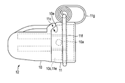
- FIG. 2 is a diagram showing an external configuration of the integrally connected tip cover before mounting, as viewed from the side.
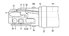
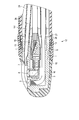
- FIG. 3 is a cross-sectional view showing a cross-sectional configuration of the tip component portion with the tip cover attached as viewed from above.
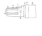
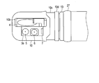
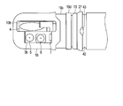
- FIG. 4 is a diagram showing an external configuration of the tip component portion with the tip cover removed as viewed from above.
- FIG. 5 is a diagram showing an external configuration of the tip component portion with the tip cover removed as viewed from the side.
- FIG. 6 is a diagram illustrating an external configuration in which the slide ring of the distal end cover is disposed on the proximal end side of the bending portion.
- FIG. 7 is a diagram illustrating a configuration for removing the second cover from the tip configuration portion.
- FIG. 8 is a diagram illustrating an external configuration of the tip configuration portion with the second cover removed as viewed from above.
- FIG. 9 is a diagram illustrating an external configuration of the distal end configuration portion with the second cover removed as viewed from the side.
- FIG. 10 is a cross-sectional view for explaining leakage of high-frequency current in a distal end configuration portion to which the distal end cover of the insertion device is attached.
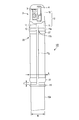
- FIG. 11 is a diagram illustrating a configuration example in which the distal end configuration portion of the insertion device is applied to the distal end configuration portion of the insertion device of the endoscope.
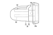
- FIG. 12 is a diagram illustrating an external configuration viewed from the side of the integrally connected tip cover before mounting according to the second embodiment.
- FIG. 13 is a cross-sectional view showing a cross-sectional configuration of the tip component portion with the tip cover attached as viewed from above.
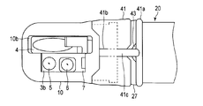
- FIG. 14 is a diagram illustrating an external configuration of a distal end configuration portion to which a distal end cover according to the third embodiment is mounted as viewed from above.
- FIG. 15 is a diagram showing an external configuration of the tip component portion with the second cover removed as viewed from above.
- FIG. 1 is a cross-sectional view showing an external configuration of the insertion device according to the first embodiment viewed from the side
- FIG. 2 is an external view of the integrally connected tip cover before mounting
- FIG. 3 is a cross-sectional view showing a cross-sectional configuration of the front-end component with the front-end cover attached
- FIG. 4 is an external view of the front-end configuration with the front end cover removed.
- FIG. 5 is a diagram showing an external configuration when the distal end component part with the distal end cover removed is viewed from the side, and FIG.
- FIG. 6 is an external configuration in which the slide ring of the distal end cover is arranged on the proximal end side of the bending portion.
- FIG. 11 is a diagram illustrating a configuration example when the distal end configuration portion of the insertion device is applied to the distal end configuration portion of the insertion device of the endoscope.
- the distal end configuration portion of the insertion device including the insertion portion of the endoscope shown in FIG. 11 will be described as an example.
- This tip structure part 2 demonstrates the structural example in which the rocking
- This oscillating table may be an oscillating mechanism that can be changed in the vertical direction or in the horizontal direction intersecting with the vertical direction.
- the treatment instrument is described as a high-frequency treatment instrument, but the present invention is not limited to this.
- the endoscope 100 shown in FIG. 11 includes an insertion device 101 that is inserted into a tube hole or a lumen, and an operation unit 102.
- an insertion port (forceps port) 110 for a treatment tool for performing an electrical treatment for example, a treatment with a high-frequency current, is provided on a site to be treated.
- a columnar tip component 2 is disposed on the distal end side of the insertion device 101, and a swing table operation unit 107 is provided on the operation unit 102.
- the endoscope includes a light source device that supplies illumination light, a control unit that includes a video processor that performs image processing on a captured video signal, a display unit that displays an observation image, It is assumed that a general system configuration is included including a recording unit for recording a video signal.
- the bending portion 103 and the flexible tube 104 are arranged on the proximal end side following the distal end configuration portion 2.
- a long puller wire 9 is internally provided.
- the pulling wire 9 is connected to the swing table operating unit 107.
- the rocking table 4 is swung (turned) by the lever operation of the rocking table operating unit 107 and is raised or inverted.
- the insertion device 101 communicates from the insertion port 110 on the proximal end side and is connected to the treatment instrument channel hole 105 (see FIG. 4), and the channel opening 3a opens at the distal end.
- the high-frequency treatment instrument is inserted from the insertion port 110, passes through the channel line 111, and extends to the outside from the channel opening 3 a of the treatment instrument channel hole 105.
- the tip component part 2 is roughly composed of a base member 3 formed of a metal material such as stainless steel, a swinging base 4 provided rotatably on the base member 3, and a cylindrical tip cover 12. Is done.
- the base member 3 and the outer skin member 26 on the distal end side 20 of the bending portion 103 are fixed by binding of the fixing thin wires 28.
- the outer skin member 26 is a watertight tube made of an insulating resin or rubber.
- a fixing ring portion 27 coated with an insulating resin material is formed so as to cover the surface of the fixing thin wire 28.
- the base member 3 is divided into two along the longitudinal axis direction m. On one side, a channel opening 3a and a rocking base 4 are arranged in front of the channel opening 3a, and on the other side on the outer peripheral surface. On the other hand, a flat observation surface 3b is formed.
- the channel opening 3 a communicates with the insertion port 110 of the insertion device 101 through the treatment instrument channel pipe line 111.
- the illumination window part 5 which irradiates the illumination light light-guided by the optical fiber 16 (refer FIG. 10) is arrange
- a nozzle portion 7 is disposed on the base end side in the longitudinal axis direction, and a cleaning liquid such as physiological saline supplied from an air / water supply pipe 24 or a gas such as air is ejected.
- a cleaning liquid such as physiological saline supplied from an air / water supply pipe 24 or a gas such as air is ejected.
- the illumination window portion 5 and the observation window portion 6 are appropriately cleaned.
- rotation restricting portions 3c and 3d having a groove shape are formed so as to extend parallel to the longitudinal direction.
- the rotation restricting portions 3c and 3d restrict the rotation so that the tip cover 12 attached to the tip constituting portion 2 does not rotate in the circumferential direction.
- cylindrical locking pins 3e fitted in locking holes 10a of the first cover 10 (described later) provided in the distal end cover 12 are provided on both side surfaces at positions proximal to the rotation restricting portions 3c and 3d. Is provided.
- the shape of the locking pin 3e is not limited to a cylindrical shape, and is not particularly limited as long as it is a shape that can be protruded and locked.
- the oscillating base 4 has a concave contact surface that contacts the treatment tool extending from the channel opening 3a and changes the traveling direction, and the connecting portion 21 to which the pulling wire 9 is connected is provided on the outer surface. Is provided.
- the pulling wire 9 is connected to the oscillating table operating unit 107 through a wire guide member 25 fitted to the connecting member 23 fixed by the guide unit 22, and pushes and pulls the connecting unit 21 by lever operation and interlocks with this. Then, the swing table 4 is raised or inverted.
- an insulating ring 13 [electrical insulating portion] having insulating properties is formed over the entire circumference so that the base member 3 is in close contact with the end surfaces of the outer skin member 26 and the fixing thin wire 28.
- the insulating ring 13 is provided on the proximal end side of the flexible tube 104 with respect to the locking pin 3e and the locking hole 10a which are locking portions, that is, the distal end configuration portion 2 and the flexible tube 104 (the distal end of the bending portion). To the outer periphery of the joint part.
- the tip cover 12 of the present embodiment includes a first cover 10 and a second cover 11 having two different actions and functions.
- the first cover 10 is injection-molded into a cylindrical cup shape whose front end side is closed with an elastic-plastic resin material having insulation properties, for example, plastic or the like.
- the second cover 11 is formed in an annular shape by an elastic body having insulating properties or a resin having insulating properties and elasticity.
- the insulation in this embodiment shall have the effect
- the first cover 10 has an opening 10b for exposing the swing table 4, the illumination window part 5 and the observation window part 6 provided in the tip constituting part 2 to be mounted.
- the surface on which the window 10b opens is the upper surface.
- the direction from the distal end side to the proximal end side (opening side) is the longitudinal direction, and the direction orthogonal to the longitudinal direction is the radial direction or the circumferential direction.
- the base end side of the first cover 10 is formed with a joint surface 10c that is one step lower than the outer peripheral surface over the periphery, and has a step at the end on the opening side to increase the thickness and have a locking function.
- a fitted fitting portion 10d is provided. As shown in FIG. 3, the fitting portion 10 d is formed in a tapered shape having an inner surface that expands toward the opening side, so that the fitting portion 10 d can be easily fitted to the tip configuration portion 2.
- circular locking holes (or circular grooves) 10a that fit into the locking pins 3e of the tip component 2 are formed on both side surfaces of the joint surface 10c, thereby contributing to prevention of falling off.
- a plurality of linear slits extending in the longitudinal direction are provided on both side surfaces of the joint surface 10c in order to elastically expand a portion including the locking hole 10a to the outside when the second cover 11 is fitted. 10 g is formed.
- an anti-rotation convex portion 10f composed of two projections
- the second cover 11 is made of an insulating elastic material such as rubber or elastomer.
- the second cover 11 includes a cover main body 11a, an anchor ring 11f (holding portion) having an O-ring shape temporarily fitted to the cover main body 11a, and a long extending arm that is wound and accommodated in the anchor ring 11f. 11g (extension part).
- the cover main body, the anchor ring 11f, and the extending arm 11g are integrally formed of the same material. However, of course, they may be formed of different materials and integrally assembled by welding or the like.
- the base end side contact surface 11c of the cover body 11a is formed so as to coincide with the front end side contact surface 10e of the joint surface 10c of the first cover, and the outer peripheral surface is smoothly connected to the outer peripheral surface of the first cover 10. .
- the inner peripheral surface on the distal end side of the cover main body 11a is formed with a joint surface 11e that comes into close contact with the joint surface 10c when fitted to the first cover 10, and continues to the base end side of the joint surface 11e.
- a fitting groove 11b for fitting with the fitting portion 10d is formed.
- the inner peripheral surface on the proximal end side of the second cover 11 is formed as a joining surface 11 d that fits in close contact with the insulating ring 13 of the distal end component 2.
- the second cover 11 is formed such that when the first cover 10 and the insulating ring 13 are covered, an elastic force toward the center is generated with respect to each part.
- This elastic force can be generated, for example, by reducing the inner diameter of the second cover 11 with respect to the outer diameters of the first cover 10 and the insulating ring 13.
- the bonding surface 10c and the distal end side contact surface 10e and / or the bonding surface 11e and the proximal end side contact surface 11c may be bonded with an adhesive.
- coats an adhesive agent is also a location which mutually contacts, it will not specifically limit.
- the anchor ring 11f of the second cover 11 is fitted to the cover main body 11a in a state in which the extension arm 11g is wound up and stored so as to cross before mounting.
- the anchor ring 11f is slid and positioned in the fitted state from the cover main body 11a to a position beyond the fixed ring portion 31 provided on the bending portion 103 shown in FIG.
- the fixing ring portion 31 has a structure equivalent to the fixing ring portion 27 described above, and is formed so as to cover a fixing thin wire (not shown) that fixes the outer skin member 26 from above.
- the anchor ring 11f When the anchor ring 11f is elastically spread, the anchor ring 11f is larger than the outer diameter A of the fixed ring portion 31 and can pass through the fixed ring portion 31. In a normal state after mounting, the outer diameter A of the fixing ring portion 31 is smaller than the outer diameter A, and the setting is made so as not to return beyond the fixing ring portion 31. That is, the inner diameter of the anchor ring 11f is not more than the outer diameter A of the fixed ring portion 31 and not less than the outer diameter B of the flexible tube, or not more than the outer diameter A and not more than the outer diameter B of the flexible tube.
- the anchor ring 11f that is mounted may have an elastic force that can be slid to the extent that there is no backlash when the bending portion is bent.
- the extending arm 11g connects the cover main body 11a and the anchor ring 11f.
- the extending arm 11g has a belt shape, and is formed in a rectangular shape or a track shape having a flat top and bottom so that the cross-sectional shape can be wound and stored.
- the length of the extending arm 11g is set to a length obtained by adding a movable distance C to the base end side to at least the distance from the position of the mounted distal end cover 12 to the fixing ring portion 31.
- a cut-out portion 11h and two V-grooves or cuts (notches) are formed at the connecting portion of the extension arm 11g with the cover main body 11a so as to cut the cover main body 11a vertically (longitudinal direction) with the width of the extension arm 11g.
- a fragile portion 11j formed by a perforation) or the like is formed.
- the cutout portion 11h is set to a cutout depth at which the insulating ring 13 is not exposed to the outside when the tip cover 12 is attached.
- the fragile portion 11j has a structure in which when the extending arm 11g is pulled up to the distal end side, the fragile portion 11j is separated from the cover main body 11a by being torn from the portion.
- the base end side of the separate first cover 10 is inserted from the front end side of the second cover 11.
- the base end side contact surface 11c and the front end side contact surface 10e are inserted into the second cover 11 from the base end side of the first cover 10, and the joint surface 10c and the joint surface 11e are brought into close contact with each other and fitted.
- the fitting portion 10d is fitted into the mating groove 11b and integrated as the tip cover 12 as shown in FIG.
- the tip cover 12 is put on the tip constituent portion 2, and the joining surface 11 d of the second cover 11 passes over the insulating ring 13 and fits to an appropriate position on the fixing ring portion 27.
- the rotation restricting portions 3 c and 3 d are entered with the anti-rotation convex portion 10 f fitted therein, and the locking pin 3 e of the tip component portion 2 is fitted into the locking hole 10 a.
- the anchor ring 11 f is removed from the second cover 11, moved on the bending portion 103, and attached to a specified position beyond the fixed ring portion 31.
- FIG. 7 is a diagram showing a configuration for removing the second cover 11 from the tip component 2
- FIG. 8 shows an external configuration of the tip component 2 from which the second cover 11 is removed as viewed from above.
- FIGS. 9A and 9B are views showing an external configuration of the distal end configuration portion 2 from which the second cover 11 is removed as viewed from the side.
- the anchor ring 11 f is wound up to the tip side and removed from the first cover 10.
- the extending arm 11 g is pulled up and cut into a strip shape so as to tear the fragile portion 11 j from the cutout portion 11 h of the first cover 11. Further, the second cover 11 is removed from the first cover 10.
- the second cover 11 is removed, and only the first cover 10 is attached to the tip component portion 2.
- the joint surface 10 c including the locking holes 10 a arranged on both side surfaces of the first cover 10 is partially bent upward and removed from the locking pins 3 e of the tip component portion 2.
- the joint surface 10c including the locking hole 10a is easily bent because of the slits 10g formed on both sides, and the bent portion does not return to the original state due to plasticity.
- the 1st cover 10 can be removed by pulling out from the front-end
- a high-frequency treatment instrument is extended from the channel opening 3a (see FIG. 13) of the distal end component 2 through the insertion port 110 shown in FIG.
- the high-frequency current is propagated through the space, and the high-frequency current i also flows in the distal end component 2.
- the second cover 11 and the insulating ring 13 are in close contact with each other, the high frequency current i does not leak from the close contact portion and flow outside the tip cover 12.
- the high-frequency current i does not leak from a portion that cannot be seen by the operator on the back side of the tip cover 12, and even if the tip cover 12 contacts a living tissue other than the treatment target in the body cavity, damage such as burns is caused.
- the possibility can be made very low.
- the first cover 10 and the second cover 11 are produced by separate manufacturing processes and fixed to form the tip cover 12 by fitting, but the present invention is not limited to this.
- the tip cover 12 can be integrally manufactured by a continuous manufacturing process.
- heterogeneous material molding so-called two-color molding can be used in the injection molding manufacturing method.
- this manufacturing method first, a plastic material is injected into the primary side cavity to mold the first cover 10 serving as a primary mold. Continuously, the primary mold is put into the secondary cavity, the rubber material is injected, and the second cover 11 connected to the first cover 10 is integrally formed.
- the tip cover 12 can be manufactured integrally.
- the extension arm 11g and the anchor ring 11f are wound up and fitted to the second cover 11 in a later step.
- the anchor ring 11f at the base end of the extending arm 11g extends to a flexible tube having a thin outer diameter, thereby reducing the outer diameter of the anchor ring 11f. It is possible to prevent the fixed ring portion 31 having a diameter larger than the inner diameter of the anchor ring 11f from slipping out toward the tip side.
- the second cover 11 since the second cover 11 is in close contact with the insulating ring 13 provided on the outer periphery of the proximal end when the second cover 11 is attached to the distal end component 2, the high frequency current exceeds the close contact and the distal cover 12 There is no leakage outside. Further, the boundary portion between the second cover 11 and the first cover 10 is also in close contact, and high-frequency current can be prevented from leaking out of the front end cover 12 from this close contact portion. Accordingly, it is possible to prevent burns or the like other than the treatment target due to leakage of high-frequency current in a region where the surgeon's visual field does not reach.
- the second cover 11 is provided with a fragile portion 11j connected to the extending arm 11g, the second cover 11 can be easily separated from the cover main body 11a by simply pulling the extending arm 11g to the tip side and tearing it from the portion. It can be separated and removed. Further, the first cover 10 remaining in the tip component 2 is partially bent upward at the joint surface 10c including the lock holes 10a disposed on both side surfaces of the first cover 10 to lock the tip component 2. By removing from the pin 3e, it can be easily removed from the tip structure portion 2.
- the insertion device to which the distal end cover of the present embodiment is attached employs the distal end cover that is easy to attach and remove, so that it is prevented from falling into and remaining in the lumen, and in the surgical procedure using high-frequency current.
- the distal end cover of the present embodiment is not limited to an endoscope insertion device (insertion portion), and can be easily applied to distal end configuration portions of various insertion devices.
- FIG. 12 is a diagram illustrating an external configuration of the tip cover 34 according to the second embodiment as viewed from the side.
- FIG. 13 is a cross-sectional view showing a cross-sectional structure of the tip component portion 2 to which the tip cover 34 is attached as viewed from above.
- the tip configuration part 2 of this embodiment is equivalent to the first embodiment described above, and is given the same reference numerals, and the description thereof is omitted.
- the tip cover 34 of the second embodiment will be described.
- the tip cover 34 includes a first cover 10 and a second cover 35 that are equivalent to those of the first embodiment described above.
- the tip cover 34 shown in FIG. 12 has a configuration in which the first cover 10 and the second cover 35 that are separately manufactured are integrally connected, similarly to the configuration shown in FIG.
- the 1st cover 10 is equivalent to the 1st cover 10 of 1st Embodiment, and description here is simplified.
- the second cover 35 is also formed of an insulating elastic material such as rubber or elastomer. Similar to the second cover 11, the second cover 35 is formed with a joint surface and a fitting groove for fitting with the first cover 10 on the distal end side, and the base end side thereof is a rolled-up cylindrical extension.
- the protruding portion 35 a is disposed on the outer peripheral surface of the second cover 35.
- the cylindrical extending portion 35 a is defined such that the extended end is the length from the distal end side of the bending portion 103 to the first pin 103 a of the first joint.
- the cylindrical extending portion 35a is provided with a V-shaped cutout portion equivalent to the weakened portion 11j in the second cover 11, and a weakened portion 35c formed by a cut (perforation) 35b or the like.
- the attachment and detachment of the distal end cover 34 of the present embodiment from the distal end component 2 will be described.
- the first cover 10 is fitted into the second cover 35 and integrated.
- the tip cover 34 is covered from the tip of the base member 3 of the tip constituent portion, and the locking hole 10a is fitted and attached to the locking pin 3e.
- tubular extending portion 35a is extended so as to be unwound, and the insulating ring 13 and the fixing ring portion 27 are exceeded and the outer skin member 26 is attached in close contact with each other. Since the cylindrical extension part 35a of this embodiment is extended so that winding may be released, it becomes the mounting
- the fragile portion 35c of the second cover 35 is lifted up and pulled up to the distal end side, so that the cut 35b is torn up and cut into a strip shape, and then the second cover 35 is removed from the first cover 10. Thereafter, in the same manner as in the first embodiment, the joint surface 10c is partially bent upward to remove the locking hole 10a from the locking pin 3e of the tip component 2, and from the tip component 2 in the longitudinal direction. It can be removed by removing the first cover 10.
- the same effect as that of the first embodiment described above can be obtained.
- the locking portion of the second cover 35 is formed integrally with the cover main body as a cylindrical extension portion 35a
- the cylindrical extension portion 35a is simply formed by covering the tip cover portion and extending it. Mounting can be performed easily.
- it since it extends so that winding may be released from the wound-up state, it is an attachment method which is easy to adhere
- FIG. 14 is a diagram showing an external configuration of the first cover 10 and the second cover 41 according to the third embodiment as viewed from above, and FIG. 15 is a top view of the configuration with the second cover 41 removed from above. It is a figure which shows the external appearance structure seen.
- the tip configuration part 2 of this embodiment is equivalent to the first embodiment described above, and is given the same reference numerals, and the description thereof is omitted.
- the configuration example is a configuration in which the bending portion 103 is mounted at a position beyond the fixing ring portion 31 on the proximal end side.
- the distal end of the bending portion 103 following the distal end configuration portion This is a configuration example to be attached to the fixing ring portion 27 on the side.
- the tip component and the first cover 10 in this embodiment are the same as those in the first embodiment described above, and a description thereof is omitted here.
- the cover body of the second cover 41 is equivalent to the cover body of the second cover 11 of the first embodiment, but the extension arm 41c is shorter than the extension arm 11g, and the anchor ring 41a is shorter.
- This is a configuration that is fitted to the fixing ring portion 27.
- a circular groove 42 is formed on the proximal end side of the fixing ring portion 17.
- the circular groove 42 has such a depth that the fixing thin wire 28 existing below the fixing ring portion 17 is not exposed.
- the anchor ring 41a has a shape that fits into the circular groove 42, and preferably has an elliptical shape. This is arranged so that the minor axis side of the ellipse faces the radial direction of the curved portion 103, thereby suppressing an increase in the outer diameter of the fixing ring portion 17.
- the fixing ring portion 17 is provided with a notch portion 43 for facilitating removal of the anchor ring 41a.
- a notch portion 43 for facilitating removal of the anchor ring 41a.
- it is inserted into the notch 43 and moved to the tip side with the extension arm 41c lifted upward, thereby making the notch 41b. Scrap it into a strip.
- the separated extension arm 41 c is grasped, and the anchor ring 41 a is pulled out from the circular groove 42 and cut to remove the anchor ring 41 a from the first cover 10.
- the 1st cover 10 can be removed similarly to 1st Embodiment.
- the anchor ring 41a is attached to the fixed ring portion 27 on the distal end side of the bending portion 103, the anchor ring 41a can be easily configured without considering the influence of the bending operation in the bending portion 103. Also in the removal, the extension arm 41c can be easily cut off and removed by forming the notch portion 43 in the fixing ring portion 17.
- the present invention can be easily attached to the distal end configuration portion of the insertion device, prevents falling or remaining in the lumen, and prevents leakage of high-frequency current to the outside due to close contact with the distal end configuration portion. It is possible to provide a distal end cover for an endoscope that maintains high safety even in an operation method that uses electric current.
Landscapes
- Physics & Mathematics (AREA)
- Health & Medical Sciences (AREA)
- Life Sciences & Earth Sciences (AREA)
- Optics & Photonics (AREA)
- Surgery (AREA)
- Biomedical Technology (AREA)
- Animal Behavior & Ethology (AREA)
- Radiology & Medical Imaging (AREA)
- Nuclear Medicine, Radiotherapy & Molecular Imaging (AREA)
- Engineering & Computer Science (AREA)
- Biophysics (AREA)
- Heart & Thoracic Surgery (AREA)
- Medical Informatics (AREA)
- Molecular Biology (AREA)
- Pathology (AREA)
- General Health & Medical Sciences (AREA)
- Public Health (AREA)
- Veterinary Medicine (AREA)
- Astronomy & Astrophysics (AREA)
- General Physics & Mathematics (AREA)
- Endoscopes (AREA)
- Instruments For Viewing The Inside Of Hollow Bodies (AREA)
Abstract
Cette invention porte sur un couvercle d'embout pour endoscopes ayant fixé à ce dernier une partie recouverte d'un isolant électrique qui empêche une fuite de courant haute fréquence, ce dernier étant fixé de manière à couvrir une partie constituée d'embout placé dans la pointe d'un dispositif d'insertion d'un endoscope qui est inséré à l'intérieur d'un trou de tube. Ce système peut éviter à la partie recouverte de tomber à l'extérieur ou d'être laissée derrière, comme résultat d'une partie de maintien maintenant le périmètre externe du dispositif d'insertion, ladite partie de maintien étant prévue dans une partie d'extension qui s'étend vers la pointe du dispositif d'insertion.
Applications Claiming Priority (2)
| Application Number | Priority Date | Filing Date | Title |
|---|---|---|---|
| JP2015-135340 | 2015-07-06 | ||
| JP2015135340A JP2018134118A (ja) | 2015-07-06 | 2015-07-06 | 内視鏡の先端カバー |
Publications (1)
| Publication Number | Publication Date |
|---|---|
| WO2017006706A1 true WO2017006706A1 (fr) | 2017-01-12 |
Family
ID=57685494
Family Applications (1)
| Application Number | Title | Priority Date | Filing Date |
|---|---|---|---|
| PCT/JP2016/067415 Ceased WO2017006706A1 (fr) | 2015-07-06 | 2016-06-10 | Couvercle d'embout pour endoscopes |
Country Status (2)
| Country | Link |
|---|---|
| JP (1) | JP2018134118A (fr) |
| WO (1) | WO2017006706A1 (fr) |
Citations (6)
| Publication number | Priority date | Publication date | Assignee | Title |
|---|---|---|---|---|
| JPH07323001A (ja) * | 1994-05-31 | 1995-12-12 | Olympus Optical Co Ltd | 内視鏡 |
| JPH10118014A (ja) * | 1996-10-16 | 1998-05-12 | Olympus Optical Co Ltd | 内視鏡 |
| JPH11501542A (ja) * | 1995-03-07 | 1999-02-09 | エル アデアー エドウィン | 分離型補助アセンブリを備えた滅菌可能な内視鏡 |
| JP2003102668A (ja) * | 2001-09-28 | 2003-04-08 | Fuji Photo Optical Co Ltd | 内視鏡の先端キャップ |
| JP2003230531A (ja) * | 2002-02-07 | 2003-08-19 | Olympus Optical Co Ltd | 内視鏡用フード |
| JP2013172843A (ja) * | 2012-02-24 | 2013-09-05 | Olympus Medical Systems Corp | 内視鏡 |
-
2015
- 2015-07-06 JP JP2015135340A patent/JP2018134118A/ja active Pending
-
2016
- 2016-06-10 WO PCT/JP2016/067415 patent/WO2017006706A1/fr not_active Ceased
Patent Citations (6)
| Publication number | Priority date | Publication date | Assignee | Title |
|---|---|---|---|---|
| JPH07323001A (ja) * | 1994-05-31 | 1995-12-12 | Olympus Optical Co Ltd | 内視鏡 |
| JPH11501542A (ja) * | 1995-03-07 | 1999-02-09 | エル アデアー エドウィン | 分離型補助アセンブリを備えた滅菌可能な内視鏡 |
| JPH10118014A (ja) * | 1996-10-16 | 1998-05-12 | Olympus Optical Co Ltd | 内視鏡 |
| JP2003102668A (ja) * | 2001-09-28 | 2003-04-08 | Fuji Photo Optical Co Ltd | 内視鏡の先端キャップ |
| JP2003230531A (ja) * | 2002-02-07 | 2003-08-19 | Olympus Optical Co Ltd | 内視鏡用フード |
| JP2013172843A (ja) * | 2012-02-24 | 2013-09-05 | Olympus Medical Systems Corp | 内視鏡 |
Also Published As
| Publication number | Publication date |
|---|---|
| JP2018134118A (ja) | 2018-08-30 |
Similar Documents
| Publication | Publication Date | Title |
|---|---|---|
| JP6188993B2 (ja) | 内視鏡のカバー取り外し治具および内視鏡システム | |
| US20210113067A1 (en) | Endoscope cap, endoscope and method of manufacturing endoscope cap | |
| KR101706400B1 (ko) | 내시경용 후드 및 이것을 장착한 내시경 | |
| JP6275337B2 (ja) | 挿入機器及び挿入機器を備える内視鏡 | |
| JPWO2016021234A1 (ja) | 内視鏡の先端構造 | |
| US20070066869A1 (en) | Endoscopic assembly including cap and sheath | |
| WO2003065884A1 (fr) | Capuchon pour endoscope | |
| KR20220047891A (ko) | 마커를 포함하는 전개 카테터 | |
| JP6165386B2 (ja) | 挿入機器の先端カバー及び挿入機器 | |
| JP6250254B1 (ja) | 器具挿入補助具 | |
| JP6165400B1 (ja) | 内視鏡システム、カバー取り外し具 | |
| US20210275354A1 (en) | Lacrimal intubation system | |
| WO2017006706A1 (fr) | Couvercle d'embout pour endoscopes | |
| JP2006055446A (ja) | 内視鏡用鉗子栓 | |
| US20170265722A1 (en) | Assistance tool and endoscope system | |
| US20170035456A1 (en) | Holding mechanism and insertion device | |
| JP2001120496A (ja) | プローブ用湾曲シース | |
| KR101742882B1 (ko) | 성대 미세 내시경 | |
| JP6383606B2 (ja) | 血管剥離デバイス | |
| JPH05161600A (ja) | 内視鏡用処置具 | |
| JP2014000480A (ja) | 補助具及び内視鏡システム | |
| WO2016027490A2 (fr) | Procédé de dissection de vaisseaux |
Legal Events
| Date | Code | Title | Description |
|---|---|---|---|
| 121 | Ep: the epo has been informed by wipo that ep was designated in this application |
Ref document number: 16821176 Country of ref document: EP Kind code of ref document: A1 |
|
| NENP | Non-entry into the national phase |
Ref country code: DE |
|
| 122 | Ep: pct application non-entry in european phase |
Ref document number: 16821176 Country of ref document: EP Kind code of ref document: A1 |
|
| NENP | Non-entry into the national phase |
Ref country code: JP |