WO2017006764A1 - Dispositif de calcul d'image, procédé de calcul d'image, et tomographe - Google Patents
Dispositif de calcul d'image, procédé de calcul d'image, et tomographe Download PDFInfo
- Publication number
- WO2017006764A1 WO2017006764A1 PCT/JP2016/068470 JP2016068470W WO2017006764A1 WO 2017006764 A1 WO2017006764 A1 WO 2017006764A1 JP 2016068470 W JP2016068470 W JP 2016068470W WO 2017006764 A1 WO2017006764 A1 WO 2017006764A1
- Authority
- WO
- WIPO (PCT)
- Prior art keywords
- image
- update
- successive approximation
- vector
- predicted
- Prior art date
- Legal status (The legal status is an assumption and is not a legal conclusion. Google has not performed a legal analysis and makes no representation as to the accuracy of the status listed.)
- Ceased
Links
Images





Classifications
-
- G—PHYSICS
- G06—COMPUTING OR CALCULATING; COUNTING
- G06T—IMAGE DATA PROCESSING OR GENERATION, IN GENERAL
- G06T7/00—Image analysis
- G06T7/0002—Inspection of images, e.g. flaw detection
- G06T7/0012—Biomedical image inspection
-
- A—HUMAN NECESSITIES
- A61—MEDICAL OR VETERINARY SCIENCE; HYGIENE
- A61B—DIAGNOSIS; SURGERY; IDENTIFICATION
- A61B6/00—Apparatus or devices for radiation diagnosis; Apparatus or devices for radiation diagnosis combined with radiation therapy equipment
- A61B6/02—Arrangements for diagnosis sequentially in different planes; Stereoscopic radiation diagnosis
- A61B6/03—Computed tomography [CT]
- A61B6/032—Transmission computed tomography [CT]
-
- A—HUMAN NECESSITIES
- A61—MEDICAL OR VETERINARY SCIENCE; HYGIENE
- A61B—DIAGNOSIS; SURGERY; IDENTIFICATION
- A61B6/00—Apparatus or devices for radiation diagnosis; Apparatus or devices for radiation diagnosis combined with radiation therapy equipment
- A61B6/52—Devices using data or image processing specially adapted for radiation diagnosis
- A61B6/5205—Devices using data or image processing specially adapted for radiation diagnosis involving processing of raw data to produce diagnostic data
-
- A—HUMAN NECESSITIES
- A61—MEDICAL OR VETERINARY SCIENCE; HYGIENE
- A61B—DIAGNOSIS; SURGERY; IDENTIFICATION
- A61B6/00—Apparatus or devices for radiation diagnosis; Apparatus or devices for radiation diagnosis combined with radiation therapy equipment
- A61B6/58—Testing, adjusting or calibrating thereof
- A61B6/582—Calibration
- A61B6/583—Calibration using calibration phantoms
-
- G—PHYSICS
- G01—MEASURING; TESTING
- G01R—MEASURING ELECTRIC VARIABLES; MEASURING MAGNETIC VARIABLES
- G01R33/00—Arrangements or instruments for measuring magnetic variables
- G01R33/20—Arrangements or instruments for measuring magnetic variables involving magnetic resonance
- G01R33/44—Arrangements or instruments for measuring magnetic variables involving magnetic resonance using nuclear magnetic resonance [NMR]
- G01R33/48—NMR imaging systems
- G01R33/4808—Multimodal MR, e.g. MR combined with positron emission tomography [PET], MR combined with ultrasound or MR combined with computed tomography [CT]
- G01R33/4812—MR combined with X-ray or computed tomography [CT]
-
- G—PHYSICS
- G06—COMPUTING OR CALCULATING; COUNTING
- G06T—IMAGE DATA PROCESSING OR GENERATION, IN GENERAL
- G06T12/00—Tomographic reconstruction from projections
- G06T12/20—Inverse problem, i.e. transformations from projection space into object space
-
- G—PHYSICS
- G06—COMPUTING OR CALCULATING; COUNTING
- G06T—IMAGE DATA PROCESSING OR GENERATION, IN GENERAL
- G06T5/00—Image enhancement or restoration
- G06T5/73—Deblurring; Sharpening
-
- A—HUMAN NECESSITIES
- A61—MEDICAL OR VETERINARY SCIENCE; HYGIENE
- A61B—DIAGNOSIS; SURGERY; IDENTIFICATION
- A61B6/00—Apparatus or devices for radiation diagnosis; Apparatus or devices for radiation diagnosis combined with radiation therapy equipment
- A61B6/06—Diaphragms
-
- A—HUMAN NECESSITIES
- A61—MEDICAL OR VETERINARY SCIENCE; HYGIENE
- A61B—DIAGNOSIS; SURGERY; IDENTIFICATION
- A61B6/00—Apparatus or devices for radiation diagnosis; Apparatus or devices for radiation diagnosis combined with radiation therapy equipment
- A61B6/40—Arrangements for generating radiation specially adapted for radiation diagnosis
- A61B6/4035—Arrangements for generating radiation specially adapted for radiation diagnosis the source being combined with a filter or grating
-
- G—PHYSICS
- G01—MEASURING; TESTING
- G01R—MEASURING ELECTRIC VARIABLES; MEASURING MAGNETIC VARIABLES
- G01R33/00—Arrangements or instruments for measuring magnetic variables
- G01R33/20—Arrangements or instruments for measuring magnetic variables involving magnetic resonance
- G01R33/44—Arrangements or instruments for measuring magnetic variables involving magnetic resonance using nuclear magnetic resonance [NMR]
- G01R33/48—NMR imaging systems
- G01R33/54—Signal processing systems, e.g. using pulse sequences ; Generation or control of pulse sequences; Operator console
- G01R33/56—Image enhancement or correction, e.g. subtraction or averaging techniques, e.g. improvement of signal-to-noise ratio and resolution
- G01R33/5608—Data processing and visualization specially adapted for MR, e.g. for feature analysis and pattern recognition on the basis of measured MR data, segmentation of measured MR data, edge contour detection on the basis of measured MR data, for enhancing measured MR data in terms of signal-to-noise ratio by means of noise filtering or apodization, for enhancing measured MR data in terms of resolution by means for deblurring, windowing, zero filling, or generation of gray-scaled images, colour-coded images or images displaying vectors instead of pixels
-
- G—PHYSICS
- G06—COMPUTING OR CALCULATING; COUNTING
- G06T—IMAGE DATA PROCESSING OR GENERATION, IN GENERAL
- G06T2211/00—Image generation
- G06T2211/40—Computed tomography
- G06T2211/424—Iterative
Definitions
- the present invention relates to an image quality improvement technique in an image arithmetic apparatus such as a CT (Computed Tomography) apparatus and a magnetic resonance imaging (hereinafter referred to as MRI) apparatus, and more particularly to an image arithmetic apparatus for providing a high-speed successive approximation method.
- an image arithmetic apparatus such as a CT (Computed Tomography) apparatus and a magnetic resonance imaging (hereinafter referred to as MRI) apparatus
- MRI magnetic resonance imaging
- CT apparatuses and MRI apparatuses are widely used as medical tomographic imaging apparatuses that non-invasively image the human body.
- Research and development of elemental technologies for tomographic imaging devices such as CT and MRI have been conducted with the aim of increasing the accuracy of imaging and expanding the number of cases that can be diagnosed.
- image reconstruction methods such as a CT apparatus and an MRI apparatus are roughly classified into an analytical reconstruction method and an algebraic reconstruction method.
- the analytical reconstruction method is, for example, a Fourier transform method, a filter-corrected back projection method, or a superposition integration method.
- the algebraic reconstruction method is, for example, a successive approximation reconstruction method.
- the image reconstruction algorithm using the conventional iterative approximation method does not converge the objective function (evaluation function) unless it is iterated (updated) many times.For example, the number of times it exceeds tens of times (sometimes hundreds of times). It was necessary to repeat (update). For this reason, there is a problem that it is difficult to generate a reconstructed image in a practical calculation time when the successive approximation method is used in an arithmetic unit of a tomographic imaging apparatus such as a general CT apparatus or an MRI apparatus. .
- An object of the present invention is to generate a reconstructed image with a small number of updates while using a successive approximation method.
- the image processing apparatus of the present invention receives a predetermined tomographic image of a subject and performs an update process by a successive approximation method using the tomographic image as an initial image at least twice to obtain an updated image.
- a prediction update vector is generated by multiplying an update vector corresponding to the difference between the update images of the two successive update processing generated by the first successive approximation processing unit and the first successive approximation processing unit, and using this A prediction update image generation unit that generates a prediction update image, and a process for generating a tomographic image of the subject by repeating the update processing by the successive approximation method using the prediction update image as a new initial image and repeating the process of obtaining the update image And a successive approximation processing unit.
- the number of updates required for convergence of the image reconstruction algorithm using the successive approximation method can be reduced, and a reconstructed image can be generated with less calculation time.
- FIG. 1 is a block diagram showing a configuration of a CT apparatus according to the first embodiment.
- Flowchart showing the operation of the high-speed computing device of the CT apparatus of the first embodiment Flowchart showing the operation of the high-speed computing device of the CT apparatus of the first embodiment
- an image (image vector) obtained by a second successive approximation process from an image (image vector) obtained using the predicted update vector a predicted update vector is obtained by multiplying the update vector by a coefficient
- FIG. 1 shows an external view of a CT apparatus according to the present embodiment
- FIG. 2 shows an overall configuration of the CT apparatus.
- the CT device is composed of a scanner 101 used for imaging, a bed 102 for moving a subject, a mouse, a keyboard, etc., for measuring and reconfiguring bed movement speed information and reconstruction position.
- An input device 103 that receives input of parameters to be used from an operator, an arithmetic device 104 that processes measurement data output from the scanner 101, and a display device 105 that displays a reconstructed image are provided.
- the scanner 101 includes an X-ray generator 111, a high voltage generator 112, an X-ray controller 113, a data acquisition system 129, a scanner controller 115, and a central controller 126.
- the high voltage generator 112 generates a predetermined current and high voltage under the control of the X-ray controller 113 and supplies the generated current and high voltage to the X-ray generator 111.
- the X-ray generator 111 generates X-rays.
- the X-ray generator 111 and the detector 121 are mounted on a disk 114 having an opening for inserting a subject 117 at the center.
- the disk 114 is provided with a drive device 116 that rotationally drives the disk 114.
- the disk 114 is also mounted with a bow-tie filter 118 and a collimator 119 at a position where X-rays generated by the X-ray generator 111 are transmitted.
- a collimator control device 120 is connected to the collimator 119.
- the scanner control device 115 is connected to the drive device 116 and the collimator control device 120, and controls the rotation and stop of the disk 114 and the opening of the collimator 119.
- a preamplifier 122 and an A / D converter 123 are connected to the detector 121 in this order.
- the preamplifier 122 amplifies the output of the detector 121, and the A / D converter 123 converts it into a digital signal and passes it to the arithmetic unit 104.
- a preamplifier 122 and an A / D converter 123 are also mounted on the disk 114.
- the detector 121, the preamplifier, and the A / D converter 123 constitute a data collection system 129.
- the bed 102 has a built-in bed driving unit that moves the bed 102 with respect to the disk 114.
- the couch drive unit is connected to a couch controller 124 that controls the amount of driving thereof and a couch movement measuring device 125.
- the display device 105 and the input device 103 constitute an input / output device 107.
- a storage device 108 is also arranged in the input / output device 107.
- the arithmetic device 104 includes a correction processing device 131, a reconstruction arithmetic device 132, an image processing device 133, and a high-speed arithmetic device 134.
- the input / output device 107 and the arithmetic device 104 constitute an operation unit 106.
- the operator uses the input device 103 in the operation unit 106 to obtain imaging conditions (bed movement speed, tube current, tube voltage, slice position, etc.) and reconstruction parameters (region of interest, reconstruction image size, backprojection phase width, reconstruction filter). Function, image thickness in the body axis direction, etc.), based on the instruction, the central controller 126 sends control signals necessary for imaging to the X-ray controller 113, the bed controller 124, and the scanner controller 115. Output to.
- imaging conditions bed movement speed, tube current, tube voltage, slice position, etc.
- reconstruction parameters region of interest, reconstruction image size, backprojection phase width, reconstruction filter. Function, image thickness in the body axis direction, etc.
- a control signal is sent from the X-ray controller 113 to the high voltage generator 112, a high voltage is applied to the X-ray generator 111, and the subject 117 is irradiated with X-rays from the X-ray generator 111 Is done.
- a control signal is sent from the scanner control device 115 to the drive device 116 to rotate the disk 114.
- the X-ray generator 111, the detector 121, the preamplifier 122, etc. circulate around the subject.
- the bed control device 124 under the control of the bed control device 124, the bed 102 on which the subject 117 is placed moves in parallel in the body axis direction or stops.
- the X-rays irradiated from the X-ray generator 111 are shaped by the Bow-tie filter 118, and then the irradiation region is limited by the collimator 119, and the subject 117 is irradiated.
- X-rays are absorbed (attenuated) by each tissue in the subject 117, pass through the subject 117, and are detected by the detector 121 at a sampling interval determined in the rotation direction.
- This data collection unit in the rotation direction is called a view.
- the detector 121 has a configuration in which detection elements are arranged two-dimensionally. The arrangement of elements in the rotation direction is called a channel, and the direction orthogonal to the row is called a column, and the data to be collected is identified by the view, channel, and column. .
- X-rays detected by each detection element of the detector 121 are converted into a current, amplified by a preamplifier 122, converted into a digital signal by an A / D converter 123, and output to the arithmetic unit 104.
- the correction processing device 131 of the arithmetic device 104 is configured to perform offset correction processing, air correction processing, reference correction processing, logarithmic conversion processing, beam correction on the digital signal from the A / D converter 123 to correct an output offset due to dark current of the detection element Performs phantom correction processing to suppress the hardening effect.
- the corrected data is stored in the storage device 108 in the input / output device 107 as measured projection data.
- the reconstruction calculation device 132 performs image reconstruction processing on the actually measured projection data.
- the reconstruction calculation device 132 performs image reconstruction processing based on an analytical reconstruction method (for example, a Fourier transform method, a filtered back projection method, a superposition integration method, or the like) that generally completes a calculation in a short time.
- the reconstructed image is stored in the storage device 108 in the input / output device 107 and displayed on the display device 105 as a CT image. Further, when the operator instructs the displayed CT image to change the display cross section through the input device 103, the image processing device 133 executes the instructed processing.
- the high-speed computing device 134 further processes the reconstructed image generated by the reconstruction computing device 132 based on the analytical reconstruction method by a successive approximation method that is an algebraic reconstruction method, and generates a highly accurate image.
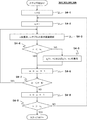
- the high-speed computing device 134 has a CPU (Central Processing Unit) and a memory (both not shown), and the CPU reads and executes a program stored in advance in the memory, thereby performing FIG. 3 and FIG. It operates like the flow of 4 and generates an image by the successive approximation method.
- a configuration using a GPU (Graphics Processing Unit) chip instead of a CPU, or an integrated circuit (hardware) such as an FPGA (Field-Programmable Gate Array) or an ASIC (Application Specific Integrated Circuit) performs the calculation of the successive approximation method. It may be a configuration.
- an update expression used for the update (iteration) calculation uses a data fidelity term and a regularization term.
- the data fidelity term is a term for evaluating the similarity between the actual projection data collected by the data collection system 129 and the forward projection data obtained by forward projecting the reconstructed image.
- the regularization term is a term that evaluates the reconstructed image based on prior knowledge about the generated image, and acts here to force the image to be a flat image with little spatial variation in pixel values. .
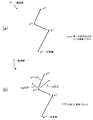
- the high-speed arithmetic unit 134 corresponds to the difference vector between the two obtained images x (N) and x (N ⁇ 1) (for example, x (3) and x (2) ) after the update.
- a prediction update vector obtained by multiplying the update vector x ⁇ (N ⁇ 1, N) by a predetermined coefficient is generated, and a prediction update image is generated using the prediction update vector.
- x ⁇ (N) is generated (see steps 307 to 309, FIG. 5 (b) and FIG. 6 (a)).
- a predicted updated image x ⁇ (N) approximated to an image after performing a plurality of update calculations can be obtained by a single calculation.
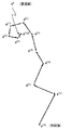
- the high-speed computing device 134 uses the calculated predicted update image x ⁇ (N) as an initial image, performs an image update (repetition) operation by the successive approximation method a predetermined number of times, and updates the image x (P) ( A tomographic image of the subject is obtained. (Steps 310 to 315, FIG. 6 (b)). This is called a second successive approximation process.
- the updated image x (N) is displayed (step 316).
- the update vector is multiplied by the coupling coefficient to obtain a predicted update vector, and a predicted update image is obtained by using this to calculate a plurality of update calculations.
- a predicted update image is obtained by using this to calculate a plurality of update calculations.
- the optimal solution x * can be converged (or asymptotically) with a smaller number of update computations as shown in FIG. 6B. Therefore, it is possible to generate a highly accurate image using the successive approximation method at high speed.
- FIGS. 3 and 4 The flow of FIGS. 3 and 4 will be described in detail below.
- step 301 the high speed computing device 134 reads the reconstructed image generated by the reconstruction computing device 132 from the storage device 108 and sets it as the initial image x (0) . Then, a predetermined update formula is applied to the initial image x (0 ) to generate an updated image x (1) (steps 302 and 303).
- a formula including both a data fidelity term and a regularization term is used. More specifically, an update formula that satisfies the following conditions (A) and (B) is used here.
- x (n) is an image after n times of update
- x (n ⁇ 1) is an update image of the (n ⁇ 1) th time.
- x (n) is also referred to as an image vector.
- the starting point of the image vector is a point where the values of all the pixels are 0 (FIGS. 5, 6, and 7).
- ⁇ (x) is the first derivative of the evaluation function ⁇ (x).
- ⁇ n is a relaxation coefficient that adjusts the degree of update, and is set in advance for each update number n.
- D is a Hessian matrix of the evaluation function ⁇ (x), but a Lipschitz constant of ⁇ (x) can also be used.
- D using the Lipschitz constant of ⁇ (x) for example, those described in Non-Patent Document 2 can be used.
- the evaluation function ⁇ (x) is expressed as the equation (2) by the sum of the data fidelity term g (x) and the regularization term f (x).
- the data fidelity term g (x) constrains the state of the image from the measured projection data, that is, the similarity between the measured projection data collected by the data collection system 129 and the forward projected data obtained by forward projecting the reconstructed image. Equation (3) is used to evaluate The regularization term f (x) uses Equation (4) that evaluates smoothness between adjacent pixels.
- the data fidelity term g (x) and the regularization term f (x) are closer to the optimal image x as the value is smaller, and the evaluation is higher (that is, the value of the evaluation function ⁇ (x) is smaller).
- Equation (3) y is a vector of measured projection data collected by the data collection system 129.
- A is a conversion matrix from an image to projection data.
- W is a matrix having a weighting coefficient obtained by quantifying the statistical fluctuation of the actually measured projection data y as a diagonal component.
- k is an index that represents the direction of the adjacent pixel viewed from the target pixel of the image x
- K is the total number of directions. For example, in the case of targeting 26 pixels adjacent in a three-dimensional image, K is 13 if overlap is avoided.
- ⁇ k is an arbitrary parameter that determines the regularization strength in the k direction
- C k is a matrix for extracting adjacent elements of the image vector.
- J ⁇ 1,..., J ⁇ is a pixel index.
- ⁇ jk is a weighting factor between the pixels j and k, and is determined by the reciprocal of the distance between the pixels as an example.
- ⁇ is a potential function, and a continuous function that can be differentiated everywhere such as Huber function and Fair function is used.
- the data fidelity term g (x) and the regularization term f (x) are expressed by the above equations (3) and (4), but in the present embodiment, the equations (3) and (4)
- the function is not limited, and any desired function can be used as long as the first derivatives ⁇ g (x) and ⁇ f (x) can be calculated.
- the update formula is not limited to the formula (1), and a desired formula can be used.
- the updated image x (1) is generated once from the image x (0) in step 303, the updated image x (1) is stored in the storage device.
- the update operation in steps 303 and 304 is repeated until the number of updates reaches a predetermined number N (steps 305 and 306).
- the updated images x (1) to x (N) (for example, x (1) , x (2) , x (3) ) are stored in the storage device 108.
- the first successive approximation process (steps 301 to 305) is completed.
- the predetermined number N of update times is set to 3, but the number is not limited to this number, and can be set to a predetermined number.
- the number of times that the evaluation function ⁇ (x) or the rate of change ⁇ ⁇ ⁇ (x) of the evaluation function often reaches a predetermined value or less can be obtained in advance, and the number can be set as N.
- SD (Standard Deviation) reduction rate known as one of the quantitative values of the noise reduction effect of the successive approximation method is calculated, and the number of times that the SD reduction rate often reaches a predetermined value or less is obtained in advance.
- the number of times can be set as N.
- the SD reduction rate is the reconstructed image generated by the above-described analytical reconstruction method (in this embodiment, the initial image x (0 based on the SD value) is equal to), the fraction of SD value is reduced images generated by the method of successive approximation, represented by the formula (5).
- the SD reduction rate calculated by the equation (5) is a reduction rate of the SD value of the generated image of the first successive approximation method based on the SD value of the initial image x (0) .
- step 307 the image at the time when the successive approximation method converges (or asymptotically) with reference to the initial image x (0) read in step 301 is used.
- Predict SD reduction rate Since ⁇ k in equation (4) is an arbitrary parameter that determines the smoothing strength of the successive approximation method, the reconstruction parameter (initial image x (0) and the reconstructed image size of the successive approximation method, Projection phase width, reconstruction filter function, image thickness in the body axis direction) and values and distribution of measured projection data that change according to the voltage and current applied to the subject and the X-ray generator.
- the predicted value of the SD reduction rate with respect to the smoothing strength of the successive approximation method can be calculated by tabulating the relationship between the conditions for setting the reduction rate.
- the predicted value of the SD reduction rate is calculated for each pixel by the following equation (6).
- Equation (6) F is a table prepared in advance for each condition for setting the reduction rate.
- the conditions for setting the reduction rate such as the above reconstruction parameters (initial image x (0) and reconstructed image size, backprojection phase width, reconstruction filter function, image thickness in the body axis direction of the successive approximation method) are set. Fixed, plots the SD reduction rate while changing the parameter ⁇ k , and fits the function by the least squares method.
- the function is derived under each condition while changing the conditions for setting the reduction rate, for example, the applied voltage is changed to 80 kV, 100 kV, 120 kV, and 140 kV.
- the function is calculated for several phantoms with different diameters using the measured projection data obtained by imaging a cylindrical water phantom instead of the subject. Keep it.
- the function of the phantom having the closest area is adopted as the table F according to the area of the measured projection data of the subject.
- SD reduction rate prediction method in step 307 is not limited to the above example, and any known method can be applied.
- h g (b) and h f (b) are functions that are uniquely determined for the variable b, and approximate the following formula (14) for measured projection data for clinical data or image quality quantification phantoms, etc.
- Functions h g (b) and h f (b) that minimize the error are calculated in advance by the least square method or the like.
- the coupling coefficients a g and a f corresponding to the predicted value of the SD reduction rate calculated in step 307 are calculated or read out for each pixel.
- the vector component derived from the data fidelity term is x g (N-1, N)
- the vector component derived from the regularization term is x f
- (N ⁇ 1, N) these are represented by the above formula (1), which is an update formula, and the following formula (9) to formulas (10) and (11).
- the high-speed computing device 134 calculates the vector component x g (N ⁇ 1, N) derived from the data fidelity term and the vector component x f derived from the regularization term among the update vectors from the equations (10) and (11).
- the predicted update image x ⁇ (N) x ⁇ (n 1 , n 2 ) is the sum of two types of update vectors (predicted update vectors) multiplied by the coupling coefficient and the reconstructed image after being updated by n 1 iterations. It is.
- T in a g T and a f T represents transposition of a vector.
- the high-speed computing device 134 reads the calculated predicted update image x ⁇ (N) from the storage device 108 as an initial image (step 310), and uses the predetermined update formula to update the updated image x (n + 1) .
- Generate Steps 311 and 3112.
- the update formula the above-described formula (1) can be used, and of course, a formula different from the formula (1) can be used.
- the generated image x (n + 1) is stored in the storage device 108 (step 313). This is repeated until the total number of updates reaches a predetermined number P (steps 314 and 315).
- the updated image x (P) is stored in the storage device 108 and displayed on the display device 105 (step 316).
- each side of equation (16) is minimized. Since the calculation of each side of Equation (16) is completed using 1 / M measured projection data, when all data is used for updating, it is updated M times compared to Equation (1). The frequency is obtained.
- the update formula in the n-th iteration and the m-th subset can be expressed by the following formula (17).
- x (n, m) is a provisional image vector in the nth iteration and the mth subset
- x (n, M) is equivalent to x (n + 1,0)
- step 301 in FIG. 3 the high-speed computing device 134 reads the reconstructed image generated by the reconstruction computing device 132 as the initial image x (0) .
- Steps 302, 303, 305, and 306 in FIG. 3 are executed as in the flow in FIG.
- the predicted updated image x ⁇ (N) is set as an initial image (step 310 in FIG. 4), and the second successive approximation process is performed. Specifically, steps 311 to 315 in FIG. 4 are performed by steps S5-1 to S5-7 in FIG.
- steps S5-1 and S5-2 an index n of iteration and an index m of subset are initialized.
- step S5-3 the image is updated according to the update formula (17). This is repeated until the subset index m reaches M (steps S5-4 and S5-5).
- step S5-5 If the subset index m reaches M in a round in step S5-5, the iterative index n is updated in step S5-6, and further the image is updated.
- Non-Patent Document 3 satisfies the above-mentioned conditions (A) and (B), and can update the update vector of the data fidelity term and the regularization term in the step of updating the image, respectively. Therefore, a predicted update image can be generated as in the present embodiment.
- Embodiment 2 ⁇ Embodiment 2 >> Embodiment 2 will be described.
- the vector component x g () of the data fidelity term of the difference vector (update vector) of the update image is performed.
- N-1, N) and the vector component x f (N-1, N) derived from the regularization term calculate the prediction update vector obtained by multiplying these by the coupling coefficient, and use this to calculate the prediction update image Ask for.
- Embodiment 2 uses an update expression that satisfies the following conditions (A) and (C) as an update expression for the first successive approximation process.
- (A) Includes data fidelity term and regularization term in evaluation function (C)
- the data fidelity term and regularization term in (A) are updated alternately (i.e., the regularization term is updated with the data fidelity term as a constant, and then the data fidelity with the regularization term as a constant).
- Update the section Specifically, the update formula described in Non-Patent Document 4 is used as the update formula that satisfies the conditions (A) and (C).
- Non-Patent Document 4 The update formula described in Non-Patent Document 4 will be described.
- the update formula of this embodiment is optimal after introducing a new variable in the data fidelity term and formulating the relational expression of the introduced variable as a constraint condition when optimizing the formulas (2) to (4) described above. To do.
- Equations (26.1), (26.2), and (26.3) are a series of update procedures in the nth iteration and the mth subset, but depending on the nature of the regularization term f (x), x in Equation (26.2) (n, m) may be calculated iteratively. Therefore, Equation (26.2) solves the partial problem of iteratively calculating x (n, m) using the well-known Fast Iterative Shrinkage Thresholding Algorithm (FISTA, Non-Patent Document 2).
- FISTA Fast Iterative Shrinkage Thresholding Algorithm
- the update vector ⁇ f (n, m) can be accumulated in the iterative process of Equation (27).
- the update index of the partial problem in Equation (27) is set as ⁇ , and the provisional image is set as z ( ⁇ ) .
- ⁇ f (n, m ) Is expressed by the following equation (31).
- the vector components x g (n 1 , n 2 ) and x f (n 1 , n 2 ) of the update vector can be calculated by substituting for ⁇ f (n, m) in (19).
- Embodiment 3 A third embodiment will be described.
- the third embodiment uses an update formula that satisfies the above conditions (A) and (C) and introduces a new variable into the regularization term.
- a continuous function that satisfies the conditions (A) and (C) and that cannot be differentiated is used as a regularization term.
- Continuous functions that cannot be differentiated are represented by Total Variation (TV), and are expressed by the following equations (32) to (35).
- Equations (33) and (34) are called anisotropic TV and isotropic TV, respectively, and are selected and adopted according to the application.
- equation (38) the following equations (41.1) to (41.3) are obtained by alternately minimizing the three variable vectors.
- Equation (43) The shrink function of Equation (41.2) and Equation (41.2) is expressed by the following Equation (43).
- Embodiments 1 and 2 The concept of this embodiment is the same as in Embodiments 1 and 2, and an update vector derived from a data fidelity term and an update vector derived from a regularization term are calculated.
- the right side of the equation (41.1) is partially differentiated with respect to x to obtain the following equation.
- Equation (44) is substituted into ⁇ g (n, m) in Equation (17), and Equation (47) is substituted into ⁇ f (n, m) in Equation (19), Vector components x g (n 1 , n 2 ) and x f (n 1 , n 2 ) of the update vector can be calculated.
- the prediction vector derived from each term is easily separated by paying attention to the update component of each term in the update formula. be able to.
- Non-Patent Document 6 describes a method for applying the Alternative Direction Method of Multipliers (ADMM) algorithm and a method for applying the Split Bregman method after changing and separating regularization terms as well as data fidelity terms. Yes.
- Non-Patent Document 7 describes an algorithm for separating variables between a data fidelity term and a regularization term. An update formula based on these can also be used.
- ADMM Alternative Direction Method of Multipliers
- Embodiment 4 >> Embodiment 4 will be described.
- a predetermined N iterations are performed, and the second successive approximation process (steps 311 to 306) is performed.
- 315) is a configuration in which a predetermined (PN) iteration process is performed.
- PN predetermined
- the high-speed computing device 134 can be configured to receive the value of the total number P of the iterative processes of the first and second successive approximation processes from the operator.
- the number of iterations N and (P ⁇ N) of the first successive approximation process and the second successive approximation process are generally higher when the former is large and the latter is small. Since the number of iterations of the approximation process is too small, it may not be asymptotic enough to the optimal solution.
- the speed-up effect according to the present invention may be insufficient.
- the obtained relationship between P and N can be stored in the storage device 108 as a table or a function.
- the high-speed computing device 134 can read or calculate the value of N corresponding to P set by the operator from the table.
- Embodiment 5 ⁇ Embodiment 5 >> Embodiment 5 will be described.
- step 501 the high-speed computing device 134 calculates the SD reduction rate or the evaluation function ⁇ using the predetermined formula for the updated image x (n + 1) generated in step 304 and stores it in the storage device 108.
- the amount of change is the index E
- the difference from the previously stored SD reduction rate or the value of the evaluation function ⁇ is further calculated.
- the predetermined formula for example, formulas (49) and (50) can be used.
- step 502 the index E calculated in step 501 is compared with a predetermined value. If the index E is smaller than the predetermined value, the updated image x (n + 1) is updated to the predicted updated image X. It is determined that the solution is close to the optimum solution to the extent suitable for generating ⁇ (N) , the iteration of the first successive approximation process is terminated, and the process proceeds to step 307.
- the high-speed arithmetic device 134 can finish the first successive approximation process before the number n of the iterative processes reaches N, and can generate the predicted update image x ⁇ (N) in steps 307 to 309. .
- step 502 determines whether the index E is smaller than the predetermined value in step 502 or not smaller than the predetermined value in step 502. If the index E is not smaller than the predetermined value in step 502, the process proceeds to step 305, and if the number n of the iterative process does not exceed N, the iterative process is continued. If the number n of iterations exceeds N before the index E becomes smaller than a predetermined value, the process proceeds to step 307 and the iterations are terminated. Therefore, the upper limit of the number of iterations n can be maintained at N times.
- the first iterative approximation process since it is possible to determine whether or not to continue the iterative process from the state of the image after the update, the first iterative approximation process does not perform an iterative process more than necessary and can be performed at a higher speed.
- a prediction update image can be generated.
- step 311 to 315) of FIG. 4 the number of iterations is a predetermined number P.
- steps 511 and 512 for calculating the index E may be inserted to determine whether or not the updated image x (n + 1) is approaching the optimal solution. Is possible.
- Other steps in the flow of FIG. 11 are the same as those in FIG.
- step 511 any index E is calculated for the updated image x (n + 1) generated in step 312 as in step 501.
- step 512 the index E calculated in step 501 is compared with a predetermined value. If the index E is smaller than the predetermined value, it is determined that the solution is sufficiently close to the optimal solution, and the second The iteration of the successive approximation process is terminated, and the process proceeds to step 316.
- the predetermined value for determining the index E in step 512 can be a value different from the predetermined value in step 502.
- the high-speed computing device 134 can end the first successive approximation process before the number n of the iterative processes reaches P.
- step 502 determines whether the index E is smaller than a predetermined value. If it is determined in step 502 that the index E is not smaller than a predetermined value, the process proceeds to step 314, and if the number n of the iterative process does not exceed P, the iterative process is continued. If the number of iterations n exceeds P before the index E determined in step 511 becomes smaller than a predetermined value, the process proceeds to step 316 and the iteration is terminated. Therefore, the upper limit of the total number of iterations n of the first and second successive approximation processes can be maintained at P times.
- the second successive approximation process since it is possible to determine whether or not to continue the iterative process from the state of the image after the update, the second successive approximation process does not perform an iterative process more than necessary, An image asymptotic to the optimal solution can be generated at a higher speed.
- the CT apparatus has been described.
- the processing of the high-speed arithmetic device 134 of the present embodiment can be used for image generation of other image capturing apparatuses such as an MRI apparatus.
- Embodiments 1 to 3 the case where the evaluation function is composed of two data fidelity terms and a regularization term has been described. However, for an evaluation function composed of three or more terms, three or more predicted update vectors are used. You may make it respond
Landscapes
- Engineering & Computer Science (AREA)
- Health & Medical Sciences (AREA)
- Life Sciences & Earth Sciences (AREA)
- Physics & Mathematics (AREA)
- Medical Informatics (AREA)
- Nuclear Medicine, Radiotherapy & Molecular Imaging (AREA)
- Theoretical Computer Science (AREA)
- General Health & Medical Sciences (AREA)
- Radiology & Medical Imaging (AREA)
- Pathology (AREA)
- High Energy & Nuclear Physics (AREA)
- Biomedical Technology (AREA)
- Public Health (AREA)
- Biophysics (AREA)
- Veterinary Medicine (AREA)
- Heart & Thoracic Surgery (AREA)
- Molecular Biology (AREA)
- Surgery (AREA)
- Animal Behavior & Ethology (AREA)
- Optics & Photonics (AREA)
- General Physics & Mathematics (AREA)
- Pulmonology (AREA)
- Computer Vision & Pattern Recognition (AREA)
- Condensed Matter Physics & Semiconductors (AREA)
- Quality & Reliability (AREA)
- Apparatus For Radiation Diagnosis (AREA)
- Algebra (AREA)
- Mathematical Analysis (AREA)
- Mathematical Optimization (AREA)
- Mathematical Physics (AREA)
- Pure & Applied Mathematics (AREA)
Abstract
Priority Applications (3)
| Application Number | Priority Date | Filing Date | Title |
|---|---|---|---|
| CN201680026040.0A CN107530043B (zh) | 2015-07-08 | 2016-06-22 | 图像运算装置、图像运算方法及断层图像拍摄装置 |
| JP2017527167A JP6454011B2 (ja) | 2015-07-08 | 2016-06-22 | 画像演算装置、画像演算方法、および、断層画像撮影装置 |
| US15/580,337 US10410343B2 (en) | 2015-07-08 | 2016-06-22 | Image computing device, image computing method, and tomograph |
Applications Claiming Priority (2)
| Application Number | Priority Date | Filing Date | Title |
|---|---|---|---|
| JP2015-137260 | 2015-07-08 | ||
| JP2015137260 | 2015-07-08 |
Publications (1)
| Publication Number | Publication Date |
|---|---|
| WO2017006764A1 true WO2017006764A1 (fr) | 2017-01-12 |
Family
ID=57685572
Family Applications (1)
| Application Number | Title | Priority Date | Filing Date |
|---|---|---|---|
| PCT/JP2016/068470 Ceased WO2017006764A1 (fr) | 2015-07-08 | 2016-06-22 | Dispositif de calcul d'image, procédé de calcul d'image, et tomographe |
Country Status (4)
| Country | Link |
|---|---|
| US (1) | US10410343B2 (fr) |
| JP (1) | JP6454011B2 (fr) |
| CN (1) | CN107530043B (fr) |
| WO (1) | WO2017006764A1 (fr) |
Cited By (3)
| Publication number | Priority date | Publication date | Assignee | Title |
|---|---|---|---|---|
| JP2020521134A (ja) * | 2017-05-22 | 2020-07-16 | プリズマティック、センサーズ、アクチボラグPrismatic Sensors Ab | 画像再構築のための方法および装置 |
| JP2020521961A (ja) * | 2017-06-02 | 2020-07-27 | コーニンクレッカ フィリップス エヌ ヴェKoninklijke Philips N.V. | エミッショントモグラフィで反復再構成された画像の定量的な保証の尺度として信頼値を提供するシステム及び方法 |
| CN112215779A (zh) * | 2020-10-28 | 2021-01-12 | 青岛大学 | 一种图像处理方法、装置、设备及计算机可读存储介质 |
Families Citing this family (2)
| Publication number | Priority date | Publication date | Assignee | Title |
|---|---|---|---|---|
| JP7114347B2 (ja) * | 2018-06-04 | 2022-08-08 | 浜松ホトニクス株式会社 | 断層画像予測装置および断層画像予測方法 |
| CN114726966A (zh) * | 2022-03-09 | 2022-07-08 | 太原陆装机电科技有限公司 | 基于各向异性全变分的电磁信号降噪方法 |
Citations (3)
| Publication number | Priority date | Publication date | Assignee | Title |
|---|---|---|---|---|
| WO2012050149A1 (fr) * | 2010-10-14 | 2012-04-19 | 株式会社 日立メディコ | Appareil ct à rayons x et procédé de reconstruction d'images |
| WO2014084291A1 (fr) * | 2012-11-30 | 2014-06-05 | 株式会社 日立メディコ | Dispositif ct à rayons x et procédé d'imagerie tomographique associé |
| JP2015080719A (ja) * | 2013-10-24 | 2015-04-27 | 株式会社東芝 | X線コンピュータ断層撮影装置、医用画像処理装置および医用画像処理方法 |
Family Cites Families (14)
| Publication number | Priority date | Publication date | Assignee | Title |
|---|---|---|---|---|
| WO2007095312A2 (fr) * | 2006-02-13 | 2007-08-23 | University Of Chicago | Reconstruction d'image à partir de données incomplètes ou en nombre limité |
| US7831097B2 (en) | 2006-03-16 | 2010-11-09 | Siemens Medical Solutions Usa, Inc. | System and method for image reconstruction |
| US8472688B2 (en) * | 2008-04-17 | 2013-06-25 | Wisconsin Alumni Research Foundation | Method for image reconstruction employing sparsity-constrained iterative correction |
| US8620054B2 (en) * | 2010-09-08 | 2013-12-31 | SOCPRA—Sciences Sante et Humaines, s.e.c. | Image reconstruction based on accelerated method using polar symmetries |
| CN103260520B (zh) * | 2010-12-10 | 2015-06-17 | 株式会社日立医疗器械 | X射线ct装置以及图像重构方法 |
| US20130336562A1 (en) * | 2012-06-15 | 2013-12-19 | Toshiba Medical Systems Corporation | Adaptively determined parameter values in iterative reconstruction method and system |
| WO2014030543A1 (fr) * | 2012-08-22 | 2014-02-27 | 株式会社 日立メディコ | Appareil de tomodensitométrie par rayons x et procédé de génération d'image de tomodensitométrie par rayons x |
| CN103971349B (zh) * | 2013-01-30 | 2017-08-08 | 上海西门子医疗器械有限公司 | 计算机断层扫描图像重建方法和计算机断层扫描设备 |
| WO2014172421A1 (fr) * | 2013-04-16 | 2014-10-23 | The Research Foundation | Reconstruction itérative pour une tomodensitométrie utilisant une régularisation non locale provoquée par une image antérieure |
| US9261467B2 (en) * | 2013-06-14 | 2016-02-16 | General Electric Company | System and method of iterative image reconstruction for computed tomography |
| US9208588B2 (en) * | 2013-09-25 | 2015-12-08 | Wisconsin Alumni Research Foundation | Fast statistical imaging reconstruction via denoised ordered-subset statistically-penalized algebraic reconstruction technique |
| KR20160010221A (ko) * | 2014-07-18 | 2016-01-27 | 삼성전자주식회사 | 의료 영상 촬영 장치 및 그에 따른 영상 처리 방법 |
| CN105488823B (zh) * | 2014-09-16 | 2019-10-18 | 株式会社日立制作所 | Ct图像重建方法、ct图像重建装置及ct系统 |
| US10643354B2 (en) * | 2015-03-20 | 2020-05-05 | Rensselaer Polytechnic Institute | Automatic system calibration method of X-ray CT |
-
2016
- 2016-06-22 CN CN201680026040.0A patent/CN107530043B/zh active Active
- 2016-06-22 WO PCT/JP2016/068470 patent/WO2017006764A1/fr not_active Ceased
- 2016-06-22 JP JP2017527167A patent/JP6454011B2/ja active Active
- 2016-06-22 US US15/580,337 patent/US10410343B2/en active Active
Patent Citations (3)
| Publication number | Priority date | Publication date | Assignee | Title |
|---|---|---|---|---|
| WO2012050149A1 (fr) * | 2010-10-14 | 2012-04-19 | 株式会社 日立メディコ | Appareil ct à rayons x et procédé de reconstruction d'images |
| WO2014084291A1 (fr) * | 2012-11-30 | 2014-06-05 | 株式会社 日立メディコ | Dispositif ct à rayons x et procédé d'imagerie tomographique associé |
| JP2015080719A (ja) * | 2013-10-24 | 2015-04-27 | 株式会社東芝 | X線コンピュータ断層撮影装置、医用画像処理装置および医用画像処理方法 |
Cited By (5)
| Publication number | Priority date | Publication date | Assignee | Title |
|---|---|---|---|---|
| JP2020521134A (ja) * | 2017-05-22 | 2020-07-16 | プリズマティック、センサーズ、アクチボラグPrismatic Sensors Ab | 画像再構築のための方法および装置 |
| JP7143330B2 (ja) | 2017-05-22 | 2022-09-28 | プリズマティック、センサーズ、アクチボラグ | 画像再構築のための方法および装置 |
| JP2020521961A (ja) * | 2017-06-02 | 2020-07-27 | コーニンクレッカ フィリップス エヌ ヴェKoninklijke Philips N.V. | エミッショントモグラフィで反復再構成された画像の定量的な保証の尺度として信頼値を提供するシステム及び方法 |
| CN112215779A (zh) * | 2020-10-28 | 2021-01-12 | 青岛大学 | 一种图像处理方法、装置、设备及计算机可读存储介质 |
| CN112215779B (zh) * | 2020-10-28 | 2023-10-03 | 青岛大学 | 一种图像处理方法、装置、设备及计算机可读存储介质 |
Also Published As
| Publication number | Publication date |
|---|---|
| JPWO2017006764A1 (ja) | 2018-04-05 |
| JP6454011B2 (ja) | 2019-01-16 |
| CN107530043B (zh) | 2020-07-10 |
| US10410343B2 (en) | 2019-09-10 |
| CN107530043A (zh) | 2018-01-02 |
| US20180165807A1 (en) | 2018-06-14 |
Similar Documents
| Publication | Publication Date | Title |
|---|---|---|
| CN103501702A (zh) | 医用图像处理装置、医用图像处理方法 | |
| JP6208271B2 (ja) | 医用画像処理装置 | |
| US9672638B2 (en) | Spectral X-ray computed tomography reconstruction using a vectorial total variation | |
| JP6454011B2 (ja) | 画像演算装置、画像演算方法、および、断層画像撮影装置 | |
| JP2020168353A (ja) | 医用装置及びプログラム | |
| US9261467B2 (en) | System and method of iterative image reconstruction for computed tomography | |
| US20170186194A1 (en) | Iterative image reconstruction with a sharpness driven regularization parameter | |
| JP2016536032A (ja) | 電子密度画像の連結再構成 | |
| CN109152549B (zh) | 图像诊断装置以及图像取得方法 | |
| JP2016049455A (ja) | X線コンピュータ断層撮影装置及び画像再構成装置 | |
| Niu et al. | Low-dose cerebral perfusion computed tomography image restoration via low-rank and total variation regularizations | |
| JP6753798B2 (ja) | 医用撮像装置、画像処理方法及びプログラム | |
| JP2021013737A (ja) | X線システム及び撮像プログラム | |
| WO2014080311A1 (fr) | Suppression de bruit de données de projection | |
| JP2019535405A (ja) | 最適化された再帰法によって拡張された高効率のコンピュータ断層撮影及び適用 | |
| CN104700438A (zh) | 图像重建方法及装置 | |
| Zhang et al. | PET image reconstruction using a cascading back-projection neural network | |
| JPWO2013094186A1 (ja) | 動き追従x線ct画像処理方法および動き追従x線ct画像処理装置 | |
| US20250245820A1 (en) | Controllable no-reference denoising of medical images | |
| CN107004259A (zh) | 多对比度成像中的统计加权正则化 | |
| Li et al. | Sparse CT reconstruction based on multi-direction anisotropic total variation (MDATV) | |
| JP2014526299A (ja) | 制限角度トモグラフィーにおけるフィルターバックプロジェクションのための画像再構成方法 | |
| CN114387359B (zh) | 一种三维x射线低剂量成像方法及装置 | |
| Ma et al. | A multilevel based reweighting algorithm with joint regularizers for sparse recovery | |
| JP2019013268A (ja) | 画像生成装置、画像生成方法及びプログラム |
Legal Events
| Date | Code | Title | Description |
|---|---|---|---|
| 121 | Ep: the epo has been informed by wipo that ep was designated in this application |
Ref document number: 16821234 Country of ref document: EP Kind code of ref document: A1 |
|
| WWE | Wipo information: entry into national phase |
Ref document number: 15580337 Country of ref document: US |
|
| ENP | Entry into the national phase |
Ref document number: 2017527167 Country of ref document: JP Kind code of ref document: A |
|
| NENP | Non-entry into the national phase |
Ref country code: DE |
|
| 122 | Ep: pct application non-entry in european phase |
Ref document number: 16821234 Country of ref document: EP Kind code of ref document: A1 |