WO2017006808A1 - Dispositif du type chariot - Google Patents
Dispositif du type chariot Download PDFInfo
- Publication number
- WO2017006808A1 WO2017006808A1 PCT/JP2016/069129 JP2016069129W WO2017006808A1 WO 2017006808 A1 WO2017006808 A1 WO 2017006808A1 JP 2016069129 W JP2016069129 W JP 2016069129W WO 2017006808 A1 WO2017006808 A1 WO 2017006808A1
- Authority
- WO
- WIPO (PCT)
- Prior art keywords
- support
- main tray
- tray
- cart
- article
- Prior art date
- Legal status (The legal status is an assumption and is not a legal conclusion. Google has not performed a legal analysis and makes no representation as to the accuracy of the status listed.)
- Ceased
Links
Images









Classifications
-
- B—PERFORMING OPERATIONS; TRANSPORTING
- B62—LAND VEHICLES FOR TRAVELLING OTHERWISE THAN ON RAILS
- B62B—HAND-PROPELLED VEHICLES, e.g. HAND CARTS OR PERAMBULATORS; SLEDGES
- B62B3/00—Hand carts having more than one axis carrying transport wheels; Steering devices therefor; Equipment therefor
- B62B3/02—Hand carts having more than one axis carrying transport wheels; Steering devices therefor; Equipment therefor involving parts being adjustable, collapsible, attachable, detachable or convertible
-
- A—HUMAN NECESSITIES
- A47—FURNITURE; DOMESTIC ARTICLES OR APPLIANCES; COFFEE MILLS; SPICE MILLS; SUCTION CLEANERS IN GENERAL
- A47B—TABLES; DESKS; OFFICE FURNITURE; CABINETS; DRAWERS; GENERAL DETAILS OF FURNITURE
- A47B31/00—Service or tea tables, trolleys, or wagons
-
- A—HUMAN NECESSITIES
- A47—FURNITURE; DOMESTIC ARTICLES OR APPLIANCES; COFFEE MILLS; SPICE MILLS; SUCTION CLEANERS IN GENERAL
- A47B—TABLES; DESKS; OFFICE FURNITURE; CABINETS; DRAWERS; GENERAL DETAILS OF FURNITURE
- A47B57/00—Cabinets, racks or shelf units, characterised by features for adjusting shelves or partitions
- A47B57/30—Cabinets, racks or shelf units, characterised by features for adjusting shelves or partitions with means for adjusting the height of detachable shelf supports
- A47B57/40—Cabinets, racks or shelf units, characterised by features for adjusting shelves or partitions with means for adjusting the height of detachable shelf supports consisting of hooks coacting with openings
- A47B57/402—Hooks attached to a member embracing at least two sides of an upright, e.g. an angle bracket
-
- A—HUMAN NECESSITIES
- A61—MEDICAL OR VETERINARY SCIENCE; HYGIENE
- A61G—TRANSPORT, PERSONAL CONVEYANCES, OR ACCOMMODATION SPECIALLY ADAPTED FOR PATIENTS OR DISABLED PERSONS; OPERATING TABLES OR CHAIRS; CHAIRS FOR DENTISTRY; FUNERAL DEVICES
- A61G12/00—Accommodation for nursing, e.g. in hospitals, not covered by groups A61G1/00 - A61G11/00, e.g. trolleys for transport of medicaments or food; Prescription lists
- A61G12/001—Trolleys for transport of medicaments, food, linen, nursing supplies
-
- B—PERFORMING OPERATIONS; TRANSPORTING
- B62—LAND VEHICLES FOR TRAVELLING OTHERWISE THAN ON RAILS
- B62B—HAND-PROPELLED VEHICLES, e.g. HAND CARTS OR PERAMBULATORS; SLEDGES
- B62B3/00—Hand carts having more than one axis carrying transport wheels; Steering devices therefor; Equipment therefor
- B62B3/002—Hand carts having more than one axis carrying transport wheels; Steering devices therefor; Equipment therefor characterised by a rectangular shape, involving sidewalls or racks
- B62B3/005—Details of storage means, e.g. drawers, bins or racks
-
- B—PERFORMING OPERATIONS; TRANSPORTING
- B62—LAND VEHICLES FOR TRAVELLING OTHERWISE THAN ON RAILS
- B62B—HAND-PROPELLED VEHICLES, e.g. HAND CARTS OR PERAMBULATORS; SLEDGES
- B62B5/00—Accessories or details specially adapted for hand carts
-
- F—MECHANICAL ENGINEERING; LIGHTING; HEATING; WEAPONS; BLASTING
- F16—ENGINEERING ELEMENTS AND UNITS; GENERAL MEASURES FOR PRODUCING AND MAINTAINING EFFECTIVE FUNCTIONING OF MACHINES OR INSTALLATIONS; THERMAL INSULATION IN GENERAL
- F16M—FRAMES, CASINGS OR BEDS OF ENGINES, MACHINES OR APPARATUS, NOT SPECIFIC TO ENGINES, MACHINES OR APPARATUS PROVIDED FOR ELSEWHERE; STANDS; SUPPORTS
- F16M11/00—Stands or trestles as supports for apparatus or articles placed thereon ; Stands for scientific apparatus such as gravitational force meters
- F16M11/42—Stands or trestles as supports for apparatus or articles placed thereon ; Stands for scientific apparatus such as gravitational force meters with arrangement for propelling the support stands on wheels
-
- A—HUMAN NECESSITIES
- A47—FURNITURE; DOMESTIC ARTICLES OR APPLIANCES; COFFEE MILLS; SPICE MILLS; SUCTION CLEANERS IN GENERAL
- A47B—TABLES; DESKS; OFFICE FURNITURE; CABINETS; DRAWERS; GENERAL DETAILS OF FURNITURE
- A47B31/00—Service or tea tables, trolleys, or wagons
- A47B2031/003—Service or tea tables, trolleys, or wagons with drawers, trays or shelves
-
- A—HUMAN NECESSITIES
- A47—FURNITURE; DOMESTIC ARTICLES OR APPLIANCES; COFFEE MILLS; SPICE MILLS; SUCTION CLEANERS IN GENERAL
- A47B—TABLES; DESKS; OFFICE FURNITURE; CABINETS; DRAWERS; GENERAL DETAILS OF FURNITURE
- A47B57/00—Cabinets, racks or shelf units, characterised by features for adjusting shelves or partitions
- A47B57/30—Cabinets, racks or shelf units, characterised by features for adjusting shelves or partitions with means for adjusting the height of detachable shelf supports
- A47B57/40—Cabinets, racks or shelf units, characterised by features for adjusting shelves or partitions with means for adjusting the height of detachable shelf supports consisting of hooks coacting with openings
-
- A—HUMAN NECESSITIES
- A47—FURNITURE; DOMESTIC ARTICLES OR APPLIANCES; COFFEE MILLS; SPICE MILLS; SUCTION CLEANERS IN GENERAL
- A47B—TABLES; DESKS; OFFICE FURNITURE; CABINETS; DRAWERS; GENERAL DETAILS OF FURNITURE
- A47B61/00—Wardrobes
- A47B61/04—Wardrobes for shoes, hats, umbrellas, or the like
-
- A—HUMAN NECESSITIES
- A47—FURNITURE; DOMESTIC ARTICLES OR APPLIANCES; COFFEE MILLS; SPICE MILLS; SUCTION CLEANERS IN GENERAL
- A47B—TABLES; DESKS; OFFICE FURNITURE; CABINETS; DRAWERS; GENERAL DETAILS OF FURNITURE
- A47B96/00—Details of cabinets, racks or shelf units not covered by a single one of groups A47B43/00 - A47B95/00; General details of furniture
- A47B96/06—Brackets or similar supporting means for cabinets, racks or shelves
- A47B96/061—Cantilever brackets
-
- B—PERFORMING OPERATIONS; TRANSPORTING
- B62—LAND VEHICLES FOR TRAVELLING OTHERWISE THAN ON RAILS
- B62B—HAND-PROPELLED VEHICLES, e.g. HAND CARTS OR PERAMBULATORS; SLEDGES
- B62B2202/00—Indexing codes relating to type or characteristics of transported articles
- B62B2202/12—Boxes, Crates
-
- B—PERFORMING OPERATIONS; TRANSPORTING
- B62—LAND VEHICLES FOR TRAVELLING OTHERWISE THAN ON RAILS
- B62B—HAND-PROPELLED VEHICLES, e.g. HAND CARTS OR PERAMBULATORS; SLEDGES
- B62B2203/00—Grasping, holding, supporting the objects
- B62B2203/02—Grasping, holding, supporting the objects suspended
-
- B—PERFORMING OPERATIONS; TRANSPORTING
- B62—LAND VEHICLES FOR TRAVELLING OTHERWISE THAN ON RAILS
- B62B—HAND-PROPELLED VEHICLES, e.g. HAND CARTS OR PERAMBULATORS; SLEDGES
- B62B2203/00—Grasping, holding, supporting the objects
- B62B2203/40—Supporting bins or barrels by their handgrips or other protrusions
-
- B—PERFORMING OPERATIONS; TRANSPORTING
- B62—LAND VEHICLES FOR TRAVELLING OTHERWISE THAN ON RAILS
- B62B—HAND-PROPELLED VEHICLES, e.g. HAND CARTS OR PERAMBULATORS; SLEDGES
- B62B2205/00—Hand-propelled vehicles or sledges being foldable or dismountable when not in use
- B62B2205/30—Detachable, retractable or collapsible load supporting means
- B62B2205/32—Shelves
-
- B—PERFORMING OPERATIONS; TRANSPORTING
- B62—LAND VEHICLES FOR TRAVELLING OTHERWISE THAN ON RAILS
- B62B—HAND-PROPELLED VEHICLES, e.g. HAND CARTS OR PERAMBULATORS; SLEDGES
- B62B5/00—Accessories or details specially adapted for hand carts
- B62B5/04—Braking mechanisms; Locking devices against movement
- B62B5/0433—Braking mechanisms; Locking devices against movement foot operated
-
- B—PERFORMING OPERATIONS; TRANSPORTING
- B62—LAND VEHICLES FOR TRAVELLING OTHERWISE THAN ON RAILS
- B62B—HAND-PROPELLED VEHICLES, e.g. HAND CARTS OR PERAMBULATORS; SLEDGES
- B62B5/00—Accessories or details specially adapted for hand carts
- B62B5/04—Braking mechanisms; Locking devices against movement
- B62B5/0457—Braking mechanisms; Locking devices against movement by locking in a braking position
Definitions
- the present invention relates to a cart apparatus.
- This application claims priority based on Japanese Patent Application No. 2015-134701 filed in Japan on July 3, 2015, the contents of which are incorporated herein by reference.
- fixtures with work tops are installed for efficient work such as office work, nursing care, and nursing.
- a fixture is known in which a moving means such as a caster is provided at a lower portion of the fixture so that the worker can move to various places and perform work as necessary.
- a base body provided with casters or the like that can run on the floor, a support base such as a leg extending upward from the base body, and an upper part of the support base are supported so that articles can be placed thereon.
- a fixture provided with a top plate such as a table plate is known (see Patent Documents 1 and 2 below).
- a cart apparatus has been proposed in which an article placement section on which articles such as shelves, tray units, glove boxes and the like can be placed or accommodated is movable on both sides of the support base so as to be movable in the vertical direction.
- the article can be placed not only on the top plate but also on the article placement portion provided on both sides of the support base, and the article accommodation capacity is improved.
- the article placement portion can be moved in the vertical direction corresponding to the height of the article to be accommodated, the usability is improved (see Patent Documents 3 and 4 below).
- Japanese Unexamined Patent Publication No. 2009-259243 Japanese Patent No. 2686723 Japanese Unexamined Patent Publication No. 2014-18386 Japanese Unexamined Patent Publication No. 2013-17705
- the article placement portion can be provided on both side surfaces across the support base, the article placement is provided on the other side surface that intersects with these both side surfaces. Since the placement portion cannot be provided and necessary articles cannot be accommodated, it is desired to further increase the accommodation amount.
- This invention is made in view of the said situation, and it aims at providing the cart apparatus which can respond to the height of the articles
- the present invention employs the following means. That is, the cart device according to the present invention is arranged in at least three directions around the base portion that can travel on the floor, the support body that extends upward from the base portion, and the article can be placed thereon. An article placement member and a support means for arranging the article placement member so that their vertical positions can be changed are provided.
- the article placement member is disposed by the support means so that the position in the vertical direction can be changed. Therefore, the vertical installation position of the article placement member can be changed according to the height of the article accommodated in the article placement member.
- the article placement member is disposed in at least three sides around the support and the article can be placed in at least three sides of the support, a large amount of accommodation can be ensured.
- a plurality of locking holes are formed in the support, and the support means is provided in the support bracket for supporting the article placement member and the support bracket, and is engaged with the locking holes. It is preferable to include a locking portion to be stopped.
- the support bracket is supported by the locking portions provided in the support bracket supporting the article placement member being locked in the plurality of locking holes formed in the support body. Attached to the body. Therefore, the article placement unit can be mounted on the support side with a simple configuration.
- the article placement member includes a first article placement section disposed in front of the support, a second article placement section disposed on both sides of the support, In each of the locking holes, the locking portion of the support bracket that supports the first article mounting portion can be locked, and the locking portion of the support bracket that supports the second article mounting portion is engaged. It may be possible to stop.
- the locking holes of the support brackets of the first article placement unit disposed in front of the support and the seconds disposed on the sides of the support are provided in the respective locking holes.
- the locking portion of the support bracket of the article placement portion can be locked. Therefore, since the locking hole for mounting the first article mounting portion and the locking hole for mounting the second article mounting portion can be shared, the number of locking holes is reduced. Can do.
- the first article placement section and the second article placement section are arranged in front and both sides of the support body, respectively, the rear side of the support body can be used as a space other than placing the article. it can. Therefore, the space which arrange
- the locking holes are formed on the front surface and the rear surface of the support body, and the locking portions of the support bracket that supports the first article placement section are formed on the front surface of the support body.
- the locking portion of the support bracket that is supported by the locking hole and supports the second article mounting portion is supported by the locking hole formed on the front surface of the support body or the locking hole formed on the rear surface of the support body. It may be.
- the locking portion of the support bracket that supports the second article placement portion when the locking portion of the support bracket that supports the second article placement portion is locked in the support hole formed in the front surface of the support body, Even if a locking hole is not provided, the first article mounting portion disposed in front of the support and the both sides of the support are disposed using the locking holes formed in the front surface of the support.
- a second article placement section can be attached. Further, when the locking portion of the support bracket that supports the second article placement portion is locked in the support hole formed in the rear surface of the support body, the side surface of the support body does not have to be provided with the locking hole.
- the first article placement section disposed in front of the support body and the second article placement section disposed on both sides of the support body using the locking holes formed in the front surface and the rear surface of the support body. Can be worn.
- the support bracket that supports the first article placement portion extends forward from the locking hole of the support, and the support bracket that supports the second article placement portion is the support body. It may extend laterally from the locking hole.
- the support bracket that supports the first article mounting portion extends forward from the locking hole of the support, and the support bracket that supports the second article mounting portion is locked to the support. Extends laterally from the hole. Therefore, the locking hole can be made common by making the extending direction of the support bracket different between the first article placement section and the second article placement section.
- the first article placement portion may be formed so as to protrude sideward from the support.
- the first article placement portion is formed so as to protrude laterally from the support, and therefore, a large area in plan view of the first article placement portion is ensured. Can do. Therefore, a large amount of the first article placement unit can be secured.
- the second article placement portion may be formed so as to protrude rearward from the support.
- the second article placement portion is formed so as to protrude rearward from the support body, and therefore it is possible to ensure a large area in plan view of the second article placement portion. it can. Therefore, it is possible to secure a large amount of accommodation of the second article placement unit.
- the first article placement portion is arranged over the front and front sides of the support, and the side of the support And a 2nd article mounting part is arrange
- the cart device according to the present invention can cope with the height of articles to be accommodated and can ensure a large amount of accommodation.
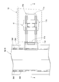
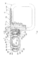
- FIG. 5 is a cross-sectional view taken along the line AA in FIG. 4.
- FIG. 1 It is a perspective view of the 2nd article mounting part with which the cart apparatus concerning one embodiment of the present invention is provided. It is a perspective view (a 2nd article mounting part is shown with a dashed-two dotted line) containing the support body with which the cart apparatus which concerns on one Embodiment of this invention is provided, and the support bracket of a 2nd article mounting part. It is a perspective view containing the support body with which the cart apparatus which concerns on one Embodiment of this invention is equipped, the 2nd article mounting part, and the support bracket of a 2nd article mounting part. It is a top view of the three views of the support bracket of the second article placement portion provided in the cart device according to the embodiment of the present invention.
- FIG. 8 is a sectional view taken along line BB in FIG. It is CC sectional drawing of FIG. It is a perspective view of the components interposed between the support bracket of the 2nd article mounting part with which the cart apparatus concerning one embodiment of the present invention is provided, and the 2nd article mounting part.
- FIG. 6 is a DD sectional view of FIG.
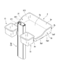
- FIG. 1 is a perspective view of a cart apparatus according to an embodiment of the present invention.
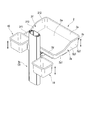
- FIG. 2 is a perspective view including a first article placement section and a second article placement section of the cart device according to the embodiment of the present invention.
- FIG. 3 is a perspective view including a first article placement section and a second article placement section provided in the cart device according to the embodiment of the present invention. From the state shown in FIG. It is the figure which moved the 2nd article mounting part of the below.
- the side where the user grips the handle 5e and faces the cart apparatus 1 is the rear side
- the side where the user pushes the handle 5e to advance the cart apparatus 1 is the front side.
- a direction connecting the rear side and the front side is defined as a front-rear direction or a depth direction.
- the horizontal direction orthogonal to the front-rear direction is the width direction.
- the right side (the right front side of the paper surface shown in FIG. 1) is the right side
- the left side (the left rear side of the paper surface shown in FIG. 1) is the left side. To do.
- the cart apparatus 1 is a fixture that carries and transports articles such as document files and medicine bottles in offices and hospitals.
- a cart body 3 installed on the floor, a pocket tray (second article placement unit, article placement member) 10 supported by the cart body 3, and a pocket that supports the pocket tray 10.
- the pocket tray 10 and the main tray 2 are mounted on the cart body 3 so that the position in the vertical direction can be changed.
- the cart body 3 includes a leg portion (first base portion) 3 a, a support base (support body) 3 b, and a lifting operation portion (not shown).
- the leg portion 3a includes four linear leg rods 3a1, a second base portion 3a2 to which the bases of these leg rods 3a1 are connected, a caster 3a3 attached to the tip of each leg rod 3a1, and casters And a first lock portion 3a4 for locking 3a3.
- the cart device 1 can run by rolling in a state in which the casters 3a3 of the leg portions 3a are in contact with the floor surface. Moreover, the movement of the cart apparatus 1 is controlled by locking the caster 3a3 by the first lock portion 3a4.
- FIG. 4 is a front view including the support base 3 b and the pocket tray support mechanism 11.
- FIG. 5 is a cross-sectional view taken along the line AA in FIG. 4 and 5, only one pocket tray support mechanism 11 is shown.
- the support base 3 b includes an outer column unit 3 b 1 and an inner column unit 3 b 2.
- the outer column unit 3b1 includes an outer 3b3 that is a hollow columnar portion standing on a second base portion 3a2 (see FIG. 1, the same applies hereinafter) of a leg 3a (see FIG. 1, the same applies hereinafter), and an outer And a shelf column 3b4 fixed to 3b3.
- first groove portions 3b5 are formed on each of the front side and the rear side of the cart device 1. These two first groove portions 3b5 are formed so as to extend in the vertical direction while being parallel to each other.
- the shelf column 3b4 is fitted in each of the first groove portions 3b5 of the outer 3b3.
- a total of four shelf columns 3b4 are provided, two on each of the front side and the rear side of the cart device 1.
- Each shelf column 3b4 is formed with locking holes 3b6 at a constant pitch in the vertical direction. These locking holes 3b6 are places into which locking claws 11c10, 4g3 (described later) provided in tray support means 11, 4 (described later) are inserted.
- the inner column unit 3b2 is inserted into the outer column 3b3 of the outer column unit 3b1, and has a hollow columnar part 3b7 with the top plate unit 5 fixed to the upper end, and is supported on the side of the columnar part 3b7 and is outside. And a roller 3b8 that contacts the inner wall surface of the outer 3b3 of the column unit 3b1.
- Such an inner column unit 3b2 is movable in the vertical direction inside the outer 3b3 of the outer column unit 3b1 by rolling the roller 3b8.
- the support base 3b When the inner column unit 3b2 protrudes greatly upward from the outer column unit 3b1, the support base 3b is extended as a whole, and the top unit 5 (see FIG. 1, the same applies hereinafter) is arranged at a high position. Is done.
- the support base 3b is contracted as a whole, and the top unit 5 is disposed at a low position.
- the elevating operation unit (not shown; the same applies hereinafter) includes an operation lever (not shown) and a lock mechanism (not shown).
- the operation lever is disposed below the handle 5e, and when operated, the lock of the inner column unit 3b2 by the lock mechanism is released.
- the lock mechanism fixes the inner column unit 3b2 to the outer column unit 3b1, and the lock is released only when the operation lever is operated.
- FIG. 6 is a perspective view of the pocket tray 10.
- the pocket tray 10 includes a bottom plate 10a, a peripheral wall portion 10b erected on the edge of the bottom plate 10a, a downward claw 10j and an engagement piece 10k formed on the front portion of the peripheral wall portion 10b. It has.
- the bottom plate 10a is an article placement surface having a flat upper surface, and is a plate-like portion that supports the placed article from below.
- the bottom plate 10a has a substantially square shape.
- the peripheral wall portion 10b is a wall portion erected on the edge portion of the bottom plate 10a so as to surround the bottom plate 10a, a front wall 10d erected from the front side of the cart device 1 in the bottom plate 10a, and a cart device in the bottom plate 10a.
- a rear wall 10e erected from one rear side, a first side wall 10f erected from a first side in the width direction of the cart device 1 in the bottom plate 10a, and a width direction of the cart device 1 in the bottom plate 10a.
- a second side wall 10g erected from the second side.
- a folded wall portion 10h folded outward is continuously provided at the upper end portions of the front wall 10d, the first side wall 10f, the rear wall 10e, and the second side wall 10g.
- the downward claws 10j are provided at four locations on the front wall 10d of the peripheral wall portion 10b so as to be separated in the width direction and the vertical direction.
- Each downward claw 10j includes a first flat surface portion 10j1 protruding along the horizontal plane from the front wall 10d, and a curved portion 10j2 formed to bend downward gradually toward the front from the end of the first flat surface portion 10j1. And a second flat surface portion 10j3 extending along the vertical plane from the end of the curved portion 10j2.
- the downward nail 10j has a downward hook shape.
- the downward claws 10j are formed to be elastically deformable.
- the interposition member 11b is formed of a synthetic resin such as PP (polypropylene).
- the engaging piece 10k is disposed between the two downward claws 10j disposed on the lower side of the downward claws 10j spaced apart from each other on the front wall 10d of the peripheral wall portion 10b.
- the engagement piece 10k protrudes forward from the front wall 10d and is formed horizontally long.
- the dimension of the pocket tray 10 in the front-rear direction in the cart device 1 is longer than the dimension of the support base 3b in the front-rear direction.
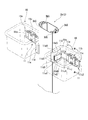
- pocket tray support mechanism As shown in FIG. 1, in this embodiment, two pocket tray support mechanisms 11 are provided for the cart body 3. These pocket tray support mechanisms 11 are arranged on both sides in the width direction of the cart apparatus 1 with the support base 3b interposed therebetween. Each pocket tray support mechanism 11 is detachably attached to the support base 3 b and supports the pocket tray 10. Since these pocket tray support mechanisms 11 have the same configuration except that they are arranged in different directions, only one of them will be described in the following description.
- FIG. 7 is a perspective view including the support base 3b and the pocket tray support mechanism 11 (the pocket tray 10 is indicated by a two-dot chain line).
- FIG. 8 is a perspective view including the support base 3 b, the pocket tray 10, and the pocket tray support mechanism 11.
- the pocket tray support mechanism 11 includes a bracket member (support bracket for the second article placement portion) 11a and an interposition member 11b.
- the bracket member 11a has a hanger part 11c, a cover part 11d, and a second lock part 11e.
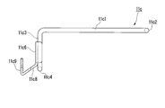
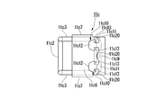
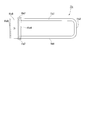
- FIGS. 9A to 9C are three views of the hanger portion 11c.
- FIG. 9A is a top view
- FIG. 9B is a side view
- FIG. 9C is a front view
- FIG. 10 is a partial perspective view of the bracket member 11a.
- the hanger portion 11c includes two straight wire portions 11c1, a first connecting wire portion 11c2, a bent wire portion 11c3, a second connecting wire portion 11c4, and a main plate shape. It has a portion 11c6, an end plate-like portion 11c7, a first bent plate-like portion 11c8, a second bent plate-like portion 11c9, and a locking claw (locking portion) 11c10.
- each straight wire portion 11c1 is engaged with the downward claw 10j of the pocket tray 10 with an intervening member 11b described later interposed therebetween.
- the two straight wire portions 11c1 are spaced apart from each other in the vertical direction corresponding to the vertical interval between the downward claws 10j.
- the 1st connection wire part 11c2 has connected the edge parts of the 1st end (width direction outer side of the cart apparatus 1) of the two straight wire parts 11c1.
- the bent wire portion 11c3 is bent along the side surface of the support base 3b from the end portion of the second end (the inner side in the width direction of the cart device 1) of each straight wire portion 11c1.
- the second connecting wire portion 11c4 connects the rear ends of the two bent wire portions 11c3.
- these straight wire part 11c1, the 1st connection wire part 11c2, the bending wire part 11c3, and the 2nd connection wire part 11c4 are integrally formed by the wire steel rod.
- the main plate-like portion 11c6 is provided along the surface of the two bent wire portions 11c3 on the support base 3b side.
- the end plate-like portion 11c7 is bent from the upper and lower ends of the main plate-like portion 11c6.
- Each end plate-like portion 11c7 is disposed along the upper and lower surfaces of the two bent wire portions 11c3.
- the first bent plate-like portion 11c8 is bent from the rear end portion of the main plate-like portion 11c6 and is gradually inclined toward the center in the width direction of the cart device 1 as it goes rearward.
- the second bent plate-like portion 11c9 is provided to be bent forward from the rear end portion of the first bent plate-like portion 11c8.
- the second bent plate-like portion 11c9 is disposed in the first groove portion 3b5 of the support base 3b.
- the latching claws 11c10 are provided at two positions at the end of the second bent plate-like portion 11c9 so as to be separated in the vertical direction.
- the contact wall part 11c20 which protrudes toward the latching claw 11c10 is provided in the edge part of the 2nd bending plate-shaped part 11c9.
- the contact wall portion 11c20 is provided at the upper and lower ends of the second bent plate-like portion 11c9 and at three locations between the upper locking claw 11c10 and the lower locking claw 11c10.
- each locking claw 11c10 has a base portion 11c11 provided at an end of the second bent plate-like portion 11c9 and a width that is continuous with the base portion 11c11 and wider than the vertical width of the base portion 11c11. And the engaging claw portion 11c13 extending from the upper and lower ends of the wide portion 11c12 toward the end of the second bent plate-like portion 11c9.
- the main plate-like portion 11c6, the end plate-like portion 11c7, the first bent plate-like portion 11c8, the second bent plate-like portion 11c9, and the locking claw 11c10 are integrally formed of sheet metal or the like.
- the bent wire portion 11c3 is connected to the upper and lower ends of the main plate portion 11c6 and the end plate portion 11c7 by welding or the like.
- the hanger part 11c is symmetrical with respect to the center in the vertical direction.
- the cover portion 11d has a fixed wall portion 11d1, an end wall portion 11d2, an extending wall portion 11d3, and an upper and lower wall portion 11d4.
- the fixed wall portion 11d1 is disposed along the first bent plate portion 11c8 of the hanger portion 11c.
- the fixed wall portion 11d1 is fixed to the first bent plate-like portion 11c8.
- the end wall portion 11d2 is bent from the inner end in the width direction of the cart device 1 in the fixed wall portion 11d1, and is a corner portion between the first bent plate-like portion 11c8 and the second bent plate-like portion 11c9 of the hanger portion 11c. It is arranged to cover.
- the extending wall portion 11d3 is formed so as to extend forward from the upper and lower end portions at the end portion on the outer side in the width direction of the cart device 1 of the fixed wall portion 11d1.
- the extending wall portion 11d3 is disposed on the outer side in the width direction in the cart device 1 of the bending wire portion 11c3 of the hanger portion 11c.
- the upper and lower wall parts 11d4 are formed so as to cover the upper side and the lower side of the hanger part 11c from the respective extended wall parts 11d3.
- the cover portion 11d is symmetric with respect to the center in the vertical direction.
- the second lock portion 11e includes a shaft locking portion 11e1, an extending wall portion 11e2, a pressing projection 11e3, a bent wall portion 11e4, a knob portion 11e5, and a locking claw portion 11e6.
- the shaft locking portion 11e1 is formed in an arc shape so as to be locked to the outer peripheral surface of the second connecting wire portion 11c4 of the hanger portion 11c.
- the shaft locking portion 11e1 is disposed between the upper extending wall portion 11d3 and the lower extending wall portion 11d3 of the cover portion 11d.
- the extending wall portion 11e2 extends forward from the end portion of the shaft locking portion 11e1, and is disposed between the upper bending wire portion 11c3 and the lower bending wire portion 11c3 of the hanger portion 11c.
- the pressing protrusion 11e3 protrudes from the inner surface in the width direction in the cart device 1 of the extending wall portion 11e2 toward the main plate-like portion 11c6 of the hanger portion 11c.
- the tip end portion of the pressing protrusion 11e3 is in contact with the main plate portion 11c6.
- the bent wall portion 11e4 is inclined so as to gradually move forward from the end portion of the extending wall portion 11e2 toward the inner side in the width direction of the cart device 1.
- the knob portion 11e5 is formed to protrude forward at the front end portion of the bent wall portion 11e4.
- the locking claw portion 11e6 is formed to be recessed forward at the rear end portion of the bent wall portion 11e4.
- the locking claw portion 11e6 is locked to a protrusion 3b9 on one side (outside in the width direction of the cart device 1) sandwiching the first groove 3b5 in the outer 3b3 of the support base 3b.
- the second lock portion 11e has a symmetrical shape with the center in the vertical direction as a boundary.
- FIG. 11 is a cross-sectional view taken along the line BB in FIG. 12 is a cross-sectional view taken along the line CC of FIG.
- FIG. 13 is a perspective view of the interposition member 11b.
- the interposition member 11 b includes a wire fitting part 11 b 1, an upper and lower connecting part 11 b 2, a central wall part 11 b 3, a left and right connecting part 11 b 4, a retaining piece 11 b 8, and a support wall part. 11b5 and lever piece 11b6.
- the interposition member 11b is formed to be elastically deformable.
- the interposition member 11b is formed of a synthetic resin such as PP (polypropylene).
- the wire fitting portions 11b1 are arranged at four positions apart from each other in the width direction and the vertical direction of the cart device 1.
- the wire fitting part 11b1 arranged on the upper side opens toward the rear upper part.
- the wire fitting portion 11b1 disposed on the lower side opens toward the rear lower portion.
- the upper wire fitting portion 11b1 is engaged with the upper straight wire portion 11c1 of the bracket member 11a while being elastically deformed.
- the lower wire fitting portion 11b1 is engaged with the lower straight wire portion 11c1 of the bracket member 11a while being elastically deformed.
- the upper and lower connecting portion 11b2 connects the upper wire fitting portion 11b1 and the lower wire fitting portion 11b1.
- the upper and lower connecting portions 11b2 are formed in a plate shape and are disposed along a vertical plane.
- the upper and lower connecting portions 11b2 are provided at two positions apart from each other in the width direction of the cart device 1 so as to connect the width direction first sides of the cart device 1 and the width direction second sides.
- the central wall portion 11b3 is disposed between the pair of upper and lower connecting portions 11b2.
- the central wall portion 11b3 is formed in a plate shape and is disposed along the vertical plane.
- the left and right connecting portions 11b4 connect the central wall portion 11b3 and the upper and lower connecting portions 11b2 on both sides in the width direction of the cart device 1 respectively.
- the left and right connecting portions 11b4 are formed in a plate shape and are arranged along a vertical plane.
- the left and right connecting portions 11b4 are provided so as to be positioned at the center in the vertical direction of the central wall portion 11b3. That is, the left and right connecting portions 11b4 and the central wall portion 11b3 are not connected on the upper and lower sides.
- the retaining piece 11b8 protrudes from the central wall portion 11b3 toward the front wall 10d side of the pocket tray 10.
- the retaining pieces 11b8 are provided on the upper and lower portions of the central wall portion 11b3, respectively.
- the retaining piece 11b8 has an engaging surface 11b9 formed along a horizontal plane.
- the support wall portion 11b5 is provided at each of the upper end portion and the lower end portion of the central wall portion 11b3.
- the upper support wall portion 11b5 is curved from the lower surface of the upper straight wire portion 11c1 along the front surface.
- the lower support wall portion 11b5 is curved from the upper surface of the lower straight wire portion 11c1 along the front surface.
- the lever piece 11b6 is continuously provided on each support wall portion 11b5.
- the upper lever piece 11b6 is formed to extend upward from the support wall portion 11b5.
- the lower lever piece 11b6 is formed to extend downward from the support wall portion 11b5.
- the intervening member 11b has a symmetrical shape with respect to the center in the vertical direction, and is formed symmetrically with respect to the center in the width direction.
- the pocket tray support mechanism 11 including the bracket member 11a and the interposition member 11b has a symmetrical shape with respect to the center in the vertical direction. Thereby, it can provide in the width direction both sides of the cart apparatus 1 by inverting the upper and lower sides of the pocket tray support mechanism 11.
- FIG. 14 is a cross-sectional view taken along the line DD of FIG.
- FIG. 15 is a perspective view for explaining the operation of attaching the pocket tray 10 to the support base 3b.
- the wire fitting portion 11b1 of the interposed member 11b is fitted into the straight wire portion 11c1 of the bracket member 11a.
- the locking claw 11 c 10 of the hanger portion 11 c is locked in the locking hole 3 b 6 of the shelf column 3 b 4 of the cart body 3.
- the locking claw 11c10 has the same vertical arrangement pitch as the arrangement pitch of the locking holes 3b6 of the shelf columns 3b4 of the cart body 3.
- the length from the upper end of the upper engaging claw portion 11c13 to the lower end of the lower engaging claw portion 11c13 of the locking claw 11c10 is slightly shorter than the vertical length of the locking hole 3b6.
- the latching claw 11c10 passes through the latching hole 3b6, and the latching claw 11c10 inserted into the latching hole 3b6 is moved downward, so that the base 11c11 of the latching claw 11c10 becomes the shelf column. It arrange
- the locking claw portion 11e6 of the second lock portion 11e is locked to the protrusion 3b9 (see FIG. 5, the same applies hereinafter) of the support base 3b.
- the latching claw part 11e6 is latched by the protrusion part 3b9 of the support base 3b, while the shaft latching part 11e1 is engaged with the 2nd connection wire part 11c4 of the hanger part 11c.
- the 2nd lock part 11e is attached to hanger part 11c and support base 3b.
- claw 10j of the pocket tray 10 is engaged with the wire fitting part 11b1 with respect to the wire fitting part 11b1 of the interposition member 11b by which the straight wire part 11c1 is fitted.
- the pocket tray 10 is moved downward.
- the engaging piece 10k of the pocket tray 10 gets over the retaining piece 11b8 below the interposed member 11b.
- the linear wire part 11c1 by which the interposition member 11b was fitted is arrange
- the second flat surface portion 10j3 of the downward claw 10j comes into contact with the front surface of the wire fitting portion 11b1, and the rearward movement of the pocket tray 10 is restricted. Further, the upper retaining piece 11b8 abuts against the front wall 10d of the pocket tray 10 and the forward movement of the pocket tray 10 is restricted. Further, the engagement piece 10k of the pocket tray 10 comes into contact with the engagement surface 11b9 of the interposition member 11b, and the upward movement of the pocket tray 10 is restricted. In this way, the mounting of the pocket tray 10 on the side of the support base 3b is completed.
- the straight wire portion 11c1 of the hanger portion 11c is disposed on substantially the same plane as the front surface of the support base 3b.
- the pocket tray 10 is disposed on the rear side of the straight wire portion 11c1 of the hanger portion 11c. Further, the dimension of the pocket tray 10 in the front-rear direction in the cart device 1 is longer than the dimension in the front-rear direction of the support base 3b. Therefore, the pocket tray 10 protrudes rearward from the support base 3b.
- bracket member 11a is mounted in the locking hole 3b6 on the rear side of the support base 3b.
- the bracket member 11a can be mounted in the locking hole 3b6 on the front side of the support base 3b.
- the latching claw part 11e6 of the 2nd lock part 11e is removed from the protrusion 3b9 of the support base 3b. Further, the hanger part 11c is moved slightly upward and moved backward. As a result, the wide portion 11c12 of the locking claw 11c10 of the hanger portion 11c passes through the locking hole 3b6 of the support base 3b, and the pocket tray support mechanism 11 and the pocket tray 10 are detached from the support base 3b.
- the locking claw 11 c 10 is locked in the locking hole 3 b 6 formed at a height position different from the original position, so that the position in the vertical direction can be appropriately adjusted.
- the pocket tray 10 can be mounted on the support base 3b side.
- FIG. 16A and 16B are perspective views of the main tray 2
- FIG. 16A is a perspective view seen from above
- FIG. 16B is a perspective view seen from below
- 17A to 17C are three views of the main tray 2.
- FIG. 17A is a bottom view
- FIG. 17B is a side view
- FIG. 17C is a front view.
- the main tray 2 includes a bottom plate 2a, a peripheral wall portion 2b erected on the edge of the bottom plate 2a, and a protrusion 2c formed on the lower surface of the bottom plate 2a.
- the side shown in FIG. 17C is referred to as a front side
- the side opposite to the front side is referred to as a back side.
- the bottom plate 2a is an article placement surface having a flat upper surface, and is a plate-like portion that supports the placed article from below.
- the bottom plate 2a has a substantially rectangular shape with a short depth direction and a long width direction.
- the peripheral wall portion 2b is a wall portion erected on the edge of the bottom plate 2a so as to surround the bottom plate 2a.
- the front wall 2d erected from the long side on the front side of the bottom plate 2a, and the length on the back side of the bottom plate 2a.
- a second side wall 2g to be provided.
- the height in the vertical direction of the front wall 2d is set lower than that of the back wall 2e. That is, the height in the vertical direction of the back wall 2e is set higher than that of the front wall 2d. As a result, the upper end of the front wall 2d is positioned lower than the upper end of the back wall 2e.
- the first side wall 2f is connected to the left end of the front wall 2d and the left end of the back wall 2e.
- the second side wall 2g is connected to the right end of the front wall 2d and the right end of the back wall 2e.
- the first side wall 2f has a front side part 2f1, a back side part 2f2, and a first intermediate part 2f3.
- the front side portion 2f1 is a part that is connected to the front wall 2d and has the same height as the front wall 2d.
- the back side portion 2f2 is a part that is connected to the back wall 2e and has the same height as the back wall 2e.
- the first intermediate portion 2f3 is disposed between the front side portion 2f1 and the back side portion 2f2, and the upper end thereof is inclined so as to connect the upper end of the front side portion 2f1 and the upper end of the back side portion 2f2 in a straight line. It is a part.
- the second side wall 2g has a front side part 2g1, a back side part 2g2, and a first intermediate part 2g3.
- the front side portion 2g1 is a portion that is connected to the front wall 2d and has the same height as the front wall 2d.
- the back side part 2g2 is a part that is connected to the back wall 2e and has the same height as the back wall 2e.
- the first intermediate part 2g3 is disposed between the front side part 2g1 and the back side part 2g2, and the upper end is inclined so as to connect the upper end of the front side part 2g1 and the upper end of the back side part 2g2 in a straight line. It is a part. As shown in FIG. 16A, the first intermediate portion 2f3 of the first side wall 2f and the first intermediate portion 2g3 of the second side wall 2g are provided at the same location in the depth direction.
- the height of the peripheral wall 2b is low on the front side and the height of the peripheral wall 2b is high on the back side.
- An area surrounded by the portion 2b is an article storage area.
- the front side of the storage area of the main tray 2 (hereinafter referred to as the front-side storage area Ra) has a low peripheral wall portion 2b, so that the article can be easily taken in and out and is easily visible. For example, it is an area suitable for accommodating small articles.
- the back side of the storage area of the main tray 2 (hereinafter referred to as the back side storage area Rb) has a high peripheral wall 2b, so that even if a tall article is tilted by running vibration of the cart device 1 or the like, the peripheral wall The region can be supported by the portion 2b, and is an area suitable for stably storing, for example, a tall article.
- the dimension of the width direction in the cart apparatus 1 of the main tray 2 is longer than the dimension of the width direction of the support base 3b.
- the protrusion 2c is a portion protruding downward from the lower surface of the bottom plate 2a.
- a plurality are formed as shown in FIG. 17A.
- these protrusions 2 c are grouped into a left protrusion group 2 cA disposed on the left side of the main tray 2 and a right protrusion group 2 cB disposed on the right side of the main tray 2.
- the left projection group 2cA includes a front projection 2c1, a rear projection 2c2, a front central projection 2c3, and a rear central projection 2c4 as projections 2c.
- the front side protrusion 2c1, the back side protrusion 2c2, the front side center protrusion 2c3, and the back side center protrusion 2c4 are arranged substantially linearly in the depth direction.
- the front side protrusion 2c1 includes a first hanging portion 2c11 that hangs downward from the lower surface of the main tray 2, and an extending portion 2c12 that protrudes toward the right side of the main tray 2 from the lower end of the first hanging portion 2c11.
- the extending portion 2c12 is a substantially rectangular plate portion whose long side is horizontally arranged along the depth direction of the main tray 2, and the right side is connected to the lower end of the first drooping portion 2c11 so that the main tray is 2 and a certain gap from the lower surface.
- the front side protruding portion 2c1 is disposed on the most front side of the main tray 2 in the left side protruding group 2cA.
- the rear side protrusion 2c2 has the same shape as the front side protrusion 2c1, and includes a first hanging part 2c21 that hangs downward from the lower surface of the main tray 2, and a lower end of the first hanging part 2c21. And an extending portion 2c22 protruding toward the right side.
- the extending portion 2c22 is a substantially rectangular plate portion whose long side is horizontally arranged along the depth direction of the main tray 2, and the right side is connected to the lower end of the first hanging portion 2c21 to connect the main tray. 2 and a certain gap from the lower surface.
- the separation distance from the extension portion 2c22 to the lower surface of the main tray 2 is set to be the same as the separation distance from the extension portion 2c12 of the front projection 2c1 to the lower surface of the main tray 2.
- the back side protrusion 2c2 is disposed on the back side of the main tray 2 most in the left protrusion group 2cA.
- the front side central projection 2c3 and the back side central projection 2c4 are arranged between the front side projection 2c1 and the back side projection 2c2.
- the front side central projection 2c3 is disposed on the front side of the main tray 2
- the back side central projection 2c4 is disposed on the back side of the main tray 2. Yes.
- insertion clearance S1 in which the below-mentioned engagement projection 4f with which the main tray support mechanism 4 is provided is inserted is formed.
- the front-side central protrusion 2c3 is arranged slightly displaced toward the center in the width direction of the main tray 2 with respect to the front-side protrusion 2c1 and the back-side protrusion 2c2.
- the front side central projection 2c3 has a slope 2c31 that is inclined with respect to the depth direction toward the front side of the main tray 2.
- the inclined surface 2c31 is a surface that extends from the front side of the main tray 2 toward the insertion gap S1 toward the center in the width direction of the main tray 2, and attaches and detaches the main tray 2 with the front side facing the cart body 3 side. Sometimes the engaging projection 4f is guided.
- the rear side central projection 2c4 is arranged slightly displaced toward the central portion in the width direction of the main tray 2 with respect to the front side projection 2c1 and the rear side projection 2c2. Yes.
- the back side central projection 2c4 has a slope 2c41 that is inclined with respect to the depth direction toward the back side of the main tray 2.
- the inclined surface 2c41 is a surface that extends from the back side of the main tray 2 toward the insertion gap S1 toward the center in the width direction of the main tray 2, and attaches and detaches the main tray 2 with the back side facing the cart body 3 side. Sometimes the engaging projection 4f is guided.
- the front side central projection 2c3 and the back side central projection 2c4 are symmetrical with respect to the center of the main tray 2 in the depth direction.
- the right projection group 2cB includes a front side projection 2c5, a back side projection 2c6, a front side central projection 2c7, and a back side central projection 2c8 as projections 2c.
- the front-side protrusion 2c5, the back-side protrusion 2c6, the front-side center protrusion 2c7, and the back-side center protrusion 2c8 included in the right-side protrusion group 2cB are symmetrical to the left-side protrusion group 2cA.
- the front side protrusion 2c5 is symmetrical to the front side protrusion 2c1 of the left protrusion group 2cA, and includes a first hanging portion 2c51 and an extending portion 2c52.
- the back side protrusion 2c6 has a symmetrical shape with the back side protrusion 2c2 of the left protrusion group 2cA, and includes a first hanging part 2c61 and an extending part 2c62.
- the front side central projection 2c7 is symmetrical with the front side central projection 2c3 of the left projection group 2cA, and has an inclined surface 2c71.
- the back side central projection 2c8 has a symmetrical shape with the back side central projection 2c4 of the left projection group 2cA and has an inclined surface 2c81. Further, an insertion gap S2 into which an engagement protrusion 4f described later included in the main tray support mechanism 4 is inserted is formed between the front side central protrusion 2c7 and the back side central protrusion 2c8.
- FIG. 18 is a perspective view including the cart body 3 and the main tray support mechanism 4 (a perspective view in which the main tray 2 is omitted).
- two main tray support mechanisms (support means, support brackets for the first article placement unit) 4 are provided for the cart body 3. These main tray support mechanisms 4 are spaced apart in the vertical direction, and each support the main tray 2 in a detachable manner. Since these main tray support mechanisms 4 have the same configuration except that they are arranged at different heights, only one of them will be described in the following description.
- FIG. 19 is a perspective view of the main tray support mechanism 4 as viewed from above with the main tray 2 removed.
- FIG. 20 is a perspective view of the main tray support mechanism 4 as viewed from below with the main tray 2 removed.
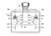
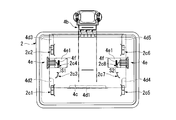
- FIG. 21 is a bottom view of the main tray support mechanism 4 as viewed from below with the main tray 2 attached.
- FIG. 22 is an enlarged side view of a part of the main tray support mechanism 4 on the cart body 3 side with the main tray 2 removed.
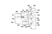
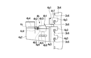
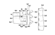
- the main tray support mechanism 4 includes a support unit 4a and a lock unit 4b.
- the support unit 4a includes a third base portion 4c, a contact portion 4d, a tray detachment operation portion 4e, an engagement protrusion 4f, and a bracket portion 4g.
- the third base portion 4c is a plate-like portion that directly or indirectly supports the contact portion 4d, the tray detachment operation portion 4e, and the engagement protrusion 4f.
- the third base portion 4 c has a substantially rectangular shape with a smaller area than the lower surface of the main tray 2, and the main tray 2 is exposed so that the vicinity of both left and right ends of the lower surface of the main tray 2 is exposed. 2 is covered.
- the regions on both sides of the lower surface of the main tray 2 with the third base portion 4c sandwiched are exposed.
- the exposed area of the lower surface of the main tray 2 is used as an area that is gripped by the operator when the main tray 2 is detached from the main tray support mechanism 4 (hereinafter referred to as a holding area Ha).
- a holding area Ha an area that is gripped by the operator when the main tray 2 is detached from the main tray support mechanism 4
- a holding area Ha an area that is gripped by the operator when the main tray 2 is detached from the main tray support mechanism 4
- the front side edge 4c1, the left side edge 4c2, and the right side edge 4c3 of the third base part 4c are bent upward as shown in FIG. Further, the rear edge portion 4c4 of the third base portion 4c is bent downward.
- the front side edge part 4c1, the left side edge part 4c2, and the right side edge part 4c3 of the third base part 4c support the contact part 4d that is integrally connected.
- an opening 4c5 through which an operation plate 4e1 (to be described later) of the tray detachment operation unit 4e is inserted is formed in the center in the front-rear direction on the left side edge 4c2 and the right side edge 4c3.
- the rear edge 4c4 of the third base portion 4c serves as a contact surface of a coil spring 4b2 described later of the lock unit 4b.
- the contact part 4d is provided integrally with the front side edge part 4c1, the left side edge part 4c2, and the right side edge part 4c3 of the third base part 4c.
- the front center contact part 4d1, the left front contact part 4d2, the left rear contact part 4d3, the right front contact part 4d4, and the right rear contact part 4d5 is provided.
- the front center contact portion 4d1 extends rearward from the upper end of the front edge 4c1 of the third base portion 4c, and the upper surface is a contact surface that contacts the lower surface of the main tray 2.
- the left front contact portion 4d2 is provided at the front end of the left edge 4c2 of the third base portion 4c, and extends from the upper end of the left edge 4c2 toward the right.
- the left front contact portion 4d2 has a top surface that is in contact with the bottom surface of the main tray 2, and the top surface of the left front contact portion 4d2 is flush with the top surface of the front center contact portion 4d1. Is arranged.
- the left rear contact portion 4d3 is provided at the rear end portion of the left edge portion 4c2 of the third base portion 4c, and extends from the upper end of the left edge portion 4c2 toward the right side.
- the left rear contact portion 4d3 is also a contact surface whose upper surface is in contact with the lower surface of the main tray 2, and the upper surface of the left rear contact portion 4d3 is flush with the upper surface of the front center contact portion 4d1. Is arranged.
- the right front contact portion 4d4 is provided at the front end of the right edge 4c3 of the third base portion 4c, and extends from the upper end of the right edge 4c3 toward the left side.
- the front right contact portion 4d4 also has a top surface that is in contact with the bottom surface of the main tray 2, and the top surface of the right front contact portion 4d4 is flush with the top surface of the front center contact portion 4d1. Is arranged.
- the right rear contact portion 4d5 is provided at the rear end portion of the right edge portion 4c3 of the third base portion 4c, and extends from the upper end of the right edge portion 4c3 toward the left side.
- the upper right surface of the right rear contact portion 4d5 is also a contact surface that contacts the lower surface of the main tray 2, and the upper surface of the right rear contact portion 4d5 is flush with the upper surface of the front center contact portion 4d1. It is arranged to be.
- abutting portions 4d all have abutting surfaces of the same height that abut against the lower surface of the main tray 2.
- the main tray 2 is supported by being brought into contact with these contact surfaces. That is, the main tray 2 includes the upper surface of the front center contact portion 4d1, the upper surface of the left front contact portion 4d2, the upper surface of the left rear contact portion 4d3, the upper surface of the right front contact portion 4d4, and the right rear. It is supported from below by the upper surface of the side contact portion 4d5. Thereby, the downward movement of the main tray 2 is restricted.
- these contact portions 4d are formed from the upper ends of the front side edge portion 4c1, the left side edge portion 4c2, and the right side edge portion 4c3, which are bent upward as described above, from the third base portion 4c. It is formed to extend inward. For this reason, these contact parts 4d are arranged at a certain distance from the upper surface of the third base part 4c. That is, the contact portion 4d is disposed with a certain gap in the vertical direction between the upper surface of the third base portion 4c.
- the extension 2c12 of the front side protrusion 2c1 is inserted below the left front contact part 4d2, and the extension of the back side protrusion 2c2 2c22 is inserted below the left rear contact portion 4d3.
- the extending portion 2c52 of the front side protruding portion 2c5 is inserted below the right front contact portion 4d4, and the extending portion 2c62 of the back side protruding portion 2c6 is inserted below the right rear contact portion 4d5.
- the extended portion 2c22 of the rear side protruding portion 2c2 interferes with the left rear contact portion 4d3
- the extended portion 2c52 of the front side protruding portion 2c5 interferes with the right front side contact portion 4d4, and the rear side protruding portion 2c6.
- the extended portion 2c62 interferes with the right rear contact portion 4d5. Thereby, the upward movement of the main tray 2 is restricted.
- the extending portion 2c12 of the front side protruding portion 2c1 and the extending portion 2c22 of the back side protruding portion 2c2 are used. Interferes with the left edge portion 4c2 of the third base portion 4c. Further, the extending portion 2c52 of the front side protruding portion 2c5 and the extending portion 2c62 of the back side protruding portion 2c6 interfere with the right edge 4c3 of the third base portion 4c. As a result, movement of the main tray 2 in the left-right direction of the cart device 1 is restricted.
- the tray detachment operation part 4e is provided on each of the left side and the right side of the third base part 4c, and is arranged at the center part in the front-rear direction of the third base part 4c.
- the tray detachment operation unit 4e includes an operation plate 4e1 and an urging unit 4e2.
- the operation plate 4e1 is a plate-like member that is arranged in an inserted state in the opening 4c5 formed in the third base portion 4c with the front and back surfaces thereof directed in the vertical direction, and is an end facing the outside of the third base portion 4c.
- the grip part 4e3 is provided in the part.
- the operation plate 4e1 of the tray detaching operation unit 4e arranged on the left side of the third base unit 4c is provided with the gripping unit 4e3 at the end protruding to the left side from the opening 4c5. Further, the operation plate 4e1 of the tray detaching operation unit 4e disposed on the right side of the third base unit 4c is provided with a gripping unit 4e3 at an end protruding to the right side from the opening 4c5.
- the urging unit 4e2 is fixed to the lower surface of the third base portion 4c and accommodates a part of the lower portion of the operation plate 4e1.
- the urging unit 4e2 is provided with a spring (not shown) inside the cover, and urges the operation plate 4e1 toward the outside of the third base portion 4c.
- the urging unit 4e2 includes a stopper (not shown), and defines a movement limit position of the operation plate 4e1 toward the outside of the third base portion 4c.
- the movement limit position of the operation plate 4e1 is referred to as a reference position.
- the reference position of the operation plate 4e1 is such that the engagement protrusion 4f installed on the operation plate 4e1 is inserted into the insertion gap S1 (or insertion gap S2) of the main tray 2 in a state where the main tray 2 is mounted on the support unit 4a. It is set to the position where it is inserted into.
- the engagement protrusion 4f is formed on the operation plate 4e1.
- the operation plate 4e1 is a rod-like protrusion that is long in the front-rear direction, and the length in the front-rear direction is set slightly shorter than the insertion gap S1 of the main tray 2 and the length of the insertion gap S2 in the depth direction.
- the engagement protrusion 4f has an insertion gap S1 (or insertion gap) of the main tray 2 as shown in FIG. It is inserted in S2).
- the front side central protrusion part 2c3 and the back side central protrusion part of the main tray 2 are provided before and after the engagement protrusion 4f. 2c4 is arranged.
- the engagement protrusion 4 f interferes with the front-side center protrusion 2 c 3 or the back-side center protrusion 2 c 4, so that the front-rear direction of the main tray 2 Movement is restricted.
- the engagement protrusion 4f is inserted into the insertion gap S2, as shown in FIG.
- the front side central protrusion 2c7 and the back side central protrusion 2c8 of the main tray 2 are arranged before and after the engagement protrusion 4f. Is done.
- the engagement protrusion 4 f interferes with the front-side center protrusion 2 c 7 or the back-side center protrusion 2 c 8, and the main tray 2 moves in the front-rear direction. Movement is restricted. For this reason, the main tray 2 mounted on the support unit 4a cannot move in the front-rear direction of the cart device 1.
- the bracket part 4g includes a fifth base part 4g1 fixed to the support base 3b of the cart body 3 and two pieces extending forward from the fifth base part 4g1. Arm 4g2.
- the fifth base portion 4g1 is a portion that is substantially U-shaped when viewed from the vertical direction.
- a locking claw (locking portion) 4g3 is provided at the substantially U-shaped end portion.
- three locking claws 4g3 are arranged in each of two substantially U-shaped end portions in the vertical direction. These locking claws 4g3 have a vertical arrangement pitch of the locking holes 3b6 (see FIG. 4; see FIG. 4) of the shelf column 3b4 (see FIG.
- the bracket portion 4g (that is, the main tray support mechanism 4) is fixed to the cart body 3. Further, the bracket portion 4g fixed to the cart body 3 (that is, the main tray support mechanism 4) is lifted with respect to the cart body 3 so that the locking claw 4g3 is separated from the shelf column 3b4 and removed from the cart body 3. be able to.
- the shelf column 3b4 is formed with a plurality of locking holes 3b6 in the vertical direction.
- the bracket portion 4g (that is, the main tray support mechanism 4) can fix the fifth base portion 4g1 to an arbitrary position in the height direction of the support base 3b. That is, in this embodiment, the main tray support mechanism 4 can be attached to an arbitrary position of the shelf column 3b4 (attached portion) provided in a certain range of the support base 3b that is a part of the cart body 3.
- the fifth base portion 4g1 is formed between the uppermost locking claw 4g3 and the lowermost locking claw 4g3 among the three locking claws 4g3 arranged in the vertical direction.
- a slit 4g5 is formed on the surface.
- the slit 4g5 is a region where a wedge portion 4b7 of a lock member 4b1 (described later) of the lock unit 4b is inserted so as to be movable in the front-rear direction of the cart device 1.
- the arm 4g2 is disposed so as to be separated in the left-right direction of the cart device 1, and the root portion is fixed to the fifth base portion 4g1.
- These arms 4g2 have a plate shape in which the thickness in the left-right direction of the cart device 1 is reduced, and the upper ends thereof are fixed to the lower surface of the third base portion 4c.
- Such an arm 4g2 supports the fifth base portion 4g1 from below.
- a slit 4g4 extending in the front-rear direction is formed in the vicinity of the base of the arm 4g2.
- a claw portion 4b6 of a lock member 4b1 described later of the lock unit 4b is inserted into the slit 4g4.
- the slit 4g4 is set longer than the width of the claw portion 4b6 in the front-rear direction of the cart device 1.
- the claw portion 4b6 can be moved in the front-rear direction of the cart device 1 in a state where the claw portion 4b6 is inserted into the slit 4g4.
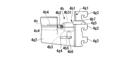
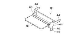
- the lock unit 4b includes a lock member 4b1 and a coil spring 4b2, as shown in FIG. 23A and 23B are perspective views of the lock member 4b1, FIG. 23A is a perspective view seen from the front side of the cart device 1, and FIG. 23B is a perspective view seen from the rear side of the cart device 1.
- the lock member 4b1 includes a second base portion 4b3 in which a second groove portion 4b31 for a worker to hang a finger is formed, and extends from the second base portion 4b3 to the front side of the cart device 1.
- Extended plate 4b4 second hanging portion 4b5 hanging downward from second base portion 4b3, claw portion 4b6 projecting outward from the lower end of second hanging portion 4b5, and rearward from second base portion 4b3
- a wedge portion 4b7 provided so as to protrude.
- the second base portion 4b3 is formed long in the left-right direction, and is disposed between the arms 4g2 of the bracket portion 4g (see FIG. 20).
- the second base portion 4b3 is disposed so as to be movable in the front-rear direction between the third base portion 4c of the support unit 4a and the fifth base portion 4g1 of the bracket portion 4g.
- the second groove portion 4b31 described above is formed along the direction in which the second base portion 4b3 extends.
- the extension plate 4b4 is disposed above the upper surface of the third base portion 4c of the support unit 4a in parallel with the upper surface of the third base portion 4c. The extension plate 4b4 is moved along the upper surface of the third base portion 4c of the support unit 4a when an operator puts a finger on the second groove portion 4b31 and pulls the lock member 4b1.
- the second hanging parts 4b5 are respectively installed at both ends in the left-right direction of the second base part 4b3.
- the claw portion 4b6 is inserted into a slit 4g4 formed in the arm 4g2 of the bracket portion 4g.
- the movement of the lock member 4b1 in the left-right direction and the up-down direction with respect to the bracket portion 4g is restricted. That is, the lock member 4b1 can be moved only in the front-rear direction within the range of the length in the front-rear direction of the slit 4g4 by inserting the claw portion 4b6 into the slit 4g4.
- the wedge portions 4b7 are respectively installed at both end portions in the left-right direction of the second base portion 4b3. These wedge portions 4b7 are arranged in slits 4g5 formed in the fifth base portion 4g1 of the bracket portion 4g as shown in FIG. The wedge portion 4b7 is moved in the front-rear direction along the slit 4g5 when the lock member 4b1 is moved in the front-rear direction. Further, the length in the front-rear direction of the wedge portion 4b7 is arranged between the locking claws 4g3 of the bracket portion 4g when the distal end portion is viewed from the vertical direction when the lock member 4b1 is moved to the rearmost side.
- the distal end portion is set so as to be pulled out from between the locking claws 4g3 of the bracket portion 4g when viewed from the vertical direction. Furthermore, the thickness in the vertical direction of the wedge portion 4b7 can be inserted into a gap formed above the locking claw 4g3 in a state where the locking claw 4g3 of the bracket portion 4g is locked to the shelf column 3b4. It is set so that the locking hole 3b6 can be filled together with the locking claw 4g3. Such a wedge portion 4b7 can be inserted into a gap formed above the locking claw 4g3. When the locking hole 3b6 is filled together with the locking claw 4g3, the locking claw 4g3 can be moved upward.
- the support unit 4a (ie, the main tray support mechanism 4) cannot be detached from the cart body 3 (see FIG. 26A). That is, the main tray support mechanism 4 is locked with respect to the cart body 3 in a state of extending forward from the support base 3b.
- the coil spring 4b2 is wound around a protrusion formed on the lower surface of the extending plate 4b4, and the tip end abuts on the rear edge 4c4 of the third base portion 4c of the support unit 4a. As shown in FIG. 21, three coil springs 4b2 are arranged in the left-right direction. Such a coil spring 4b2 biases the lock member 4b1 to the rear side (that is, the support base 3b side of the cart body 3). For this reason, in a state in which an external force other than the urging force of the coil spring 4b2 is not acting on the lock member 4b1, the lock member 4b1 is urged to the rear side (that is, the cart body 3 and the support base 3b side). Therefore, when the operator does not move the lock member 4b1 to the front side, the wedge portion 4b7 described above can be inserted into the gap formed above the locking claw 4g3, and the main tray support mechanism 4 can be inserted into the cart body. 3 is locked.
- the main tray 2 is disposed on the near side of the mounting position (fixed position) of the main tray support mechanism 4.
- the front side projection 2c1, the back side projection 2c2, the front side center projection 2c3, the back side center projection 2c4, the front side projection 2c5, the back side projection 2c6, and the front side center projection of the main tray 2 2c7 and the rear side central projection 2c8 are a front center contact part 4d1, a left front contact part 4d2, a left rear contact part 4d3, and a right front contact part provided on the third base part 4c of the support unit 4a.
- the main tray 2 is arranged so as not to interfere with 4d4 and the right rear contact part 4d5.
- the main tray 2 is slid rearward.
- the engagement projection 4f installed on the operation plate 4e1 has the rear side central projection 2c4 or the right projection group 2cB (see FIG. 17A) belonging to the left projection group 2cA (see FIG. 17A).
- the engaging protrusion 4f is guided to the slope 2c41 (see FIG. 17A) of the back-side center protrusion 2c4 or the slope 2c81 (see FIG. 17A) of the back-side center protrusion 2c8.
- the main tray support mechanism 4 is gradually moved to the center side.
- the engagement protrusion 4f When the engagement protrusion 4f reaches the insertion gap S1 or the insertion gap S2, the engagement protrusion 4f is inserted into the insertion gap S1 or the insertion gap S2 by the urging force of the urging unit 4e2 of the tray detaching operation portion 4e (see FIG. 21). ).
- the engagement protrusion 4f When the engagement protrusion 4f is inserted into the insertion gap S1 or the insertion gap S2 in this way, the front side protrusion 2c1 of the main tray 2 and the left front contact part 4d2 of the support unit 4a are connected to the rear side protrusion of the main tray 2.
- the main tray 2 is fixed to the main tray support mechanism 4 in the front, rear, left, and right directions, and the mounting of the support base 3b on the main tray 2 to the front is completed.
- the dimension in the width direction of the main tray 2 is longer than the dimension in the width direction of the support base 3b.
- the main tray 2 is mounted on the support base 3b so that the center in the width direction of the main tray 2 and the center in the width direction of the support base 3b coincide. Therefore, the main tray 2 protrudes to the side of the support base 3b in a state where the main tray 2 is mounted on the support base 3b.
- the operation plate 4e1 of the tray removal operation part 4e is moved by pushing the grip part 4e3.
- the engagement protrusion 4f is retracted from the insertion gap S1 or the insertion gap S2, and the main tray 2 can be moved in the front-rear direction.
- the operator moves the main tray 2 to the position shown in FIG. 24A, and then grips and lifts the main tray 2 using the gripping area Ha shown in FIG. Detach from the tray support mechanism 4.
- the gripping area Ha is exposed, so that the main tray 2 can be easily lifted.
- the engaging projection 4f installed on the operation plate 4e1 has the front side central projection 2c3 or the right projection group 2cB belonging to the left projection group 2cA (see FIG. 17A). It contacts the front side central projection 2c7 belonging to (see FIG. 17A). Then, the engaging protrusion 4f is guided by the inclined surface 2c31 (see FIG. 17A) of the front side central protruding portion 2c3 or the inclined surface 2c71 (see FIG. 17A) of the front side central protruding portion 2c7, and gradually toward the center side of the main tray support mechanism 4. Moved to.
- the main tray 2 can be mounted on the rear side of the support base 3b by mounting the locking claws 4g3 in the locking holes 3b6 on the rear side of the support base 3b.
- the main tray 2 is disposed at a height that does not interfere with the rear portion of the pocket tray 10, and the latching claw 11c10 of the hanger portion 11c that supports the pocket tray 10 is used.
- the locking claw 4g3 may be locked in the locking hole 3b6 that is not locked.
- the lock member 4b1 when no external force other than the biasing force of the coil spring 4b2 is acting on the lock member 4b1, the lock member 4b1 is biased to the rear side (that is, the support base 3b side of the cart body 3).
- the wedge portion 4b7 can be inserted into a gap formed above the locking claw 4g3. For this reason, the main tray support mechanism 4 is locked with respect to the cart body 3, and the main tray support mechanism 4 cannot be lifted.
- the lock member 4b1 is pulled to the front side. This work is performed in a state where an operator places a finger on the second groove 4b31. As a result, the wedge portion 4b7 comes out of the locking hole 3b6, and the main tray support mechanism 4 can be lifted. Thereafter, the main tray support mechanism 4 is lifted as shown in FIG. 27A, and the main tray support mechanism 4 is pulled out so that the locking claws 4g3 come out of the locking holes 3b6 as shown in FIG. 27B. 4 can be detached from the cart body 3.
- the locking claw 4g3 is locked in the locking hole 3b6 formed at a height different from the original position, so that the position in the vertical direction can be appropriately adjusted.
- the main tray 2 can be mounted on the support base 3b side.
- the top plate unit 5 includes a top plate 5a, a side fixing member 5b, a front fixing member 5c, a fall prevention bar 5d, and a handle 5e.
- the top plate 5a is a substantially rectangular plate member whose upper surface 5T is an article placement surface on which an article such as an electronic device can be placed, and is fixed to the upper end of the inner column unit 3b2.
- the side fixed body 5b is provided on the upper surface 5T of the top plate 5a and supports the fall prevention bar 5d.
- the side fixed bodies 5b are provided along both sides in the width direction of the top plate 5a. Further, the side fixed body 5b is provided slightly in front of the center in the front-rear direction.
- the side fixing member 5b may be made of an elastically deformable material such as a resin.
- a penetrating portion 5ba that penetrates in the width direction of the top plate 5a is formed in the side fixed body 5b.
- the side fixing body 5b is provided with a retaining wall portion 5b3 that rises gradually toward the front as it goes upward on the front side of the through portion 5ba. With this through portion 5ba and the retaining wall portion 5b3, it is possible to engage a wiring cable (not shown; the same applies hereinafter) of an electronic device (not shown; the same applies hereinafter) placed on the top plate 5a. ing.
- the front fixed body 5c is provided at the approximate center in the width direction of the top plate 5a and at the front end, and supports the fall prevention bar 5d.
- the fall prevention bar 5d is disposed along the edge of the top plate 5a above the front side of the top plate 5a.
- the fall prevention bar 5d has a pair of fall prevention bar main bodies 5d1 arranged between the respective side part fixing bodies 5b and the front part fixing bodies 5c.
- the second intermediate portion 5d2 of the fall prevention bar main body 5d1 is bent along the corner of the top plate 5a.
- the fall prevention bar 5d allows an article such as an electronic device placed on the top plate 5a to slide on the top plate 5a and fall from the front side of the top plate 5a. To prevent.
- a space surrounded by the top plate 5a, the fall prevention bar 5d, the side fixing member 5b, and the front fixing member 5c is a wiring insertion space K1 into which a wiring cable can be inserted.
- the wiring cable is inserted through the wiring insertion space K1 in the width direction of the top plate 5a on the width direction end portion side of the top plate 5a.
- the handle 5e is provided to protrude further rearward from the rear edge of the top plate 5a.
- the handle 5e is a part that the operator grips when the cart device 1 is run.
- an article accommodating portion 5f capable of accommodating an article such as an adapter (not shown) is provided on the lower surface of the top plate 5a.
- a hook 5f4 capable of engaging with a wiring cable is provided on the side surface of the article housing portion 5f.
- the main tray support mechanism 4 and the pocket tray support mechanism 11 position the vertical position around the support base 3b extending upward from the leg 3a that can run on the floor surface.
- the main tray 2 and the pocket tray 10 are disposed so as to be changeable. Therefore, the installation positions in the vertical direction of the main tray 2 and the pocket tray 10 can be changed according to the height of the articles accommodated in the main tray 2 and the pocket tray 10.
- the main tray 2 and the pocket tray 10 are disposed at least in three directions around the support base 3b, and articles can be placed on three sides of the support base 3b, a large amount can be secured.
- the locking claw 4g3 of the main tray support mechanism 4 and the locking claw 11c10 of the pocket tray support mechanism 11 are locked in a plurality of locking holes 3b6 formed in the support base 3b.
- the pocket tray support mechanism 11 is attached to the support base 3b. Therefore, the main tray 2 and the pocket tray 10 can be mounted on the support base 3b side with a simple configuration.
- the locking claw 4g3 of the main tray support mechanism 4 and the locking claw 11c10 of the pocket tray support mechanism 11 can be locked in each locking hole 3b6. Therefore, since the locking holes for mounting the main tray 2 and the locking holes for mounting the pocket tray 10 can be made common, the number of the locking holes 3b6 can be reduced. Further, since the main tray 2 and the pocket tray 10 are disposed in front and both sides of the support base 3b, respectively, the rear side of the support base 3b can also be used as a space other than the article placement. Therefore, the space which arrange
- the locking claw 4g3 of the main tray support mechanism 4 is supported by a locking hole 3b6 formed on the front surface of the support base 3b, and the locking claw 11c10 of the pocket tray support mechanism 11 is formed on the rear surface of the support base 3b. It is supported by the locking hole 3b6. Therefore, the main tray 2 can be mounted in front of the support base 3b by using the lock holes 3b6 formed on the front surface and the rear face of the support base 3b, without providing a lock hole on the side surface of the support base 3b. At the same time, the pocket tray 10 can be mounted on both sides of the support base 3b.
- the main tray support mechanism 4 extends forward from the locking hole 3b6 of the support base 3b, and the pocket tray support mechanism 11 extends laterally from the locking hole 3b6 of the support base 3b. Therefore, the locking holes can be shared by changing the extending direction of the main tray support mechanism 4 and the pocket tray support mechanism 11 between the main tray 2 and the pocket tray 10.
- main tray 2 is formed so as to protrude to the side of the support base 3b, a large area in a plan view of the main tray 2 can be secured. Therefore, a large amount of main tray 2 can be secured.
- the pocket tray 10 is formed so as to protrude rearward from the support base 3b, a large area in a plan view of the pocket tray 10 can be secured. Therefore, a large amount of pocket tray 10 can be secured.
- the main tray 2 is disposed over the front and front sides of the support base 3b, and the pocket tray 10 is disposed over the side and rear sides of the support base 3b. Therefore, since articles can be accommodated from the front side to the side and rear side of the support base 3b, a larger amount can be secured.
- the main tray 2 can be disposed in front of and behind the support base 3b, and the pocket tray 10 can be disposed on both sides of the support base 3b. That is, the article placement member can be arranged in four directions around the support.
- the present invention is not limited to this, as long as the article placement member can be arranged in at least three of the surroundings of the support.
- the cart device according to the present invention can cope with the height of articles to be accommodated and can ensure a large amount of accommodation.
Landscapes
- Engineering & Computer Science (AREA)
- Health & Medical Sciences (AREA)
- Mechanical Engineering (AREA)
- Chemical & Material Sciences (AREA)
- Combustion & Propulsion (AREA)
- Transportation (AREA)
- General Engineering & Computer Science (AREA)
- Life Sciences & Earth Sciences (AREA)
- Nursing (AREA)
- Animal Behavior & Ethology (AREA)
- General Health & Medical Sciences (AREA)
- Public Health (AREA)
- Veterinary Medicine (AREA)
- Biomedical Technology (AREA)
- Handcart (AREA)
- Legs For Furniture In General (AREA)
- Accommodation For Nursing Or Treatment Tables (AREA)
- Harvesting Machines For Specific Crops (AREA)
Abstract
L'invention concerne un dispositif du type chariot (1) comprenant : une première base (3a) capable de se déplacer sur une surface de sol ; un corps de support (3b) s'étendant vers le haut à partir de la première base (3a) ; des éléments de placement d'article (2, 10) sur lesquels des articles peuvent être placés ; et des moyens de support (4, 11) pour agencer les éléments de placement d'article (2, 10) au niveau d'au moins trois emplacements autour du corps de support (3b), de sorte que la position verticale de chacun des éléments de placement d'article (2, 10) puisse être modifiée.
Priority Applications (2)
| Application Number | Priority Date | Filing Date | Title |
|---|---|---|---|
| CN201680037628.6A CN107734998A (zh) | 2015-07-03 | 2016-06-28 | 手推车装置 |
| US15/740,045 US20180201289A1 (en) | 2015-07-03 | 2016-06-28 | Cart device |
Applications Claiming Priority (2)
| Application Number | Priority Date | Filing Date | Title |
|---|---|---|---|
| JP2015134701A JP6627120B2 (ja) | 2015-07-03 | 2015-07-03 | カート装置 |
| JP2015-134701 | 2015-07-03 |
Publications (1)
| Publication Number | Publication Date |
|---|---|
| WO2017006808A1 true WO2017006808A1 (fr) | 2017-01-12 |
Family
ID=57685286
Family Applications (1)
| Application Number | Title | Priority Date | Filing Date |
|---|---|---|---|
| PCT/JP2016/069129 Ceased WO2017006808A1 (fr) | 2015-07-03 | 2016-06-28 | Dispositif du type chariot |
Country Status (4)
| Country | Link |
|---|---|
| US (1) | US20180201289A1 (fr) |
| JP (1) | JP6627120B2 (fr) |
| CN (1) | CN107734998A (fr) |
| WO (1) | WO2017006808A1 (fr) |
Families Citing this family (6)
| Publication number | Priority date | Publication date | Assignee | Title |
|---|---|---|---|---|
| US20190023298A1 (en) * | 2016-05-27 | 2019-01-24 | Alexander Louis Carzola | Multipurpose Mobile Utility Lifting Ergonomic Cart |
| JP6996885B2 (ja) * | 2017-07-10 | 2022-01-17 | 株式会社イトーキ | ナースカート |
| WO2019028041A1 (fr) * | 2017-07-31 | 2019-02-07 | Milwaukee Electric Tool Corporation | Système de dispositif de rangement |
| US11613286B2 (en) * | 2019-09-06 | 2023-03-28 | Covidien Lp | Cart for medical equipment |
| IL269564B2 (en) | 2019-09-23 | 2023-11-01 | Keter Home & Garden Products Ltd | Sawhorse |
| US12076185B2 (en) * | 2021-02-03 | 2024-09-03 | GE Precision Healthcare LLC | Reversible cart mounted storage bin |
Citations (5)
| Publication number | Priority date | Publication date | Assignee | Title |
|---|---|---|---|---|
| JPS6273734U (fr) * | 1985-10-30 | 1987-05-12 | ||
| JP2005034607A (ja) * | 2003-07-01 | 2005-02-10 | Kokuyo Co Ltd | 作業台 |
| JP2013017708A (ja) * | 2011-07-12 | 2013-01-31 | Okamura Corp | カート装置 |
| JP2014008215A (ja) * | 2012-06-29 | 2014-01-20 | Okamura Corp | カート装置 |
| JP2014018384A (ja) * | 2012-07-17 | 2014-02-03 | Kokuyo Furniture Co Ltd | ナースカート |
Family Cites Families (3)
| Publication number | Priority date | Publication date | Assignee | Title |
|---|---|---|---|---|
| US7367571B1 (en) * | 2004-05-07 | 2008-05-06 | Stainbrook & Stainbrook, Llp | Tool and task box storage, transport, and workbench system |
| JP5975609B2 (ja) * | 2011-07-12 | 2016-08-23 | 株式会社岡村製作所 | カート装置 |
| US20140138925A1 (en) * | 2011-07-12 | 2014-05-22 | Naho Ono | Cart Device |
-
2015
- 2015-07-03 JP JP2015134701A patent/JP6627120B2/ja active Active
-
2016
- 2016-06-28 WO PCT/JP2016/069129 patent/WO2017006808A1/fr not_active Ceased
- 2016-06-28 CN CN201680037628.6A patent/CN107734998A/zh active Pending
- 2016-06-28 US US15/740,045 patent/US20180201289A1/en not_active Abandoned
Patent Citations (5)
| Publication number | Priority date | Publication date | Assignee | Title |
|---|---|---|---|---|
| JPS6273734U (fr) * | 1985-10-30 | 1987-05-12 | ||
| JP2005034607A (ja) * | 2003-07-01 | 2005-02-10 | Kokuyo Co Ltd | 作業台 |
| JP2013017708A (ja) * | 2011-07-12 | 2013-01-31 | Okamura Corp | カート装置 |
| JP2014008215A (ja) * | 2012-06-29 | 2014-01-20 | Okamura Corp | カート装置 |
| JP2014018384A (ja) * | 2012-07-17 | 2014-02-03 | Kokuyo Furniture Co Ltd | ナースカート |
Also Published As
| Publication number | Publication date |
|---|---|
| JP6627120B2 (ja) | 2020-01-08 |
| JP2017012610A (ja) | 2017-01-19 |
| CN107734998A (zh) | 2018-02-23 |
| US20180201289A1 (en) | 2018-07-19 |
Similar Documents
| Publication | Publication Date | Title |
|---|---|---|
| WO2017006808A1 (fr) | Dispositif du type chariot | |
| JP5331446B2 (ja) | カート | |
| CN112469616B (zh) | 运输设备和运输车辆 | |
| JP5648161B2 (ja) | ナーシングカート | |
| JP5745353B2 (ja) | 天板構造 | |
| WO2017006847A1 (fr) | Partie support d'objets, et dispositif de chariot | |
| JP5975609B2 (ja) | カート装置 | |
| KR100917294B1 (ko) | 공구함을 구비한 사다리 | |
| JP6627122B2 (ja) | カート装置 | |
| JP2017012625A (ja) | オプション取付構造及びカート装置 | |
| JP2010104573A (ja) | トレーの取付構造、及び、什器 | |
| JP6627121B2 (ja) | 載置部支持機構及びカート装置 | |
| JP6308648B2 (ja) | テーブル什器及びテーブル装置 | |
| JP2014014453A (ja) | カート装置 | |
| JP2022095070A (ja) | 第2天板を有するカート | |
| JP6627123B2 (ja) | 物品載置部及びカート装置 | |
| JP6692148B2 (ja) | 物品載置部及びカート装置 | |
| JP2016214898A (ja) | カート装置 | |
| JP2017012622A (ja) | カート装置 | |
| JP5929172B2 (ja) | 落下防止装置及び棚 | |
| JP7480023B2 (ja) | カート装置 | |
| JP2014014454A (ja) | トレー支持構造及びこれを備えたカート装置 | |
| JP7244254B2 (ja) | 天板昇降式什器 | |
| JP2013017703A (ja) | カート装置 | |
| JP5864965B2 (ja) | 収納ラック |
Legal Events
| Date | Code | Title | Description |
|---|---|---|---|
| 121 | Ep: the epo has been informed by wipo that ep was designated in this application |
Ref document number: 16821277 Country of ref document: EP Kind code of ref document: A1 |
|
| WWE | Wipo information: entry into national phase |
Ref document number: 15740045 Country of ref document: US |
|
| NENP | Non-entry into the national phase |
Ref country code: DE |
|
| 122 | Ep: pct application non-entry in european phase |
Ref document number: 16821277 Country of ref document: EP Kind code of ref document: A1 |