WO2017006819A1 - Dispositif d'agencement d'unités de bobines - Google Patents
Dispositif d'agencement d'unités de bobines Download PDFInfo
- Publication number
- WO2017006819A1 WO2017006819A1 PCT/JP2016/069233 JP2016069233W WO2017006819A1 WO 2017006819 A1 WO2017006819 A1 WO 2017006819A1 JP 2016069233 W JP2016069233 W JP 2016069233W WO 2017006819 A1 WO2017006819 A1 WO 2017006819A1
- Authority
- WO
- WIPO (PCT)
- Prior art keywords
- coil
- coil unit
- unit
- support
- array
- Prior art date
- Legal status (The legal status is an assumption and is not a legal conclusion. Google has not performed a legal analysis and makes no representation as to the accuracy of the status listed.)
- Ceased
Links
Images




















Classifications
-
- H—ELECTRICITY
- H02—GENERATION; CONVERSION OR DISTRIBUTION OF ELECTRIC POWER
- H02K—DYNAMO-ELECTRIC MACHINES
- H02K15/00—Processes or apparatus specially adapted for manufacturing, assembling, maintaining or repairing of dynamo-electric machines
- H02K15/04—Processes or apparatus specially adapted for manufacturing, assembling, maintaining or repairing of dynamo-electric machines of windings prior to their mounting into the machines
- H02K15/043—Processes or apparatus specially adapted for manufacturing, assembling, maintaining or repairing of dynamo-electric machines of windings prior to their mounting into the machines winding flat conductive wires or sheets
- H02K15/0431—Concentrated windings
-
- H—ELECTRICITY
- H02—GENERATION; CONVERSION OR DISTRIBUTION OF ELECTRIC POWER
- H02K—DYNAMO-ELECTRIC MACHINES
- H02K3/00—Details of windings
- H02K3/04—Windings characterised by the conductor shape, form or construction, e.g. with bar conductors
- H02K3/18—Windings for salient poles
-
- H—ELECTRICITY
- H02—GENERATION; CONVERSION OR DISTRIBUTION OF ELECTRIC POWER
- H02K—DYNAMO-ELECTRIC MACHINES
- H02K1/00—Details of the magnetic circuit
- H02K1/06—Details of the magnetic circuit characterised by the shape, form or construction
- H02K1/12—Stationary parts of the magnetic circuit
- H02K1/14—Stator cores with salient poles
- H02K1/146—Stator cores with salient poles consisting of a generally annular yoke with salient poles
- H02K1/148—Sectional cores
-
- H—ELECTRICITY
- H02—GENERATION; CONVERSION OR DISTRIBUTION OF ELECTRIC POWER
- H02K—DYNAMO-ELECTRIC MACHINES
- H02K1/00—Details of the magnetic circuit
- H02K1/06—Details of the magnetic circuit characterised by the shape, form or construction
- H02K1/12—Stationary parts of the magnetic circuit
- H02K1/16—Stator cores with slots for windings
-
- H—ELECTRICITY
- H02—GENERATION; CONVERSION OR DISTRIBUTION OF ELECTRIC POWER
- H02K—DYNAMO-ELECTRIC MACHINES
- H02K3/00—Details of windings
- H02K3/04—Windings characterised by the conductor shape, form or construction, e.g. with bar conductors
- H02K3/12—Windings characterised by the conductor shape, form or construction, e.g. with bar conductors arranged in slots
-
- Y—GENERAL TAGGING OF NEW TECHNOLOGICAL DEVELOPMENTS; GENERAL TAGGING OF CROSS-SECTIONAL TECHNOLOGIES SPANNING OVER SEVERAL SECTIONS OF THE IPC; TECHNICAL SUBJECTS COVERED BY FORMER USPC CROSS-REFERENCE ART COLLECTIONS [XRACs] AND DIGESTS
- Y10—TECHNICAL SUBJECTS COVERED BY FORMER USPC
- Y10T—TECHNICAL SUBJECTS COVERED BY FORMER US CLASSIFICATION
- Y10T29/00—Metal working
- Y10T29/49—Method of mechanical manufacture
- Y10T29/49002—Electrical device making
- Y10T29/49009—Dynamoelectric machine
-
- Y—GENERAL TAGGING OF NEW TECHNOLOGICAL DEVELOPMENTS; GENERAL TAGGING OF CROSS-SECTIONAL TECHNOLOGIES SPANNING OVER SEVERAL SECTIONS OF THE IPC; TECHNICAL SUBJECTS COVERED BY FORMER USPC CROSS-REFERENCE ART COLLECTIONS [XRACs] AND DIGESTS
- Y10—TECHNICAL SUBJECTS COVERED BY FORMER USPC
- Y10T—TECHNICAL SUBJECTS COVERED BY FORMER US CLASSIFICATION
- Y10T29/00—Metal working
- Y10T29/49—Method of mechanical manufacture
- Y10T29/49002—Electrical device making
- Y10T29/4902—Electromagnet, transformer or inductor
- Y10T29/49073—Electromagnet, transformer or inductor by assembling coil and core
Definitions
- the present invention relates to a coil unit arranging device used in a step of arranging a coil unit in a required arrangement state among steps of manufacturing a rotating device by using a necessary number of phases for a coil unit having a plurality of coils and connecting wires. It is.
- Patent Document 1 Patent Document 1
- Patent Document 2 Patent Document 3
- Patent Document 3 Patent Document 3
- Patent Document 1 discloses a technique regarding a coil, a slotless motor, and a method for manufacturing the coil. Specifically, using a bending device provided with a fixing tool for fixing the conducting wire and a pressing tool for pressing the conducting wire in a perpendicular direction, the conducting wire as a material protrudes a predetermined length and the root is fixed with the fixing tool. In this state, after pressing the protruding portion of the conducting wire with the pressing tool in a right angle direction on the plane to bend the conducting wire at a right angle, the operation of projecting the conducting wire by a predetermined length from the fixture and bending it at a right angle is sequentially repeated. Thus, a method for manufacturing a coil is disclosed, in which a rectangular spiral body is formed.
- Patent Document 2 discloses a technique regarding a method for manufacturing a salient pole concentrated winding stator of an electric motor. Specifically, from the plurality of coils 13 wound by the same winding 14 via the crossover portion 14T and arranged in a stepped manner so that the height position gradually decreases from the first layer L1 to the nth layer Ln.
- the three-phase coil group 18 is arranged so that the arrangement order of the three phases is the same in each layer. With any one of the coils 13 being the same as the reference layer, the work of moving around the crossing portion 14T of the other phase so as to be the same height as the reference layer in order from the coil 13 close to the reference layer is the same.
- a method of manufacturing a stator that is continuously aligned in a row until reaching a height and inserted into the teeth 11b of the stator core 11 is disclosed.
- Patent Document 3 discloses a manufacturing method of a concentrated winding stator and a technique related to the manufacturing method. Specifically, a coil unit is formed by continuously forming a plurality of concentrated winding portions with the same conducting wire, and the concentrated winding of the coil unit having a predetermined phase as the coil unit. The coil unit of each phase is rotated by repeating the operation of rotating the concentrated winding part of the coil unit of the predetermined phase between the concentrated winding parts of the coil unit of the other phase by rotating once for each part. The concentrated winding portions of the coil units are arranged in accordance with the arrangement order on the stator, and the coil units of all the phases are aligned and arranged. The manufacturing method of the coil which inserts the teeth part with which it is provided is disclosed.
- Patent Documents 1 to 3 have the problems described below.
- a wire conductive wire
- the pressing tool is pressed in a state where the wire is fixed by a fixing tool, and the wire is bent along a guide 22 having a round outer peripheral surface.
- the processing is already completed and the processed wire constituting the coil increases.
- it is necessary to translate or rotate according to each process while holding the processed strand. Accordingly, it is necessary to secure a sufficient space so that the processed wire does not interfere with the apparatus or the like as the number of coils in the same phase increases.
- Patent Document 2 it is necessary to move around a crossover line of another phase while fixing a positional relationship of unarranged coils of a predetermined phase.
- “relative movement of the central axis of the coil unit of each phase” is necessary to overcome the unarranged coil of the coil unit of the other phase while fixing the positional relationship of the unarranged coil of the coil unit of the predetermined phase.
- This arrangement work becomes more complicated and difficult as the number of coils in the coil unit increases.
- a coil unit is formed in a plurality of phases, and a coil unit having a predetermined phase is rotated once for each concentrated winding part of the coil unit having the other phase, so that the concentrated winding part of the coil unit of the other phase is obtained.
- a concentrated winding portion of a coil unit of a predetermined phase is disposed between them.
- the present invention reduces the processing space when forming a plurality of coils with the same conducting wire, and crosses over the coils of the coil unit having the required number of phases thereafter. It is an object of the present invention to provide an efficient coil unit arraying device that is easy to arrange in order of motor arrangement so that it does not occur.
- a coil unit arraying device that forms an array coil group by arraying the coils of a coil unit in which a plurality of coils corresponding to a plurality of phases are connected by crossovers for each phase in a predetermined array order,
- a holding portion including a self-rotating coil unit support that supports the coil unit;
- a receiving section that includes an array coil group support that supports the array coil group, and that rotates relative to the holding section;
- a coil unit array device comprising:
- the coil unit arraying device further including a transport unit that transports the coils of the coil unit supported by the coil unit support to the array coil group support.
- the connecting wire between the array coil group and the coil to be extracted is the array coil.
- the control unit that controls the holding unit, the receiving unit, and the transport unit so as to be disposed on the same side with respect to the crossover between the group and the other coil unit. Coil unit array device.
- the coil unit support body and the array coil group support body include a through-hole, and the transport unit includes a guide bar that can be inserted and removed through the through-hole,
- the coil unit array device according to any one of (2) to (5), wherein the coil unit support and the array coil group support are connected by the guide bar to convey the coil.
- the coil unit arraying device of the present invention having such characteristics can provide the following operations and effects. Since the coils are taken out and arranged based on the arrangement order of the stators from the coil units for each phase in which a plurality of coils and crossovers are sequentially arranged, it is possible to deal with the stators in various arrangement orders.
- the coils When the coils are taken out and arranged, the coils are taken out so that the connecting wire between the arranged coil group and the extracted coil is arranged on the same side with respect to the connecting wire between the arranged coil group and another coil unit. Since the coil unit is arranged with respect to the other coil units, it is possible to add and arrange the coils to the array coil group without crossing the crossover wires.
- the process of adding the coil to be taken out to the array coil group can be simplified, and the work efficiency can be improved.
- the center axis of the coil unit of the predetermined phase is different for each coil in the coil unit of the predetermined phase. It was necessary to move relative to the central axis of the phase coil unit. According to the present invention, it is also possible to obtain an array coil group in which coils are arranged according to the order of arrangement in a rotating electrical machine without relatively moving the coil unit central axis. As a result, the apparatus can be simplified and the working efficiency can be greatly improved.
- FIG. 3 is an XY plan view showing an outline of the movement of the coil unit support according to the first embodiment of the present invention. It is XY top view which shows a motion of the holding
- stator for inner rotors It is an illustration of the stator for inner rotors, (a) perspective view and (b) plan view. It is an illustration of the stator for outer rotors, and is a perspective view. It is sectional drawing of the stator for inner rotors. It is the (a) perspective view and (b) YZ top view of the coil unit used as the sequence
- FIG. 1 shows a block diagram, a perspective view, and a YZ plan view of the coil unit array device.
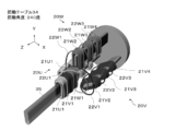
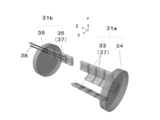
- the coil unit arrangement device 28 includes a control unit 29 and an arrangement unit 30.
- the array unit 30 is A holding portion 31a provided with a self-rotating coil unit support 33 for supporting the coil unit;
- a receiving portion 31b that includes an arrangement coil group support 35 that supports the arrangement coil group, and that rotates relative to the holding portion;
- a transport unit 31c for transporting the coils of the coil unit supported by the coil unit support 33 to the array coil group support 35; Is provided.
- the control unit 29 When forming an array coil group by taking out and arranging the coils from the coil unit based on the arrangement order, the connecting wire between the array coil group and the coil to be extracted is between the array coil group and another coil unit.
- the operations of the holding unit 31a, the receiving unit 31b, and the transport unit 31c are controlled so as to be arranged on the same side with respect to the crossover.
- the holding part 31a includes a coil unit support 33 having the required number of phases and a rotation table 34 to which the coil unit support 33 is connected. Each of the coil unit supports 33 can rotate.
- the receiving portion 31b is disposed to face the holding portion 31a, and includes an array coil group support 35 and a rotation table 36 to which the array coil group support 35 is connected. Similar to the holding part 31a, the array coil group support 35 can rotate. Further, the connection location between the array coil group support 35 and the rotary table 36 can be adjusted in the radial direction of the rotary table 36.
- the array coil group support body 35 and the coil unit support body 33 have a gap in the Z direction so that the crossover wires 22 can pass therethrough.
- the axial direction of rotation and rotation of the coil unit support 33, the array coil group support 35, and the rotation tables 34 and 36 is the Z direction. In the present embodiment, the Z direction substantially coincides with a center axis TT of a coil described later.
- the holding portion 31a and the receiving portion 31b are relatively rotated.
- the coil unit support 33 and the arrayed coil group support 35 of the holding portion 31a can rotate at an arbitrary rotation direction and rotation speed.
- the holding unit 31 a fixes the internal gear of the planetary gear, uses the rotation of the planetary gear carrier for rotation of the rotation table 34, and uses the rotation of the planetary gear for rotation of the coil unit support 33.
- 31a can be configured.
- the coil unit support 33 and the rotation table 34 may be driven by independent motors.
- the transport unit 31 c includes a plurality of claws 32 for gripping the coil, and at least one of the claws 32 can adjust a distance from the other claws 32.
- the transport unit 31c includes a mechanism that can move in two directions, the Y direction and the Z direction.
- the conveyance part 31c can hold
- sequence coil group support body 35 can be sent out to a Z direction as needed.
- the conveyance unit 31c may be configured by a multi-indirect robot.
- FIGS. 2 to 6 show a coil unit of an air-core coil and a molding process of the coil unit.
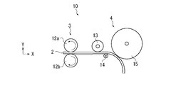
- the processing unit 10 includes a feeding unit 3 and a deforming unit 4.
- the feed unit 3 includes a drive roll 12a and a driven roll 12b disposed to face the drive roll 12a, and rotates the drive roll 12a while holding the coil wire 2 between the drive roll 12a and the drive roll 12b.
- the coil wire 2 is fed out from a supply unit (not shown) and conveyed to the deformation unit 4 while being shaped to be linear in the longitudinal direction.
- the deformation unit 4 includes a pressing roll 13, a support roll 14, and a pressing roll 15.
- the support roll 14 is arranged on one side of the conveyance path of the coil wire 2
- the push roll 15 is arranged on the other side of the conveyance path of the coil element 2 so as to move in a direction crossing the conveyance path. It has become.
- the coil wire 2 is deformed into a desired curvature by a pressing operation of pressing the coil wire 2 with the pressing roll 15.
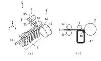
- the coil wire 2 that has passed through the deformable portion 4 becomes a molded body 17.
- a guide 16 As shown in FIG. 3, the coil wire 2 that has passed through the deformable portion 4 becomes a molded body 17.
- the molded body 17 progresses spirally in the Z-axis direction while being guided by the guide 16 (in the perspective view of FIG. 2, the spiral shape is emphasized and drawn).
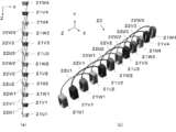
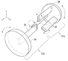
- processing is performed so that the molded body 17 forms a coil unit 20 in which a required number of coils 21 and crossover wires 22 are sequentially arranged.
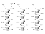
- the coil unit 20 includes four concentrated winding coils 21 and five crossovers 22.
- the coil 21 is a multilayer ⁇ -winding coil in which straight portions and curved portions are alternately formed.
- the connecting wire 22 of the coil unit is formed so as to go around the central axis TT of the coil 21.
- the connecting wire 22 is designed to have a length necessary for connecting the coils 21 having the same phase when the coil 21 is disposed in the motor.
- Desirable circulation of the crossover wire 22 with respect to the central axis TT depends on the symmetry of the inner peripheral shape of the coil 21. Specifically, when the coil 21 is approximately rectangular, the coil 21 is approximately square. In this case, it is an integral multiple of 1 ⁇ 4 round. Not only this but the circumference with respect to the central axis TT of the crossover wire 22 may be set arbitrarily.
- the coil unit 20 may be formed by normal bobbin winding, not limited to the multilayer ⁇ winding.
- the description will be made in the case of the coil unit 20 in which the connecting wire 22 is rotated 360 degrees around the central axis TT.
- the U-phase coil unit is 20U
- the coils are 21U1, 21U2, 21U3, 21U4, and the transitions between the coils in order from the bottom of the page.
- the lines are described as 22U1, 22U2, 22U3. V phase and W phase are described similarly.
- the connecting wires 22 at both ends of the coil unit is a connecting line to the power source, and the other is a connecting line to the neutral point. However, in order to make it easier to see in the subsequent drawings, the drawing of the connecting wires 22 at both ends of the coil unit is omitted.
- FIG. 7 shows an XY plan view of the holding portion 31a in the initial state viewed from the receiving portion 31b.
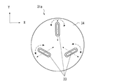
- the central axis of the coil unit support 33 is located at 0 o'clock, 4 o'clock, and 8 o'clock when the rotary table 34 is regarded as a clock, and is approximately 120 degrees apart. If the angle of the coil unit support 33 at the 0 o'clock position is 90 degrees, the coil unit support 33 is connected to the rotary table 34 at a relationship of 30 degrees at 4 o'clock and 150 degrees at 8 o'clock. As shown by a two-dot chain line arrow in FIG. 7, the connection location between the coil unit support 33 and the rotary table 34 can be adjusted in the radial direction of the rotary table 34.
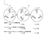
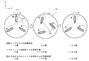
- FIG. 8 shows a change in the XY plan view when the holding portion 31a in operation from the receiving portion 31b is viewed in the Z direction.
- a ⁇ mark is written on the coil unit support 33.
- the coil unit support 33 rotates in the counterclockwise direction indicated by the alternate long and short dash line at the rotational speed ⁇ 2, and the rotation table 34 rotates at the rotational speed ⁇ 1 in the clockwise direction indicated by the broken line arrow.
- the rotary table 34 when the rotary table 34 is rotated 90 degrees, when attention is paid to the coil unit support 33 that was in the 0 o'clock position in the initial state, the coil unit support 33 moves to the 3 o'clock position. At this time, the ⁇ mark comes to the center side of the rotary table 34.
- the rotation table 34 is rotated 120 degrees, the coil unit support 33 that was at the 0 o'clock position in the initial state is at the 4 o'clock position. At this time, the angle coincides with the coil unit support 33 at the 4 o'clock position in the initial state.
- the rotating table 34 rotates once in the clockwise direction
- the coil unit support 33 rotates twice in the counterclockwise direction, but apparently the counterclockwise value obtained by subtracting one rotation of the revolution (the rotation of the rotating table 34). Rotate once around.
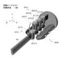
- FIG. 9 shows an initial state in which the coil units 20 for three phases are set on the coil unit support 33 of the holding portion 31a.
- the coil end on the Y axis + side in FIG. 5 is on the ⁇ mark side in FIG. 8, and the order of each phase is the position of 0:00 in the arrangement order when the rotary table 34 is rotated clockwise. It is installed so as to pass in the order of a certain U phase ⁇ V phase ⁇ W phase.
- the coil 21U1 of the coil unit 20U is gripped and transported by the transport unit 31c from the state of FIG.
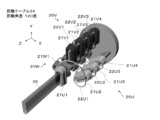
- the rotation table 34 is rotated 120 degrees clockwise to a position with a rotation angle of 120 degrees.
- the coil 21 ⁇ / b> V ⁇ b> 1 of the coil unit 20 ⁇ / b> V is fitted on the array coil group support 35 from the state of FIG. 11.
- the crossover 22U1 passes through the upper side of the coil 21V1 (the positive direction side of the Y axis) and connects the coil 21U1 and the coil 21U2.
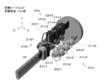
- FIG. 13 from the state of FIG.
- the rotation table 34 is further rotated 120 degrees clockwise to a rotation angle of 240 degrees.
- the coil 21 ⁇ / b> W ⁇ b> 1 of the coil unit 20 ⁇ / b> W is fitted on the array coil group support 35 from the state of FIG. 13. From FIG. 12, even when the rotation table 34 rotates 120 degrees, the crossover wire 22 ⁇ / b> U ⁇ b> 1 is connected to the coil 21 ⁇ / b> U ⁇ b> 2 via the + X side when viewed from the array coil group support 35.
- the rotation table 34 is further rotated 120 degrees clockwise to a rotation angle of 360 degrees.
- the coil 21 ⁇ / b> U ⁇ b> 1 fitted on the array coil group support 35 is placed in the Z direction from the state of FIG. 15, and the coil 21 ⁇ / b> U ⁇ b> 2 of the coil unit 20 ⁇ / b> U is fitted on the array coil group support 35.
- the connecting wire 22U1 is rotated by the rotation of the rotation table 34 of the holding portion 31a and the rotation of the coil unit support 33, and the -Z of the coil 21W1.
- Crossover 22U (n) is between crossover 22W (n-1) and crossover 22V (n)
- the crossover line 22V (n) is between the crossover line 22U (n) and the crossover line 22W (n)
- the crossover line 22W (n) is between the crossover line 22V (n) and the crossover line 22V (n + 1).
- the relative positional relationship between the central axes of the coil unit support 33 is constant.
- the structure of the apparatus can be simplified, and the main motion is a rotational motion, so that there is an advantage that it is easy to speed up the operation.
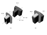
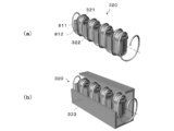
- FIG. 19 is a perspective view of a split stator core 811 that forms a stator of a motor having a rotor inside.
- the divided stator core 811 is formed by laminating electromagnetic steel plates formed by pressing or the like, and a part thereof is integrated by caulking or welding. Further, it is composed of a teeth portion 811 (a) and a yoke portion 811 (b) for arranging the coil 21, and as shown in FIG. 19 (b), before the coil 21 is arranged on the teeth portion 811 (a). Then, the insulating member 812 is fitted in advance.
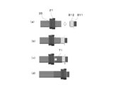
- FIG. 20 shows a schematic diagram of the fitting process.
- the split stator core 811 fitted with the insulating member 812 is brought into contact with the end surface of the array coil group support 35 that penetrates the air core portion of the array coil group 23, and the coil 21 of the array coil group 23 is split into the split stator. Fit into the core 811.
- the split stator core fitted with the coil 21 can be continuously subjected to the fitting process by sliding in the direction intersecting the axial direction of the arrayed coil group support 35 that supports the arrayed coil group 23.
- a detailed process of fitting the coil 21 to the split stator core 811 while focusing on one coil 21 is shown in FIG. From the initial state of FIG. 21A, as shown in FIG.
- the divided stator core 811 fitted with the insulating member 812 and the arrayed coil group support 35 that supports the arrayed coil group 23 are brought into contact with each other. Monkey. Thereafter, as shown in FIG. 21 (c), the guide tape 71 is wound so that the arrayed coil group support 35 and the divided stator core 811 are integrated, and at least part of the insulating member 812 is included.
- the coil 21 is fitted to the split stator core 811 as shown in FIG.
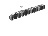
- a linear stator 810 as shown in FIG. 22 is obtained.
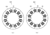
- the linear stator 810 obtained in the fitting step is arranged in an annular shape and fixed by baking bamelling or the like, thereby obtaining a stator as shown in FIG.
- FIG. 25 (a) is a cross-sectional view of the stator of FIG. 23, but the space factor is increased by alternately changing the cross section of the adjacent coil shape from coil 24 to coil 25 as shown in FIG. 25 (b). be able to.
- the coil unit to be arranged in another arrangement step 1 by the coil unit arrangement apparatus of the first embodiment has the same configuration as that of the first embodiment except that the number of turns of the central axis TT of the crossover is 1/2. It has. This is effective when the length of the crossover is short and it is difficult to make one turn with respect to the central axis TT.
- the conveyance part 31c is the same as that of 1st embodiment, description is abbreviate
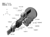
- FIG. 26 shows a coil unit 120 used in another arrangement step 1 by the coil unit arrangement apparatus of the first embodiment.
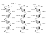
- the coil unit 120 includes four coils 121 and five connecting wires 122 that circulate around the central axis TT by a coil wire 2.
- the coil 121 prevents the coil 121 from spreading in the direction of the central axis TT and connects the coil portion 121 and the jumper wire 121 so that the coil wire 2 in the vicinity of the jumper wire 122 constituting the coil 121 is not deformed. Two places in the vicinity are restrained by the attachment tape P.
- the coils 121 before and after the crossover wire 122 are connected in a positional relationship that is rotated 180 degrees about the central axis TT. In this way, three coil units 120 are prepared. As shown in FIG.
- the three phases are the U phase, the V phase, and the W phase.
- the U-phase coil unit is 120U
- the coils are 121U1, 121U2, 121U3, 121U4,
- the lines are described as 122U1, 122U2, 122U3.
- V phase and W phase are described similarly.
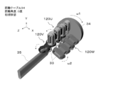
- FIG. 28 is a perspective view of the arrangement unit of the coil unit arrangement apparatus of the first embodiment.
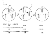
- FIG. 29 shows a change in the XY plan view of the holding portion 31a in operation from the receiving portion 31b in the Z direction.
- the central axis of the coil unit support 33 is located at 0 o'clock, 4 o'clock, and 8 o'clock when the rotary table 34 is regarded as a clock, and is approximately 120 degrees apart. ing.
- the rotation angle of the rotation table 34 is 0 degree, if the angle of the coil unit support 33 at the 0 o'clock position is 90 degrees, the rotation angle is 150 degrees at 4 o'clock and 30 degrees at 8 o'clock.
- the moving table 34 is connected.
- the coil unit support 33 rotates in the counterclockwise direction indicated by the alternate long and short dash line at the rotational speed ⁇ 2, and the rotation table 34 rotates at the rotational speed ⁇ 1 in the clockwise direction indicated by the broken line arrow.
- the rotary table 34 when the rotary table 34 is rotated 90 degrees, when attention is paid to the coil unit support 33 that was in the 0 o'clock position in the initial state, the coil unit support 33 moves to the 3 o'clock position. At this time, since the coil unit support 33 rotates -135 degrees, it apparently rotates -45 degrees counterclockwise.
- the rotation table 34 is rotated 120 degrees, the coil unit support 33 that was at the 0 o'clock position in the initial state is at the 4 o'clock position. At this time, the angle coincides with the coil unit support 33 at the 4 o'clock position in the initial state.
- the rotary table 34 makes one clockwise rotation, the coil unit support 33 rotates 3/2 counterclockwise. At this time, apparently, one rotation of revolution (rotation of the rotation table 34) is subtracted and the rotation is halved counterclockwise.
- FIG. 30 shows an initial state in which the three-phase coil units 120 are set on the coil unit support 33 of the holding portion 31a.
- the initial state of each coil unit 120 is as follows.
- the coil unit 120U is installed on the coil unit support 33 at the 0 o'clock position so that the coil end to which the connecting wire 122 of the coil 121U1 is connected is on the outer diameter side of the turntable 34.
- the coil unit 120V is installed on the coil unit support 33 at the 8 o'clock position so that the coil end to which the connecting wire 122 of the coil 121V1 is connected is on the center side of the rotary table 34.
- the coil unit 120W is installed on the coil unit support 33 at the 4 o'clock position so that the coil end to which the connecting wire 122 of the coil 121W1 is connected is on the outer diameter side of the rotary table 34.
- the coil 121U1 of the coil unit 120U is gripped and transported by the transport unit 31c from the initial state of FIG.
- the rotation table 34 is rotated 120 degrees clockwise to a position where the rotation angle is 120 degrees, and the coil 121V1 of the coil unit 120V is arranged as an array coil group support. 35.
- the connecting wire 122 is connected to the coil 121V1 of the coil unit 120V to be fitted to the array coil group support 35 and the coil 121U2 located at the tip of the coil unit support 33 at the 4 o'clock position.
- the coil end on the other side becomes the outer diameter side of the rotary table 34.
- the coil end on the side to which the connecting wire 122 is connected is the center side of the rotary table 34.
- the crossover wire 122U1 passes through the upper side of the coil 121V1 (the positive direction side of the Y axis) and connects the coil 121U1 and the coil 121U2.
- the rotation table 34 is further rotated 120 degrees clockwise to a position where the rotation angle is 240 degrees, and the coil 121W1 of the coil unit 120W is arranged in the array coil group. Fit onto the support 35.
- the connecting wire 122U1 is connected to the coil 121U2 via the back side (minus side in the Z direction) of the coil 121W1.
- the rotation table 34 is further rotated 120 degrees clockwise to a rotation angle of 360 degrees, and is fitted on the array coil group support 35.
- the coil 121U1 is fed in the Z direction, and the coil 121U2 of the coil unit 120U is fitted on the array coil group support 35.
- the connecting wire 122U1 is moved to the rear side of the coil 121W1 by the rotation of the rotation table 34 of the holding portion 31a and the rotation of the coil unit support 33 ( Passes through the gap between the coil unit support 33 and the arrayed coil group support 35 in the Z direction.
- the coil unit 120 Each time the rotation table 34 makes one rotation, the coil unit 120 apparently makes a half turn counterclockwise, so all the coils 121 fitted to the array coil group support 35 are in the same direction. Therefore, all the coils 121 are repeatedly fitted to the array coil group support 35 by repeating the above-described operation, so that the crossover wires 122 are not crossed and arranged in a line in the order in which they are arranged on the stator.
- the arranged array coil group 23 can be obtained.
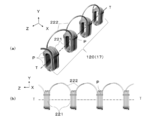
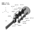
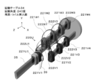
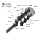
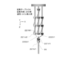
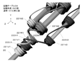
- FIG. 35 shows a coil unit 220 used in another arranging step 2 by the coil unit arranging apparatus of the first embodiment.
- the coil unit 220 In the coil unit 220, four coils 221 and five crossover wires 222 that make a half turn around the central axis TT are constituted by the coil wire 2.
- the coil 221 prevents the coil 221 from spreading in the direction of the central axis TT and connects the coil portion 221 and the jumper wire 221 so that the coil wire 2 in the vicinity of the jumper wire 222 constituting the coil 221 is not deformed. 3 places including 2 places in the vicinity are restrained by the attachment tape P.
- the coils 221 before and after the crossover 222 are connected in the same positional relationship with the central axis TT as an axis.
- the drawing of the attachment tape P is omitted for easy understanding.
- three coil units 220 are prepared.
- the three phases are the U phase, the V phase, and the W phase.
- the U phase coil unit is 220U, and the coils are 221U1, 221U2, 221U3, 221U4
- the lines are described as 222U1, 222U2, 222U3.
- V phase and W phase are described similarly.
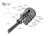
- FIG. 37 is a perspective view of the arrangement unit of the coil unit arrangement device of the first embodiment.
- FIG. 38 shows a change in the XY plan view of the holding unit 31a in another arrangement step 2 performed by the coil unit arrangement apparatus of the first embodiment during operation from the receiving unit 31b when viewed in the Z direction.
- the central axis of the coil unit support 33 is located at 0 o'clock, 4 o'clock, and 8 o'clock when the rotary table 34 is regarded as a clock, and is approximately 120 degrees apart. ing. Further, all the coil unit supports 33 are connected to the rotating table 34 at the same angle.
- the coil unit support 33 rotates in the counterclockwise direction indicated by the alternate long and short dash line at the rotational speed ⁇ 2, and the rotation table 34 rotates at the rotational speed ⁇ 1 in the clockwise direction indicated by the broken line arrow.
- the rotation table 34 When the rotation table 34 is rotated 120 degrees, the position of the coil unit support 33 at the 0 o'clock position in the initial state coincides with the position of the coil unit support 33 at the 4 o'clock position in the initial state. Become. When the rotating table 34 makes one clockwise rotation, the coil unit support 33 makes one counterclockwise rotation, so that the same orientation is maintained in appearance.
- FIG. 39 shows an initial state in which the coil units 220 for three phases are set on the coil unit support 33 of the holding portion 31a that moves in this manner.
- the initial state of each coil unit 220 is as follows.
- the coil unit 220U is installed on the coil unit support 33 at the 0 o'clock position so that the coil end to which the connecting wire 222 of the coil 221U1 is connected is on the outer diameter side of the rotary table 34.
- the coil unit 220V is installed on the coil unit support 33 at 8 o'clock and the coil unit 220W is installed at 4 o'clock so as to be in the same direction as the coil unit 220U.
- the coil 221U1 of the coil unit 220U is gripped and transported by the transport unit 31c and fitted onto the arrayed coil group support 35.
- the rotation table 34 is rotated 120 degrees clockwise to a position where the rotation angle is 120 degrees, and the coil 221V1 of the coil unit 220V is arranged as an array coil group support. 35.
- the crossover wire 222U1 passes through the upper side of the coil 221V1 (the positive direction side of the Y axis) and connects the coil 221U1 and the coil 221U2.
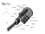
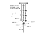
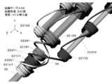
- the rotation table 34 is further rotated 120 degrees clockwise to a position where the rotation angle is 240 degrees, and the coil 221U1 and the coil are rotated using the restraining tool 39.
- the connecting wire 222U1 connecting 221U2 is restrained.
- the crossover wire 222U1 restrained by the restraining tool 39 goes around the plus side in the X direction with respect to the coil 221W1.
- FIG. 44 when the coil 221W1 is fitted to the array coil group support 35, the crossover wire 222U1 is connected to the coil 221U2 via the back side (minus side in the Z direction) of the coil 221W1.
- the crossover wire 222U1 is connected to the rotation table 34 of the holding portion 31a.
- the coil 221W1 passes through the back side (minus side in the Z direction), and further passes through the gap in the Z direction between the coil unit support 33 and the arrayed coil group support 35. .
- the arrangement similar to FIG. 18 is arranged in a line in the arrangement order on the stator without crossing the connecting wires 222.
- the coil group 23 can be obtained.
- FIG. 45 is a perspective view of the rotation table 34 before the rotation angle is 240 degrees and the coil 221W1 is inserted into the array coil group support 35.
- the coil unit arrangement device By using the coil unit arrangement device according to the present invention, handling is possible in a state where the connecting wire of the coil unit circulates around the central axis TT. Since it is not linear, the length in the Z-axis direction necessary for the holding portion 31a when obtaining the array coil group can be reduced. Even if the number of coils in the coil unit is increased, the rotation of the rotation table 34 of the holding unit 31a, the rotation of the coil unit support 33, and the coil at a specific position are gripped and transferred by the transfer unit 31c to arrange the coils. It can be a repetitive operation to fit the group support 35. Furthermore, the first embodiment can be implemented by a simple mechanism because of the rotational movement in which the central axes of the coil units do not move relative to each other. In the prior art, a gripping mechanism corresponding to the number of coils of the coil unit is necessary, and the number of coils to be gripped needs to be reduced as the process proceeds. Further, the central axis of the coil unit has to be moved relatively.
- the rotation rate of the coil unit support 33 is maintained with respect to one rotation of the rotation table 34 and the rotation table 36 relative to each other, even if the rotational speed ⁇ 1 of the coil unit support 33 varies. Good.
- the amount of winding of the coil unit with respect to the central axis of the connecting wire can be arbitrarily set in the molding process, but there may be a connecting wire with a different number of turns in the coil unit. This case can be dealt with by appropriately adjusting the amount of rotation of the carp unit support 33 that supports the coil unit in the arranging step.
- FIG. 48 shows a divided support used in the second embodiment.
- the divided support body 37 has a structure that can be continuously engaged with the other divided support bodies 37 and has at least one or more through holes.
- the coil unit support 33 and the array coil group support 35 are configured by combining the split support 37 as shown in FIG.
- the turntable 36 to which the array coil group support 35 is connected also has a through hole.
- the array coil group support 35 is set to face the coil unit support 33 at the 0 o'clock position when the holding portion 31a rotates.
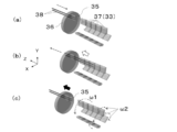
- the transport unit 31 c includes a guide bar 38 that penetrates the divided support 37 and the through hole of the rotary table 36.
- the retracted guide bar 38 moves in the direction of the solid line arrow, and the leading end of the coil unit support 33 is obtained.
- the split support 37 at the tip is moved in the direction of the white arrow while being guided by the guide bar 38 and connected to the array coil group support 35.
- the guide bar 38 is retracted in the direction of the solid line arrow so as not to hinder the rotation of the holding portion 31a.
- the rotation table 36 moves in the direction of the black arrow in FIG. 50C according to the interval between the arrayed coil group support 35 and the coil unit support 33 that faces next.
- the holding unit 31a may be moved in the ⁇ Z direction.
- the coil unit support body 33 and the arrangement
- FIG. 51 shows a coil unit 320 used in the third embodiment.
- the coil unit 320 four coils 321 and five connecting wires 322 that make one round of the central axis are constituted by the coil wire 2.
- the coil 321 is fitted to the split stator core 811 fitted with the insulating member 812 by applying a method similar to the fitting step of the first embodiment shown in FIG. 20 to the coil unit.
- the coil unit 320 having the split stator core can be rotated while being rotated, as in the first embodiment.
- the coil can be implemented so that the central axis of the coil intersects the longitudinal direction of the coil unit support 333.
- the cylindrical coil unit support 333 has an opening through which the claw 32 of the transport unit 31c passes so that the cross section of the coil unit support 333 can be used to send out or fix a predetermined coil 321. Is desirable.
- the coil unit 320 may be supported and rotated by a rod-shaped magnetic body by utilizing the fact that the material of the divided stator core is a ferromagnetic body. Thereby, even if it is the concentrated winding made by the normal bobbin winding, the same operation as the coil having the air core portion can be performed.
- a coil unit array device according to a fourth embodiment of the present invention will be described with reference to FIGS. 53 to 55.
- the fourth embodiment is different from the first embodiment in that the coil unit support is moved one by one. Differences from the first embodiment will be described.
- the three coil units 20 in FIG. 5 are used as the coil units.
- the tip end in the Z-axis direction supported by the coil unit support 33 is used.
- the case where the array coil group in which the coils 21 are arrayed in a predetermined array order is obtained by fitting the coil 21 on the side to the array coil group support 35 will be described.
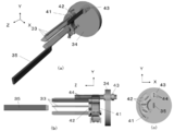
- FIG. 53 shows a perspective view, a YZ plan view, and an XY plan view of an arrangement portion used in the fourth embodiment.
- the holding body 41 is fixed to a base (not shown) and holds the coupling 42 to which the coil unit support 33 is connected.
- the holding body 41 matches the trajectory that passes through the holding body 41 of the coupling 42 and the trajectory that the rotating body 43 rotates as the rotating table 34 rotates. It is desirable to install so as to.
- the holding body 41 includes a retrograde prevention tool 411 in order to prevent the coupling 42 put in the holding body 41 from going backward.
- the retrograde prevention tool 411 rotates around a rotation shaft 414 that is supported by a bearing 413 fixed to the holder 41.
- the stopper 412 restricts the rotation of the retrograde prevention tool 411.
- the anti-reverse tool 411 does not prevent the coupling 42 from entering the holding body 41, but prevents it from going backward.
- the coupling 42 and the rotating body 43 are provided with two or more through-holes through which the connection bar 44 passes.
- the through bar 44 can reciprocate in the Z direction, and the through bar 44 passes through the coupling 42 and the rotating body 43 to rotate and rotate the coil unit support 33 connected to the coupling 42.
- the coupling 42 is desirably provided with a slit so as to be stably held by the holding body 41. In the subsequent drawings, drawing related to the retrograde preventer 411 is omitted.
- the coil unit support 33 In the initial state, as shown in FIG. 55 (a), the coil unit support 33 is held by the holding body 41 in a state of being adjacent to each other around the 9 o'clock position. As shown in FIG. 56 (a), the rotating table 34 is rotated and the rotating body 43 is rotated from the state shown in FIG. 55 (a), so that the coupling 42 and the rotating body 43 closer to the 0 o'clock position.
- the connection bar 44 is penetrated by matching the through holes.
- the coil unit support 33 rotates in the counterclockwise direction indicated by the alternate long and short dash line at the rotational speed ⁇ 2, and the rotation table 34 rotates at the rotational speed ⁇ 1 in the clockwise direction indicated by the broken line arrow.
- the coil is rotated by the rotation of the rotation table 34 and the rotation of the coil unit support 33 which are rotated through the through bar 44 from the state of FIG. 56 (a).
- the unit 20 rotates while rotating from 0 o'clock to 4 o'clock. Thereafter, the other coil unit 20 held by the holding body 41 is pushed up and rotated to the 8 o'clock position.
- 56 (b) is a YZ plan view of FIG. 55 (b)
- FIG. 56 (c) is a YZ plan view of FIG. 55 (c).
- 56D is an XY plan view of the rotating coil unit 20 when the other coil unit 20 is pushed up and rotated to the 8 o'clock position.
- the through bar 44 is moved in the -Z direction at the 8 o'clock position to release the connection with the rotary table 34.
- the turning table 34 is turned and the rotating body 43 is rotated so that the through hole of the rotating body 43 is aligned with the coupling 42 closer to 0:00.
- the coil units 20 are installed in the order of the U phase, the V phase, and the W phase from the coil unit support 33 closer to 0 o'clock.
- the coil unit support 33 is rotated one by one through the through bar 44. And rotate.
- the coil 21 on the tip side in the Z-axis direction supported by the coil unit support 33 is used as the array coil group support 35. An array coil group in which the coils 21 are arranged in a predetermined arrangement order is obtained.
- the coil unit support 33 to be rotated is one, handling of the crossover wire is facilitated. Therefore, even when the number of phases of the motor is large, the array coil group can be obtained with certainty.
Landscapes
- Engineering & Computer Science (AREA)
- Power Engineering (AREA)
- Manufacturing & Machinery (AREA)
- Manufacture Of Motors, Generators (AREA)
- Windings For Motors And Generators (AREA)
Abstract
Dispositif d'agencement d'unités de bobine qui forme un groupe de bobines agencées par l'agencement, dans un ordre d'agencement prescrit, de chacune des bobines d'unités de bobines dans lesquelles de multiples bobines correspondant à de multiples phases sont connectées à l'aide d'un fil de liaison pour chaque phase, ledit dispositif d'agencement d'unités de bobines étant conçu de manière à être équipé : d'une partie de retenue équipée de corps de support d'unités de bobines rotatifs qui supportent les unités de bobines ; et d'une partie de réception, qui est équipée d'un corps de support de groupe de bobines agencées qui supporte le groupe de bobines agencées, et tourne par rapport à la partie de retenue.
Priority Applications (3)
| Application Number | Priority Date | Filing Date | Title |
|---|---|---|---|
| US15/741,644 US10693355B2 (en) | 2015-07-06 | 2016-06-29 | Coil unit arrangement device |
| EP16821288.4A EP3322072B1 (fr) | 2015-07-06 | 2016-06-29 | Dispositif d'agencement d'unités de bobines |
| CN201680033197.6A CN107636942B (zh) | 2015-07-06 | 2016-06-29 | 线圈单元排列装置 |
Applications Claiming Priority (2)
| Application Number | Priority Date | Filing Date | Title |
|---|---|---|---|
| JP2015-134883 | 2015-07-06 | ||
| JP2015134883A JP5942236B1 (ja) | 2015-07-06 | 2015-07-06 | コイルユニット配列装置 |
Publications (1)
| Publication Number | Publication Date |
|---|---|
| WO2017006819A1 true WO2017006819A1 (fr) | 2017-01-12 |
Family
ID=56244713
Family Applications (1)
| Application Number | Title | Priority Date | Filing Date |
|---|---|---|---|
| PCT/JP2016/069233 Ceased WO2017006819A1 (fr) | 2015-07-06 | 2016-06-29 | Dispositif d'agencement d'unités de bobines |
Country Status (5)
| Country | Link |
|---|---|
| US (1) | US10693355B2 (fr) |
| EP (1) | EP3322072B1 (fr) |
| JP (1) | JP5942236B1 (fr) |
| CN (1) | CN107636942B (fr) |
| WO (1) | WO2017006819A1 (fr) |
Families Citing this family (5)
| Publication number | Priority date | Publication date | Assignee | Title |
|---|---|---|---|---|
| JP6811042B2 (ja) * | 2016-07-12 | 2021-01-13 | 日本電産コパル電子株式会社 | コアレスコイル及びこのコアレスコイルの製造方法 |
| JP6992554B2 (ja) * | 2018-02-01 | 2022-01-13 | トヨタ自動車株式会社 | コイル組付装置 |
| JP2020155430A (ja) * | 2019-03-18 | 2020-09-24 | Nittoku株式会社 | コイル巻線装置及びコイル巻線方法 |
| JP2020161215A (ja) * | 2019-03-25 | 2020-10-01 | Nittoku株式会社 | コイル巻線装置及びコイル巻線方法 |
| CN113078784B (zh) * | 2021-03-29 | 2022-04-19 | 江苏铭纳阳智能装备有限公司 | 一种新能源电机线圈扩口机构 |
Citations (2)
| Publication number | Priority date | Publication date | Assignee | Title |
|---|---|---|---|---|
| JP2010213467A (ja) * | 2009-03-11 | 2010-09-24 | Nissan Motor Co Ltd | コイル形成挿入装置 |
| JP2011259537A (ja) * | 2010-06-07 | 2011-12-22 | Hitachi Ltd | 回転電機とその製造方法 |
Family Cites Families (8)
| Publication number | Priority date | Publication date | Assignee | Title |
|---|---|---|---|---|
| JPS6015937B2 (ja) | 1976-07-02 | 1985-04-23 | 松下電器産業株式会社 | 光応答性高分子膜 |
| US7243874B2 (en) * | 2003-05-22 | 2007-07-17 | Atop S.P.A. | Apparatus and methods for winding wire coils for dynamo-electric machine components |
| JP4604071B2 (ja) * | 2007-09-11 | 2010-12-22 | スミダ電機株式会社 | コイル、スロットレスモータ及びコイルの製造方法 |
| JP5304058B2 (ja) * | 2008-07-03 | 2013-10-02 | トヨタ自動車株式会社 | 集中巻線式ステータの製造方法、及び集中巻線式ステータ |
| JP5204627B2 (ja) * | 2008-11-12 | 2013-06-05 | 日特エンジニアリング株式会社 | 連結コイル巻線方法および連結コイル巻線装置 |
| JP2012019575A (ja) * | 2010-07-06 | 2012-01-26 | Honda Motor Co Ltd | 電動機の突極集中巻きステータの製造方法 |
| JP5481307B2 (ja) * | 2010-08-02 | 2014-04-23 | 本田技研工業株式会社 | 電動機の突極集中巻きステータ |
| JP5768305B1 (ja) * | 2014-09-19 | 2015-08-26 | 福井県 | 固定子の製造方法および装置 |
-
2015
- 2015-07-06 JP JP2015134883A patent/JP5942236B1/ja active Active
-
2016
- 2016-06-29 CN CN201680033197.6A patent/CN107636942B/zh active Active
- 2016-06-29 US US15/741,644 patent/US10693355B2/en active Active
- 2016-06-29 WO PCT/JP2016/069233 patent/WO2017006819A1/fr not_active Ceased
- 2016-06-29 EP EP16821288.4A patent/EP3322072B1/fr active Active
Patent Citations (2)
| Publication number | Priority date | Publication date | Assignee | Title |
|---|---|---|---|---|
| JP2010213467A (ja) * | 2009-03-11 | 2010-09-24 | Nissan Motor Co Ltd | コイル形成挿入装置 |
| JP2011259537A (ja) * | 2010-06-07 | 2011-12-22 | Hitachi Ltd | 回転電機とその製造方法 |
Also Published As
| Publication number | Publication date |
|---|---|
| EP3322072A1 (fr) | 2018-05-16 |
| EP3322072A4 (fr) | 2018-06-06 |
| CN107636942A (zh) | 2018-01-26 |
| JP2017017935A (ja) | 2017-01-19 |
| US20180212498A1 (en) | 2018-07-26 |
| US10693355B2 (en) | 2020-06-23 |
| JP5942236B1 (ja) | 2016-06-29 |
| EP3322072B1 (fr) | 2021-02-24 |
| CN107636942B (zh) | 2020-05-12 |
Similar Documents
| Publication | Publication Date | Title |
|---|---|---|
| JP5942236B1 (ja) | コイルユニット配列装置 | |
| US8281481B2 (en) | Method for loading stator windings into a stator core | |
| EP3142235A1 (fr) | Procédé de fabrication de stator et stator | |
| CN102104301A (zh) | 线圈的制造装置 | |
| CN111434014A (zh) | 用于自动化制造电机的定子的方法和设备 | |
| JP5768305B1 (ja) | 固定子の製造方法および装置 | |
| EP2937978B1 (fr) | Procédé de fabrication de stator pour machine électrique tournante | |
| EP2955819A1 (fr) | Procédé de production de stator pour machines électriques tournantes | |
| US8151447B2 (en) | Apparatus for loading stator windings into a stator core | |
| US10027209B2 (en) | Method for manufacturing a stator for a rotating electrical machine | |
| US11165319B2 (en) | Method of forming a stator having skewed slots | |
| JP2008172863A (ja) | 回転電機及びその製造方法 | |
| JP7831256B2 (ja) | 巻線整形装置および巻線整形方法 | |
| US6343762B1 (en) | Winders for electric motor armatures | |
| JP7710544B2 (ja) | 製造装置及び製造方法 | |
| JP6996433B2 (ja) | ステータの製造装置及び製造方法 | |
| JP2019161770A (ja) | 巻線製造装置 |
Legal Events
| Date | Code | Title | Description |
|---|---|---|---|
| 121 | Ep: the epo has been informed by wipo that ep was designated in this application |
Ref document number: 16821288 Country of ref document: EP Kind code of ref document: A1 |
|
| WWE | Wipo information: entry into national phase |
Ref document number: 15741644 Country of ref document: US |
|
| NENP | Non-entry into the national phase |
Ref country code: DE |
|
| WWE | Wipo information: entry into national phase |
Ref document number: 2016821288 Country of ref document: EP |