WO2017006865A1 - Structure de palier et surcompresseur - Google Patents
Structure de palier et surcompresseur Download PDFInfo
- Publication number
- WO2017006865A1 WO2017006865A1 PCT/JP2016/069665 JP2016069665W WO2017006865A1 WO 2017006865 A1 WO2017006865 A1 WO 2017006865A1 JP 2016069665 W JP2016069665 W JP 2016069665W WO 2017006865 A1 WO2017006865 A1 WO 2017006865A1
- Authority
- WO
- WIPO (PCT)
- Prior art keywords
- bearing
- outer ring
- shaft
- housing
- bearing structure
- Prior art date
- Legal status (The legal status is an assumption and is not a legal conclusion. Google has not performed a legal analysis and makes no representation as to the accuracy of the status listed.)
- Ceased
Links
Images


Classifications
-
- F—MECHANICAL ENGINEERING; LIGHTING; HEATING; WEAPONS; BLASTING
- F01—MACHINES OR ENGINES IN GENERAL; ENGINE PLANTS IN GENERAL; STEAM ENGINES
- F01D—NON-POSITIVE DISPLACEMENT MACHINES OR ENGINES, e.g. STEAM TURBINES
- F01D25/00—Component parts, details, or accessories, not provided for in, or of interest apart from, other groups
- F01D25/16—Arrangement of bearings; Supporting or mounting bearings in casings
-
- F—MECHANICAL ENGINEERING; LIGHTING; HEATING; WEAPONS; BLASTING
- F01—MACHINES OR ENGINES IN GENERAL; ENGINE PLANTS IN GENERAL; STEAM ENGINES
- F01D—NON-POSITIVE DISPLACEMENT MACHINES OR ENGINES, e.g. STEAM TURBINES
- F01D25/00—Component parts, details, or accessories, not provided for in, or of interest apart from, other groups
- F01D25/18—Lubricating arrangements
-
- F—MECHANICAL ENGINEERING; LIGHTING; HEATING; WEAPONS; BLASTING
- F02—COMBUSTION ENGINES; HOT-GAS OR COMBUSTION-PRODUCT ENGINE PLANTS
- F02B—INTERNAL-COMBUSTION PISTON ENGINES; COMBUSTION ENGINES IN GENERAL
- F02B39/00—Component parts, details, or accessories relating to, driven charging or scavenging pumps, not provided for in groups F02B33/00 - F02B37/00
-
- F—MECHANICAL ENGINEERING; LIGHTING; HEATING; WEAPONS; BLASTING
- F02—COMBUSTION ENGINES; HOT-GAS OR COMBUSTION-PRODUCT ENGINE PLANTS
- F02B—INTERNAL-COMBUSTION PISTON ENGINES; COMBUSTION ENGINES IN GENERAL
- F02B39/00—Component parts, details, or accessories relating to, driven charging or scavenging pumps, not provided for in groups F02B33/00 - F02B37/00
- F02B39/14—Lubrication of pumps; Safety measures therefor
-
- F—MECHANICAL ENGINEERING; LIGHTING; HEATING; WEAPONS; BLASTING
- F16—ENGINEERING ELEMENTS AND UNITS; GENERAL MEASURES FOR PRODUCING AND MAINTAINING EFFECTIVE FUNCTIONING OF MACHINES OR INSTALLATIONS; THERMAL INSULATION IN GENERAL
- F16C—SHAFTS; FLEXIBLE SHAFTS; ELEMENTS OR CRANKSHAFT MECHANISMS; ROTARY BODIES OTHER THAN GEARING ELEMENTS; BEARINGS
- F16C19/00—Bearings with rolling contact, for exclusively rotary movement
- F16C19/02—Bearings with rolling contact, for exclusively rotary movement with bearing balls essentially of the same size in one or more circular rows
- F16C19/14—Bearings with rolling contact, for exclusively rotary movement with bearing balls essentially of the same size in one or more circular rows for both radial and axial load
- F16C19/18—Bearings with rolling contact, for exclusively rotary movement with bearing balls essentially of the same size in one or more circular rows for both radial and axial load with two or more rows of balls
- F16C19/181—Bearings with rolling contact, for exclusively rotary movement with bearing balls essentially of the same size in one or more circular rows for both radial and axial load with two or more rows of balls with angular contact
- F16C19/183—Bearings with rolling contact, for exclusively rotary movement with bearing balls essentially of the same size in one or more circular rows for both radial and axial load with two or more rows of balls with angular contact with two rows at opposite angles
- F16C19/184—Bearings with rolling contact, for exclusively rotary movement with bearing balls essentially of the same size in one or more circular rows for both radial and axial load with two or more rows of balls with angular contact with two rows at opposite angles in O-arrangement
-
- F—MECHANICAL ENGINEERING; LIGHTING; HEATING; WEAPONS; BLASTING
- F16—ENGINEERING ELEMENTS AND UNITS; GENERAL MEASURES FOR PRODUCING AND MAINTAINING EFFECTIVE FUNCTIONING OF MACHINES OR INSTALLATIONS; THERMAL INSULATION IN GENERAL
- F16C—SHAFTS; FLEXIBLE SHAFTS; ELEMENTS OR CRANKSHAFT MECHANISMS; ROTARY BODIES OTHER THAN GEARING ELEMENTS; BEARINGS
- F16C19/00—Bearings with rolling contact, for exclusively rotary movement
- F16C19/54—Systems consisting of a plurality of bearings with rolling friction
- F16C19/546—Systems with spaced apart rolling bearings including at least one angular contact bearing
- F16C19/547—Systems with spaced apart rolling bearings including at least one angular contact bearing with two angular contact rolling bearings
- F16C19/548—Systems with spaced apart rolling bearings including at least one angular contact bearing with two angular contact rolling bearings in O-arrangement
-
- F—MECHANICAL ENGINEERING; LIGHTING; HEATING; WEAPONS; BLASTING
- F16—ENGINEERING ELEMENTS AND UNITS; GENERAL MEASURES FOR PRODUCING AND MAINTAINING EFFECTIVE FUNCTIONING OF MACHINES OR INSTALLATIONS; THERMAL INSULATION IN GENERAL
- F16C—SHAFTS; FLEXIBLE SHAFTS; ELEMENTS OR CRANKSHAFT MECHANISMS; ROTARY BODIES OTHER THAN GEARING ELEMENTS; BEARINGS
- F16C27/00—Elastic or yielding bearings or bearing supports, for exclusively rotary movement
- F16C27/04—Ball or roller bearings, e.g. with resilient rolling bodies
- F16C27/045—Ball or roller bearings, e.g. with resilient rolling bodies with a fluid film, e.g. squeeze film damping
-
- F—MECHANICAL ENGINEERING; LIGHTING; HEATING; WEAPONS; BLASTING
- F16—ENGINEERING ELEMENTS AND UNITS; GENERAL MEASURES FOR PRODUCING AND MAINTAINING EFFECTIVE FUNCTIONING OF MACHINES OR INSTALLATIONS; THERMAL INSULATION IN GENERAL
- F16C—SHAFTS; FLEXIBLE SHAFTS; ELEMENTS OR CRANKSHAFT MECHANISMS; ROTARY BODIES OTHER THAN GEARING ELEMENTS; BEARINGS
- F16C33/00—Parts of bearings; Special methods for making bearings or parts thereof
- F16C33/30—Parts of ball or roller bearings
- F16C33/58—Raceways; Race rings
- F16C33/583—Details of specific parts of races
- F16C33/586—Details of specific parts of races outside the space between the races, e.g. end faces or bore of inner ring
-
- F—MECHANICAL ENGINEERING; LIGHTING; HEATING; WEAPONS; BLASTING
- F16—ENGINEERING ELEMENTS AND UNITS; GENERAL MEASURES FOR PRODUCING AND MAINTAINING EFFECTIVE FUNCTIONING OF MACHINES OR INSTALLATIONS; THERMAL INSULATION IN GENERAL
- F16C—SHAFTS; FLEXIBLE SHAFTS; ELEMENTS OR CRANKSHAFT MECHANISMS; ROTARY BODIES OTHER THAN GEARING ELEMENTS; BEARINGS
- F16C33/00—Parts of bearings; Special methods for making bearings or parts thereof
- F16C33/30—Parts of ball or roller bearings
- F16C33/66—Special parts or details in view of lubrication
- F16C33/6637—Special parts or details in view of lubrication with liquid lubricant
- F16C33/6685—Details of collecting or draining, e.g. returning the liquid to a sump
-
- F—MECHANICAL ENGINEERING; LIGHTING; HEATING; WEAPONS; BLASTING
- F05—INDEXING SCHEMES RELATING TO ENGINES OR PUMPS IN VARIOUS SUBCLASSES OF CLASSES F01-F04
- F05D—INDEXING SCHEME FOR ASPECTS RELATING TO NON-POSITIVE-DISPLACEMENT MACHINES OR ENGINES, GAS-TURBINES OR JET-PROPULSION PLANTS
- F05D2220/00—Application
- F05D2220/40—Application in turbochargers
-
- F—MECHANICAL ENGINEERING; LIGHTING; HEATING; WEAPONS; BLASTING
- F05—INDEXING SCHEMES RELATING TO ENGINES OR PUMPS IN VARIOUS SUBCLASSES OF CLASSES F01-F04
- F05D—INDEXING SCHEME FOR ASPECTS RELATING TO NON-POSITIVE-DISPLACEMENT MACHINES OR ENGINES, GAS-TURBINES OR JET-PROPULSION PLANTS
- F05D2240/00—Components
- F05D2240/50—Bearings
-
- F—MECHANICAL ENGINEERING; LIGHTING; HEATING; WEAPONS; BLASTING
- F05—INDEXING SCHEMES RELATING TO ENGINES OR PUMPS IN VARIOUS SUBCLASSES OF CLASSES F01-F04
- F05D—INDEXING SCHEME FOR ASPECTS RELATING TO NON-POSITIVE-DISPLACEMENT MACHINES OR ENGINES, GAS-TURBINES OR JET-PROPULSION PLANTS
- F05D2260/00—Function
- F05D2260/98—Lubrication
-
- F—MECHANICAL ENGINEERING; LIGHTING; HEATING; WEAPONS; BLASTING
- F16—ENGINEERING ELEMENTS AND UNITS; GENERAL MEASURES FOR PRODUCING AND MAINTAINING EFFECTIVE FUNCTIONING OF MACHINES OR INSTALLATIONS; THERMAL INSULATION IN GENERAL
- F16C—SHAFTS; FLEXIBLE SHAFTS; ELEMENTS OR CRANKSHAFT MECHANISMS; ROTARY BODIES OTHER THAN GEARING ELEMENTS; BEARINGS
- F16C19/00—Bearings with rolling contact, for exclusively rotary movement
- F16C19/02—Bearings with rolling contact, for exclusively rotary movement with bearing balls essentially of the same size in one or more circular rows
- F16C19/14—Bearings with rolling contact, for exclusively rotary movement with bearing balls essentially of the same size in one or more circular rows for both radial and axial load
- F16C19/16—Bearings with rolling contact, for exclusively rotary movement with bearing balls essentially of the same size in one or more circular rows for both radial and axial load with a single row of balls
- F16C19/163—Bearings with rolling contact, for exclusively rotary movement with bearing balls essentially of the same size in one or more circular rows for both radial and axial load with a single row of balls with angular contact
-
- F—MECHANICAL ENGINEERING; LIGHTING; HEATING; WEAPONS; BLASTING
- F16—ENGINEERING ELEMENTS AND UNITS; GENERAL MEASURES FOR PRODUCING AND MAINTAINING EFFECTIVE FUNCTIONING OF MACHINES OR INSTALLATIONS; THERMAL INSULATION IN GENERAL
- F16C—SHAFTS; FLEXIBLE SHAFTS; ELEMENTS OR CRANKSHAFT MECHANISMS; ROTARY BODIES OTHER THAN GEARING ELEMENTS; BEARINGS
- F16C2360/00—Engines or pumps
- F16C2360/23—Gas turbine engines
- F16C2360/24—Turbochargers
-
- F—MECHANICAL ENGINEERING; LIGHTING; HEATING; WEAPONS; BLASTING
- F16—ENGINEERING ELEMENTS AND UNITS; GENERAL MEASURES FOR PRODUCING AND MAINTAINING EFFECTIVE FUNCTIONING OF MACHINES OR INSTALLATIONS; THERMAL INSULATION IN GENERAL
- F16C—SHAFTS; FLEXIBLE SHAFTS; ELEMENTS OR CRANKSHAFT MECHANISMS; ROTARY BODIES OTHER THAN GEARING ELEMENTS; BEARINGS
- F16C33/00—Parts of bearings; Special methods for making bearings or parts thereof
- F16C33/30—Parts of ball or roller bearings
- F16C33/66—Special parts or details in view of lubrication
- F16C33/6637—Special parts or details in view of lubrication with liquid lubricant
- F16C33/6681—Details of distribution or circulation inside the bearing, e.g. grooves on the cage or passages in the rolling elements
-
- F—MECHANICAL ENGINEERING; LIGHTING; HEATING; WEAPONS; BLASTING
- F16—ENGINEERING ELEMENTS AND UNITS; GENERAL MEASURES FOR PRODUCING AND MAINTAINING EFFECTIVE FUNCTIONING OF MACHINES OR INSTALLATIONS; THERMAL INSULATION IN GENERAL
- F16C—SHAFTS; FLEXIBLE SHAFTS; ELEMENTS OR CRANKSHAFT MECHANISMS; ROTARY BODIES OTHER THAN GEARING ELEMENTS; BEARINGS
- F16C35/00—Rigid support of bearing units; Housings, e.g. caps, covers
- F16C35/04—Rigid support of bearing units; Housings, e.g. caps, covers in the case of ball or roller bearings
- F16C35/06—Mounting or dismounting of ball or roller bearings; Fixing them onto shaft or in housing
- F16C35/067—Fixing them in a housing
Definitions
- the present disclosure relates to a bearing structure that supports a shaft and a supercharger.
- a turbocharger in which a shaft is rotatably supported by a bearing housing is known.
- a turbine impeller is provided at one end of the shaft, and a compressor impeller is provided at the other end.
- the supercharger is connected to the engine, and the turbine impeller is rotated by exhaust gas discharged from the engine. The rotation of the turbine impeller causes the compressor impeller to rotate through the shaft.
- the supercharger compresses air and sends it to the engine as the compressor impeller rotates.
- an annular case portion is disposed in a bearing hole formed in a housing.
- a pair of ball bearings is assembled inside the case portion.
- the outer peripheral surface of a case part functions as a damper part which suppresses the vibration of a shaft with the lubricating oil supplied between bearing holes.
- the shaft can be supported while suppressing the vibration of the shaft.
- the cost required for processing and assembling the case portion is increased.
- An object of the present disclosure is to provide a bearing structure and a supercharger that can realize both functions of shaft vibration suppression and shaft support at low cost.
- a bearing structure is arranged in a bearing hole formed in a housing of a turbocharger, and has a ball bearing having an outer ring having a damper portion formed on an outer peripheral surface, and is fixed to the housing.
- the opposing member facing the axial direction of the shaft, the outer ring and the opposing member are formed on one side, the protruding part protruding to the other side, the outer ring and the opposing member are formed on the other side, And a restricting portion facing the rotation direction.
- the damper portion may include a protrusion that protrudes in the radial direction of the shaft from the outer peripheral surface of the outer ring and extends in the rotational direction.
- the ball bearing is an angular bearing, and the opposing member is opposed to the thick side end face, which is the end face of the outer ring in the axial direction, which is thicker in the radial direction of the shaft.
- a protruding portion or a restricting portion may be formed.
- Two ball bearings are provided in the bearing hole so as to be separated from each other in the axial direction, and the opposing member is disposed between the two ball bearings, and may be a spacer that restricts the movement of the two ball bearings in the proximity direction. Good.
- a fixed groove extending in the rotation direction is formed in the bearing hole, and the opposing member has an arc-shaped main body portion, and the outer peripheral surface of the main body portion is fitted into the fixed groove, and is formed at both ends of the main body portion in the circumferential direction.
- a restricting portion may be formed.
- An oil groove may be formed on one or both of the outer ring and the opposing member.
- the turbocharger includes the above bearing structure.
- both functions of shaft vibration suppression and shaft support can be realized at low cost.
- FIG. 1 is a schematic sectional view of the supercharger C.
- the supercharger C includes a supercharger main body 1.
- the supercharger main body 1 includes a bearing housing 2 (housing).
- a turbine housing 4 connected by a fastening mechanism 3 is connected to the left side of the bearing housing 2.
- a compressor housing 6 is connected to the right side of the bearing housing 2 by fastening bolts 5.
- the bearing housing 2, the turbine housing 4, and the compressor housing 6 are integrated.
- a projection 2 a protruding in the radial direction of the bearing housing 2 is provided on the outer peripheral surface of the bearing housing 2 in the vicinity of the turbine housing 4. Further, a protrusion 4 a that protrudes in the radial direction of the turbine housing 4 is provided on the outer peripheral surface of the turbine housing 4 in the vicinity of the bearing housing 2.
- the bearing housing 2 and the turbine housing 4 are fixed by fastening the protrusions 2 a and 4 a with the fastening mechanism 3.
- the fastening mechanism 3 is configured by, for example, a G coupling that holds the protrusions 2a and 4a.
- the bearing housing 2 is formed with a bearing hole 2b that penetrates the supercharger C in the left-right direction.
- a ball bearing 7 is provided in the bearing hole 2b.
- a shaft 8 is rotatably supported by the ball bearing 7.
- a turbine impeller 9 is integrally fixed to the left end portion of the shaft 8.
- the turbine impeller 9 is rotatably accommodated in the turbine housing 4.
- a compressor impeller 10 is integrally fixed to the right end portion of the shaft 8.
- the compressor impeller 10 is rotatably accommodated in the compressor housing 6.
- the compressor housing 6 is formed with an intake port 11 that opens to the right side of the supercharger C.
- the intake port 11 is connected to an air cleaner (not shown).
- a diffuser flow path 12 that pressurizes air is formed by the facing surfaces of the bearing housing 2 and the compressor housing 6.
- the diffuser channel 12 is formed in an annular shape from the radially inner side to the outer side of the shaft 8.
- the diffuser flow path 12 communicates with the intake port 11 via the compressor impeller 10 on the radially inner side.
- the compressor housing 6 is provided with an annular compressor scroll passage 13 that is located on the radially outer side of the shaft 8 with respect to the diffuser passage 12.
- the compressor scroll passage 13 communicates with an intake port of an engine (not shown) and the diffuser passage 12.
- the turbine housing 4 is formed with a discharge port 14 that opens to the left of the supercharger C.
- the discharge port 14 is connected to an exhaust gas purification device (not shown).
- a flow path 15 is provided in the turbine housing 4.
- the turbine housing 4 is provided with an annular turbine scroll passage 16 that is located on the radially outer side of the turbine impeller 9 with respect to the passage 15.
- the turbine scroll passage 16 communicates with a gas inlet (not shown) through which exhaust gas discharged from an exhaust manifold (not shown) is guided.
- the turbine scroll flow path 16 communicates with the flow path 15. Therefore, the exhaust gas guided from the gas inlet to the turbine scroll passage 16 is guided to the discharge port 14 via the passage 15 and the turbine impeller 9. The exhaust gas rotates the turbine impeller 9 in the flow process.
- Rotational force of the turbine impeller 9 is transmitted to the compressor impeller 10 through the shaft 8.
- the compressor impeller 10 rotates, the air is boosted and guided to the intake port of the engine as described above.
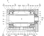
- FIG. 2 is a diagram in which a one-dot chain line portion of FIG. 1 is extracted.
- the supercharger C has a bearing structure S.
- the ball bearing 7 is disposed in the bearing hole 2b as described above.
- the shaft 8 is pivotally supported by a ball bearing 7.
- Two ball bearings 7 are disposed in the bearing hole 2b so as to be separated from each other in the axial direction of the shaft 8 (hereinafter simply referred to as the axial direction).
- the left side (turbine impeller 9 side) ball bearing 7 in FIG. 2 the right side (compressor impeller 10 side) ball bearing 7 is referred to as a compressor side bearing 21.
- a plurality of rolling elements 7c are arranged between the outer ring 7a and the inner ring 7b.
- the plurality of rolling elements 7c are in approximate contact with each of the outer ring 7a and the inner ring 7b.
- the cage 7d maintains a predetermined width in the circumferential direction of the inner ring 7b of the plurality of rolling elements 7c.
- the ball bearing 7 is, for example, an angular bearing. Connections connecting the contact points of the outer ring 7a and the rolling element 7c and the contact points of the rolling element 7c and the inner ring 7b (shown by broken lines in FIG. 2) are inclined with respect to the surface direction perpendicular to the axial direction of the shaft 8. (With contact angle).
- the ball bearing 7 can receive a thrust load in addition to the radial load of the shaft 8.
- a thrust load acting on the right side in FIG. 2 with respect to the shaft 8 is received by the turbine-side bearing 20. Further, a thrust load acting on the left side in FIG. 2 with respect to the shaft 8 is received by the compressor-side bearing 21.
- the outer ring 7a has different wall thicknesses (thicknesses in the radial direction of the shaft 8) at both end faces in the axial direction.
- the end surfaces (hereinafter referred to simply as the proximity direction) of the two ball bearings 7 are more than the opposite end surface 7g.
- the wall thickness is large.
- the inner ring 7b also has different wall thickness at both axial end surfaces.
- the end face 7h in the proximity direction is thinner than the end face 7i on the opposite side.
- annular protrusions 7e are formed on the outer peripheral surface of the ball bearing 7 (outer ring 7a) so as to be separated in the axial direction.
- the annular protrusion 7e protrudes in the radial direction of the shaft 8 on the outer peripheral surface of the outer ring 7a.
- the annular protrusion 7e extends in an annular shape over the entire circumference of the outer peripheral surface of the outer ring 7a.
- the two annular protrusions 7e are separated from the inner peripheral surface 2c of the bearing hole 2b.
- An oil hole 2d is opened in a portion of the inner peripheral surface 2c of the bearing hole 2b facing the two annular protrusions 7e.
- the oil hole 2d is located vertically above the shaft 8 (upper side in FIG. 2).
- the oil hole 2 d communicates with the outside of the bearing housing 2.
- Lubricating oil sent from an oil pump (not shown) is supplied from the oil hole 2d to the bearing hole 2b.
- the ball bearing 7 is lubricated by the lubricating oil supplied to the bearing hole 2b.
- the shaft 8 has a large-diameter portion 8a formed in a portion located on the left side in FIG. 2 in the bearing hole 2b.
- the outer diameter of the large diameter portion 8 a is larger than the inner diameter of the end surface 7 i of the inner ring 7 b of the turbine side bearing 20 and smaller than the outer diameter.
- the inner ring 7b of the turbine side bearing 20 is positioned by the large diameter portion 8a.
- an oil draining member 22 is fixed to the shaft 8 at a portion located on the right side in FIG. 2 in the bearing hole 2b.
- the oil draining member 22 suppresses leakage of the lubricating oil to the compressor impeller 10 side by scattering the lubricating oil after lubricating the compressor side bearing 21 radially outward.
- the outer diameter of the left end surface 22 a in FIG. 2 is larger than the inner diameter of the end surface 7 i of the inner ring 7 b of the compressor-side bearing 21 and smaller than the outer diameter. That is, the inner ring 7 b of the compressor side bearing 21 contacts the oil draining member 22.
- the inner diameter side spacer 23 is an annular member.
- the inner diameter side spacer 23 is provided between the two ball bearings 7 in a state where the shaft 8 is inserted.
- the outer diameter of the inner diameter side spacer 23 is larger than the inner diameter of the end face 7h of the inner ring 7b and smaller than the outer diameter.
- the inner ring 7b and the inner diameter side spacer 23 of the two ball bearings 7 are fixed by a compressive stress (axial force) acting in the axial direction.
- a compressive stress axial force acting in the axial direction.
- the inner ring 7b of the turbine side bearing 20 the inner diameter side spacer 23, the inner ring 7b of the compressor side bearing 21, the oil draining member 22, and the compressor impeller 10 are arranged in this order. Is done.
- a fastening bolt is fastened to the end portion of the shaft 8 on the compressor impeller 10 side.
- each member is sandwiched between the large diameter portion 8a and the fastening bolt.
- Each member is fixed to the shaft 8 by an axial force and rotates integrally with the shaft 8.
- the outer diameter side spacer 24 (opposing member, spacer) has an annular main body 24a.
- the main body 24a is provided with a through hole 24b penetrating from the inner peripheral surface to the outer peripheral surface of the main body 24a.
- the outer diameter side spacer 24 is disposed between the two ball bearings 7 in a state where the shaft 8 is inserted, and is disposed on the outer side in the radial direction of the inner diameter side spacer 23.
- the outer diameter side spacer 24 is press-fitted into the bearing hole 2 b and fixed to the bearing housing 2.
- the through hole 24b is arranged vertically downward (lower side in FIG. 2) with respect to the shaft 8.
- the bearing housing 2 is provided with an oil drain port 2e.
- the oil discharge port 2e penetrates the inner wall of the bearing hole 2b from the position facing the through hole 24b to the vertically lower side.
- the inner diameter of the end faces 24c on both sides in the axial direction in the main body 24a is larger than the inner diameter of the thick-side end face 7f of the outer ring 7a of the ball bearing 7, and smaller than the outer diameter. That is, the outer diameter side spacer 24 faces the outer ring 7 a of the ball bearing 7 in the axial direction. Therefore, the movement in the proximity direction (axial direction) of the outer ring 7a of each of the two ball bearings 7 is restricted, and the axial position of the shaft 8 is restricted.
- the axial length of the outer diameter side spacer 24 is set slightly shorter than the axial distance between the outer rings 7 a of the two ball bearings 7.
- a gap is provided between the thick side end surface 7 f of the outer ring 7 a of the ball bearing 7 and the end surface of the main body portion 24 a of the outer diameter side spacer 24. For this reason, the outer ring 7a is not restrained in the axial direction. The outer ring 7a is held so as to be slightly movable in the axial direction. When the shaft 8 moves in the axial direction during operation, the thick side end surface 7f of the outer diameter side spacer 24 and the end surface of the main body portion 24a come into contact with each other. Thus, the axial movement of the shaft 8 is restricted.
- the thick portion 7k protruding toward the rolling element 7c is located in the proximity of the two outer rings 7a with respect to the rolling element 7c.
- the thick part 7m which protrudes to the rolling element 7c side (radial direction outer side) among the inner rings 7b is located in the separation direction of the two outer rings 7a with respect to the rolling element 7c.
- the thick portions 7k and 7m face the rolling elements 7c in the axial direction.
- the turbine side bearing 20 and the compressor side bearing 21 may be replaced with each other.
- the thick part 7k of the outer ring 7a is located in the separation direction of the two outer rings 7a with respect to the rolling element 7c.
- the thick portion 7m of the inner ring 7b is located in the proximity direction of the two outer rings 7a with respect to the rolling element 7c.
- a thick-side end surface 7f of the outer ring 7a of the ball bearing 7 is an end surface on the opposite side (separation direction) from the proximity direction of the two outer rings 7a.
- the thick-side end face 7f is formed on the outer side of the outer ring 7a that is opposite to the proximity direction of the two outer rings 7a.
- an outer diameter side spacer is provided facing each of the thick side end faces 7f of the two outer rings 7a from the outside. That is, two outer diameter side spacers are provided. In this way, movement in the separation direction (axial direction) in the outer ring 7a of each of the two ball bearings 7 is restricted.
- the inner ring 7b is fixed to the shaft 8.
- the rolling element 7c rotates by receiving frictional force from the contact point with the inner ring 7b.
- lubricating oil is supplied to the ball bearing 7 from the oil hole 2d.
- the friction coefficient is lowered, and the transmission of rotational force from the inner ring 7b to the rolling element 7c is suppressed.
- the rolling resistance of the rolling element 7c is suppressed, and the mechanical loss is reduced.
- a damper portion 25 is formed on the outer peripheral surface of the ball bearing 7 (outer ring 7a).
- the damper portion 25 is a part of the outer ring 7a.
- the damper portion 25 is formed by a member constituting the outer ring 7a. That is, the outer peripheral surface of the outer ring 7 a functions as the damper portion 25.
- the damper portion 25 is configured to include the annular protrusion 7e. The vibration of the shaft 8 is suppressed by the lubricating oil supplied from the oil hole 2d between the damper portion 25 and the inner peripheral surface 2c of the bearing hole 2b.
- the reason why the annular protrusion 7e is provided is as follows. That is, it is necessary for the damper portion 25 to adjust the axial width and the distance from the radially inner peripheral surface according to the vibration period to be suppressed.
- the annular protrusion 7e it is not necessary to change the shape of the entire outer ring 7a. That is, by changing only the shape of the annular protrusion 7e, it is possible to have an effect of suppressing the vibration of the object. As a result, the design can be facilitated. Further, it is not necessary to improve the dimensional accuracy of the entire outer peripheral surface of the outer ring 7a. That is, if the dimensional accuracy of the annular protrusion 7e is increased, the vibration of the shaft 8 can be suppressed. As a result, the manufacturing cost can be reduced.
- the rolling element 7c is also in contact with the outer ring 7a. Therefore, when the rolling element 7c rolls, the outer ring 7a receives a slight load in the rotational direction due to the friction of the contact point with the rolling element 7c. If the outer ring 7a is fixed to the bearing housing 2, the rotation of the outer ring 7a can be avoided. However, in this case, the damping effect of the damper portion 25 by the lubricating oil cannot be obtained, and the vibration of the shaft 8 is not suppressed.
- a protruding portion 26 protruding in the axial direction is provided on the thick side end surface 7f of the outer ring 7a.
- the end surface 24 c of the outer diameter side spacer 24 is provided with a recess 27 into which the protruding portion 26 is inserted.
- the protruding portion 26 and the recessed portion 27 are located on the lower side (the oil drain port 2e side) in FIG. 2 with respect to the shaft 8 when arranged in the bearing hole 2b.
- inner walls 27 a located at both ends in the rotational direction of the shaft 8 face the protruding portion 26 in the rotational direction of the shaft 8. Further, the inner wall 27a is slightly separated from the protruding portion 26 in the rotational direction.
- the relative rotation of the protruding portion 26 that is, the outer ring 7 a
- the outer diameter side spacer 24 is fixed to the bearing housing 2
- the rotation of the outer ring 7a is restricted.
- a plurality of recesses 27 corresponding to the protrusions 26 may be provided separately from each other in the rotation direction.
- region (size) extended in the rotation direction in which the protrusion part 26 is formed may be arbitrary.
- the area may be a part of the rotation direction such as a quadrangular shape or an arc shape.
- the area may be a semicircular shape over a half circumference in the rotation direction.
- the damper portion 25 is formed on the outer ring 7a of the ball bearing 7. Further, by restricting the movement in the axial direction and the rotational direction without fixing the outer ring 7a, it is possible to support the shaft 8 while suppressing the vibration of the shaft 8. Therefore, compared with the case where another member having the damper portion 25 is provided, the cost required for the separate member and assembly work can be reduced.
- the outer diameter side spacer 24 regulates the movement of the outer ring 7a in the axial direction in addition to the movement of the outer ring 7a in the rotational direction. Therefore, it is possible to reduce the number of parts and further reduce the cost compared to the case where a dedicated member is provided for each.
- outer diameter side spacer 24 is, for example, a single member, it is possible to accurately control the movement of the outer ring 7a in the axial direction.
- an oil groove 28 is provided on the end surface 24 c of the outer diameter side spacer 24.
- the oil groove 28 is located vertically above the shaft 8 (oil hole 2d side).
- the positions of the recessed portion 27 and the shaft 8 in the rotational direction are different from each other.
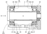
- FIG. 3 is an extraction diagram of positions corresponding to FIG. 2 in the first modification.
- a fixing groove 2f is formed on the inner peripheral surface 2c of the bearing hole 2b.
- Two fixing grooves 2f are provided apart in the axial direction.
- Each of the fixed grooves 2f extends in the rotation direction of the shaft 8.
- a retaining ring 30 (opposing member) is fixed to each fixing groove 2f.
- FIG. 4 is an explanatory diagram for explaining the retaining ring 30, and is a view taken along the arrow IV of the retaining ring 30 in FIG.
- the retaining ring 30 has an arcuate body portion 30a. Both ends (one end 30b and the other end 30c) facing each other with a gap in the circumferential direction of the main body 30a function in the same manner as the inner wall 27a of the outer diameter side spacer 24 described above.
- the outer peripheral surface 30 d of the main body portion 30 a of the retaining ring 30 is press-fitted (fitted) into the fixing groove 2 f, and the retaining ring 30 is fixed to the bearing housing 2.
- the fixing groove 2f is located on the radially outer side of the protruding portion 26 provided in the outer ring 7a.
- the retaining ring 30 is press-fitted into the fixing groove 2f in the gap between both ends in the circumferential direction so that the protruding portion 26 is positioned.
- one end 30 b and the other end 30 c of the retaining ring 30 face the protruding portion 26 in the rotation direction of the shaft 8.
- the one end 30b and the other end 30c are slightly separated from the protrusion 26 in the rotation direction.
- the retaining ring 30 faces the thick side end surface 7f of the outer ring 7a in the axial direction and restricts the movement of the outer ring 7a in the axial direction.
- the retaining ring 30 restricts the movement of the protruding portion 26 in the rotation direction of the shaft 8.
- the cost required for separate members and assembly work can be reduced. Further, the number of parts can be reduced and the cost can be further reduced as compared with the case where a member for restricting the movement of the outer ring 7a in the rotational direction and a member for restricting the movement of the outer ring 7a in the axial direction are provided. Further, since the retaining ring 30 has a small member volume and is inexpensive, it is possible to reduce the weight in addition to cost reduction.
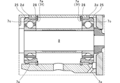
- FIG. 5 is an extraction diagram of positions corresponding to FIG. 2 in the second modified example.
- the case where two annular protrusions 7e are provided for each outer ring 7a has been described.
- one annular protrusion 7e is provided on each outer ring 7a.
- the two annular protrusions 7e are disposed on the outer side in the axial direction with respect to the two oil holes 2d (on the opposite side to the proximity direction of the two ball bearings 7).
- the annular protrusion 7e is located on the opposite side (turbine impeller 9 side) from the retaining ring 30 with respect to the oil hole 2d.
- the annular protrusion 7e is located on the side opposite to the retaining ring 30 (on the compressor impeller 10 side) with respect to the oil hole 2d.
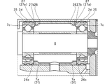
- FIG. 6 is an extraction diagram of positions corresponding to FIG. 2 in the third modified example.
- the oil groove 28 is provided in the end surface 24c of the outer diameter side spacer 24 .
- the oil groove 28 may be provided on the thick side end surface 7f of the outer ring 7a.
- the recess 27 is disposed on the oil hole 2 d side with respect to the shaft 8 without providing the oil groove 28.
- the projecting portion 26 is dimensioned to be separated from the bottom surface 27b of the recessed portion 27. Therefore, part of the lubricating oil after contributing to vibration suppression at the damper portion 25 flows out to the rolling element 7 c side through the gap between the bottom surface 27 b of the recess portion 27 and the protruding portion 26.
- the recess 27 serves as both the restricting portion in the rotational direction of the shaft 8 and the oil groove 28 in the above-described embodiment, the first modified example, and the second modified example.
- the protrusion 26 is provided on the outer ring 7a, and the restricting parts (inner wall 27a, one end 30b, the other end 30c) are provided on the opposing member (outer diameter side spacer 24, retaining ring 30).
- the present invention is not limited to this, and the outer ring may be provided with a restricting portion and the opposing member may be provided with a protruding portion.
- the damper portion 25 includes the annular protrusion 7e
- the annular protrusion 7e is not an essential configuration.
- the ball bearing 7 is an angular bearing and the protruding portion 26 is provided on the thick side end surface 7f has been described.
- the ball bearing 7 is not limited to an angular bearing.
- a restricting portion may be formed on the thick side end surface 7f.
- the following points are superior to the case where the ball bearing 7 is provided on the end surface 7g opposite to the thick side end surface 7f. That is, it is possible to secure a large contact area in the radial direction on the shaft 8 of the protruding portion and the regulating portion, and it is possible to reduce the surface pressure and reduce the influence on wear and the like.
- the outer diameter side spacer 24 is a counter member
- the retaining ring 30 is a counter member
- the present invention is not limited to this, and the facing member may be another member that faces the outer ring 7a in the axial direction.
- the oil groove 28 is not an essential configuration.
Landscapes
- Engineering & Computer Science (AREA)
- General Engineering & Computer Science (AREA)
- Mechanical Engineering (AREA)
- Chemical & Material Sciences (AREA)
- Combustion & Propulsion (AREA)
- Rolling Contact Bearings (AREA)
- Supercharger (AREA)
- Mounting Of Bearings Or Others (AREA)
- Support Of The Bearing (AREA)
Abstract
Priority Applications (4)
| Application Number | Priority Date | Filing Date | Title |
|---|---|---|---|
| JP2017527425A JP6516008B2 (ja) | 2015-07-09 | 2016-07-01 | 軸受構造、および、過給機 |
| CN201680038770.2A CN107835905B (zh) | 2015-07-09 | 2016-07-01 | 轴承结构以及增压器 |
| DE112016003110.6T DE112016003110B4 (de) | 2015-07-09 | 2016-07-01 | Lageraufbau und Turbolader |
| US15/860,100 US10408260B2 (en) | 2015-07-09 | 2018-01-02 | Bearing structure and turbocharger |
Applications Claiming Priority (2)
| Application Number | Priority Date | Filing Date | Title |
|---|---|---|---|
| JP2015-137424 | 2015-07-09 | ||
| JP2015137424 | 2015-07-09 |
Related Child Applications (1)
| Application Number | Title | Priority Date | Filing Date |
|---|---|---|---|
| US15/860,100 Continuation US10408260B2 (en) | 2015-07-09 | 2018-01-02 | Bearing structure and turbocharger |
Publications (1)
| Publication Number | Publication Date |
|---|---|
| WO2017006865A1 true WO2017006865A1 (fr) | 2017-01-12 |
Family
ID=57685491
Family Applications (1)
| Application Number | Title | Priority Date | Filing Date |
|---|---|---|---|
| PCT/JP2016/069665 Ceased WO2017006865A1 (fr) | 2015-07-09 | 2016-07-01 | Structure de palier et surcompresseur |
Country Status (5)
| Country | Link |
|---|---|
| US (1) | US10408260B2 (fr) |
| JP (1) | JP6516008B2 (fr) |
| CN (1) | CN107835905B (fr) |
| DE (1) | DE112016003110B4 (fr) |
| WO (1) | WO2017006865A1 (fr) |
Cited By (4)
| Publication number | Priority date | Publication date | Assignee | Title |
|---|---|---|---|---|
| WO2019135326A1 (fr) * | 2018-01-04 | 2019-07-11 | 株式会社Ihi | Turbocompresseur |
| JP2019203506A (ja) * | 2018-05-25 | 2019-11-28 | ボーグワーナー インコーポレーテッド | 一体型スクィーズフィルムダンパを備えた単列玉軸受 |
| WO2020021908A1 (fr) * | 2018-07-27 | 2020-01-30 | 株式会社Ihi | Structure de palier et turbocompresseur |
| WO2020021822A1 (fr) * | 2018-07-26 | 2020-01-30 | 株式会社Ihi | Structure de palier |
Families Citing this family (3)
| Publication number | Priority date | Publication date | Assignee | Title |
|---|---|---|---|---|
| CN109194006B (zh) * | 2018-09-28 | 2019-08-20 | 浙江江宇电机有限公司 | 电机 |
| US10935080B2 (en) * | 2019-03-14 | 2021-03-02 | Raytheon Technologies Corporation | Extended housing sleeve with stiffening ring feature |
| JPWO2020194381A1 (fr) * | 2019-03-22 | 2020-10-01 |
Citations (7)
| Publication number | Priority date | Publication date | Assignee | Title |
|---|---|---|---|---|
| JP2001041233A (ja) * | 1999-07-26 | 2001-02-13 | Nsk Ltd | 転がり軸受装置 |
| JP2004360778A (ja) * | 2003-06-04 | 2004-12-24 | Ntn Corp | 軸受組込み構造 |
| JP2005172098A (ja) * | 2003-12-10 | 2005-06-30 | Koyo Seiko Co Ltd | ターボチャージャの軸受装置 |
| JP2005171796A (ja) * | 2003-12-09 | 2005-06-30 | Koyo Seiko Co Ltd | ターボチャージャ用軸受装置 |
| JP2011236967A (ja) * | 2010-05-10 | 2011-11-24 | Ihi Corp | すべり軸受構造及び過給機 |
| JP2013024059A (ja) * | 2011-07-15 | 2013-02-04 | Mitsubishi Heavy Ind Ltd | 電動過給圧縮機、その組立方法及び内燃機関 |
| JP2014126091A (ja) * | 2012-12-26 | 2014-07-07 | Nsk Ltd | 複列転がり軸受 |
Family Cites Families (11)
| Publication number | Priority date | Publication date | Assignee | Title |
|---|---|---|---|---|
| JPH0540273Y2 (fr) | 1988-04-26 | 1993-10-13 | ||
| JPH01159132U (fr) | 1988-04-26 | 1989-11-02 | ||
| JPH0710037Y2 (ja) | 1988-05-02 | 1995-03-08 | 日産自動車株式会社 | 過給機の軸受装置 |
| JP2008138779A (ja) | 2006-12-01 | 2008-06-19 | Ntn Corp | 軸支持装置及び円筒ころ軸受の予圧法 |
| JP5075000B2 (ja) | 2008-04-28 | 2012-11-14 | トヨタ自動車株式会社 | 過給機の軸受装置 |
| US8545106B2 (en) | 2009-07-08 | 2013-10-01 | Williams International Co., L.L.C. | System and method for isolating a rolling-element bearing |
| DE102010033823A1 (de) * | 2010-08-09 | 2011-02-24 | Schaeffler Technologies Gmbh & Co. Kg | Radlagereinheit |
| JP6015013B2 (ja) | 2012-01-31 | 2016-10-26 | 株式会社Ihi | 過給機 |
| JP2014125920A (ja) | 2012-12-26 | 2014-07-07 | Nsk Ltd | ターボチャージャ |
| GB201307674D0 (en) | 2013-04-29 | 2013-06-12 | Cummins Ltd | Turbomachine With Axial Stop Member |
| US9963998B2 (en) | 2013-06-18 | 2018-05-08 | Honeywell International Inc. | Assembly with bearings and spacer |
-
2016
- 2016-07-01 JP JP2017527425A patent/JP6516008B2/ja active Active
- 2016-07-01 CN CN201680038770.2A patent/CN107835905B/zh active Active
- 2016-07-01 WO PCT/JP2016/069665 patent/WO2017006865A1/fr not_active Ceased
- 2016-07-01 DE DE112016003110.6T patent/DE112016003110B4/de active Active
-
2018
- 2018-01-02 US US15/860,100 patent/US10408260B2/en active Active
Patent Citations (7)
| Publication number | Priority date | Publication date | Assignee | Title |
|---|---|---|---|---|
| JP2001041233A (ja) * | 1999-07-26 | 2001-02-13 | Nsk Ltd | 転がり軸受装置 |
| JP2004360778A (ja) * | 2003-06-04 | 2004-12-24 | Ntn Corp | 軸受組込み構造 |
| JP2005171796A (ja) * | 2003-12-09 | 2005-06-30 | Koyo Seiko Co Ltd | ターボチャージャ用軸受装置 |
| JP2005172098A (ja) * | 2003-12-10 | 2005-06-30 | Koyo Seiko Co Ltd | ターボチャージャの軸受装置 |
| JP2011236967A (ja) * | 2010-05-10 | 2011-11-24 | Ihi Corp | すべり軸受構造及び過給機 |
| JP2013024059A (ja) * | 2011-07-15 | 2013-02-04 | Mitsubishi Heavy Ind Ltd | 電動過給圧縮機、その組立方法及び内燃機関 |
| JP2014126091A (ja) * | 2012-12-26 | 2014-07-07 | Nsk Ltd | 複列転がり軸受 |
Cited By (15)
| Publication number | Priority date | Publication date | Assignee | Title |
|---|---|---|---|---|
| WO2019135326A1 (fr) * | 2018-01-04 | 2019-07-11 | 株式会社Ihi | Turbocompresseur |
| DE112018006765B4 (de) | 2018-01-04 | 2024-03-28 | Ihi Corporation | Turbolader |
| CN111479991A (zh) * | 2018-01-04 | 2020-07-31 | 株式会社Ihi | 增压器 |
| JPWO2019135326A1 (ja) * | 2018-01-04 | 2020-12-10 | 株式会社Ihi | 過給機 |
| US11339794B2 (en) | 2018-01-04 | 2022-05-24 | Ihi Corporation | Turbocharger |
| JP2019203506A (ja) * | 2018-05-25 | 2019-11-28 | ボーグワーナー インコーポレーテッド | 一体型スクィーズフィルムダンパを備えた単列玉軸受 |
| JP7597504B2 (ja) | 2018-05-25 | 2024-12-10 | ボーグワーナー インコーポレーテッド | 一体型スクィーズフィルムダンパを備えた単列玉軸受 |
| US11187267B2 (en) | 2018-07-26 | 2021-11-30 | Ihi Corporation | Bearing structure |
| JPWO2020021822A1 (ja) * | 2018-07-26 | 2021-05-13 | 株式会社Ihi | 軸受構造 |
| WO2020021822A1 (fr) * | 2018-07-26 | 2020-01-30 | 株式会社Ihi | Structure de palier |
| JPWO2020021908A1 (ja) * | 2018-07-27 | 2021-05-13 | 株式会社Ihi | 軸受構造および過給機 |
| CN112154261A (zh) * | 2018-07-27 | 2020-12-29 | 株式会社Ihi | 轴承构造以及增压器 |
| JP7107371B2 (ja) | 2018-07-27 | 2022-07-27 | 株式会社Ihi | 軸受構造および過給機 |
| US11441602B2 (en) | 2018-07-27 | 2022-09-13 | Ihi Corporation | Bearing structure and turbocharger |
| WO2020021908A1 (fr) * | 2018-07-27 | 2020-01-30 | 株式会社Ihi | Structure de palier et turbocompresseur |
Also Published As
| Publication number | Publication date |
|---|---|
| DE112016003110T5 (de) | 2018-04-12 |
| JPWO2017006865A1 (ja) | 2018-04-12 |
| DE112016003110B4 (de) | 2023-10-19 |
| CN107835905A (zh) | 2018-03-23 |
| US20180119572A1 (en) | 2018-05-03 |
| US10408260B2 (en) | 2019-09-10 |
| JP6516008B2 (ja) | 2019-05-22 |
| CN107835905B (zh) | 2020-06-12 |
Similar Documents
| Publication | Publication Date | Title |
|---|---|---|
| JP6516008B2 (ja) | 軸受構造、および、過給機 | |
| JP6288267B2 (ja) | 軸受構造、および、過給機 | |
| CN101517241B (zh) | 真空泵 | |
| CN108350932B (zh) | 轴承构造以及增压器 | |
| CN103180570A (zh) | 具有轴向推力阻尼和抗转动组件的滚动元件轴承套筒 | |
| JP6927333B2 (ja) | 過給機 | |
| US11441602B2 (en) | Bearing structure and turbocharger | |
| JP2017186964A (ja) | ターボチャージャ用軸受機構 | |
| WO2016027617A1 (fr) | Structure de palier et compresseur à suralimentation | |
| WO2017026292A1 (fr) | Structure de palier et compresseur d'alimentation | |
| JP2014125921A (ja) | ターボチャージャ用玉軸受ユニット | |
| JP6469716B2 (ja) | 排気ガスターボチャージャーのための軸受装置および排気ガスターボチャージャー | |
| JP2019178756A (ja) | 軸受構造および過給機 | |
| JPWO2018030179A1 (ja) | 過給機 | |
| JP5569114B2 (ja) | 過給機 | |
| JPWO2017026293A1 (ja) | 軸受構造、および、過給機 | |
| JP2016113937A (ja) | ターボチャージャ用軸受機構 | |
| CN112469910B (zh) | 轴承结构 | |
| JP6539507B2 (ja) | 軸受ユニット | |
| JP2007071356A (ja) | ターボチャージャ用回転支持装置 | |
| JP2014238010A (ja) | 過給機 | |
| WO2020017136A1 (fr) | Surcompresseur | |
| US11493052B2 (en) | Bearing and turbocharger | |
| WO2017014084A1 (fr) | Structure de palier et compresseur à suralimentation | |
| WO2020059370A1 (fr) | Structure porteuse et turbocompresseur |
Legal Events
| Date | Code | Title | Description |
|---|---|---|---|
| 121 | Ep: the epo has been informed by wipo that ep was designated in this application |
Ref document number: 16821334 Country of ref document: EP Kind code of ref document: A1 |
|
| ENP | Entry into the national phase |
Ref document number: 2017527425 Country of ref document: JP Kind code of ref document: A |
|
| WWE | Wipo information: entry into national phase |
Ref document number: 112016003110 Country of ref document: DE |
|
| 122 | Ep: pct application non-entry in european phase |
Ref document number: 16821334 Country of ref document: EP Kind code of ref document: A1 |