WO2017007016A1 - ウエアラブル電極 - Google Patents
ウエアラブル電極 Download PDFInfo
- Publication number
- WO2017007016A1 WO2017007016A1 PCT/JP2016/070267 JP2016070267W WO2017007016A1 WO 2017007016 A1 WO2017007016 A1 WO 2017007016A1 JP 2016070267 W JP2016070267 W JP 2016070267W WO 2017007016 A1 WO2017007016 A1 WO 2017007016A1
- Authority
- WO
- WIPO (PCT)
- Prior art keywords
- lining
- electrode
- wiring
- wearable
- engaged
- Prior art date
- Legal status (The legal status is an assumption and is not a legal conclusion. Google has not performed a legal analysis and makes no representation as to the accuracy of the status listed.)
- Ceased
Links
Images





Classifications
-
- A—HUMAN NECESSITIES
- A61—MEDICAL OR VETERINARY SCIENCE; HYGIENE
- A61B—DIAGNOSIS; SURGERY; IDENTIFICATION
- A61B5/00—Measuring for diagnostic purposes; Identification of persons
- A61B5/68—Arrangements of detecting, measuring or recording means, e.g. sensors, in relation to patient
- A61B5/6801—Arrangements of detecting, measuring or recording means, e.g. sensors, in relation to patient specially adapted to be attached to or worn on the body surface
- A61B5/6802—Sensor mounted on worn items
- A61B5/6804—Garments; Clothes
- A61B5/6805—Vests, e.g. shirts or gowns
-
- A—HUMAN NECESSITIES
- A61—MEDICAL OR VETERINARY SCIENCE; HYGIENE
- A61B—DIAGNOSIS; SURGERY; IDENTIFICATION
- A61B5/00—Measuring for diagnostic purposes; Identification of persons
- A61B5/24—Detecting, measuring or recording bioelectric or biomagnetic signals of the body or parts thereof
- A61B5/25—Bioelectric electrodes therefor
- A61B5/251—Means for maintaining electrode contact with the body
- A61B5/256—Wearable electrodes, e.g. having straps or bands
-
- A—HUMAN NECESSITIES
- A61—MEDICAL OR VETERINARY SCIENCE; HYGIENE
- A61B—DIAGNOSIS; SURGERY; IDENTIFICATION
- A61B5/00—Measuring for diagnostic purposes; Identification of persons
- A61B5/24—Detecting, measuring or recording bioelectric or biomagnetic signals of the body or parts thereof
- A61B5/25—Bioelectric electrodes therefor
- A61B5/263—Bioelectric electrodes therefor characterised by the electrode materials
- A61B5/268—Bioelectric electrodes therefor characterised by the electrode materials containing conductive polymers, e.g. PEDOT:PSS polymers
-
- A—HUMAN NECESSITIES
- A61—MEDICAL OR VETERINARY SCIENCE; HYGIENE
- A61B—DIAGNOSIS; SURGERY; IDENTIFICATION
- A61B5/00—Measuring for diagnostic purposes; Identification of persons
- A61B5/24—Detecting, measuring or recording bioelectric or biomagnetic signals of the body or parts thereof
- A61B5/25—Bioelectric electrodes therefor
- A61B5/279—Bioelectric electrodes therefor specially adapted for particular uses
- A61B5/28—Bioelectric electrodes therefor specially adapted for particular uses for electrocardiography [ECG]
-
- A—HUMAN NECESSITIES
- A61—MEDICAL OR VETERINARY SCIENCE; HYGIENE
- A61B—DIAGNOSIS; SURGERY; IDENTIFICATION
- A61B5/00—Measuring for diagnostic purposes; Identification of persons
- A61B5/24—Detecting, measuring or recording bioelectric or biomagnetic signals of the body or parts thereof
- A61B5/316—Modalities, i.e. specific diagnostic methods
- A61B5/318—Heart-related electrical modalities, e.g. electrocardiography [ECG]
- A61B5/321—Accessories or supplementary instruments therefor, e.g. cord hangers
- A61B5/322—Physical templates or devices for measuring ECG waveforms, e.g. electrocardiograph rulers or calipers
-
- A—HUMAN NECESSITIES
- A61—MEDICAL OR VETERINARY SCIENCE; HYGIENE
- A61B—DIAGNOSIS; SURGERY; IDENTIFICATION
- A61B2562/00—Details of sensors; Constructional details of sensor housings or probes; Accessories for sensors
- A61B2562/02—Details of sensors specially adapted for in-vivo measurements
- A61B2562/0209—Special features of electrodes classified in A61B5/24, A61B5/25, A61B5/283, A61B5/291, A61B5/296, A61B5/053
-
- A—HUMAN NECESSITIES
- A61—MEDICAL OR VETERINARY SCIENCE; HYGIENE
- A61B—DIAGNOSIS; SURGERY; IDENTIFICATION
- A61B2562/00—Details of sensors; Constructional details of sensor housings or probes; Accessories for sensors
- A61B2562/22—Arrangements of medical sensors with cables or leads; Connectors or couplings specifically adapted for medical sensors
- A61B2562/221—Arrangements of sensors with cables or leads, e.g. cable harnesses
- A61B2562/222—Electrical cables or leads therefor, e.g. coaxial cables or ribbon cables
Definitions
- the present invention relates to a wearable electrode.
- This application claims priority based on Japanese Patent Application No. 2015-137288 for which it applied on July 8, 2015, and uses the content here.
- Non-Patent Document 1 medical standards (for example, see Non-Patent Document 1) are defined for the electrode part and the wiring part.
- an object of the present invention is to provide a wearable electrode in which movement of an electrode portion is suppressed even when clothes worn by a user move.
- One aspect of the present invention is to acquire a biological signal generated by the living body in contact with a living body wearing the clothing, a clothing having a surface covering and at least a part of the inner surface of the outer surface, and the surface of the backing
- the outer surface and the lining are wearable electrodes connected at a portion other than the portion where the electrode portion is attached on the lining.
- a wiring portion disposed between the outer surface and the lining is provided, and one of the electrode portion and the wiring portion is provided with a convex portion and is formed of a conductive material.
- the other part of the electrode part and the wiring part is provided with a recessed part that is detachably engaged with the raised part, and an engaged part formed of a conductive material is electrically connected.
- the outer surface of the outer region and the pair of outer surfaces are arranged on the outer surface so as to avoid a region where the user who wears the clothes moves a neck or an arm relatively moving compared to other regions.
- a neckline is formed, and the lining has a neckline and a lining at the neckline so as to avoid a part that moves relatively more than other parts when a user wearing the clothes moves a neck or an arm.
- a pair of lining armholes are formed.
- the elongation rate in the vertical direction and the width direction measured based on the provisions of the A method is smaller than the elongation rate in each of the portions other than the sandwiched portion in the lining.
- the present invention it is possible to suppress the movement of the electrode portion even when the clothes worn by the user move.
- the wearable electrode 1 includes an undergarment (clothing) 10 having a surface material 11 and a lining material 12, a wiring part 35 disposed between the surface material 11 and the lining material 12, and a lining material. 12 and the electrode part 45 attached to the opposite side to the surface material 11 is provided.
- the surface material 11 is shown with the dashed-two dotted line. Below, the electrode part 45 is demonstrated first.
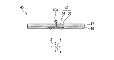
- the electrode unit 45 includes an electrode 46 formed in a flat plate shape and a waterproof layer 47 laminated on the electrode 46.
- the electrode 46 is formed of a conductive fiber structure obtained by impregnating a conductive polymer into a fiber structure as a base fabric that is a base material. Examples of the form of the fiber structure used for the electrode 46 include woven fabric, knitted fabric and non-woven fabric. If the amount of the conductive resin (conductive polymer) impregnated in the fiber structure is insufficient, washing durability in repeated use cannot be obtained, so the basis weight of the fiber structure (unit weight as the base fabric) is It is preferably 50 g / m 2 or more and 300 g / m 2 or less.
- the impregnation amount of the conductive resin is reduced, and washing durability cannot be obtained.
- the wearing feeling is inferior. More preferably, it is 60 g / m 2 or more and 250 g / m 2 or less.
- the thickness of the fiber structure is preferably 0.2 mm or more and 2.0 mm or less. If the thickness is less than 0.2 mm, the fabric is too thin and the basis weight is reduced, and the impregnation amount of the conductive resin is reduced. If the thickness exceeds 2.0 mm, it is too thick and the wear feeling is inferior. More preferably, it is 0.3 mm or more and 1.5 mm or less.
- the fiber structure is preferably a woven fabric, a knitted fabric, or a non-woven fabric, more preferably, It is a highly flexible knitted fabric.
- a member for reinforcement may be disposed on the back side of the electrode 46 when the electrode 46 bends or moves when worn.
- the structure and manufacturing method of the fiber structure represented by the knitted fabric are not particularly limited, but the electrode 46 preferably has a shape that retains moisture such as sweat, and the knitted fabric can preferably use a double knit. Examples thereof include, but are not limited to, a double Russell structure, a corrugated cardboard structure, a reversible structure, a smooth structure, a milling structure, and a back hair structure.
- the woven or knitted fabric used for the electrode 46 of the present invention preferably includes a multifilament yarn composed of a plurality of single fibers from the viewpoint of supporting the conductive resin on the fiber structure and high conductivity.
- the fineness of the multifilament yarn is not particularly limited, it is preferably 30 dtex to 400 dtex from the viewpoint of utilizing the characteristics as a fiber structure.
- the mixing ratio of the multifilament yarn in the woven or knitted fabric is not particularly limited as long as it does not affect the performance, but a higher mixing ratio is preferable from the viewpoint of conductivity and durability, and more preferably 50% to 100%. It is.
- the material of the multifilament yarn used for the woven or knitted fabric can be, for example, polyester synthetic fibers such as polyethylene terephthalate, polytrimethylene terephthalate, polybutylene terephthalate, and polyamide synthetic fibers such as nylon. It is not a thing to be done. Moreover, what mix
- the cross-sectional shape of a single fiber unit constituting the multifilament is not specified, and various irregular cross-sectional yarns represented by a round shape, a triangular shape, an eight-leaf shape, a flat shape, and a Y shape can also be used.
- the inelastic yarn a core sheath or a side-by-side type composite yarn made of polymers having different viscosities can be used.
- false twisted yarn obtained by false twisting these raw yarns may be used.
- synthetic fibers such as polyacrylonitrile and polypropylene, regenerated fibers such as rayon, polynosic and cupra, semisynthetic fibers such as acetate and triacetate, and natural fibers represented by silk can be used.
- the fiber structure according to the present invention preferably contains a multifilament having a fiber diameter of a single fiber of 0.2 dtex or less from the viewpoint of supporting the conductive resin on the fiber surface and the gap between the fibers.
- the mixing ratio in the fiber structure of single fibers and multifilaments of 0.2 dtex or less is not particularly limited as long as it does not affect the performance, but a higher mixing ratio is preferable from the viewpoint of conductivity and durability, and more preferably. It is 50% or more and 100% or less.
- the gap formed by a plurality of single fibers i.e., the portion on which the conductive resin is supported is subdivided, thereby increasing the supportability of the conductive resin to the fiber structure,
- the continuity of the conductive resin is maintained even if the fiber diameter is reduced, the excellent conductivity and washing durability can be obtained.
- microfibers having a fiber diameter of 5 ⁇ m or less used for artificial leather and outer materials are used, and more preferably, for the purpose of preventing slippage in linings for sports clothing, brassiere, golf gloves and the like in recent years. It is more preferable to use nanofibers having a fiber diameter of 10 nm to 1000 nm.
- Nanofibers include nanofibers produced by known methods such as nanofiber staple yarn assemblies produced from “Nanoalloy (registered trademark)” fibers, monofilament yarn assemblies produced by electrospinning, etc. Although a fiber structure can be used suitably, the fiber structure containing the multifilament yarn of nanofiber is more preferable.
- the nanofiber multifilament yarn can be produced by a known composite spinning method or the like.
- nanofiber multifilament yarns with small variations in fiber diameter obtained by removing the composite fiber using the composite base exemplified in JP2013-185283A can be effectively used, but are not limited thereto. It is not a thing.
- sea removal refers to processing that melts the sea component of the fiber and leaves the island component.
- a polymer containing a mixture of poly 3,4-ethylenedioxythiophene and polystyrene sulfonic acid can be preferably used.
- PEDOT-PSS polystyrene sulfonic acid
- pyrrole-based, thiophene-based, isothianaphthene-based, phenylene-based, acetylene-based, and aniline-based conductive polymers, and copolymers thereof can be used as the conductive polymer. .
- dopants of these conductive polymers include, for example, halide ions, perchlorate ions, tetrafluoroborate ions, hexafluoroarsenate ions, sulfate ions, nitrate ions, thiocyanate ions, phosphate ions, trifluoro ions.
- polymer ions such as acetate ion, tosylate ion, alkylsulfonate ion, polyacrylate ion, at least one ion may be used.
- the electrode 46 made of the fiber structure according to the present invention has low irritation at the time of contact with the skin and high safety. When a signal cannot be obtained satisfactorily due to skin drying or the like, it is preferable to apply a small amount of physiological saline or a moisturizing agent to the fiber structure.
- a humectant for example, glycerol, sorbitol, polyethylene glycol, polyethylene glycol-polypropylene glycol copolymer, ethylene glycol, sphingosine, phosphatidylcholine and the like can be used, and one of these may be used alone, or two or more May be used in combination.
- the size and shape of the electrode 46 are not particularly limited as long as a biological signal can be detected, and the lengths of the vertical and horizontal sides are preferably 2 cm or more and 20 cm or less, respectively.
- the length and width of the electrode 46 are less than 2 cm each, the area of the electrode 46 is too small, so that the electrode 46 is easily displaced when clothes move during exercise, and noise is easily picked up. If it exceeds 20 cm, the size is not necessary for substantial signal detection, and the area of the electrode 46 is too large, so that the distance between adjacent electrodes is small, and a trouble such as a short circuit is likely to occur.
- the vertical and horizontal lengths are 2.5 cm or more and 18 cm or less, respectively. More preferably, as shown in FIG. 4, for example, a square of about 4 cm ⁇ 4 cm and having a shape with rounded corners is used.
- the waterproof layer 47 is a layer that does not transmit liquid moisture.
- the waterproof layer 47 here is not necessarily required, but is preferably laminated as a resin layer on one side of a fiber structure containing a conductive substance.
- the resin layer is laminated on the back side of the surface in contact with the skin side of the fiber structure used for the electrode 46.
- the type and shape of the polymer constituting the resin layer is not particularly limited as long as it does not permeate liquid.
- a method of laminating polymer films such as acrylic and vinyl chloride, acrylic resin, urethane resin And the like.
- a waterproof moisture-permeable layer is preferable.
- the waterproof layer 47 is preferably a laminate of stretchable polyurethane resin microporous films laminated.
- micropores may be formed in a fiber structure having a resin layer laminated on one side using a punching machine or a sewing machine.
- the electrode 46 of the electrode part 45 acquires the electrical biosignal which the user P emits in contact with the user P who wears the underwear 10 so that it may mention later.
- the electrode part 45 is provided with a male button (engagement part) 49.
- the male button 49 has a known configuration and has a side 50 and a gene 51.
- the hoso 50 and the genko 51 are each formed of a conductive material such as stainless steel.
- the hoso 50 is disposed on the electrode 46 side, and the genko 51 is disposed on the waterproof layer 47 side.
- a part of the hoso 50 is embedded in the electrode 46, and a part of the base 51 is embedded in the waterproof layer 47. For this reason, the level
- the side 50 and the genco 51 are electrically connected.
- the male button 49 is provided near the center of the electrode 46 and the waterproof layer 47.
- the male button 49 is electrically connected to the electrode part 45.
- the male button 49 mechanically connects the underwear 10 and the electrode part 45 to support the vicinity of the central part of the electrode part 45 at a single point, and the electrode part 45 is measured by a measuring device (processing) via a female button 39 described later. It also serves to electrically connect to the device D).
- the outer material 11 is formed by sewing the front body 14 and the back body 15 together.
- the front body 14 is formed in a rectangular shape so that when the user P wears the underwear 10, the front body 16 is disposed below, and the front body neckline 17 is formed in a Y shape and disposed above. have.
- the back body 15 is formed in a rectangular shape, and when the user P wears the underwear 10, the back body body 18 is disposed below, and the back body neckline 19 is formed in a Y shape and disposed above. have.
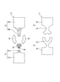
- the lining 12 is formed by sewing together a front body 21, a back center (a sandwiched portion) 22, a pair of back shoulders 23, and a back body 24.
- the front body 21 is formed in a shape in which a belt-like portion 21b protrudes outward from a central portion of one side of a front body body 21a formed in a rectangular shape. It should be noted that the belt-like portion 21b and a belt-like portion 24b described later are indicated by hatching.
- the back body 24 is formed in a shape in which a belt-like portion 24b protrudes outward from the central portion of one side of the back body main body 24a formed in a rectangular shape.
- the back center 22 is formed in a Y shape.
- the back shoulders 23 are each formed in a C shape.
- the area of one surface of the back center 22 is 100 cm 2 or more and 200 cm 2 or less.
- the area of one surface mentioned here is demonstrated using FIG.
- the back center 22 is configured by weaving fibers 22a, for example.
- a plane Q perpendicular to the thickness direction Z of the back center 22 is defined.
- the area of one surface 22b of the back center 22 is an area B1 obtained by projecting the one surface 22b of the back center 22 in the thickness direction Z and projecting the one surface 22b on the plane Q. Means.
- the area of one surface 22b of the back center 22 does not mean the area B2 of the surface of the fiber 22a on the one surface 22b side.
- the outer material 11 and the lining 12 can be formed of cloth or the like.
- the fabric of the lining 12 and the outer material 11 may be different.
- the elongation in the vertical direction and the width direction measured based on the JIS L 1096 8.16.1 A method at the back center 22 is the portion other than the back center 22 in the lining 12, that is, the front body 21 and the back shoulder 23. , And the elongation rate of the back body 24 is smaller. It is preferable that the elongation in the vertical direction and the horizontal direction measured in accordance with JIS L 1096 8.16.1 A method of the back center 22 is 15% or less, respectively.
- the back center 22 By configuring the back center 22 in this way, it is possible to secure the necessary pressure when the electrocardiogram is measured while wearing the underwear 10 having the lining 12. In addition, when the area of one surface of the back center 22 is larger than 200 cm 2, the feeling of wearing is deteriorated, and when the area of one surface of the back center 22 is less than 100 cm 2 , the effect of securing the pressure when wearing the lining 12 is obtained. No.
- the width of the narrowest part of the front body 14 of the outer material 11 and the front body 21 of the lining 12 is preferably 12 cm or less. When the length exceeds 12 cm, the fabric is easily pulled under the influence of the expansion and contraction of the skin when the arm is shaken. As a result, the electrode part 45 is liable to be displaced with respect to the skin, which is not preferable.
- the width of the narrowest part of the rear body 15 of the outer material 11 and the rear body 24 of the lining 12 is preferably 17 cm or less. When it exceeds 17 cm, the fabric is easily pulled due to the influence of stretching and contraction of the skin when the arm is shaken. As a result, the electrode part 45 is liable to be displaced with respect to the skin, which is not preferable.
- the outer neck portion 11a and the pair of outer armhole portions 11b are formed so as to avoid a portion having a relatively large movement compared to other portions.
- the part relatively moving compared to other parts mentioned here includes the neck P3 and the arm P4.
- the lining 12 has a lining neck 12c and a neckline portion 12c so as to avoid a portion that moves relatively more than other portions.
- a pair of lining armholes 12d are formed.
- the front body neckline portion 17 and the back body neckline portion 19 sandwiched between the outer neckline portion 11a and the pair of outer surface neckline portions 11b are formed in a Y-shape with belt-like members.
- the belt-like portions 21b and 24b and the back shoulder 23 sandwiched between the lining neckline portion 12c and the pair of lining armhole portions 12d are formed in a belt shape.
- the back center 22 is a portion sandwiched between the lining neckline portion 12c and the pair of lining armhole portions 12d in the portion of the lining 12 that is in front of the user P wearing the undergarment 10.
- the back center 22 opposes the sternum handle (portion between a pair of clavicles) of the user P wearing the underwear 10.
- the inner diameter L1 of the armpit portion of the outer fabric 11 and the inner diameter L2 of the armpit portion of the lining 12 are each 24 cm or more.
- the width of the back center 22 is the narrowest.
- the lining 12 is formed with slits 12 a extending in the vertical direction.
- the surface material 11 is not shown, and a part of a reinforcing cloth 26 to be described later is shown broken away.
- the slit 12a penetrates the lining 12 in the thickness direction.
- the length L in the vertical direction of the slit 12a is preferably shorter than the length of the short side of the electrode portion 45.
- the electrode 46 is 4 cm square, it is preferably less than 4 cm (see FIG. 7).
- the width of the slit 12a is not particularly limited as long as the head 50a of the hoso 50 is movable along the slit 12a, but the outer diameter of the head 50a is preferably about.
- the head 50a inserted through the slit 12a can move in the vertical direction along the slit 12a.
- the slit 12a is preferably formed at a position facing the chest P1 of the user P when the user P wears the underwear 10 of the wearable electrode 1.
- the outer material 11 and the lining material 12 are each formed in a cylindrical shape.
- the lining 12 covers at least a part of the inner surface of the outer material 11.
- the outer material 11 and the lining material 12 are formed in a shape that avoids parts such as muscles that are interlocked by the movement of the neck P3 or the arm P4.
- a reinforcing cloth 26 may be provided between the lining 12 and the outer surface 11.
- the reinforcing cloth 26 is formed in a rectangular shape with a desired cloth, for example.
- the reinforcing cloth 26 is disposed so as to cover the slit 12 a of the lining 12.
- the lining 12 and the reinforcing cloth 26 are connected by a pair of seams 27 formed by, for example, sewing the lining 12 and the reinforcing cloth 26 with a thread.
- Each seam 27 is formed so as to extend in the vertical direction and be separated from each other.
- the lining 12, the slit 12 a, the reinforcing cloth 26, and the pair of seams 27 configured as described above constitute a cylindrical structure 28. In this example, a plurality of cylindrical structures 28 are formed on the backing 12.
- Each cylindrical structure 28 is disposed at a position based on any of NASA guidance, CM5 guidance, CC5 guidance, and chest guidance C1-6 (hereinafter referred to as NASA guidance or the like). As will be described later, since the electrode portions 45 are attached through the slits 12a, each electrode portion 45 is disposed at a position based on NASA induction or the like.
- the surface material 11 and the lining material 12 are connected by a connecting portion 30 such as a seam provided above the reinforcing cloth 26. That is, the outer surface 11 and the lining 12 are connected to each other at a portion other than the slit 12a, which is a portion to which the electrode portion 45 is attached, as will be described later. As will be described later, the electrode portion 45 is attached to the backing 12 through the slit 12a. It is assumed that the portion closest to the slit 12 a among the portions where the lining 12 and the outer surface 11 are connected is the connection portion 30.
- the connecting portion 30 is separated from the slit 12a of the lining 12, and is preferably separated by 1 cm or more.
- An annular loop portion (wiring holding portion) 31 may be provided on the backing 12 above the slit 12a.
- the loop portion 31 is provided on the backing 12 above the slit 12a.
- the loop portion 31 may be provided on the outer surface 11 above the slit 12a.
- the wiring part 35 includes a support plate 36 disposed in the cylindrical structure 28 and a connection wiring 37 having a first end connected to the support plate 36.
- the support plate 36 is formed in a rectangular shape with a desired resin plate or cloth.
- the support plate 36 preferably has a certain rigidity so that it can easily move within the cylindrical structure 28.
- the width of the support plate 36 is shorter than the distance between the pair of seams 27.
- the support plate 36 is movable in the vertical direction within the cylindrical structure 28 with the pair of seams 27 as a guide. The position of the support plate 36 in the vertical direction is maintained by the frictional force generated between itself, the lining 12 and the reinforcing cloth 26.
- a female button (engaged portion) 39 is provided near the center of the support plate 36 of the wiring portion 35.
- the male button 49 and the female button 39 constitute a dot button 38.
- the female button 39 has a known configuration provided on the underwear 10 and includes an head 40 and a spring 41.
- the head 40 and the spring 41 are each formed of a conductive material such as stainless steel.
- the head 40 is disposed on the reinforcing cloth 26 side, and the spring 41 is disposed on the lining 12 side.
- the head 40 and the spring 41 are electrically connected.
- the head 40 is provided with a recess 40a that is detachably engaged with the head 50a of the lever 50.
- the recess 40 a includes a shape of a hole that penetrates the head 40.
- the female button 39 is electrically connected to the connection wiring 37 of the wiring part 35.
- the head portion 50a of the male button 49 inserted through the slit 12a of the lining 12 can be engaged with the concave portion 40a of the female button 39. That is, the female button 39 and the male button 49 arranged so as to sandwich the slit 12a are engaged and integrated, and move vertically along the slit 12a (a pair of seams 27). When the male button 49 and the female button 39 are engaged, the male button 49 and the female button 39 are electrically connected.
- connection wiring 37 a known one such as a so-called flexible wiring can be appropriately selected and used.
- a core wire (not shown) of the connection wiring 37 is electrically connected to the female button 39.
- the connection wiring 37 is drawn upward from the female button 39 and routed downward after passing through the loop portion 31. That is, the loop portion 31 holds the connection wiring 37.
- a second end of the connection wiring 37 is connected to the measuring device D.
- the measuring device D has a known configuration capable of processing an electrical biological signal emitted by the user P. As shown in FIG. 1, the measuring device D is held in a storage portion 12 b such as a pocket provided in the lining 12, for example. The measuring device D may be held in a storage section provided on the outer surface 11 or in a waist bag attached to the user P.
- the wearable electrode 1 configured as described above will be described.
- the user P washes the underwear 10 from which the wiring part 35 and the electrode part 45 have been removed.
- the support plate 36 of the electrode part 45 is inserted into each cylindrical structure 28 of the underwear 10.
- the male button 49 is engaged with the female button 39 by inserting the head 50 a of the male button 49 through the slit 12 a of the lining 12 and engaging the head 50 a of the male button 49 with the recess 40 a of the female button 39.
- the wearable electrode 1 is configured by placing the measuring device D in the storage portion 12b. At this time, the female button 39 and the male button 49 are electrically connected.
- the electrode 46 of the electrode part 45 comes into contact with the skin or the like of the chest P1 of the user P. Since the electrode 46 is easily deformed, the electrode 46 is easily deformed in accordance with the shape of the chest P1 and the like, and a biological signal emitted by the user P can be easily acquired by the electrode 46.
- the waterproof layer 47 is a waterproof and moisture permeable layer, the chest P1 and the like are not easily stuffy because moisture passes therethrough.
- the underwear 10 covers at least one part of the user's P rib, rib cartilage, sternum, and clavicle.
- the electrode part 45 attached to the back center 22 of the lining 12 and disposed so as to face the chest P1 of the user P, more specifically, the sternum (part between a pair of clavicles), particularly the electrode part 45a. (Refer to FIG. 1). Since the electrode part 45 is attached to the lining 12, it does not easily float from the chest P1 of the user P. Since the electrode part 45a is attached to the back center 22 of the lining 12, and is pulled from three directions by the back shoulder 23 and the band-like part 21b which are band-like members, it is particularly difficult to float from the chest part P1.
- the sticking effect of the electrode part 45 on the skin due to the wettability and the viscosity is stable when the following four conditions are satisfied.
- the first is to bring the electrode part 45 into contact with the skin in parallel (flat).
- the second is to support the vicinity of the central part of the electrode part 45 and press it against the skin side.
- the third is not to shift (do not shift) the electrode part 45 on the skin.
- the fourth is not to lose the moisturizer (eg by dry diffusion).
- causes of the above four conditions being lost and the failure or interruption of the measurement are the force to peel the electrode portion 45 from the skin surface (force in the horizontal and vertical directions), skin deformation due to body movement, loss of moisturizer ( And the like).
- the user P adjusts the position of the electrode unit 45 by appropriately moving the electrode unit 45 in the vertical direction as necessary.
- the biological signal acquired by the electrode 46 of the electrode unit 45 is transmitted to the measuring device D through the male button 49, the female button 39, and the connection wiring 37 that are electrically connected to each other.
- the measuring device D When the measuring device D is activated, measurement of a biological signal such as an electrocardiographic waveform is started.
- the user P performs an operation such as walking while measuring a biological signal.
- the outer surface 11 of the undergarment 10 may move. Since the connection part 30 is spaced apart from the slit 12a of the lining 12, it is suppressed that the movement of the surface material 11 is transmitted to the slit 12a of the lining 12. For this reason, the state where the electrode 46 of the electrode unit 45 is in contact with the chest P1 of the user P or the like is maintained.
- the connection wiring 37 near the measuring device D is pulled, the force acting on the connection wiring 37 is received by the loop portion 31 and then transmitted to the female button 39. This suppresses the force with which the connection wiring 37 is pulled from being transmitted to the female button 39.
- the electrode part 45 is not pulled downward by the weight of the connection wiring 37, and the adhesion of the electrode part 45 to the skin can be enhanced.
- the outer material 11 is formed with an outer material neckline portion 11a and a pair of outer material neckline portions 11b
- the lining material 12 is formed with a lining neckline portion 12c and a pair of lining armhole portions 12d.
- the back center 22 is formed of a material that is harder than the front body 21, the back shoulder 23, and the back body 24 and hard to extend. For this reason, even if the underwear 10 moves, it is suppressed that the back center 22 is extended, and the electrode part 45a is hard to leave
- the wearable electrode 1 of the present embodiment when the outer surface 11 of the undergarment 10 worn by the user P moves, the slit 12a and the connecting portion 30 are provided in different portions of the lining 12. Therefore, the movement of the surface material 11 is not easily transmitted to the electrode part 45 through the connection part 30. Therefore, it is possible to suppress the movement of the electrode unit 45.
- the electrode 46 formed of a conductive fiber structure has a feature suitable for long-term measurement with almost no discomfort during wearing. Further, as long as the adhesive force is not lost, a stable contact state with the skin can be maintained, so that a long-term measurement of a biological signal becomes possible. Since the wiring part 35 is sandwiched between the outer material 11 and the lining 12, the wiring part 35 is less likely to come into direct contact with the skin.
- a male button 49 is provided on the electrode part 45, a female button 39 is provided on the wiring part 35, and the head part 50 a of the male button 49 is inserted into the slit 12 a formed in the lining 12.
- the male button 49 and the female button 39 engaged with each other can move along the slit 12a. Therefore, the position of the electrode part 45 with respect to the underwear 10 can be adjusted. Since the wearable electrode 1 includes the loop portion 31, the force when the loop portion 31 is pulled is received by the loop portion 31. Therefore, transmission of the pulled force to the female button 39 can be suppressed.
- a front neckline 11a and a pair of outer necklines 11b are formed on the outer material 11, and a lining neckline 12c and a pair of lining armholes 12d are formed on the lining 12.
- the underwear 10 has a shape that covers the upper chest while avoiding the neck P3 and the arm P4. Therefore, since the entire chest P1 is not compressed, it is difficult to feel stuffy due to tightening. Since the outer material 11 and the lining material 12 are formed in a shape that avoids parts such as muscles that are linked by the movement of the neck P3 or the arm P4, the outer material 11 and the lining material 12 are difficult to move even if the neck P3 or the arm P4 is moved. .
- the electrode part 45 does not easily float from the chest P1 of the user P. Since the elongation rate of the back center 22 is smaller than the elongation rate of the front body 21 and the like, even if the underwear 10 moves relative to the user P or the user P moves, the biological signal is more reliably obtained by the electrode portion 45a. Can be obtained.
- the embodiment of the present invention has been described in detail with reference to the drawings. However, the specific configuration is not limited to this embodiment, and includes designs and the like that do not depart from the gist of the present invention.
- the male button 49 that is the engaging portion is electrically connected to the electrode portion 45
- the female button 39 that is the engaged portion is electrically connected to the wiring portion 35.
- the male button as the engaging portion may be electrically connected to the wiring portion 35
- the female button as the engaged portion may be electrically connected to the electrode portion 45.
- the wiring holding part is assumed to be the loop part 31 that holds the connection wiring 37 by passing the connection wiring 37 of the wiring part inside.
- the wiring holding portion may be a knot or the like by a thread that holds the connection wiring 37 by fixing the backing 12 and the connection wiring 37 to itself.
- the wearable electrode 1 does not need to be provided with the loop part 31.
- the measuring device D for displaying an electrocardiogram is electrically connected to the end of the connection wiring 37.
- the device connected to the connection wiring 37 is not limited to this.
- a device capable of processing such as detection and display of a biological signal may be used, or a device that transmits a biological signal to an external device by wireless communication or the like. .
- the present invention it is possible to provide a wearable electrode that suppresses the movement of the electrode portion even when the clothes worn by the user move.
Landscapes
- Health & Medical Sciences (AREA)
- Life Sciences & Earth Sciences (AREA)
- Heart & Thoracic Surgery (AREA)
- Medical Informatics (AREA)
- Biophysics (AREA)
- Pathology (AREA)
- Engineering & Computer Science (AREA)
- Biomedical Technology (AREA)
- Veterinary Medicine (AREA)
- Physics & Mathematics (AREA)
- Molecular Biology (AREA)
- Surgery (AREA)
- Animal Behavior & Ethology (AREA)
- General Health & Medical Sciences (AREA)
- Public Health (AREA)
- Cardiology (AREA)
- Measurement And Recording Of Electrical Phenomena And Electrical Characteristics Of The Living Body (AREA)
- Professional, Industrial, Or Sporting Protective Garments (AREA)
Priority Applications (5)
| Application Number | Priority Date | Filing Date | Title |
|---|---|---|---|
| EP16821484.9A EP3298960B1 (de) | 2015-07-08 | 2016-07-08 | Am körper tragbare elektrode |
| ES16821484T ES2831724T3 (es) | 2015-07-08 | 2016-07-08 | Electrodo para llevar en el cuerpo |
| US15/578,862 US10918334B2 (en) | 2015-07-08 | 2016-07-08 | Wearable electrode |
| CN201680039737.1A CN107708543B (zh) | 2015-07-08 | 2016-07-08 | 可穿戴式电极 |
| JP2017527510A JP6423533B2 (ja) | 2015-07-08 | 2016-07-08 | ウエアラブル電極 |
Applications Claiming Priority (2)
| Application Number | Priority Date | Filing Date | Title |
|---|---|---|---|
| JP2015137288 | 2015-07-08 | ||
| JP2015-137288 | 2015-07-08 |
Publications (1)
| Publication Number | Publication Date |
|---|---|
| WO2017007016A1 true WO2017007016A1 (ja) | 2017-01-12 |
Family
ID=57685317
Family Applications (1)
| Application Number | Title | Priority Date | Filing Date |
|---|---|---|---|
| PCT/JP2016/070267 Ceased WO2017007016A1 (ja) | 2015-07-08 | 2016-07-08 | ウエアラブル電極 |
Country Status (6)
| Country | Link |
|---|---|
| US (1) | US10918334B2 (de) |
| EP (1) | EP3298960B1 (de) |
| JP (1) | JP6423533B2 (de) |
| CN (1) | CN107708543B (de) |
| ES (1) | ES2831724T3 (de) |
| WO (1) | WO2017007016A1 (de) |
Cited By (8)
| Publication number | Priority date | Publication date | Assignee | Title |
|---|---|---|---|---|
| JP2018166991A (ja) * | 2017-03-30 | 2018-11-01 | 日本電信電話株式会社 | ベルト型生体インタフェース |
| JP2020065734A (ja) * | 2018-10-25 | 2020-04-30 | 日本電子精機株式会社 | 肌特性測定器と肌特性測定方法と肌特性評価システム |
| JPWO2019035420A1 (ja) * | 2017-08-16 | 2020-07-27 | 東洋紡株式会社 | 生体情報計測用の電極部材、生体情報計測装置、生体情報計測用衣服、生体情報計測用の電極部材の取り付け方法および生体情報計測方法 |
| JP2020121008A (ja) * | 2019-01-31 | 2020-08-13 | 国立研究開発法人産業技術総合研究所 | 衣類に配置可能な電極体アレイおよび衣類 |
| JP2020130910A (ja) * | 2019-02-26 | 2020-08-31 | 東洋紡株式会社 | 衣類 |
| WO2021177171A1 (ja) | 2020-03-02 | 2021-09-10 | 東レ株式会社 | 生体信号モニタリング用ウェア |
| JP7041986B1 (ja) | 2021-09-03 | 2022-03-25 | 株式会社Xenoma | 衣類及び心電計測用衣類 |
| WO2025142567A1 (ja) * | 2023-12-27 | 2025-07-03 | 株式会社島精機製作所 | 配線接続構造 |
Families Citing this family (5)
| Publication number | Priority date | Publication date | Assignee | Title |
|---|---|---|---|---|
| TWI673039B (zh) * | 2018-08-23 | 2019-10-01 | 林必盛 | 可持續性探測之電極裝置 |
| CN111329472A (zh) * | 2019-09-30 | 2020-06-26 | 四川大学 | 一种以天然皮革为衬底的心电电极制备方法 |
| EP4051187A1 (de) * | 2019-10-31 | 2022-09-07 | Saphenus Medical Technology GmbH | Stimulatorenträgervorrichtung und vorrichtung zum stimulieren von nervenzellen |
| US11439350B2 (en) | 2019-12-27 | 2022-09-13 | Industrial Technology Research Institute | Detachable physiological monitoring device |
| US12582879B2 (en) | 2020-12-16 | 2026-03-24 | Taylor Made Golf Company, Inc. | Multi-piece golf club head |
Citations (3)
| Publication number | Priority date | Publication date | Assignee | Title |
|---|---|---|---|---|
| US20070073131A1 (en) * | 2005-09-23 | 2007-03-29 | Ryu Chang Y | Garment for measuring physiological signal |
| US20130281816A1 (en) * | 2012-04-24 | 2013-10-24 | The Cooper Union for the Advancement of Science and Art (an institution for higher education) | Ecg acquisition and treatment-response system for treating abnormal cardiac function |
| US20150119677A1 (en) * | 2013-10-24 | 2015-04-30 | Weiming Liu | Combination of article of clothing and ecg electrodes |
Family Cites Families (16)
| Publication number | Priority date | Publication date | Assignee | Title |
|---|---|---|---|---|
| US6668380B2 (en) | 2002-02-28 | 2003-12-30 | Koninklijke Philips Electronics N.V. | Selectively detachable and wearable electrode/sensors |
| FR2858758B1 (fr) | 2003-08-14 | 2006-04-07 | Tam Telesante Sarl | Systeme de surveillance medicale au moyen d'un vetement |
| KR100592934B1 (ko) | 2004-05-21 | 2006-06-23 | 한국전자통신연구원 | 착용형 생체신호 검출모듈 및 이를 포함한 측정장치 |
| US7308294B2 (en) | 2005-03-16 | 2007-12-11 | Textronics Inc. | Textile-based electrode system |
| KR100759948B1 (ko) | 2005-12-08 | 2007-09-19 | 한국전자통신연구원 | 생체신호의 측정을 위한 스마트 의복 |
| US8560044B2 (en) * | 2007-05-16 | 2013-10-15 | Medicomp, Inc. | Garment accessory with electrocardiogram sensors |
| US8527028B2 (en) | 2007-05-16 | 2013-09-03 | Medicomp, Inc. | Harness with sensors |
| US8506350B1 (en) * | 2008-07-22 | 2013-08-13 | Yvonne M. Silverman | Breast shaping and lifting support garment |
| EP2560548A1 (de) * | 2010-04-20 | 2013-02-27 | Wearable Information Technologies, S.L. (Weartech) | Sensorvorrichtung, die für die verwendung in einem kleidungsstück angepasst ist |
| EP2654556B1 (de) * | 2010-12-22 | 2018-10-10 | CardioInsight Technologies, Inc. | Mehrschichtige sensorvorrichtung |
| JP5706539B2 (ja) | 2011-11-17 | 2015-04-22 | 日本電信電話株式会社 | 導電性高分子繊維、生体電極、体内埋め込み型電極、および生体信号測定装置 |
| WO2013075270A1 (zh) * | 2011-11-25 | 2013-05-30 | Yang Chang-Ming | 一种侦测心跳或电极接触良好与否的物品、方法及系统 |
| PT2684516E (pt) | 2012-07-13 | 2015-01-14 | Kings Metal Fiber Technologies | Dispositivo melhorado de deteção de sinal fisiológico |
| US9008748B2 (en) * | 2012-07-31 | 2015-04-14 | King's Metal Fiber Technologies Co., Ltd. | Waterproof physiological signal detection device |
| FI124902B (fi) | 2013-07-18 | 2015-03-13 | Framgo Oy | Laite elektrofysiologisten signaalien mittaamiseksi ja valmistusmenetelmä laitteen valmistamiseksi |
| CN203914907U (zh) | 2014-05-23 | 2014-11-05 | 浙江大学 | 穿戴式心电测量装置 |
-
2016
- 2016-07-08 JP JP2017527510A patent/JP6423533B2/ja active Active
- 2016-07-08 EP EP16821484.9A patent/EP3298960B1/de active Active
- 2016-07-08 CN CN201680039737.1A patent/CN107708543B/zh active Active
- 2016-07-08 US US15/578,862 patent/US10918334B2/en active Active
- 2016-07-08 WO PCT/JP2016/070267 patent/WO2017007016A1/ja not_active Ceased
- 2016-07-08 ES ES16821484T patent/ES2831724T3/es active Active
Patent Citations (3)
| Publication number | Priority date | Publication date | Assignee | Title |
|---|---|---|---|---|
| US20070073131A1 (en) * | 2005-09-23 | 2007-03-29 | Ryu Chang Y | Garment for measuring physiological signal |
| US20130281816A1 (en) * | 2012-04-24 | 2013-10-24 | The Cooper Union for the Advancement of Science and Art (an institution for higher education) | Ecg acquisition and treatment-response system for treating abnormal cardiac function |
| US20150119677A1 (en) * | 2013-10-24 | 2015-04-30 | Weiming Liu | Combination of article of clothing and ecg electrodes |
Non-Patent Citations (1)
| Title |
|---|
| See also references of EP3298960A4 * |
Cited By (14)
| Publication number | Priority date | Publication date | Assignee | Title |
|---|---|---|---|---|
| JP2018166991A (ja) * | 2017-03-30 | 2018-11-01 | 日本電信電話株式会社 | ベルト型生体インタフェース |
| JPWO2019035420A1 (ja) * | 2017-08-16 | 2020-07-27 | 東洋紡株式会社 | 生体情報計測用の電極部材、生体情報計測装置、生体情報計測用衣服、生体情報計測用の電極部材の取り付け方法および生体情報計測方法 |
| JP7335163B2 (ja) | 2017-08-16 | 2023-08-29 | 東洋紡株式会社 | 生体情報計測用の電極部材、生体情報計測装置、生体情報計測用の電極部材の取り付け方法および生体情報計測方法 |
| JP7399404B2 (ja) | 2018-10-25 | 2023-12-18 | 日本電子精機株式会社 | 肌特性測定器と肌特性測定方法と肌特性評価システム |
| JP2020065734A (ja) * | 2018-10-25 | 2020-04-30 | 日本電子精機株式会社 | 肌特性測定器と肌特性測定方法と肌特性評価システム |
| JP2020121008A (ja) * | 2019-01-31 | 2020-08-13 | 国立研究開発法人産業技術総合研究所 | 衣類に配置可能な電極体アレイおよび衣類 |
| JP7137844B2 (ja) | 2019-01-31 | 2022-09-15 | 国立研究開発法人産業技術総合研究所 | 衣類に配置可能な電極体アレイおよび衣類 |
| JP2020130910A (ja) * | 2019-02-26 | 2020-08-31 | 東洋紡株式会社 | 衣類 |
| JP7069063B2 (ja) | 2019-02-26 | 2022-05-17 | 東洋紡株式会社 | 衣類 |
| WO2021177171A1 (ja) | 2020-03-02 | 2021-09-10 | 東レ株式会社 | 生体信号モニタリング用ウェア |
| US12390139B2 (en) | 2020-03-02 | 2025-08-19 | Toray Industries, Inc. | Biological signal monitoring wear |
| JP7041986B1 (ja) | 2021-09-03 | 2022-03-25 | 株式会社Xenoma | 衣類及び心電計測用衣類 |
| JP2023037530A (ja) * | 2021-09-03 | 2023-03-15 | 株式会社Xenoma | 衣類及び心電計測用衣類 |
| WO2025142567A1 (ja) * | 2023-12-27 | 2025-07-03 | 株式会社島精機製作所 | 配線接続構造 |
Also Published As
| Publication number | Publication date |
|---|---|
| ES2831724T3 (es) | 2021-06-09 |
| CN107708543B (zh) | 2021-07-06 |
| CN107708543A (zh) | 2018-02-16 |
| EP3298960B1 (de) | 2020-08-26 |
| JPWO2017007016A1 (ja) | 2018-03-08 |
| EP3298960A4 (de) | 2018-11-21 |
| US20180296160A1 (en) | 2018-10-18 |
| EP3298960A1 (de) | 2018-03-28 |
| JP6423533B2 (ja) | 2018-11-14 |
| US10918334B2 (en) | 2021-02-16 |
Similar Documents
| Publication | Publication Date | Title |
|---|---|---|
| JP6423533B2 (ja) | ウエアラブル電極 | |
| JP6856724B2 (ja) | 生体電極及びウエアラブル電極 | |
| TWI548398B (zh) | 生體信號檢測衣料 | |
| JP7079199B2 (ja) | 生体信号検出衣料 | |
| EP3169219B1 (de) | Sensor zur messung von physiologischen elektrischen signalen | |
| JP6431606B2 (ja) | ウエアラブル電極 | |
| CN113677839A (zh) | 服装 |
Legal Events
| Date | Code | Title | Description |
|---|---|---|---|
| 121 | Ep: the epo has been informed by wipo that ep was designated in this application |
Ref document number: 16821484 Country of ref document: EP Kind code of ref document: A1 |
|
| ENP | Entry into the national phase |
Ref document number: 2017527510 Country of ref document: JP Kind code of ref document: A |
|
| WWE | Wipo information: entry into national phase |
Ref document number: 15578862 Country of ref document: US |
|
| WWE | Wipo information: entry into national phase |
Ref document number: 2016821484 Country of ref document: EP |
|
| NENP | Non-entry into the national phase |
Ref country code: DE |