WO2017009930A1 - Procédé d'ouverture/fermeture de carrosserie d'aile et carrosserie d'aile - Google Patents
Procédé d'ouverture/fermeture de carrosserie d'aile et carrosserie d'aile Download PDFInfo
- Publication number
- WO2017009930A1 WO2017009930A1 PCT/JP2015/070031 JP2015070031W WO2017009930A1 WO 2017009930 A1 WO2017009930 A1 WO 2017009930A1 JP 2015070031 W JP2015070031 W JP 2015070031W WO 2017009930 A1 WO2017009930 A1 WO 2017009930A1
- Authority
- WO
- WIPO (PCT)
- Prior art keywords
- wing
- upper wing
- shock absorber
- opening
- gas shock
- Prior art date
- Legal status (The legal status is an assumption and is not a legal conclusion. Google has not performed a legal analysis and makes no representation as to the accuracy of the status listed.)
- Ceased
Links
Images

Classifications
-
- B—PERFORMING OPERATIONS; TRANSPORTING
- B60—VEHICLES IN GENERAL
- B60J—WINDOWS, WINDSCREENS, NON-FIXED ROOFS, DOORS, OR SIMILAR DEVICES FOR VEHICLES; REMOVABLE EXTERNAL PROTECTIVE COVERINGS SPECIALLY ADAPTED FOR VEHICLES
- B60J7/00—Non-fixed roofs; Roofs with movable panels, e.g. rotary sunroofs
- B60J7/08—Non-fixed roofs; Roofs with movable panels, e.g. rotary sunroofs of non-sliding type, i.e. movable or removable roofs or panels, e.g. let-down tops or roofs capable of being easily detached or of assuming a collapsed or inoperative position
-
- B—PERFORMING OPERATIONS; TRANSPORTING
- B62—LAND VEHICLES FOR TRAVELLING OTHERWISE THAN ON RAILS
- B62D—MOTOR VEHICLES; TRAILERS
- B62D33/00—Superstructures for load-carrying vehicles
- B62D33/04—Enclosed load compartments ; Frameworks for movable panels, tarpaulins or side curtains
Definitions
- the present invention relates to a wing body capable of loading and unloading cargo from the left and right side surfaces in a closed type truck having a box-type cargo compartment. More specifically, the present invention relates to a method for opening and closing a wing of a wing body and a wing body including the device.
- a wing body type truck that can open and close the side of the box-type cargo compartment is used for large loads that cannot be handled only by opening the rear door.
- Patent Document 1 Japanese Patent Application Laid-Open No. 08-169239
- the inner height of the container is not changed during cargo handling or during transportation.
- Patent Document 2 Japanese Patent Application Laid-Open No. 08-169239
- the wing type container of this patent document 1 is a general thing, Comprising: The cross section which served as a part and side surface of an upper surface wall along the both sides
- Patent Document 2 a top surface wall, left and right side walls, and a bottom plate are formed in a box shape, and an upper portion of the side wall is integrally formed with at least a part of the upper surface wall.
- a container having an upper wing formed therein is disclosed.
- the lower part of the side wall constituting the upper wing is pivotally attached to the inside so as to be foldable inward, and the lower part of the side wall is folded inward as the upper wing rotates upward.
- the lower part of the side wall folded by turning is extended.
- a hydraulic cylinder for opening and closing the upper wing is disposed between an upper surface wall constituting the upper wing and a non-movable member of the container in the vicinity of the upper surface wall.
- the upper wing is directly opened and closed.
- the upper wing that is rotatably disposed on both the left and right sides of the center beam is an integral type that serves as both a part of the upper surface wall and the side surface.
- a hydraulic cylinder for opening and closing the upper wing (hereinafter also simply referred to as “driving device”) is usually disposed at the upper end of the front and rear wall surfaces of the container.
- Such a drive device for opening and closing the upper wing inevitably increases the weight of the upper wing as the container length increases to 30 feet and 40 feet. Need.
- the drive device which consists of a hydraulic cylinder for opening and closing the upper wing in Patent Documents 1 and 2 requires an oil tank, a hydraulic pump for supplying oil to the cylinder, and a motor for driving the hydraulic pump. For this reason, the configuration is complicated, the size of the apparatus itself cannot be avoided, regular maintenance is required, and the cost is high.
- the oil may be deteriorated due to condensation or oxidation.
- the present invention has intensively studied the development of means that can open and close the upper wing easily and smoothly without using a driving device comprising a hydraulic cylinder when opening and closing the wing body, particularly the upper wing. .
- the shock absorber By using the shock absorber, the upper wing of the wing body can be easily and smoothly opened and closed manually, so that in the event of a failure, the loading and unloading of the cargo is substantially stopped, and the cargo is transported. Does not have a major impact on
- this invention can reduce the initial load when opening and closing the upper wing as much as possible, and can manually open and close the wing body and a wing body including the device. It is intended to provide.
- the invention according to claim 1 provides An upper wing having an L-shaped cross section composed of an upper wall surface and a side wall surface is disposed on the left and right sides of the center beam disposed along the longitudinal direction in the upper center of the body main body, and the upper wing can be opened and closed.
- the wing body opening and closing method is characterized in that the upper wing is manually rotated in the opening or closing direction by a gas shock absorber disposed between the upper portion of the main body and the upper wing.
- the invention according to claim 2 of the present invention is In the opening and closing method of the wing body according to claim 1,
- the gas shock absorber is
- the tip is provided on the main body of the body so as to incline upward at an angle of 3.5 to 5.5 °.
- the invention according to claim 3 of the present invention is A center beam is arranged in the center of the upper part of the body main body along the longitudinal direction, and upper and lower wings having an L-shaped cross section are attached to the left and right of the center beam so as to be openable and closable.
- An opening other than being blocked by the wing is configured to open and close with the upper wing,
- the wing body is characterized in that the upper wing is opened and closed by a gas shock absorber interposed between the body main body and the upper wing.
- the invention according to claim 4 of the present invention is In the wing body according to claim 3,
- the gas shock absorber is
- the tip portion is provided so as to be inclined upward at an angle of 3.5 to 5.5 °.
- the invention according to claim 5 of the present invention is The wing body according to any one of claims 1 to 4,
- the at least upper wing is It is characterized by using an aluminum material.
- the upper wing is performed by the gas shock absorber interposed between the upper wing and the wing body. Therefore, when the upper wing is rotated upward, the gas shock absorber Acts to support the upward rotation of the upper wing. Since this gas shock absorber does not require a drive source, it has a very simple structure and does not require oil supply, and therefore there are very few oil leakage accidents.
- the gas shock absorber can manually open and close the upper wing
- the drive mechanism for opening and closing (rotating) the upper wing is greatly simplified and made compact. And cost reduction can be achieved. Therefore, the manufacturing cost of the wing body can be suppressed and the cost can be reduced. At the same time, troubles are drastically reduced, so maintenance is easy and long-term use is possible.
- the gas shock absorber is provided so that the tip thereof is inclined upward at an angle of 3.5 to 5.5 °, so that the upper wing rises with a small injection pressure and at a position of an angle of 30 to 45 °. Can be configured to stop. Therefore, the operator can easily open and close the upper wing manually by the assisting force (biasing force) of the gas shock absorber, and also releases his hand from the upper wing during the opening and closing operation. Even in this case, the upper wing does not close suddenly, so that the safety of the operator is maintained.
- the upper wing constituting the wing body of the present invention can be constructed using an aluminum material, in which case the weight of the upper wing is achieved, and its manual opening and closing is easier and smoother. It will be a thing.
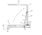
- FIG. 1 is a schematic explanatory view showing an example of an embodiment of a wing body according to the present invention.
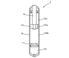
- FIG. 2 is a cross-sectional view showing an example of a gas shock absorber constituting the wing body according to the present invention.
- FIG. 3 is an enlarged plan view of a main part of the wing body shown in FIG.
- the wing body 1 is provided with a rectangular bottom plate 5 having a required length and width, side surfaces (not shown) provided on the left and right side surfaces of the bottom plate 5, and front and rear, as is apparent from FIG. It is composed of a hollow body main body 1a composed of a side surface 4 (not shown on the other side).
- the body main body 1a includes a center beam 14 disposed along the longitudinal direction in the upper center portion, and upper wings 2 and 2 that rotate in the vertical direction via a support shaft 6 disposed on the center beam 14. It consists of lower wings 3, 3 that are usually called “aori” that rotate in the vertical direction along a spindle (not shown) arranged on the bottom plate 5.
- the upper wings 2 and 2 are made of an aluminum material, so that weight reduction is achieved, and easy and smooth opening and closing is achieved manually.
- Each of the upper wings 2 has an upper wall 2a having a half width on the short side of the side face 4, and at least a half or more of left and right openings in the longitudinal direction of the body main body 1a.
- the side wall surface 2b can be closed.
- brackets 15 and 15 for attaching the tip of the gas shock absorber 7 are attached to the inner side surface of the upper surface wall 2a constituting each upper wing 2, respectively.
- the base end portion in the longitudinal direction of the upper surface wall 2a constituting the upper wing 2 is pivotally supported by a support shaft 6 disposed along the center beam 14.
- the upper wings 2 and 2 are pivotally supported by the center beam 14 by the support shaft 6 so as to be rotatable in the vertical direction.
- the upper wings 2 and 2 may be provided on both sides of the center beam 14 via support shafts.
- the upper portion of the body main body 1a functions as a rotation support device to urge the upper wing 2 in the opening direction.
- a base end portion of the gas shock absorber 7 having the above is attached via a bracket 16. Accordingly, the upper wings 2 and 2 are lifted upward to a required angle with the support shaft 6 as a fulcrum by the upward biasing force of the gas shock absorber 7.
- the same effect can be obtained by attaching the distal end portion of the gas shock absorber 7 to the wing body 1 via the bracket 15 and attaching the proximal end portion thereof via the bracket 16. It may be.
- the gas shock absorber 7 has a function of absorbing and attenuating vibration energy and kinetic energy using resistance when high-pressure gas flows.
- gas shock absorber in which high pressure gas (for example, nitrogen gas) and damper oil are enclosed is used.
- FIG. 2 is a cross-sectional view showing an example of a gas shock absorber 7 used in the wing body 1 according to the present invention.
- the gas shock absorber 7 is mainly composed of a bottomed cylindrical cylinder having a required diameter and length, and a free piston 11 is disposed inside the gas shock absorber 7.
- a gas chamber 13 filled with a high-pressure gas such as nitrogen gas is provided between them.
- the pressure of the gas chamber 13 is the distance from the center of the support shaft 6 on which the end of the upper wing 2 on the center beam 14 side is supported to the base end of the cylinder 8 of the gas shock absorber 7;
- the optimum value is determined based on the angle of the gas shock absorber 7. When the angle is large, the opening / closing operation is facilitated, and the height of the inside of the box is lowered.
- the gas shock absorber 7 preferably has an urging force that is substantially balanced with the load acting on the upper wing during opening and closing. Therefore, the pressure of the gas chamber 13 is preferably set to a pressure of 60 to 62 bar at a temperature of 28 ° C.
- the gas shock absorber 7 is provided such that its base end is positioned about 20 mm downward from the center of the support shaft 6 and about 140 mm outward. Since the gas shock absorber 7 is provided so as to incline upward at an angle of 3.5 to 5.5 °, the upper wing 2 rises with a small injection pressure and is positioned at an angle of 30 to 45 °. It comes to stop at. Therefore, when the opening operation of the upper wing 2 is performed, the gas shock absorber 7 urges the upper wing 2 in the opening operation direction, so that a force required for the opening operation is reduced. Further, when the upper wing 2 is closed from the fully opened state, the upper wing 2 is slowly closed to the predetermined angle position by the damping function of the gas shock absorber 7.
- the upper wing 2 may be attached at an angle of 30 to 60 °.
- an oil chamber 12 filled with oil as a damping medium is formed between the free piston 11 and the opening of the cylinder 8.
- a piston rod 9 is inserted into the cylinder 8 on the opening side of the cylinder 8 so as to freely advance and retract (extend / contract), and a piston 10 is provided at the insertion tip.
- the piston 10 is made of a disk-shaped member, and slides in the cylinder 8 as the piston rod 9 moves forward and backward.
- the piston 10 divides the oil chamber 12 into an upper oil chamber 12a and a lower oil chamber 12b.
- an oil passage 10a (orifice) having a relatively small flow area communicating with these oil chambers is provided. Is formed. Note that one or a plurality of the oil passages 10a may be formed. That is, it is divided into one that allows oil movement from the upper oil chamber 12a to the lower oil chamber 12b and one that allows oil movement from the lower oil chamber 10b to the upper oil chamber 10a. May be.
- the upper wing 2 rotates in the closing direction, the upper wing 2 rotates against the gas pressure in the gas chamber 13 of the gas shock absorber 7. At this time, since the weight of the upper wing 2 also acts, it can be manually rotated without requiring a large force. Since the oil passage 10a is formed so that the flow passage area is relatively narrow, a damping force is generated due to the fluid resistance when passing through the narrow flow passage, and the upper wing 2 is It can be closed slowly.
- the gas shock absorber 7 Since the gas shock absorber 7 has an excellent damping function, it works effectively and reliably even if the upper wing 2 is heavy, but the upper wing 2 is made of a lightweight material such as an aluminum material. By configuring, manual opening and closing of the upper wing 2 becomes easier and smoother.
- the wing body 1 of the present invention having such a configuration is configured to support the rotation of the upper wing 2 only by the gas shock absorber 7, a drive mechanism for opening and closing (rotating) the upper wing 2 is greatly improved. It can be simplified and made compact, and the cost can be reduced.
- the gas shock absorber 7 does not require the use of a drive source (a pump incorporating an oil tank and a gear), which is essential for a drive device composed of a hydraulic cylinder, and opens and closes the upper wing 2. It can be done manually. Therefore, the possibility of malfunction such as failure or running out of oil is extremely low, and the occurrence of oil leakage accidents is extremely low. Even if the gas shock absorber 7 breaks down, it can be quickly dealt with by replacing the gas shock absorber together, and repair is easy.
- a drive source a pump incorporating an oil tank and a gear
- the gas shock absorber 7 having such an action may be disposed in a pair on the left and right sides of the wing body 1 at a predetermined position (upper end portion of the side surface) of the side surfaces 4 and 4.
- the wing body 1 is disposed on both the front and rear side surfaces 4 and 4.
- the side surface 4 arranged on the rear side is a portal frame, and a pair of doors that are opened and closed to the left and right are mounted.
- the lower wing 3 is composed of side surfaces other than the side wall surface 2b constituting the upper wing 2, and is rotatably attached to both longitudinal edges of the bottom plate 5 of the body main body 1a via hinges. ing.
- the lower wing 3 When the lower wing 3 is opened, the lower wing 3 can be opened at an angle of approximately 180 ° by rotating the lower wing 3 downward. On the other hand, when the lower wing 3 is closed, it is lifted while rotating the front edge of the lower wing 3 upward.
- the left and right side surfaces of the wing body 1 are divided into an upper wing 2 whose upper part is integrated with a part of the upper wall 2a, and a lower wing 3 that is freely opened and closed along the side edge of the bottom plate 5. It was explained in the form of However, there is no limitation on the specific structure of the wing body 1 as long as the left and right side surfaces are opened simultaneously or at least one of the left and right side surfaces along the longitudinal direction is opened. .
- the gas shock absorber 7 is applied to the wing body 1 .
- the present invention can also be applied to various wing type packing boxes such as containers other than the wing body.
- the wing body opening / closing method and apparatus according to the present invention has an extremely simple structure because a gas shock absorber is interposed between the upper wing and the wing body so that the upper wing can be easily and smoothly opened and closed manually. Therefore, it can be loaded and unloaded at any time because there are few breakdowns, and it is widely used in the transportation industry.
Landscapes
- Engineering & Computer Science (AREA)
- Mechanical Engineering (AREA)
- Chemical & Material Sciences (AREA)
- Combustion & Propulsion (AREA)
- Transportation (AREA)
- Fluid-Damping Devices (AREA)
Abstract
La présente invention concerne : un procédé d'ouverture/fermeture de carrosserie de camionnette de type aile qui permet qu'une charge initiale soit réduite au minimum lorsqu'une aile supérieure est ouverte et fermée et qui permet son ouverture et sa fermeture manuelle ; et une carrosserie de camionnette comprenant un dispositif pour ledit procédé. Un amortisseur à gaz (7) est agencé entre l'extrémité d'une aile supérieure (2) et une carrosserie (1) de camionnette qui supporte de manière pivotante l'aile supérieure (2) de sorte que l'aile supérieure (2) puisse tourner. Ainsi, lorsque l'aile supérieure (2) pivote vers le haut, l'amortisseur à gaz (7) agit de sorte à assister le pivotement vers le haut de l'aile supérieure (2).
Priority Applications (1)
| Application Number | Priority Date | Filing Date | Title |
|---|---|---|---|
| PCT/JP2015/070031 WO2017009930A1 (fr) | 2015-07-13 | 2015-07-13 | Procédé d'ouverture/fermeture de carrosserie d'aile et carrosserie d'aile |
Applications Claiming Priority (1)
| Application Number | Priority Date | Filing Date | Title |
|---|---|---|---|
| PCT/JP2015/070031 WO2017009930A1 (fr) | 2015-07-13 | 2015-07-13 | Procédé d'ouverture/fermeture de carrosserie d'aile et carrosserie d'aile |
Publications (1)
| Publication Number | Publication Date |
|---|---|
| WO2017009930A1 true WO2017009930A1 (fr) | 2017-01-19 |
Family
ID=57757136
Family Applications (1)
| Application Number | Title | Priority Date | Filing Date |
|---|---|---|---|
| PCT/JP2015/070031 Ceased WO2017009930A1 (fr) | 2015-07-13 | 2015-07-13 | Procédé d'ouverture/fermeture de carrosserie d'aile et carrosserie d'aile |
Country Status (1)
| Country | Link |
|---|---|
| WO (1) | WO2017009930A1 (fr) |
Citations (2)
| Publication number | Priority date | Publication date | Assignee | Title |
|---|---|---|---|---|
| JPS59121232U (ja) * | 1983-02-05 | 1984-08-15 | 山田車体工業株式会社 | 屋根開閉式車両の防雨構造 |
| JPH01158319U (fr) * | 1988-04-22 | 1989-11-01 |
-
2015
- 2015-07-13 WO PCT/JP2015/070031 patent/WO2017009930A1/fr not_active Ceased
Patent Citations (2)
| Publication number | Priority date | Publication date | Assignee | Title |
|---|---|---|---|---|
| JPS59121232U (ja) * | 1983-02-05 | 1984-08-15 | 山田車体工業株式会社 | 屋根開閉式車両の防雨構造 |
| JPH01158319U (fr) * | 1988-04-22 | 1989-11-01 |
Similar Documents
| Publication | Publication Date | Title |
|---|---|---|
| JP5590478B1 (ja) | ウイング型コンテナの開閉方法およびその装置 | |
| US8226146B2 (en) | Tailgate dampening system | |
| US20130036673A1 (en) | Container or vehicle body with side door and a side door drive unit | |
| US20090189406A1 (en) | Tailgate lift assistor | |
| KR20190057007A (ko) | 차량의 운송용 컨테이너 | |
| KR20150129434A (ko) | 중량물 상,하차용 화물차의 리프트장치 | |
| CN207404275U (zh) | 一种上开门铁路运输集装箱 | |
| US7854092B2 (en) | Mezzanine gate system | |
| CN210028719U (zh) | 集装箱 | |
| RU2010130475A (ru) | Транспортная единица с ориентирующим устройством для автомобиля | |
| JP6531199B1 (ja) | オーバーヘッドドア | |
| US10871017B2 (en) | Motor vehicle having a manual rear closure member | |
| CN208763731U (zh) | 一种改进型叉车排气管防雨帽结构 | |
| KR100980669B1 (ko) | 윙바디 개폐 장치 | |
| CN101397036B (zh) | 翼开启厢体及具有该厢体的运输车与集装箱 | |
| KR100808048B1 (ko) | 윙바디 차량의 측면게이트 고정구조 | |
| CN112009344B (zh) | 一种物料运输设备 | |
| KR102680073B1 (ko) | 적재함 높이 가변형 탑차 | |
| KR101537003B1 (ko) | 화물차 적재함 도어 개폐장치 | |
| CN110589260B (zh) | 开盖结构及具有其的集装箱 | |
| JP7569852B2 (ja) | 自動装填用遠心分離機 | |
| JP2020139290A (ja) | 車両ドア開閉装置 | |
| CN211309571U (zh) | 开盖结构及具有其的集装箱 | |
| NL2006822C2 (nl) | Mobiele tankcontainer. | |
| JP2006513077A (ja) | 旋回可能な車両ウィンドウワイパーの駆動機構 |
Legal Events
| Date | Code | Title | Description |
|---|---|---|---|
| 121 | Ep: the epo has been informed by wipo that ep was designated in this application |
Ref document number: 15898243 Country of ref document: EP Kind code of ref document: A1 |
|
| NENP | Non-entry into the national phase |
Ref country code: DE |
|
| NENP | Non-entry into the national phase |
Ref country code: JP |
|
| 122 | Ep: pct application non-entry in european phase |
Ref document number: 15898243 Country of ref document: EP Kind code of ref document: A1 |