WO2017009985A1 - Palette - Google Patents
Palette Download PDFInfo
- Publication number
- WO2017009985A1 WO2017009985A1 PCT/JP2015/070306 JP2015070306W WO2017009985A1 WO 2017009985 A1 WO2017009985 A1 WO 2017009985A1 JP 2015070306 W JP2015070306 W JP 2015070306W WO 2017009985 A1 WO2017009985 A1 WO 2017009985A1
- Authority
- WO
- WIPO (PCT)
- Prior art keywords
- pallet
- hole
- leg
- pallet according
- beam portion
- Prior art date
- Legal status (The legal status is an assumption and is not a legal conclusion. Google has not performed a legal analysis and makes no representation as to the accuracy of the status listed.)
- Ceased
Links
Images






Classifications
-
- Y—GENERAL TAGGING OF NEW TECHNOLOGICAL DEVELOPMENTS; GENERAL TAGGING OF CROSS-SECTIONAL TECHNOLOGIES SPANNING OVER SEVERAL SECTIONS OF THE IPC; TECHNICAL SUBJECTS COVERED BY FORMER USPC CROSS-REFERENCE ART COLLECTIONS [XRACs] AND DIGESTS
- Y02—TECHNOLOGIES OR APPLICATIONS FOR MITIGATION OR ADAPTATION AGAINST CLIMATE CHANGE
- Y02W—CLIMATE CHANGE MITIGATION TECHNOLOGIES RELATED TO WASTEWATER TREATMENT OR WASTE MANAGEMENT
- Y02W30/00—Technologies for solid waste management
- Y02W30/50—Reuse, recycling or recovery technologies
- Y02W30/80—Packaging reuse or recycling, e.g. of multilayer packaging
Definitions
- the present invention relates to the structure of a pallet that is used for loading and transporting articles in logistics or the like.
- a forklift work is performed in which a fork of a forklift is inserted into a pallet and lifted to load the product and the pallet together on a loading platform such as a truck.
- FIG. 10 is a schematic front view of a conventional general wooden pallet.
- FIG. 11 is a schematic plan view of the wooden pallet of FIG.
- the wooden pallet 300 includes a lower plate 202 on a flat plate, leg portions 200 provided at both left and right ends of the upper portion of the lower plate 202, and an upper plate 201 provided so as to bridge the left and right leg portions 200. It is configured.
- the lower plate 202, the leg 200, and the upper plate 201 are fixed by a nail 203 or the like.
- a pallet in which the pallet can be disassembled and replaced by attaching and removing the binding band without fixing the upper plate and legs constituting the pallet with nails, but with a binding band (for example, patents).
- Reference 2 a binding band
- the pallet proposed in Patent Document 1 has a shock absorbing material that absorbs shock, but disassembly and replacement of the pallet are not considered, and it is difficult to disassemble the pallet. There was a problem that it could not be recycled effectively.
- the present invention has been made to solve the above-described problems, and an object thereof is to obtain a pallet that is easy to recycle and has excellent durability.
- the pallet according to the present invention includes a plurality of leg portions each having a plurality of through holes, and a plurality of beam portions inserted into the through holes, wherein the beam portions are inserted into the through holes.
- a gap is formed below the beam portion.
- a pallet that is easy to recycle and has excellent durability can be obtained by including a plurality of leg portions having a plurality of through holes and a plurality of beam portions inserted into the through holes.
- FIG. 1 is a schematic plan view of a pallet according to Embodiment 1 of the present invention.
- FIG. 2 is a schematic front view of the pallet according to Embodiment 1 of the present invention.
- FIG. 3 is a schematic right side view of the pallet according to Embodiment 1 of the present invention.
- the pallet 100 is composed of four leg portions 1 and four beam portions 2.
- a through hole 1 b that penetrates from one side surface of the leg portion 1 to the opposite side surface is provided in the surface portion of the upper surface of the leg portion 1.
- the lattice part pallet 100 as shown in FIG. 1 is comprised by inserting the beam part 2 in the through-hole 1b.
- the pallet 100 shown in FIG. 1 is used for transporting heavy objects such as an outdoor unit, an indoor unit, a compressor, and a blower of an air conditioner.
- the present invention is not limited to this, and the leg portion 1 and It is sufficient that there are at least two beam portions 2 each. The same applies to the second embodiment described later.
- the through-hole 1b is provided on the upper surface side of the leg 1 and the beam 2 is inserted into the through-hole 1b, so that a gap 1a is formed below the beam 2.
- a heavy product such as a large outdoor unit is placed on the pallet 100 and transported by a forklift
- the fork (not shown) of the forklift is inserted into the gap 1a.
- the fork is hooked on the beam portion 2 to lift the pallet 100 and move the pallet 100 to a truck or the like.
- the material of the leg portion 1 of the pallet 100 is made of a shock-absorbing rubber material, an elastic synthetic resin, or an elastic foamed resin, so that vibration can be absorbed and the load on the product can be reduced. It becomes possible.
- the material of the beam portion 2 is made of metal, wood, hard plastic or the like having such a strength that the fork can be hooked and the pallet 100 on which the product is placed can be lifted.
- FIG. 4 is a schematic cross-sectional view of the through hole of the pallet according to Embodiment 1 of the present invention.
- an arc-shaped through hole 1 b is provided in the surface portion on the upper surface side of the leg portion 1.
- a protrusion 1d and a protrusion 1e are formed in the through hole 1b provided on the front surface side of the leg 1. That is, the through hole 1 b is formed at a position where a part of the through hole 1 b is exposed on the upper surface of the leg portion 1.
- the width of the opening formed on the upper surface of the through hole 1b is, for example, the maximum of the beam portion 2 configured in a round bar shape.
- the length is large, that is, 70 to 90% of the diameter.
- the beam part 2 inserted into the through hole 1b in a state where the leg part 1 is elastically deformed is tightened, and the beam part 2 is fixed to the leg part 1.
- the beam portion 2 has a round bar shape.
- the present invention is not limited to this, and the quadrangular shape or the quadrangular shape as shown in FIGS. 5 and 6 to be described later. Other polygonal shapes may be used.
- the operation of lifting the pallet 100 and the operation after using the pallet 100 will be described with reference to FIGS.
- the fork (not shown) of the forklift is inserted into the gap 1a, and the fork is hooked on the beam 2 and lifted.
- the diameter of the through hole 1b of the leg portion 1 is smaller than the diameter of the beam portion 2, and the beam portion 2 is fastened by the through hole 1b. Therefore, the beam portion 2 and the leg portion 1 may be displaced. Absent.
- the width of the surface gap portion 1c is smaller than the diameter of the beam portion 2, even if the fork is hooked on the beam portion 2 and the pallet 100 is lifted, the leg portion 1 does not come off the pallet 100.
- the positions of the leg portions 1 are arranged at intervals so as not to interfere with the forks before placing the product on the pallet 100. However, even when the size of the fork or the like is unexpected and the leg 1 and the fork interfere with each other, the pallet 100 is slightly lifted up to create a gap between the leg 1 and the ground. The position of the part 1 can be adjusted. In addition, when the transportation of the product is finished and the pallet 100 is withdrawn, the beam part 2 is removed from the leg part 1 to disassemble the pallet 100 into two types of parts and collect the pallet 100 in a space-saving and compact manner. be able to.
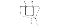
- FIG. 5 is a schematic cross-sectional view of another shape of the through hole of the pallet according to Embodiment 1 of the present invention.
- the shape of the through hole 1 j of the leg part 1 is made to be a rectangle according to the shape of the beam part 2. May be.
- the projection 1f and the projection 1g are provided on the surface of the leg 1 so that the beam 2 does not come out of the through hole 1j, and the beam 2 is hooked. By doing in this way, the beam part 2 can be fixed to the leg part 1.
- FIG. 5 is a schematic cross-sectional view of another shape of the through hole of the pallet according to Embodiment 1 of the present invention.
- FIG. 6 is a schematic sectional view of another shape of the through hole of the pallet according to Embodiment 1 of the present invention.
- the shape of the through hole 1 k of the leg part 1 may be a quadrangle.
- the protrusion 1h and the protrusion 1i are provided on the inner wall portion of the through hole 1k so that the beam portion 2 does not come out of the through hole 1k, and the recess (not shown) is also provided on the beam portion 2, thereby providing the protrusion 1h and the protrusion 1i. Is engaged with the concave portion of the beam portion 2. By doing in this way, the beam part 2 can be fixed to the leg part 1.
- FIG. 7 shows a combination example of the leg portion and the beam portion of the pallet according to the first embodiment of the present invention.
- the legs 1 can be arranged in a staggered manner to change the shape of the pallet 100a. In this way, it is possible to change the shape of the pallet 100a using the same leg 1 and beam 2.
- the beam portion 2 includes the plurality of leg portions each having the plurality of through holes 1b and the plurality of beam portions 2 inserted into the through holes 1b.
- the pallet 100 which has the intensity
- the pallet 100 which has recyclability and the compactness at the time of collection
- the through hole 1b has a surface gap portion 1c on the surface portion of the leg portion 1, and the width of the surface gap portion 1c is 70 to 90% of the width of the beam portion 2.
- leg part 1 holds the beam part 2 inserted in the through hole 1b in an elastically deformed state. By doing so, the beam portion 2 is fastened to the through hole 1 b and fixed to the leg portion 1.
- the leg 1 is formed of a rubber material, an elastic synthetic resin, or an elastic foamed resin. By doing in this way, it becomes possible for the pallet 100 to absorb the vibration caused by transportation or the like and to reduce the load on the product.
- the beam portion 2 is formed of metal, wood or hard plastic. By doing in this way, also when lifting the pallet 100 on which the product which is a heavy article is lifted, the pallet 100 can be lifted by hooking the fork to the beam part 2 without damaging the beam part 2.
- Embodiment 2 Since the basic configuration of the pallet in the second embodiment is the same as that of the pallet in the first embodiment, the second embodiment will be described below with a focus on differences from the first embodiment.
- the difference between the first embodiment and the second embodiment is that a through hole is provided inside the leg portion.
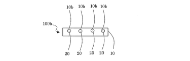
- FIG. 8 is a schematic right side view of the pallet according to the second embodiment of the present invention.
- FIG. 9 is a schematic front view of a pallet according to Embodiment 2 of the present invention.
- the pallet 100 b is composed of the leg portion 10 and the beam portion 20. Further, a plurality of through holes 10b are provided at positions on the upper side of the leg portion 10 of the pallet 100b and not exposed on the upper surface of the leg portion 10. The beam portion 20 is inserted into the through hole 10b. A gap portion 10 a is formed at the lower portion of the beam portion 20.
- the fork of the forklift lifts the pallet 100b by being hooked on the beam portion 20.
- the weight of the product placed on the pallet 100b is received by the leg 10 formed of a rubber material, an elastic synthetic resin, or an elastic foamed resin.
- the through hole 1b is formed at a position on the upper side of the leg 1 and not exposed on the upper surface.
Landscapes
- Pallets (AREA)
Abstract
La présente invention concerne un palette recyclable présentant une excellente durabilité. La palette comprend une pluralité de jambes ayant chacune une pluralité de trous traversants; et une pluralité de parties formant poutres qui sont insérées dans les trous traversants. Dans un état où les parties formant poutres ont été insérées dans les trous traversants, un espace est formé au niveau de la partie inférieure des parties formant poutres.
Priority Applications (1)
| Application Number | Priority Date | Filing Date | Title |
|---|---|---|---|
| PCT/JP2015/070306 WO2017009985A1 (fr) | 2015-07-15 | 2015-07-15 | Palette |
Applications Claiming Priority (1)
| Application Number | Priority Date | Filing Date | Title |
|---|---|---|---|
| PCT/JP2015/070306 WO2017009985A1 (fr) | 2015-07-15 | 2015-07-15 | Palette |
Publications (1)
| Publication Number | Publication Date |
|---|---|
| WO2017009985A1 true WO2017009985A1 (fr) | 2017-01-19 |
Family
ID=57757914
Family Applications (1)
| Application Number | Title | Priority Date | Filing Date |
|---|---|---|---|
| PCT/JP2015/070306 Ceased WO2017009985A1 (fr) | 2015-07-15 | 2015-07-15 | Palette |
Country Status (1)
| Country | Link |
|---|---|
| WO (1) | WO2017009985A1 (fr) |
Citations (6)
| Publication number | Priority date | Publication date | Assignee | Title |
|---|---|---|---|---|
| JPS5018295Y1 (fr) * | 1968-08-21 | 1975-06-04 | ||
| JPS63502025A (ja) * | 1985-12-19 | 1988-08-11 | アツテルビイ,フレツド | パレット、基礎部材およびこれに対する管 |
| JPH0577029U (ja) * | 1992-03-31 | 1993-10-19 | 鐘淵化学工業株式会社 | 通いパレット |
| JPH0582829U (ja) * | 1992-04-16 | 1993-11-09 | 鐘淵化学工業株式会社 | 通いパレット |
| US5685233A (en) * | 1996-07-31 | 1997-11-11 | Milbe Products, Inc. | Recyclable pallet assembly |
| JP2000508607A (ja) * | 1997-02-03 | 2000-07-11 | ビタル,アントワーヌ | 荷役用パレット |
-
2015
- 2015-07-15 WO PCT/JP2015/070306 patent/WO2017009985A1/fr not_active Ceased
Patent Citations (6)
| Publication number | Priority date | Publication date | Assignee | Title |
|---|---|---|---|---|
| JPS5018295Y1 (fr) * | 1968-08-21 | 1975-06-04 | ||
| JPS63502025A (ja) * | 1985-12-19 | 1988-08-11 | アツテルビイ,フレツド | パレット、基礎部材およびこれに対する管 |
| JPH0577029U (ja) * | 1992-03-31 | 1993-10-19 | 鐘淵化学工業株式会社 | 通いパレット |
| JPH0582829U (ja) * | 1992-04-16 | 1993-11-09 | 鐘淵化学工業株式会社 | 通いパレット |
| US5685233A (en) * | 1996-07-31 | 1997-11-11 | Milbe Products, Inc. | Recyclable pallet assembly |
| JP2000508607A (ja) * | 1997-02-03 | 2000-07-11 | ビタル,アントワーヌ | 荷役用パレット |
Similar Documents
| Publication | Publication Date | Title |
|---|---|---|
| US9139334B2 (en) | Pallet and method for using the pallet | |
| US9284107B2 (en) | Pallet dampening system | |
| KR101222932B1 (ko) | 조립식 팔레트 | |
| US20140251189A1 (en) | Pallet with support elements configured as one-piece skids and related methods | |
| KR200464149Y1 (ko) | 파렛트 적재 랙 | |
| KR100983828B1 (ko) | 철재 팔레트 | |
| US20150210425A1 (en) | All wooden half pallet | |
| US9032884B2 (en) | Pallet | |
| KR200485420Y1 (ko) | 롤 타입 화물 운송용 거치장치 | |
| EP3116799A1 (fr) | Raccord de bord pour supporter et protéger une caisse de chargement | |
| KR101665005B1 (ko) | 조립형 금속 팔레트 | |
| KR101171138B1 (ko) | 조립식 파렛트 | |
| KR20110051436A (ko) | 파렛트 | |
| WO2017009985A1 (fr) | Palette | |
| KR101252180B1 (ko) | 조립식 철재 팔레트 | |
| KR101612531B1 (ko) | 철재 파렛트 | |
| KR102268782B1 (ko) | 탄성끼움방식을 이용하여 체결되는 강재 스키드 | |
| KR20100006348U (ko) | 우레탄 완충부재를 구비하는 운반용 파레트 | |
| KR101821149B1 (ko) | 파렛트 | |
| KR20110051431A (ko) | 파렛트 | |
| CA3039439C (fr) | Palette en carton recyclable | |
| KR101589283B1 (ko) | 철재 파렛트 | |
| KR20150061803A (ko) | 철재 파렛트 | |
| KR20160041186A (ko) | 금속 파렛트 | |
| KR102001872B1 (ko) | 운송용 박스 |
Legal Events
| Date | Code | Title | Description |
|---|---|---|---|
| 121 | Ep: the epo has been informed by wipo that ep was designated in this application |
Ref document number: 15898297 Country of ref document: EP Kind code of ref document: A1 |
|
| NENP | Non-entry into the national phase |
Ref country code: DE |
|
| NENP | Non-entry into the national phase |
Ref country code: JP |
|
| 122 | Ep: pct application non-entry in european phase |
Ref document number: 15898297 Country of ref document: EP Kind code of ref document: A1 |