WO2017010033A1 - 放射線画像撮影装置 - Google Patents
放射線画像撮影装置 Download PDFInfo
- Publication number
- WO2017010033A1 WO2017010033A1 PCT/JP2016/002483 JP2016002483W WO2017010033A1 WO 2017010033 A1 WO2017010033 A1 WO 2017010033A1 JP 2016002483 W JP2016002483 W JP 2016002483W WO 2017010033 A1 WO2017010033 A1 WO 2017010033A1
- Authority
- WO
- WIPO (PCT)
- Prior art keywords
- radiation source
- main body
- radiographic imaging
- wheel
- arm
- Prior art date
- Legal status (The legal status is an assumption and is not a legal conclusion. Google has not performed a legal analysis and makes no representation as to the accuracy of the status listed.)
- Ceased
Links
Images










Classifications
-
- A—HUMAN NECESSITIES
- A61—MEDICAL OR VETERINARY SCIENCE; HYGIENE
- A61B—DIAGNOSIS; SURGERY; IDENTIFICATION
- A61B6/00—Apparatus or devices for radiation diagnosis; Apparatus or devices for radiation diagnosis combined with radiation therapy equipment
- A61B6/44—Constructional features of apparatus for radiation diagnosis
- A61B6/4405—Constructional features of apparatus for radiation diagnosis the apparatus being movable or portable, e.g. handheld or mounted on a trolley
-
- A—HUMAN NECESSITIES
- A61—MEDICAL OR VETERINARY SCIENCE; HYGIENE
- A61B—DIAGNOSIS; SURGERY; IDENTIFICATION
- A61B6/00—Apparatus or devices for radiation diagnosis; Apparatus or devices for radiation diagnosis combined with radiation therapy equipment
- A61B6/42—Arrangements for detecting radiation specially adapted for radiation diagnosis
-
- A—HUMAN NECESSITIES
- A61—MEDICAL OR VETERINARY SCIENCE; HYGIENE
- A61B—DIAGNOSIS; SURGERY; IDENTIFICATION
- A61B6/00—Apparatus or devices for radiation diagnosis; Apparatus or devices for radiation diagnosis combined with radiation therapy equipment
- A61B6/42—Arrangements for detecting radiation specially adapted for radiation diagnosis
- A61B6/4208—Arrangements for detecting radiation specially adapted for radiation diagnosis characterised by using a particular type of detector
-
- A—HUMAN NECESSITIES
- A61—MEDICAL OR VETERINARY SCIENCE; HYGIENE
- A61B—DIAGNOSIS; SURGERY; IDENTIFICATION
- A61B6/00—Apparatus or devices for radiation diagnosis; Apparatus or devices for radiation diagnosis combined with radiation therapy equipment
- A61B6/42—Arrangements for detecting radiation specially adapted for radiation diagnosis
- A61B6/4283—Arrangements for detecting radiation specially adapted for radiation diagnosis characterised by a detector unit being housed in a cassette
-
- A—HUMAN NECESSITIES
- A61—MEDICAL OR VETERINARY SCIENCE; HYGIENE
- A61B—DIAGNOSIS; SURGERY; IDENTIFICATION
- A61B6/00—Apparatus or devices for radiation diagnosis; Apparatus or devices for radiation diagnosis combined with radiation therapy equipment
- A61B6/44—Constructional features of apparatus for radiation diagnosis
-
- A—HUMAN NECESSITIES
- A61—MEDICAL OR VETERINARY SCIENCE; HYGIENE
- A61B—DIAGNOSIS; SURGERY; IDENTIFICATION
- A61B6/00—Apparatus or devices for radiation diagnosis; Apparatus or devices for radiation diagnosis combined with radiation therapy equipment
- A61B6/44—Constructional features of apparatus for radiation diagnosis
- A61B6/4429—Constructional features of apparatus for radiation diagnosis related to the mounting of source units and detector units
-
- A—HUMAN NECESSITIES
- A61—MEDICAL OR VETERINARY SCIENCE; HYGIENE
- A61B—DIAGNOSIS; SURGERY; IDENTIFICATION
- A61B6/00—Apparatus or devices for radiation diagnosis; Apparatus or devices for radiation diagnosis combined with radiation therapy equipment
- A61B6/44—Constructional features of apparatus for radiation diagnosis
- A61B6/4429—Constructional features of apparatus for radiation diagnosis related to the mounting of source units and detector units
- A61B6/4452—Constructional features of apparatus for radiation diagnosis related to the mounting of source units and detector units the source unit and the detector unit being able to move relative to each other
-
- A—HUMAN NECESSITIES
- A61—MEDICAL OR VETERINARY SCIENCE; HYGIENE
- A61B—DIAGNOSIS; SURGERY; IDENTIFICATION
- A61B6/00—Apparatus or devices for radiation diagnosis; Apparatus or devices for radiation diagnosis combined with radiation therapy equipment
- A61B6/44—Constructional features of apparatus for radiation diagnosis
- A61B6/4429—Constructional features of apparatus for radiation diagnosis related to the mounting of source units and detector units
- A61B6/4458—Constructional features of apparatus for radiation diagnosis related to the mounting of source units and detector units the source unit or the detector unit being attached to robotic arms
-
- A—HUMAN NECESSITIES
- A61—MEDICAL OR VETERINARY SCIENCE; HYGIENE
- A61B—DIAGNOSIS; SURGERY; IDENTIFICATION
- A61B6/00—Apparatus or devices for radiation diagnosis; Apparatus or devices for radiation diagnosis combined with radiation therapy equipment
- A61B6/56—Details of data transmission or power supply, e.g. use of slip rings
-
- B—PERFORMING OPERATIONS; TRANSPORTING
- B60—VEHICLES IN GENERAL
- B60B—VEHICLE WHEELS; CASTORS; AXLES FOR WHEELS OR CASTORS; INCREASING WHEEL ADHESION
- B60B33/00—Castors in general ; Anti-clogging castors
- B60B33/0078—Castors in general ; Anti-clogging castors characterised by details of the wheel braking mechanism
- B60B33/0081—Castors in general ; Anti-clogging castors characterised by details of the wheel braking mechanism acting on tyre tread
-
- G—PHYSICS
- G01—MEASURING; TESTING
- G01T—MEASUREMENT OF NUCLEAR OR X-RADIATION
- G01T1/00—Measuring X-radiation, gamma radiation, corpuscular radiation, or cosmic radiation
- G01T1/16—Measuring radiation intensity
- G01T1/161—Applications in the field of nuclear medicine, e.g. in vivo counting
Definitions
- the present invention relates to a radiographic image capturing device, and more particularly to a radiographic image capturing device in which a radiation source is supported on an arm or the like.
- Patent Document 1 Conventionally, for example, as disclosed in Patent Document 1 and Non-Patent Document 1, only the minimum components for radiation irradiation, such as a radiation source and an electric circuit, are mounted and can be operated by an operator by hand.
- a portable radiation irradiation apparatus has been proposed. This type of portable radiation irradiation apparatus is light enough to be held and operated by an operator, and is advantageous for photographing a subject from various directions.
- a storage phosphor sheet IP: ImagingIPlate
- an X-ray silver salt film is usually stored in the casing.
- a cassette is used. That is, if such a cassette is placed at a position facing the radiation irradiating apparatus with the subject in between, and the radiation irradiating apparatus is driven in this state, radiation such as X-rays transmitted through the subject is contained in the cassette.
- the stimulable phosphor sheet or the like is irradiated, and a transmitted radiation image of the subject is recorded on the stimulable phosphor sheet or the like.
- Patent Document 2 shows an example of this electronic cassette.
- Non-Patent Document 1 also shows an example of such a support device, and in particular, a support device that can travel by providing a wheel portion at the lower part of a leg.
- a radiographic imaging device that combines the above-described support device that can travel and a portable radiation irradiation device can easily shoot a subject from various directions and also has mobility. It is suitable for use in emergency rooms.
- Patent Document 3 and Patent Document 4 a radiographic imaging apparatus in which a radiation source is attached to an arm unit for use is also known.
- this type of radiographic imaging apparatus basically includes a leg portion, a main body portion that houses a battery for driving the radiation source and an electric circuit for driving the radiation source and is held on the leg portion.
- the arm unit connected to the main body unit and the radiation source attached to the arm unit are provided.
- the radiographic imaging device having the above basic configuration can be easily transported in a narrow place, and can be used even in an environment where an AC power source cannot be used, so that it can be transported to an emergency in a medical institution such as a hospital. It is particularly preferably used for taking radiographs of a patient who has been in bed or a patient sleeping in a narrow bed.
- Non-Patent Document 1 that is, a radiographic image capturing apparatus in which a traveling support device and a portable radiation irradiation apparatus are combined, and Patent Document 3 and Patent Document 4 are used. None of the radiographic image capturing apparatuses shown in FIG. 1 has a small turn, so that there is still room for improvement in carrying quickly to a use position through a narrow place.
- the present invention has been made in view of the above circumstances, and an object of the present invention is to provide a radiographic image capturing apparatus that can be turned quickly and can be quickly transported to a use position.
- a first radiographic image capturing apparatus includes: A leg portion having three or more wheel portions, and capable of running on the device mounting surface with the wheels; A main body held on the legs, A radiation source support unit composed of an arm unit and the like connected to the main body unit; A radiation source attached to the radiation source support; A battery that is housed in the body and drives the radiation source; In a radiographic imaging apparatus provided with a circuit that is housed in the main body and is involved in driving the radiation source, The wheel portion is composed of a turning caster.
- the second radiographic imaging device is: A leg portion having three or more wheel portions, and capable of running on the device mounting surface with the wheels; A main body held on the legs, A radiation source support connected to the body, A radiation source attached to the radiation source support; A battery that is housed in the body and drives the radiation source; In a radiographic imaging apparatus provided with a circuit that is housed in the main body and is involved in driving the radiation source, The wheel portion is composed of omnidirectional moving wheels.
- the omnidirectional moving wheel described above is horizontal when traveling, such as an omni wheel (registered trademark) or mecanum wheel disclosed in, for example, Japanese Patent Application Laid-Open No. 2010-076630 and Japanese Patent Application Laid-Open No. 2012-030735.
- the rotating body is composed of a rotating body that rotates around a rotating shaft that faces and a plurality of rollers that are attached to the rotating body so as to be along one circle coaxial with the rotating body, and the rotating body rotates. Accordingly, the first roller moves in the first direction, and the roller rotates to move in the second direction intersecting with the first direction.
- the term “horizontal” means that the leg is parallel to the apparatus mounting surface in a state where the legs are placed on the normally horizontal apparatus mounting surface.
- the rotation axis of the roller is set so as to extend in a tangential direction of one circle coaxial with the rotating body or a direction close thereto.
- the main body is rotatable relative to the leg around a rotation axis extending in the vertical direction,
- the radiation source support part consisting of an arm part etc. protrudes in one horizontal direction from the main body part,
- the main body has a shape in which a length in a direction parallel to the one direction is shorter than a length in a direction perpendicular to the one direction in a plan view.
- the above-mentioned “horizontal” means that, in the same manner as described above, it is parallel to the apparatus mounting surface in a state where the legs are placed on the normal horizontal apparatus mounting surface.
- the term “projecting in the horizontal direction” includes the fact that it projects obliquely with a horizontal component.
- the above-described “planar state” means a state when projected onto the apparatus mounting surface.
- the above-mentioned “length” indicates the maximum length, and when the side of the main body portion is inclined with respect to each direction, it similarly indicates the maximum length in one direction.
- the main body has a length in a direction parallel to the one direction in a plan view and a length in a direction perpendicular to the one direction. It is preferable that the shape is 1/3 or less.
- the radiographic imaging device of the present invention is in the above-described particularly desirable form, it is preferable that the main body portion is inclined so that the upper end is closer to the radiation source than the lower end.
- the main body unit is configured to accommodate a battery and a circuit related to driving of the radiation source in a substantially rectangular parallelepiped casing. preferable.
- the circuit related to driving of the radiation source is divided into a plurality of blocks, and all the plurality of blocks cross in the direction intersecting with the one direction. It is preferable that they are arranged side by side.
- the outermost end of the leg portion is located when the leg portion is turned so that at least two wheel portions follow a common circle on the device placement surface.
- the main body is all located within the circular trajectory.
- the “outermost end” of the leg portion is the outermost end in the radial direction of the circular locus, that is, the end portion located farthest in the radial direction from the center of the circular locus.
- this “outermost end” is not necessarily the outermost end of the wheel part. If there is a square base or the like that is attached to the lower surface and spreads outside the wheel part, the base etc. It may be the outermost end.
- the radiation source support portion is extendable.
- the radiation source is rotatable around an axis parallel to the longitudinal direction of the portion of the radiation source support portion to which the radiation source is attached. .
- the radiation source is oscillatable in a direction in which the elevation angle of the radiation output axis changes, and a oscillating position fixing means for fixing the oscillating position of the radiation source is provided. It is preferable that In particular, in the case of the above-described configuration, when the radiation source is released from the oscillating position fixed by the oscillating position fixing means, the radiation emission axis is directed downward as compared with the case where the radiation source is fixed by the action of its own weight. It is desirable to be configured to take the swing position.
- the wheel portion is provided with a brake means.
- a height adjusting mechanism capable of adjusting the height from the wheel portion to the radiation source support portion is further provided.
- the height adjusting mechanism as described above is constituted by the above-described leg portions that are adjustable in angle with respect to the horizontal direction.
- the height adjusting mechanism may be constituted by an extendable cylinder mechanism provided at least at a part between the wheel portion and the radiation source support portion.
- the height adjusting mechanism may be constituted by an elevating mechanism that elevates and lowers a portion connected to the radiation source support portion in the main body portion.
- the radiographic imaging device of the present invention can move in the front-rear and left-right directions, and can move so as to make a large curve, since the wheel portion is composed of a turning caster or an omnidirectional moving wheel. It is also possible to swivel (that is, to rotate around the body axis in the case of a human being), so that it can be quickly brought to the use position with a small turn.
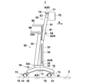
- the perspective view which shows the radiographic imaging apparatus by one Embodiment of this invention The side view which shows the state at the time of non-use of the radiographic imaging apparatus of FIG.
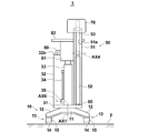
- the side view which shows the state at the time of use of the radiographic imaging apparatus of FIG. FIG. 1 is a rear view showing a state when the radiographic imaging apparatus of FIG. 1 is not used.
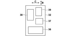
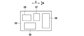
- FIG. 10 Schematic showing another example of the arrangement state of a plurality of circuits in the main body
- the perspective view which shows another example of the wheel part which can be applied to the radiographic imaging apparatus of this invention.
- the perspective view which shows the place which has the wheel part of FIG. 10 in another state.
- the side view which shows another example of the radiation source support part which can be applied to the radiographic imaging apparatus of this invention
- the perspective view which shows the front side of an electronic cassette
- the perspective view which shows the back side of an electronic cassette
- the perspective view which shows another example of the radiation source support part which can be applied to the radiographic imaging apparatus of this invention.
- FIG. 18 is a side view illustrating an example of a usage state of the radiographic image capturing apparatus of FIG.
- FIG. 18 is a plan view showing a part of the radiographic apparatus of FIG.
- FIG. 18 is a side view showing a modification of the radiographic image capturing apparatus of FIG.
- the perspective view which shows the example of the use condition of the radiographic imaging apparatus of FIG. The perspective view which shows another example of the use condition of the radiographic imaging apparatus of FIG.
- FIG. 26 is a front view showing a part of the mechanism of the radiographic apparatus of FIG.
- FIG. 1 is a perspective view showing the overall shape of a radiographic imaging apparatus 1 according to an embodiment of the present invention
- FIGS. 2 and 3 are side views showing the radiographic imaging apparatus 1 when not in use and in use
- FIG. 4 and FIG. 4 and FIG. 5 are rear views showing the radiographic imaging apparatus 1 when not in use and in use.
- the upper and lower sides in the vertical direction are referred to as “upper” and “lower”, respectively.
- a direction perpendicular to the vertical direction is referred to as a “horizontal” direction.
- the radiographic imaging device 1 of the present embodiment includes a leg portion 10 that can run on the device mounting surface 2 and a main body portion that is held on the leg portion 10. 30, an arm unit 50 as a radiation source support unit connected to the main body unit 30, and a radiation source 70 attached to the tip of the arm unit 50.
- the connection between the main body 30 and the arm 50 may be made directly or indirectly through some member in between.
- the main body 30 is configured such that an element such as a battery, which will be described later, is accommodated in a housing 32 fixed on a substantially thick plate-like base 31.
- a handle 80 for pushing and pulling the radiographic image capturing apparatus 1 is attached to the upper end of the housing 32.
- a holding member 33 is fixed on the base 31, and a console 82 is held above the holding member 33 via a cradle 81.
- the console 82 displays input means 83 such as operation buttons and switches for inputting signals and the like for instructing various operations of the radiographic imaging apparatus 1, the state of the radiographic imaging apparatus 1, input information by the input means 83, and the like.
- Display means 84 for displaying and the like are provided. It is possible to omit the input unit 83 by configuring the display unit 84 as a so-called touch panel and performing a signal input or the like by a touch operation on the touch panel.
- the leg portion 10 is attached to a horizontal base 11, four legs 12 as an example extending outward from the even portion of the base 11, and a wheel mounting portion 12 a on the lower surface of the distal end portion of each leg 12. And a wheel portion 13.
- the base portion 31 described above is held on the pedestal 11 so as to be rotatable about a rotation axis AX1 extending in the vertical direction. Thereby, the main body 30 fixed to the base 31 and an arm 50 described later can rotate relative to the leg 10 around the rotation axis AX1, that is, in a horizontal plane.
- FIG. 6 shows a side shape in the vicinity of the wheel portion 13.
- the wheel portion 13 is constituted by a so-called turning caster that can turn around a turning axis AX2 extending in the vertical direction.
- the wheel unit 13 includes a wheel 14 made of, for example, rubber tires, a wheel holding unit 15 that holds the wheel 14 rotatably about a horizontal axle AX3, and a turning unit 16 integrated with the wheel holding unit 15.
- the turning part 16 is attached to the wheel attachment part 12a of the leg 12 so as to be turnable around the turning axis AX2.
- the turning axis AX2 is set at a position offset from the axle AX3 in the horizontal plane. Therefore, if the leg part 10 is moved in one horizontal direction, the turning part 16 turns so that the turning axis AX2 is located on the front side and the wheel 14 is located on the rear side in the one direction, and the wheel 14 is free. Can be rotated. Therefore, if an operator such as a radiographer holds the handle 80 and pushes or pulls the radiographic image capturing apparatus 1, the radiographic image capturing apparatus 1 can be easily and quickly moved in an arbitrary direction.
- the four wheel portions 13 are in a plan view state, that is, a state in which each turning axis AX2 is positioned at one common rectangular corner in a state of being projected onto the device placement surface 2. Is arranged. Therefore, it is possible to rotate the entire leg portion 10 in the horizontal plane, that is, on the device mounting surface 2 around the vertical line passing through the rectangular center of gravity. When the leg portion 10 rotates in this way, the four wheel portions 13 travel while drawing an arc so as to follow a common circle.
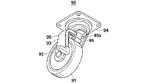
- FIG. 10 shows the state of the wheel unit 90 when the brake is released, and FIG. 11 shows that the brake is operated. The state of the wheel part 90 at the time is shown.
- the wheel portion 90 includes a wheel 91 made of, for example, rubber tires, a wheel holding portion 93 that rotatably holds the wheel 91 around the axle 92, and a wheel holding portion 93 that is turnable.
- a mounting seat 94, a crank-like brake lever 95 held by the wheel holding portion 93, and a leaf spring 96 are provided.
- the brake lever 95 is held by the wheel holding portion 93 so as to be rotatable around an axis on the base end side (right end side in FIGS. 10 and 11).
- the wheel part 90 provided with the brake means as described above is applied to the leg part 10, the wheel part 91 is moved to move the radiation image capturing apparatus 1 to a predetermined position, and then the wheel 91 is braked. Therefore, it is possible to prevent the radiographic image capturing apparatus 1 from moving carelessly.
- a turning caster there is provided a turning caster provided with a brake means for preventing the turning portion from turning around a turning axis (AX2 in the example of FIG. 6). If such a turning caster is applied, it is possible to prevent the radiographic imaging apparatus 1 from moving carelessly by turning the turning portion while allowing the wheel to rotate.
- a wheel portion having such a brake means it is possible to apply a wheel portion capable of braking both the rotation of the wheel and the turning of the turning portion. It is.
- a button or lever installed in the vicinity of the handle 80 may be operated.
- the moving speed of the wheel portion 13 may be detected, and when the detected moving speed exceeds a certain set speed, the wheel portion 13 may be automatically braked. Further, when the detected moving speed exceeds a certain set speed, an alert by an alarm sound or blinking of a lamp may be generated to alert the user of the apparatus. Such an alert may be generated only, or the brake may be applied together therewith.
- the wheel unit 13 may be braked automatically. And when applying the brake to the wheel part 13 automatically as mentioned above, in order to prevent the radiographic imaging device 1 from falling down, the wheel part 13 is gradually decelerated and then the brake is applied completely. It is desirable to do. Further, when the brake is automatically applied to the wheel portion 13, it is desirable to apply the brake to the four wheel portions 13 in the same manner.
- the wheel unit 13 may be automatically braked and locked. In that case, it is desirable that a certain operation immediately before driving the radiation source 70 is detected, and the wheel unit 13 is automatically braked when it is detected.
- the operation include a release operation of a camera that performs optical image shooting for confirming the radiation irradiation range.
- FIG. 7 is a side view showing the main body 30 in a partially broken view.
- the housing 32 constituting the main body 30 is formed in a substantially thin rectangular parallelepiped shape, and an opening (not shown) is formed on the front surface thereof, that is, the surface on which the handle 80 protrudes. The opening is closed by a lid 32a.
- the casing 32 constituting the main body 30 is fixed to the base 31 in an inclined state so that the upper end 32b is closer to the radiation source 70 than the lower end 32c.
- the arrow A shown in FIG. 7 corresponds to the arrow A in FIG. 1.
- the radiation source 70 is located on the front side of the arrow A with respect to the housing 32. become.
- the housing 32 may be configured separately from the base 31 and then fixed to the base 31, or may be formed integrally with the base 31 from the beginning.
- a DC power supply circuit 37 In the housing 32, in addition to the battery 36 for driving the radiation source 70, a DC power supply circuit 37, a drive control circuit 38, and an inverter (DC-AC conversion circuit) 39 are accommodated. These circuits 37 to 39 divided into blocks are known circuits relating to driving of the radiation source 70, and Japanese Patent Application Laid-Open No. 2000-127834 shows an example thereof.
- the battery 36 and the circuits 37 to 39 can be exchanged, maintained, inspected, and repaired through the opening with the lid 32a opened.
- the arm portion 50 protrudes in one horizontal direction (arrow A direction) with respect to the main body portion 30, but all of the circuits 37 to 39 divided into blocks are described above. They are arranged side by side in the direction crossing the arrow A direction. More specifically, as shown in a schematic arrangement state in FIG. 8, the circuits 37 to 39 are arranged side by side in an arrow B direction intersecting with the arrow A direction and in an arrow C direction also intersecting with the arrow A direction.
- the arrow B direction and the arrow C direction are respectively a vertical direction and a horizontal direction of the casing 32 which is formed into a substantially thin rectangular parallelepiped shape.
- the casing 32 that is, the main body is arranged.
- the portion 30 can be formed thinner.
- the battery 36 is also arranged side by side in the direction of the arrow B together with the circuits 37 to 39, which is more advantageous for forming the main body 30 thin.
- the casing 32 has a shape that is longer in the vertical direction than in the horizontal direction.
- the main body 30 can be formed thin by arranging the battery 36 and the circuits 37 to 39 side by side in the direction intersecting the arrow A direction.
- the battery 36 and the circuits 37 to 39 may be arranged side by side only in the direction of arrow B or in the direction of arrow C.
- a base portion 35 of a rod-like auxiliary leg 34 is attached to the side surface of the holding member 33 so as to be rotatable around a rotation axis AX6.
- the holding member 33 is provided with a slit 33a extending inward from the side surface. For example, an electronic cassette described later can be stored in the slit 33a.
- the leg portion 10 can be turned on the apparatus mounting surface 2 so that the four wheel portions 13 follow a common circle.
- the radiographic image capturing apparatus 1 can be turned using the legs 10 in order to change the traveling direction or to direct the radiation source 70 in a desired direction. It is. That is, the turning of the leg portion 10 in which the four wheel portions 13 follow different circles around a vertical line that is not inside the four wheel portions 13 in a plan view is a large turn. It turns. Note that the above-mentioned “smallest turn” is performed when the leg portion 10 turns so that at least two wheel portions 13 follow a common circle.
- FIG. 12 shows the main body 30 and the base 31 on the leg 10 in a plan view. As shown here, the main body 30 exists in a circular locus C2 drawn by the outermost end of the leg 10. Similarly, the base 31 is also present in the circular locus C2.
- the device user when turning the radiographic imaging device 1 in the smallest turn in order to change the direction of the radiation source 70, the device user will prevent the outermost end of the leg 12 from hitting anything. If care is taken, it is possible to avoid hitting the main body 30 or the base 31 with anything.
- the main body 30 has a length L1 in a direction (arrow A direction) in which the arm 50 protrudes from the main body 30 in a plan view, and a direction perpendicular to the direction (arrow B direction). ) Is shorter than the length L2.
- the radiographic imaging apparatus 1 is slim and does not occupy a large space when the arm part 50 is housed in the cylindrical member 51 with the shortest arm part 50 as will be described later. It can be of shape.
- the length L1 is preferably shorter than 1/3 of the length L2.
- the main body 30 can rotate relative to the leg 10 around the rotation axis AX1, but it is desirable to provide a locking means for preventing this rotation.
- a locking means in conjunction with a brake operation means (for example, the brake lever 95 in FIG. 10) for applying a brake to the wheel portion 13, when the brake is applied to the wheel portion 13, the main body portion 30 is simultaneously provided.
- the structure which locks rotation of this is preferable. Or the thing of the structure which locks rotation of the main-body part 30 by single operation may be sufficient. If such a locking means is provided, the radiation source 70 is rotated when the radiation source 70 can be rotated around the rotation axis AX9 (see FIG. 16) with respect to the arm unit 50 as described later. It is possible to prevent the main body 30 from rotating together.
- the arm portion 50 is provided with a slit 51a extending in a cylinder axis direction in a part of a substantially cylindrical member, and has a substantially “C” -shaped cross-sectional shape, and the cylindrical member.
- a main body side arm 52 (a main body side portion of the arm portion) that can be accommodated in the cylinder 51 so as to be movable in the cylinder axis direction, and a radiation source side arm that can be accommodated in the cylindrical member 51 so as to be movable in the cylinder axis direction (Radiation source side portion of the arm portion) 53.
- the cylindrical member 51 is fixed on the base 31 in a state inclined in substantially the same direction as the case 32 inclined as described above.
- the cylindrical member 51 may have a substantially “C” -shaped cross-sectional shape as described above, or may have a cylindrical or rectangular tube shape, or a cross-sectional shape in which two arcs face each other. It may be a half-divided shape or the like.
- the lower end portion of the radiation source side arm 53 is connected to the upper end portion of the main body side arm 52 via the turning holding mechanism 54 so as to be turnable around the turning axis AX4.
- the turning axis AX4 is an axis extending in the horizontal direction.
- the radiation source side arm 53 turns around the turning axis AX4 in a direction in which the angle formed with the main body side arm 52 changes.
- the turning holding mechanism 54 holds both the radiation source side arm 53 and the body side arm 52 so as to turn through a friction mechanism. Accordingly, the radiation source side arm 53 can be turned by applying a strong external force to some extent, and does not turn unless an external force is applied, and maintains a relative angle with respect to the main body side arm 52.
- the main body side arm 52 incorporates a cylinder (not shown) that constitutes a gas spring, and together with a piston rod 55 combined with the cylinder, constitutes a main body side portion of the arm portion.
- the gas spring basically includes the cylinder in which gas is sealed, a piston that defines the inside of the cylinder into an upper chamber and a lower chamber, a communication path that connects the upper chamber and the lower chamber, and An opening / closing valve for opening and closing the passage, an operating lever for operating the opening / closing valve, and a piston rod 55 having an upper end coupled to the piston are configured.
- the gas spring having the above configuration is widely applied as a height adjusting mechanism in a chair or the like in which the height of the seating surface can be changed.
- the length of the arm portion 50 can be changed.
- the main body side portion of the arm portion consisting of the main body side arm 52 and the piston rod 55
- the main body side arm 52 and the piston rod 55 can be extended and contracted.
- the operation lever when the operation lever is pulled to keep the on-off valve open, the upper chamber and the lower chamber communicate with each other so that gas can flow between the two chambers.
- the main body side arm 52 can be relatively moved. Therefore, if the main body side arm 52 is pushed downward in the cylindrical member 51 by applying a certain amount of force, the entire main body side arm 52 is accommodated in the cylindrical member 51 as shown in FIG. In this state, a part of the radiation source side arm 53 is also accommodated in the cylindrical member 51 in a state where the longitudinal direction is aligned with the main body side arm 52. In this way, when the main body side arm 52 and the radiation source side arm 53 are accommodated in the cylindrical member 51, the turning holding mechanism 54 moves in the slit 51 a of the cylindrical member 51.
- the arm unit 50 When the radiographic imaging device 1 is not used, the arm unit 50 is in the state shown in FIG. Under this state, a part of the radiation source side arm 53 is located in the cylindrical member 51, and therefore it is impossible for the radiation source side arm 53 to turn around the turning axis AX4. That is, in the present embodiment, the cylindrical member 51 serves as a turning restricting means for making the turning of the radiation source side arm 53 impossible when the main body side portion of the arm portion 50 is shorter than a predetermined length. .
- the “predetermined length” in this case is the length of the main body side portion of the arm portion 50 (main body) that slightly brings the lower end of the radiation source side arm 53 out of the cylindrical member 51.
- the on-off valve When the operation lever is released after the state of FIG. 4 is reached, the on-off valve is closed and the gas flow is restricted, so that the state is maintained. Thereafter, when the on-off valve is opened by operating the operation lever, the main body side arm 52 can move relative to the piston rod 55 as described above, and the repulsive force of the gas compressed in the upper chamber The main body side arm 52 moves up in the cylindrical member 51. At this time, the main body side arm 52 can rise to a position where the upper end protrudes from the cylindrical member 51 as shown in FIG. In this state, the entire source-side arm 53 also comes out of the cylindrical member 51, so that the source-side arm 53 can turn around the turning axis AX4.
- the on-off valve When the on-off valve is opened as described above and the main body side arm 52 is raised in the cylindrical member 51, if the operation lever is released and the on-off valve is closed, the gas flow is The main body side arm 52 is restricted and stops at the position at that time. In this way, the length by which the main body side arm 52 projects from the cylindrical member 51, that is, the total length of the arm portion 50 can be adjusted.
- the radiation source 70 is configured by housing, for example, an X-ray tube, a booster circuit, a cooling means for cooling the X-ray tube, and the like in a housing.
- the radiation source 70 is attached to the tip of the radiation source side arm 53 described above via a support member 71 so as to be swingable around the swing axis AX5.
- the rocking of the radiation source 70 is rocking in a direction in which the elevation angle of the radiation emitting axis RC changes as indicated by an arrow F in FIG. If the radiation source 70 can be swung in this way, it is possible to take a radiation image with respect to subjects at various positions by changing the direction of the radiation emission axis RC.
- the rocking position of the radiation source 70 that can be swung can be fixed by operating the lock lever 72.
- the radiation source 70 takes a rocking position in which the radiation output axis RC faces downward as compared with the case where the radiation source 70 is fixed by the action of its own weight. Yes.
- This downward swing position is most preferably the vertical swing position. If configured as described above, for example, after radiographic imaging of the subject is completed, the radiographic imaging device 1 is moved laterally away from the subject, and then the radiation is accidentally irradiated toward the subject. Can be prevented.
- radiographic imaging by the radiographic imaging apparatus 1 having the above configuration will be described.
- the radiographic image capturing apparatus 1 is carried to the use position while traveling on the apparatus mounting surface 2 such as a hospital floor by the wheel section 13 of the leg section 10 in the non-use state shown in FIG.
- the radiographic imaging device 1 can move in the front-rear and left-right directions, and can also move so as to make a large curve. It is also possible to swivel, so that it can be quickly brought to the use position with a small turn.
- the radiographic image is taken on a subject H lying on a supine table 3 such as a bed as shown in FIG.
- the radiographic imaging device 1 can be moved in the height direction of the subject H like a crab walking by the wheel unit 13 formed of a turning caster. It is. Thereby, the radiographic imaging device 1 can be easily set at the optimum position.
- the radiographic imaging apparatus 1 since the main body 30 is generally thin as described above, and the holding member 33 is also thin, the radiographic imaging apparatus 1 has a narrow space, for example, between the beds. You can easily get into. Since the main body 30 and the holding member 33 are generally thin, the radiographic imaging apparatus 1 is set at a position very close to the bed while inserting the leg 10 into the space under the bed. It becomes easy. If this is the case, the position adjustment of the radiation source 70 by expanding and contracting and turning the arm unit 50 can be reduced, and the time required for imaging can be shortened from that point.
- the main body side arm 52 of the arm unit 50 is extended to an arbitrary position protruding on the cylindrical member 51 as described above.
- the radiation source side arm 53 of the arm unit 50 is pivoted about the pivot axis AX4 to set the radiation source 70 at the optimum position, and the radiation source 70 is pivoted about the pivot axis AX5 to emit the radiation output axis.
- RC is set to the optimal orientation.
- the base 31 holding the arm part 50 is rotatable about the rotation axis AX1 on the leg part 10, the direction of the arm part 50 is changed by this rotation, It is also possible to adjust the position and orientation of the radiation source 70.
- the radiation source side arm 53 of the arm unit 50 cannot be turned until the main body side arm 52 extends to a position where the main body side arm 52 protrudes above the cylindrical member 51 by the action of the cylindrical member 51 as described above. Therefore, it is possible to prevent a problem that the radiation source side arm 53 is turned in a state where the radiation source 70 is at a relatively low position and the radiation source 70 hits the subject H. Further, since the arm portion 50 generally protrudes in a direction (arrow A direction) that is closer to the subject H than the main body portion 30, the radiation source 70 can be opposed to the subject H at a position far from the main body portion 30. It becomes possible to arrange.
- the rod-like auxiliary leg 34 is rotated around the rotation axis AX6, and the tip is brought into contact with the apparatus mounting surface 2 as shown in FIG.
- a non-slipable member such as rubber is attached to the tip of the auxiliary leg 34 to prevent slipping.
- the auxiliary leg 34 in this state becomes a so-called “stretching rod” to prevent the radiographic imaging apparatus 1 from falling over to the distal end side of the radiation source side arm 53 where the heavy radiation source 70 is held.
- an outrigger-like member for preventing the fall of a crane truck is accommodated in the holding member 33, and the member is pulled out in the direction of arrow A for use in radiographic imaging. Also good.
- radiographic images are taken by placing, for example, an electronic cassette 110 described later below the subject H, and irradiating the electronic cassette 110 through the subject H with radiation (for example, X-rays) R emitted from the radiation source 70.
- radiation for example, X-rays
- a command for driving the radiation source 70 is issued using the console 82.
- a conventionally known storage phosphor sheet IP: Imaging Plate
- a cassette in which an X-ray silver salt film is housed in a housing may be used.
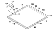
- the electronic cassette 110 will be briefly described with reference to FIGS. FIG. 14 and FIG. 15 respectively show the external appearance of the electronic cassette 110 viewed from the front side and the back side.
- the electronic cassette 110 of this example is used for, for example, medical X-ray imaging, and includes an image detection unit 115 that detects a transmitted X-ray image of the subject H based on the X-rays transmitted through the subject, and an image detection unit 115. And a portable casing 116 that accommodates the container.
- the image detection unit 115 includes a scintillator (phosphor) that converts incident X-rays into visible light, and a TFT (Thin Film Transistor) active matrix substrate.
- a scintillator phosphor
- TFT Thin Film Transistor
- the housing 116 is provided with a gate driver that applies a gate pulse to the gate of the TFT to switch the TFT, and converts the charge accumulated in the pixel into a voltage signal representing an X-ray image.
- a signal processing circuit for output, a gate driver, a control unit for controlling driving of the signal processing circuit, and the like are incorporated.
- the housing 116 has a rectangular parallelepiped shape including a front surface 120 on which X-rays are incident, a rear surface 121 facing the front surface 120, and four side surfaces 122, 123, 124, and 125.
- the housing 116 is formed of, for example, a conductive resin, and also functions as an electromagnetic shield that prevents electromagnetic noise from entering the electronic cassette 110 and radiating electromagnetic noise from the electronic cassette 110 to the outside.
- the casing 116 has a size conforming to an international standard ISO (International Organization for Standardization) 4090: 2001, which is substantially the same as, for example, a film cassette, an IP (Imaging Plate) cassette, or a CR (Computed Radiography) cassette.
- ISO International Organization for Standardization
- a rectangular opening is formed in the front surface 120, and a transmission plate 126 is attached to the opening.
- a resin protective film (not shown) that transmits X-rays is attached to the surface of the transmission plate 126.
- the transmission plate 126 is a plane size slightly larger than the imaging region, and is made of a carbon material that is lightweight, has high rigidity, and has high X-ray transparency.
- the electronic cassette 110 includes a control device that controls the operation of the electronic cassette 110, an antenna that generates radio waves for wirelessly communicating various information such as X-ray images, and an oscillation circuit.
- the electronic cassette 110 is driven by the electric power from the battery 128 and can be used without a so-called cable.
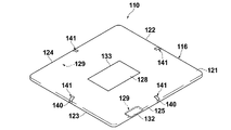
- the electronic cassette 110 includes a female connector 129 for wired communication with a control device (not shown).
- a male connector 130 is connected to the female connector 129.
- One end of a cable 131 for connecting the electronic cassette 110 and the control device to each other by wire is connected to the male connector 130.
- the other end of the cable 131 is connected to a connector (not shown) connected to the control device.
- the female connector 129 is covered and protected by a lid 132 when the male connector 130 is not connected, such as during use of the wireless communication function.
- the electronic cassette 110 receives not only various information but also power supply from the control device via the female connector 129.
- the electronic cassette 110 is driven by the electric power from the control device. It is also possible to charge the battery 128 with electric power from the control device.
- a battery mounting portion 133 is provided in the center portion of the back surface 121.
- a battery 128 that supplies electric power for driving the electronic cassette 110 is detachably attached to the battery attachment portion 133.
- FIG. 15 shows a state where the battery 128 is attached to the battery attachment portion 133.
- the battery mounting portion 133 is a concave portion in which the back surface 121 is recessed toward the front surface 120.
- the battery mounting portion 133 is formed in the same shape and the same size as the planar shape and the planar size of the battery 128 so that the battery 128 can be accommodated with almost no gap.
- the depth of the battery mounting portion 133 from the back surface 121 is also substantially the same as the thickness of the battery 128. Therefore, in the illustrated state where the battery 128 is mounted on the battery mounting portion 133, the upper surface of the battery 128 is exposed from the rear surface 121, and the upper surface of the battery 128 and the rear surface 121 are flush with each other.
- the electronic cassette 110 is provided with four marks 140 and four indicators 141 each composed of a light emitting element such as an LED or an organic EL (Electro-Luminescence) element. These marks 140 and indicators 141 serve to inform the operator of the center position of each side of the rectangular imaging region.
- a light emitting element such as an LED or an organic EL (Electro-Luminescence) element.
- the electronic cassette 110 After the X-ray image information is recorded on the electronic cassette 110, the electronic cassette 110 is connected to an image recording device or an image display device that receives a voltage signal representing the X-ray image, and based on this signal, the transmission of the subject H is transmitted. An X-ray image is recorded or reproduced and displayed.
- the main body side arm 52 and the radiation source side arm 53 of the arm unit 50 shown in FIG. 3 and the like are connected via a gas spring 97 as shown in FIG. It is desirable not to face downward from the state. By doing so, when the radiation source 70 (see FIG. 3) held at the distal end of the radiation source side arm 53 is placed above the subject H and the radiography is performed, the radiation source side arm 53 is inadvertent. It is possible to avoid a situation in which the radiation source 70 hits the subject H by turning downward.
- FIG. 13 the same elements as those in FIGS. 1 to 12 described above are denoted by the same reference numerals, and description thereof will be omitted unless necessary (hereinafter the same). .
- one end portion and the other end portion of the gas spring 97 are respectively connected to the holding portion 98 fixed to the main body side arm 52 and the holding portion 99 fixed to the radiation source side arm 53. It is rotatably held around the rotation axes AX7 and AX8.
- the holding portions 98 and 99 projecting from the arms 52 and 53, respectively. Is positioned in the slit 51 a of the tubular member 51. As a result, even if these protruding holding portions 98 and 99 are provided, the arms 52 and 53 can be accommodated in the cylindrical member 51.
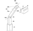
- the arm part 200 shown in FIG. 16 includes a cylindrical outer member 61 whose base end portion is connected to the main body part 30 (see FIG. 2 and the like), and a cylindrical shaft in the outer member 61. It is comprised from the inner member 62 which was accommodated so that the movement to the direction was possible, and connected the source side arm 63 to the front end side so that turning was possible.
- the radiation source side arm 63 is connected to the inner member 62 via a connecting portion 64 so as to be rotatable about a turning axis AX4.
- the cylindrical outer member 61 is formed in a rectangular tube shape as an example.
- the inner member 62 is accommodated with respect to the outer member 61 via an appropriate friction mechanism or a gas spring as described above. Therefore, the inner member 62 can be stopped at an arbitrary position in the cylinder axis direction with respect to the outer member 61 to maintain the state.
- a part of the radiation source side arm 63 enters the outer member 61 with the inner member 62 and the longitudinal direction aligned.
- the radiation source side arm 63 cannot turn around the turning axis AX4.
- the source-side arm 63 cannot be swiveled under a state where the main body side portion of the arm portion composed of the outer member 61 and the inner member 62 is shorter than a predetermined length.
- the length of the outer member 61 is set to the above-mentioned “predetermined length”, and the outer member 61 constitutes the turning restricting means.
- the length of the main body side portion of the arm portion compared with the “predetermined length” is the length from the proximal end of the outer member 61 to the distal end of the inner member 62.
- this rule is the same when the tip of the inner member 62 is located in the outer member 61.
- the outer member 61 constituting the main body side portion of the arm portion is disposed so that the longitudinal direction is perpendicular to the device mounting surface 2 (see FIG. 2 and the like).
- the radiation source side arm 63 is comprised from the comparatively long elongate part 63a and the comparatively short front-end
- the distal end portion 63b is connected to the elongated portion 63a so as to be rotatable around a rotation axis AX9 parallel to the longitudinal direction of the radiation source side arm 63.
- the radiation source 70 is connected to the distal end portion 63b so as to be swingable around the swing axis AX5 in a state where the distal end portion 63b is sandwiched between the two support members 77.
- the radiation source 70 attached to the radiation source side arm 63 as described above can further rotate around the rotation axis AX9 together with the distal end portion 63b in addition to the above-described swinging, various radiation irradiation directions can be set. This is advantageous.
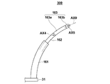
- the arm portion may have a curved shape.
- FIG. 17 is a side view showing an example of the arm portion having such a curved shape.
- the arm part 300 in FIG. 17 is the same as the outer member 61, the inner member 62, the long part 63a, and the tip part 63b in the arm part 200 in FIG. And has a long portion 163a and a tip portion 163b.
- the long arm 163a and the tip 163b constitute a radiation source side arm 163.
- the structure for attaching the radiation source 70 to the tip 163b is the same as that in the arm 200 of FIG.
- the distal end portion 163b can be rotated around a rotation axis AX9 parallel to the longitudinal direction of the radiation source side arm 163, as in the arm portion 200 of FIG.
- the “longitudinal direction of the radiation source side arm 163” in this case is more precisely the tangential direction of the end of the curved arm portion on the radiation source mounting side.
- the “longitudinal direction” is defined as not including the object in the arm portion.
- a height adjustment mechanism capable of adjusting the height from the wheel portion to the radiation source support portion is further provided.
- a height adjustment mechanism capable of adjusting the height from the wheel portion to the radiation source support portion.
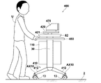
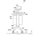
- a radiographic image capturing apparatus 400 shown in FIG. 18 includes a leg portion 410, a main body 30 held on the leg portion 410, a handle 480 for pushing and pulling the radiographic image capturing apparatus 400, a console 82, and the like. , A radiation source 470, a support base 420 that supports the radiation source 470, and an elevating mechanism 421 that is fixed to the upper end and can be moved up and down with respect to the main body 30.
- the main body 30 holds the electronic cassette 110 so as to be removable.
- the main body 30 and the console 82 are basically the same as those shown in FIG.
- the electronic cassette 110 is the same as that described above, but in this embodiment, the electronic cassette 110 is held in the main body 30 in a different orientation from that in the radiographic imaging apparatus 1 of FIG. It has become.
- the support table 420 is a radiation source support unit in the present embodiment, and the radiation source 470 is mounted on the support table 420 so as to emit radiation in the lateral direction.
- the leg part 410 is composed of four legs 412 (only two are shown in the figure) and a wheel part 13 attached to the lower end of each leg 412.
- the wheel portion 13 is basically the same as that shown in FIG. 1, but here is attached to the leg 412 so as to be swingable around the swing axis AX10.
- the four legs 412 are interlocked with each other so that the angle with respect to the horizontal direction can be adjusted.
- the swinging positions of the legs 412 can be fixed by a fixing lever or the like (not shown) in a state where the angle is arbitrarily adjusted.
- the radiographic image capturing apparatus 400 of the present embodiment having the above-described configuration is capable of running and moving on the apparatus mounting surface 2 when the apparatus user U holds and pushes the handle 480 and pulls it. Thus, when the radiographic image capturing apparatus 400 is moved, the elevating mechanism 421 is lowered to, for example, the lowest position.
- the radiation image capturing apparatus 400 is used in an emergency medical institution or the like, for example, to capture a chest standing image of a subject H sitting on an imaging table 450 as shown in FIG. That is, in this case, the radiation R emitted from the radiation source 470 in the lateral direction passes through the subject, and a transmitted radiation image of the subject H by the radiation R is captured and recorded in the electronic cassette 110.
- the elevating mechanism 421 is moved up by an appropriate distance, and the radiation source 470 is set to an optimum position with respect to the height position of the subject H.
- the angles of the four legs 412 are changed in a direction in which the lower ends approach each other as shown in FIG. Thereby, the height from the wheel part 13 to the support stand 420 becomes longer, and the radiation source 470 is set to a higher position.
- the radiographic image capturing apparatus 400 of the present embodiment is used when the apparatus user U moves by pushing or pulling the radiographic image capturing apparatus 400. It is also possible to change the height from the wheel portion 13 to the handle 480 by changing the angle of the four legs 412 in order to facilitate the operation according to the height of the wheel.
- the two legs 412 that can change the angle with respect to the horizontal direction and the two mechanisms of the elevating mechanism 421. Is applied, but only one of them may be applied.
- a radiation source 470 is mounted on the support base 420 so as to emit radiation R downward after applying a mechanism having a relatively long lifting stroke as the lifting mechanism 421, a chest image or abdominal part of a subject in a lying position is provided. It is also possible to take an image. In that case, it is also possible to set the distance SID (Source) Image Distance) between the radiation source and the radiation detector to a desired value by operating the height adjusting mechanism.
- SID Source
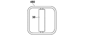
- FIG. 21 shows a planar shape of the handle 480.
- the handle 480 has a shape that surrounds the entire circumference of the main body 30. If the handle 480 has such a shape, the radiographic image capturing apparatus 400 can be pushed and pulled from any of the front, rear, left, and right sides of the main body 30. , Mobility becomes higher.
- FIG. 22 shows a state where the electronic cassette 110 is not held in the main body 30.
- a radiographic imaging apparatus 500 shown in FIG. 23 includes a leg lower part 510, a leg upper part 511 fixed on the leg lower part 510, a main body part 530 held on the leg upper part 511, a console 82, A main body side arm 552 attached to the main body portion 530 via a hinge, a radiation source side arm 553 attached to the main body side arm 552 via a hinge, and attached to the radiation source side arm 553 via a hinge.
- a radiation source 570 is attached to the main body portion 530 via a hinge, a radiation source side arm 553 attached to the main body side arm 552 via a hinge, and attached to the radiation source side arm 553 via a hinge.
- the main body 530 is of a horizontal type. Further, the main body side arm 552 and the radiation source side arm 553 constitute a radiation source support section in the present embodiment.
- the leg lower part 510 and the leg upper part 511 together with the wheel part 13 attached to the lower end of the leg lower part 510 constitute a leg part in this embodiment.
- the leg lower portion 510 includes a connecting portion 510a extending in the lateral direction, four lower outer cylinders 510b connected obliquely to the connecting portion 510a, and lower inner cylinders 510c inserted through the respective lower outer cylinders 510b. It is configured.
- the leg upper part 511 is comprised from the upper outer cylinder 511a and the upper inner cylinder 511b by which this upper outer cylinder 511a was penetrated.
- the lower end of the upper inner cylinder 511b is fixed to the connecting portion 510a.
- the wheel portion 13 is attached to the lower end of the lower inner cylinder 510c.
- the main body 530 is fixed to the upper end of the upper outer cylinder 511a.
- the insertion length of the upper inner cylinder 511b with respect to the upper outer cylinder 511a can be adjusted, and the both cylinders 511a and 511b constitute a telescopic cylinder mechanism. That is, when the insertion length is adjusted, the entire length of the upper outer cylinder 511a and the upper inner cylinder 511b expands and contracts. Further, the insertion length of the lower inner cylinder 510c with respect to the lower outer cylinder 510b can also be adjusted, and the both cylinders 510b and 510c constitute an extendable cylinder mechanism. That is, when the insertion length is adjusted, the entire length of the lower outer cylinder 510b and the lower inner cylinder 510c expands and contracts.
- both the cylinders 511a and 511b constituting the leg upper part 511 are connected through, for example, a gas spring as described above. Therefore, the upper inner cylinder 511b can be stopped at an arbitrary position in the cylinder axis direction with respect to the upper outer cylinder 511a, and the state can be maintained.
- the lower inner cylinder 510c in the leg lower part 510 can maintain the cylinder axial position with respect to the lower outer cylinder 510b, for example, by tightening a set screw.
- the main body side arm 552 and the radiation source side arm 553 are extended as shown in FIG. 24 and FIG.
- the source 570 is set to emit radiation downward or laterally.
- the above-described SID is adjusted.
- the height position of the radiation source 570 is adjusted to the height of the subject. Therefore, as shown in FIG. 25, the entire length of the upper outer cylinder 511a and the upper inner cylinder 511b can be appropriately extended. Thereby, the radiation source 570 can be set at a higher position.
- the entire length of the lower outer cylinder 510b and the lower inner cylinder 510c can be appropriately extended to set the radiation source 570 at a higher position.
- a radiographic image capturing apparatus 600 shown in FIG. 26 is fixed on four wheel parts 13 (only three are shown in the figure), a base part 631 constituting a leg part together with the wheel parts 13, and the base part 631.
- a main body 630 an arm support 632 attached to the main body 630 via an elevating mechanism described later, a radiation source 670, a radiation source holding member 671 that holds the radiation source 670, and the radiation source holding member
- the first arm 672 is swingable in the direction of arrow K with respect to the second arm 674 by the action of the first joint 673.
- the second arm 674 is swingable in the direction of arrow L with respect to the arm support portion 632 by the action of the second joint 675.
- the height position of the radiation source 670 can be changed by swinging the first arm 672 and the second arm 674 as described above.
- the second joint 675 is attached to the arm support 632 so as to be rotatable in the direction of arrow S in the horizontal plane.
- the arm support 632 is connected to a lifting mechanism (not shown) disposed in the main body 630.
- the elevating mechanism 640 is, for example, a pantograph type, and includes an upper end member 641 to which the arm support portion 632 is connected, a lower end member 642 fixed to, for example, the base 631 in the main body portion 630, and an upper end member 641. It is composed of a plurality of pantograph arms 643 that connect the lower end member 642.
- the elevating mechanism 640 by extending and contracting the pantograph arm 643, the vertical position of the upper end member 641, that is, the height position of the arm support portion 632 connected thereto can be changed.
- the height position of the arm support portion 632 When the height position of the arm support portion 632 is changed as described above, the heights of the first arm 672 and the second arm 674 in FIG. 26 are changed, and consequently the height position of the radiation source 670 is changed.
- the height position of the radiation source 670 is changed as described above to thereby change the radiation source.
- the distance SID Source Image Distance
- the height position of the arm support portion 632 can be maintained at an arbitrary position, for example, by tightening a set screw for suppressing the vertical movement of the upper end member 641.
- the second joint 675 is attached to the arm support 632 so as to be rotatable in the direction of the arrow S in FIG. 26, so that the first arm 672 and the second arm The position of the radiation source 670 can be changed by swinging 674 in this direction.
- FIG. 28 shows a state in which the omni wheel 700 is attached to the leg 12 of the radiographic imaging apparatus 1 shown in FIG. 1 as an example.
- the omni wheel 700 is one of omnidirectional wheels, and is attached to the axle 701 and can rotate forward and backward around the rotation axis AX11, and a plurality of attached to the outer periphery of the rotation body 702. And a roller 703.
- a roller 703 for example, a barrel-type roller is applied.
- seven rollers 703, that is, a total of 14 rollers 703 are attached to the left and right.
- Each of the seven rollers 703 on the left and right sides is attached to the rotating body 702 so as to be able to rotate forward and backward about a rotation axis AX12 extending in the tangential direction of one circle coaxial with the rotation axis AX11.
- the seven rollers 703 on one side of the left and right are respectively disposed at positions facing the gaps between the seven rollers 703 on the other side of the left and right.
- the omni wheel 700 having the above configuration is attached to the leg 12 via a bearing portion 704 that receives the axle 701.
- the rotating body 702 and the 14 rollers 703 constitute one rotating wheel. That is, when a force acting in the direction of the arrow P in the figure is applied to the radiographic imaging device having the legs 12, the wheel composed of the rotating body 702 and the roller 703 has the 14 rollers 703 as the outer peripheral surface of the wheel and the rotation axis AX11. To facilitate the movement of the leg 12, that is, in the direction of the arrow P of the radiographic apparatus. When a force acting in the direction of arrow Q in the figure is applied to the radiographic imaging apparatus having the legs 12, the grounded roller 703 rotates around the rotation axis AX12, and the leg 12, that is, the radiographic image. The movement of the photographing apparatus in the arrow Q direction is facilitated.
- a Mecanum wheel disclosed in Japanese Patent Laid-Open No. 2013-081659 is also applicable.
Landscapes
- Health & Medical Sciences (AREA)
- Life Sciences & Earth Sciences (AREA)
- Engineering & Computer Science (AREA)
- Medical Informatics (AREA)
- Physics & Mathematics (AREA)
- Biomedical Technology (AREA)
- Molecular Biology (AREA)
- General Health & Medical Sciences (AREA)
- Nuclear Medicine, Radiotherapy & Molecular Imaging (AREA)
- Optics & Photonics (AREA)
- High Energy & Nuclear Physics (AREA)
- Animal Behavior & Ethology (AREA)
- Public Health (AREA)
- Heart & Thoracic Surgery (AREA)
- Radiology & Medical Imaging (AREA)
- Surgery (AREA)
- Pathology (AREA)
- Biophysics (AREA)
- Veterinary Medicine (AREA)
- Mechanical Engineering (AREA)
- Computer Networks & Wireless Communication (AREA)
- General Physics & Mathematics (AREA)
- Spectroscopy & Molecular Physics (AREA)
- Automation & Control Theory (AREA)
- Robotics (AREA)
- Apparatus For Radiation Diagnosis (AREA)
Abstract
【課題】放射線源支持部に放射線源を保持させてなる放射線画像撮影装置を、小回りが利く状態で迅速に使用位置まで運ばれ得るように構成する。 【解決手段】3個以上の車輪部(13)を有して、装置載置面上を車輪(14)で走行可能とされた脚部(10)と、脚部(10)の上に保持された本体部(30)と、本体部(30)に連結された放射線源支持部としてのアーム部(50)と、アーム部(50)に取り付けられた放射線源(70)と、本体部(30)内に収容されて放射線源(70)を駆動するバッテリと、本体部(30)内に収容されて放射線源(70)の駆動に関わる回路とを備えた放射線画像撮影装置において、車輪部(13)を旋回キャスタから構成する。
Description
本発明は放射線画像撮影装置、より詳しくは、アーム部等に放射線源を支持させてなる放射線画像撮影装置に関するものである。
従来、例えば特許文献1や非特許文献1に示されているように、放射線源と電気回路等の放射線照射のための最小限の構成要素のみを搭載し、操作者が手で持って操作可能とした可搬型(ポータブル)の放射線照射装置が提案されている。この種の可搬型の放射線照射装置は、操作者が手で持って操作できる程度に軽量化されており、被写体を様々な方向から撮影する上で有利なものとなっている。
上述のような可搬型の放射線照射装置を用いて被写体の放射線画像を撮影する際には、通常、蓄積性蛍光体シート(IP:Imaging Plate)やX線用銀塩フイルムが筐体内に収納されてなるカセッテが用いられる。すなわち、そのようなカセッテを、被写体を間に置いて放射線照射装置に対向する位置に配し、その状態で放射線照射装置を駆動させれば、被写体を透過したX線等の放射線がカセッテ内の蓄積性蛍光体シート等に照射され、該蓄積性蛍光体シート等に被写体の透過放射線画像が記録される。なお近時は、上述のようなカセッテに代えて、後述するいわゆる電子カセッテが用いられることも多い。特許文献2には、この電子カセッテの一例が示されている。
上記の可搬型の放射線照射装置は、操作者が手で持って操作可能なものであるが、手振れを防止し、さらには操作者の手等への被ばくを防止するために、支持装置に支持した状態で使用するのが望ましい。非特許文献1には、そのような支持装置の例も示されており、特に、脚の下部に車輪部を設けて走行可能とした支持装置も示されている。
上記の走行可能とした支持装置と可搬型の放射線照射装置とを組み合わせてなる放射線画像撮影装置は、被写体を様々な方向から容易に撮影可能であって、また機動性も備えているので、例えば救急室等での使用に好適なものとなっている。
他方、例えば特許文献3や特許文献4に示されるように、アーム部に放射線源を取り付けて使用するようにした放射線画像撮影装置も公知となっている。この種の放射線画像撮影装置は多くの場合、基本的に、脚部と、放射線源駆動用のバッテリや放射線源の駆動に関わる電気回路を収容して脚部の上に保持された本体部と、本体部に連結されたアーム部と、アーム部に取り付けられた放射線源とを備えたものとされている。
上記の基本構成を有する放射線画像撮影装置は、狭い所にも容易に運ぶことができる、交流電源が利用できない環境下でも使用可能であるといった有利性を活かして、病院等の医療機関において救急搬送された患者や、狭い病室のベッドに寝ている患者の放射線画像を撮影する等のために特に好適に利用されている。
東芝医療用品株式会社、X線撮影装置 IPF-21、[online]、[平成11年7月30日検索]、インターネット〈URL:http://www.toshiba-iryouyouhin.co.jp/tmeds/xrays/ipf21.html〉
しかしながら、非特許文献1に示されている放射線画像撮影装置、つまり走行可能とした支持装置と可搬型の放射線照射装置とを組み合わせてなる放射線画像撮影装置や、さらには特許文献3や特許文献4に示されている放射線画像撮影装置は、いずれも小回りが利くものではなく、よって、狭い所を通して迅速に使用位置まで運ぶ上で改良の余地が残されている。
本発明は上記の事情に鑑みてなされたものであり、小回りが利いて、迅速に使用位置まで運ぶことができる放射線画像撮影装置を提供することを目的とする。
本発明による第1の放射線画像撮影装置は、
3個以上の車輪部を有して、装置載置面上を車輪で走行可能とされた脚部と、
脚部の上に保持された本体部と、
本体部に連結されたアーム部等からなる放射線源支持部と、
放射線源支持部に取り付けられた放射線源と、
本体部内に収容されて放射線源を駆動するバッテリと、
本体部内に収容されて放射線源の駆動に関わる回路とを備えた放射線画像撮影装置において、
車輪部が旋回キャスタから構成されていることを特徴とするものである。
3個以上の車輪部を有して、装置載置面上を車輪で走行可能とされた脚部と、
脚部の上に保持された本体部と、
本体部に連結されたアーム部等からなる放射線源支持部と、
放射線源支持部に取り付けられた放射線源と、
本体部内に収容されて放射線源を駆動するバッテリと、
本体部内に収容されて放射線源の駆動に関わる回路とを備えた放射線画像撮影装置において、
車輪部が旋回キャスタから構成されていることを特徴とするものである。
また本発明は、上記旋回キャスタの代わりに全方向移動車輪を適用した第2の放射線画像撮影装置を提供するものである。すなわち、本発明による第2の放射線画像撮影装置は、
3個以上の車輪部を有して、装置載置面上を車輪で走行可能とされた脚部と、
脚部の上に保持された本体部と、
本体部に連結された放射線源支持部と、
放射線源支持部に取り付けられた放射線源と、
本体部内に収容されて放射線源を駆動するバッテリと、
本体部内に収容されて放射線源の駆動に関わる回路とを備えた放射線画像撮影装置において、
車輪部が全方向移動車輪から構成されていることを特徴とするものである。
3個以上の車輪部を有して、装置載置面上を車輪で走行可能とされた脚部と、
脚部の上に保持された本体部と、
本体部に連結された放射線源支持部と、
放射線源支持部に取り付けられた放射線源と、
本体部内に収容されて放射線源を駆動するバッテリと、
本体部内に収容されて放射線源の駆動に関わる回路とを備えた放射線画像撮影装置において、
車輪部が全方向移動車輪から構成されていることを特徴とするものである。
なお、上記の全方向移動車輪は、例えば特開2010-076630号公報や特開2012-030735号公報等に示されているオムニホイール(登録商標)やメカナムホイールのように、走行時に水平な向きになる回転軸を中心として回転する回転体と、この回転体と同軸の1つの円に沿うようにして回転体に取り付けられた複数のローラとからなるものであり、上記回転体が回転することによって第1の方向に移動し、また上記ローラが回転することにより、上記第1の方向と交わる第2の方向に移動可能とされたものである。ここで、上記の「水平」とは、通常水平な装置載置面上に脚部が載っている状態下で、装置載置面と平行であることをいう。また、上記ローラの回転軸は、上記回転体と同軸の1つの円の接線方向、あるいはそれに近い方向に延びるように設定される。
なお、上記構成を有する本発明の放射線画像撮影装置においては、特に望ましい形態として、
本体部が脚部に対して、上下方向に延びる回転軸を中心として相対回転可能とされ、
アーム部等からなる放射線源支持部が、本体部から水平な一方向に突出しており、
本体部が、平面視状態で、上記一方向と平行な方向の長さが、上記一方向と直角な方向の長さよりも短くなる形状とされる。
本体部が脚部に対して、上下方向に延びる回転軸を中心として相対回転可能とされ、
アーム部等からなる放射線源支持部が、本体部から水平な一方向に突出しており、
本体部が、平面視状態で、上記一方向と平行な方向の長さが、上記一方向と直角な方向の長さよりも短くなる形状とされる。
ここで上記の「水平」とは、上に述べたのと同様に、通常水平な装置載置面上に脚部が載っている状態下で、装置載置面と平行であることをいう。また、水平方向に突出しているとは、水平方向成分を持って斜めに突出していることも含むものである。また、上記の「平面視状態」とは、装置載置面に投影した場合の状態を意味するものである。
また、上記の「長さ」は最大長さを指すものであり、そして本体部の辺が各方向に対して傾いている場合も、同じく上記一方向の最大長さを指すものとする。
また、本発明の放射線画像撮影装置が上述の特に望ましい形態とされる場合、本体部は、平面視状態で、上記一方向と平行な方向に関する長さが、上記一方向と直角な方向に関する長さの1/3以下となる形状であることが好ましい。
また、本発明の放射線画像撮影装置が上述の特に望ましい形態とされる場合、本体部は、上端が下端と比べてより放射線源に近付く状態に傾斜していることが好ましい。
また、本発明の放射線画像撮影装置が上述の特に望ましい形態とされる場合、本体部は、バッテリおよび放射線源の駆動に関わる回路を、概略直方体状の筐体内に収容して構成されることが好ましい。
また、本発明の放射線画像撮影装置が上述の特に望ましい形態とされる場合、放射線源の駆動に関わる回路は複数のブロックに分けて構成され、それら複数のブロックが全て上記一方向と交わる方向に並べて配置されていることが好ましい。
また、本発明の放射線画像撮影装置においては、脚部が装置載置面上で、少なくとも2個の車輪部が共通の1つの円上を辿るように旋回した際に脚部の最外端が描く円形軌跡と、本体部とを平面視状態で重ね合わせたとき、本体部が全て上記の円形軌跡内に位置していることが好ましい。
ここで、上記脚部の「最外端」とは、円形軌跡の径方向に関する最外端、つまり、円形軌跡の中心から最も径方向遠方に位置する端部である。またこの「最外端」は車輪部の最外端とは限らず、車輪部を下面に取り付けていて車輪部よりも外に広がっている四角形の基台等が有る場合は、その基台等の最外端であってもよい。
また、本発明の放射線画像撮影装置においては、放射線源支持部が伸縮自在とされていることが好ましい。
さらに、本発明の放射線画像撮影装置においては、放射線源が、放射線源支持部の中の放射線源が取り付けられている部分の長手方向と平行な軸の周りに回転可能とされていることが好ましい。
また、本発明の放射線画像撮影装置においては、放射線源が、放射線出射軸の仰角が変わる方向に揺動可能とされた上で、放射線源の揺動位置を固定する揺動位置固定手段が設けられていることが好ましい。そして上記の構成とする場合は特に、放射線源が、揺動位置固定手段による揺動位置の固定が解除されたとき、自重の作用により、固定がなされている場合よりも放射線出射軸が下向きになる揺動位置を取るように構成されていることが望ましい。
また、本発明の放射線画像撮影装置においては、車輪部がブレーキ手段を備えていることが望ましい。
また、本発明の放射線画像撮影装置においては、車輪部から放射線源支持部までの高さを調節できる高さ調節機構がさらに設けられることが望ましい。
上述のような高さ調節機構は、具体的には、水平方向に対する角度を調節自在とした上記脚部から構成されるのが好ましい。
あるいは、上記高さ調節機構は、上記車輪部と放射線源支持部との間の少なくとも一部に設けられた伸縮筒機構から構成されてもよい。
さらに、上記高さ調節機構は、本体部において放射線源支持部に連結する部分を昇降させる昇降機構から構成されてもよい。
本発明の放射線画像撮影装置は、車輪部が旋回キャスタあるいは全方向移動車輪から構成されたことにより、前後左右方向に移動可能で、また大きくカーブするようにも移動可能であり、さらにはその場で旋回すること(つまり人間に例えれば、体軸の周りに回転するようなこと)も可能であり、よって小回りが利く状態で迅速に使用位置まで運ばれ得るものとなる。
以下、図面を参照して本発明による放射線画像撮影装置の実施形態について説明する。図1は本発明の一実施形態による放射線画像撮影装置1の全体形状を示す斜視図であり、また図2および図3はそれぞれ放射線画像撮影装置1の非使用時、使用時の状態を示す側面図、そして図4および図5はそれぞれ放射線画像撮影装置1の非使用時、使用時の状態を示す後面図である。
なお以下では、例えば医療機関の床等の装置載置面2上に放射線画像撮影装置1が載置された状態において、鉛直方向上側、下側をそれぞれ「上」、「下」と称し、また、同じ状態において鉛直方向に対して直角となる方向を「水平」方向ということとする。
図1~図5に示されるように本実施形態の放射線画像撮影装置1は、装置載置面2上を走行可能とされた脚部10と、この脚部10の上に保持された本体部30と、この本体部30に連結された放射線源支持部としてのアーム部50と、このアーム部50の先端部に取り付けられた放射線源70とを有している。なお、本体部30とアーム部50との連結は、直接的になされてもよいし、あるいは間に何らかの部材を介して間接的になされてもよい。
上記本体部30は、概略厚い板状の基部31の上に固定された筐体32内に、後述するバッテリ等の要素を収容して構成されている。筐体32の上端には、放射線画像撮影装置1を押したり引いたりするための把手80が取り付けられている。また上記基部31の上には保持部材33が固定されており、この保持部材33の上部には、受け台81を介してコンソール82が保持されている。
コンソール82は、放射線画像撮影装置1の各種動作を指示する信号等を入力するための操作ボタンやスイッチ等の入力手段83や、放射線画像撮影装置1の状態や、入力手段83による入力情報等を表示するための表示手段84等を備えている。なお、表示手段84をいわゆるタッチパネルから構成して、該タッチパネルへの接触操作により信号入力等を行うようにして、入力手段83を省くことも可能である。
脚部10は、水平な台座11と、この台座11の偶部から各々側外方に延びた一例として4本の脚12と、各脚12の先端部下面の車輪取付け部12aに取り付けられた車輪部13とを有している。前述した基部31は、上記台座11の上に、上下方向に延びる回転軸AX1を中心として回転可能に保持されている。それにより、基部31に固定された本体部30や後述するアーム部50は、脚部10に対して回転軸AX1を中心として、つまり水平面内で相対回転可能となっている。
図6は、車輪部13の近辺の側面形状を示すものである。同図に示される通り車輪部13は、上下方向に延びる旋回軸AX2の周りに旋回自在とされた、いわゆる旋回キャスタからなるものである。すなわち車輪部13は、例えばゴムタイヤ等からなる車輪14と、この車輪14を水平な車軸AX3を中心として回転可能に保持する車輪保持部15と、この車輪保持部15と一体化された旋回部16とを備えており、旋回部16が旋回軸AX2の周りに旋回可能にして脚12の車輪取付け部12aに取り付けられている。
上記旋回軸AX2は、水平面内で車軸AX3からオフセットした位置に設定されている。したがって、脚部10を水平な一方向に動かせば、その一方向内において前側に旋回軸AX2が位置し、後側に車輪14が位置するように旋回部16が旋回して、車輪14が自由に回転できるようになる。そこで、放射線撮影技師等の作業者が前述の把手80を握って放射線画像撮影装置1を押したり引いたりすれば、放射線画像撮影装置1を任意の方向に簡単かつ迅速に移動させることができる。
また、本実施形態において4個の車輪部13は、平面視状態、つまり装置載置面2に投影して見た状態で、各旋回軸AX2が、共通の1つの長方形の角に位置する状態に配置されている。そこで、概略その長方形の重心位置を通る鉛直線を中心として脚部10の全体を水平面内、つまり装置載置面2上で回転させることも可能である。そのように脚部10が回転する際、4個の車輪部13は、共通の1つの円の上を辿るように円弧を描きながら走行する。
車輪部13を構成する上述の旋回キャスタとしては、従来公知の例えばキャスタ付き事務用椅子、物品運搬用キャスタ付きワゴン、あるいはキャスタ付き作業台等において広く用いられているものを適宜選択して適用することができる。
なお、以上述べたような車輪部13に代えて、ブレーキ手段を備えた車輪部を用いてもよい。図10および図11は、ブレーキ手段を備えた車輪部90の一例を示す斜視図であり、図10はブレーキが解放されているときの車輪部90の状態を、また図11はブレーキが作動したときの車輪部90の状態を示している。
図示のようにこの車輪部90は、例えばゴムタイヤ等からなる車輪91と、この車輪91を車軸92の周りに回転可能に保持する車輪保持部93と、この車輪保持部93を旋回可能に保持した取り付け座94と、車輪保持部93に保持されたクランク状のブレーキレバー95と、板ばね96とを備えている。ブレーキレバー95は、基端側(図10、11中で右端側)の軸周りに回転可能にして車輪保持部93に保持されている。
ブレーキレバー95が図10の回転位置にあるとき、板ばね96は車輪91から離れていて、車輪91は回転可能となっている。この状態からブレーキレバー95が回転されて図11の回転位置に動かされると、該ブレーキレバー95の基端側の軸に形成されている凸部95aが板ばね96を押して、車輪91の周面に圧接させる。それにより車輪91は回転不可能になって、ブレーキが掛けられた状態となる。
以上の通りのブレーキ手段を備えた車輪部90を脚部10に適用すれば、脚部10を走行させて放射線画像撮影装置1を所定の位置に移動させた後、車輪91にブレーキを掛けることにより、放射線画像撮影装置1が不用意に動いてしまうことを防止可能となる。
また、旋回キャスタとしては、旋回部が旋回軸(図6の例ならばAX2)の周りに旋回しないようにするブレーキ手段を備えたものも提供されている。そのような旋回キャスタを適用すれば、車輪の回転は許容しながらも、旋回部が旋回して放射線画像撮影装置1が不用意に動いてしまうことを防止可能となる。本発明においては、その種のブレーキ手段を備えた車輪部を適用することも可能であり、さらには、車輪の回転と旋回部の旋回の双方にブレーキを掛け得る車輪部を適用することも可能である。
また、車輪部13にブレーキを掛けるためには、上述のブレーキレバー95を操作する他に、例えば把手80の近辺に設置したボタンやレバーを操作するようにしてもよい。また、車輪部13の移動速度を検出し、検出された移動速度がある設定速度を超えた場合は、車輪部13に自動的にブレーキを掛けるようにしてもよい。また、検出された移動速度がある設定速度を超えたら、警報音やランプ点滅等によるアラートを発生させて、装置使用者に注意を促すようにしてもよい。そのようなアラートは発生させるだけでもよいし、それと共に上記ブレーキが掛かるようにしてもよい。
さらには、装置使用者が把手80から手を離したことが検知されると、車輪部13に自動的にブレーキを掛けるようにしてもよい。そして、以上のように車輪部13に自動的にブレーキを掛ける場合は、放射線画像撮影装置1の転倒を防止するために、車輪部13を徐々に減速させてから完全にブレーキが掛かるように構成することが望ましい。また、車輪部13に自動的にブレーキを掛ける場合は、4個の車輪部13に同じようにブレーキを掛けることが望ましい。
また、放射線画像の撮影時に放射線画像撮影装置1が、つまりは放射線源70が動いてしまうことを防止するために、車輪部13に自動的にブレーキを掛けてロックするようにしてもよい。その場合は、放射線源70を駆動する直前の何らかの操作を検知して、それが検知されたら車輪部13に自動的にブレーキが掛かるように構成するのが望ましい。なお、上記の操作としては、例えば放射線照射範囲を確認するための光学像撮影を行うカメラのレリーズ操作等が挙げられる。
次に、本体部30について、図7および図8も参照して詳しく説明する。図7は、本体部30を一部破断して示す側面図である。同図および図1に明示されるように、本体部30を構成する筐体32は概略薄い直方体状に形成され、その前面、つまり把手80が突出している側の面には、図示外の開口が設けられ、その開口は蓋32aによって閉じられている。
本実施形態において、本体部30を構成する筐体32は、上端32bが下端32cと比べてより放射線源70に近付くように傾斜した状態で基部31に固定されている。なお図7に示した矢印Aは、図1中の矢印Aと対応するものであり、図7中では筐体32に対して、この矢印Aの前方側に放射線源70が位置していることになる。筐体32は、基部31とは別体に構成した後に基部31に固定されてもよいし、あるいは、最初から基部31と一体的に形成されても構わない。
筐体32内には、放射線源70を駆動するためのバッテリ36に加えて、DC電源回路37、駆動制御回路38およびインバータ(直流-交流変換回路)39が収容されている。ブロックに分けられたこれらの回路37~39は、放射線源70の駆動に関わる公知の回路であり、特開2000-127834号公報にはそれらの一例が示されている。バッテリ36および回路37~39に対しては、蓋32aを開いた状態で上記開口を通して交換、保守・点検、修理等を行うことができる。
図2および図3に明示される通り、アーム部50は本体部30に対して、水平な一方向(矢印A方向)に突出しているが、ブロックに分けられた回路37~39は全て、上記矢印A方向と交わる方向に並べて配置されている。より詳しくは、図8に概略配置状態を示す通り、回路37~39は矢印A方向と交わる矢印B方向、および同じく矢印A方向と交わる矢印C方向に並べて配置されている。矢印B方向および矢印C方向は各々、概略薄い直方体状とされた筐体32の縦方向および横方向であり、これらの方向に回路37~39を並べて配置することにより、筐体32つまりは本体部30をより薄く形成することが可能になる。また本実施形態では特にバッテリ36も、回路37~39と共に矢印B方向に並べて配置されているので、本体部30を薄く形成する上でより有利となっている。
本実施形態では、筐体32が横方向よりも縦方向が長い形状とされているが、図9に概略形状を示すように筐体32を、横方向よりも縦方向が短い形状とすることも可能である。そうする場合でも、バッテリ36および回路37~39を、矢印A方向と交わる方向に並べて配置することにより、本体部30を薄く形成可能となる。なお、筐体32が著しく縦長あるいは著しく横長に形成されるような場合は、バッテリ36および回路37~39を矢印B方向のみ、あるいは矢印C方向のみに並べて配置してもよい。
保持部材33の側面には、図2および図3に明示されるように、回動軸AX6の周りに回動可能として、棒状の補助脚34の基部35が取り付けられている。また保持部材33には、図3に明示されるように、側面から内方に延びるスリット33aが設けられている。このスリット33aには、例えば後述する電子カセッテ等を収納しておくことができる。
ここで、脚部10と本体部30の大きさの関係について、図12を参照して説明する。前述した通り脚部10は、装置載置面2の上で、4個の車輪部13が共通の1つの円の上を辿るように旋回可能である。放射線画像撮影装置1は、走行方向を変えたり、放射線源70を所望の方向に向けたりするために脚部10を使って旋回可能であるが、上述のような旋回が最も「小回り」な旋回である。すなわち、平面視状態で4個の車輪部13の内側には無い鉛直線を中心として、4個の車輪部13が互いに異なる円の上を辿るようになされる脚部10の旋回は、大回りな旋回となる。なお、上述の最も「小回り」な旋回がなされるのは、少なくとも2個の車輪部13が共通の1つの円の上を辿るように脚部10が旋回する場合である。
図12には、脚部10が上記最も小回りな旋回をするときに4個の車輪部13が辿る共通の円をC1として示し、また、その際に脚12の最外端(つまり脚部10の最外端)が描く円形軌跡をC2として示してある。またこの図12には、脚部10の上に有る本体部30および基部31を平面視した状態で示してある。ここに図示される通り本体部30は、脚部10の最外端が描く円形軌跡C2の中に存在している。また、同様に基部31も円形軌跡C2の中に存在している。
以上のようになっていれば、放射線源70の向きを変えるために放射線画像撮影装置1を最も小回りに旋回させる際、脚12の最外端が何かに当たることが無いように装置使用者が注意してさえいれば、本体部30や基部31が何かに当たることを回避できる。
また図12に示す通り本体部30は、平面視した状態で、アーム部50が本体部30から突出している方向(矢印A方向)の長さL1が、該方向と直角な方向(矢印B方向)の長さL2よりも短くなる形状となっている。本体部30をこのような形状とすることにより、放射線画像撮影装置1を、後述するようにアーム部50を最も短くして筒状部材51内に収容した際に広い場所を占有しない、スリムな形状のものとすることができる。なお、上記の長さL1は一般に、長さL2の1/3よりも短いことが望ましい。
本体部30は先に説明した通り、脚部10に対して回転軸AX1を中心として相対回転可能となっているが、この回転を阻止するロック手段を設けておくことが望ましい。そのようなロック手段としては、車輪部13にブレーキを掛けるためのブレーキ操作手段(例えば図10のブレーキレバー95等)と連動して、車輪部13にブレーキが掛けられた際に同時に本体部30の回転をロックする構成のものが好ましい。あるいは、単独の操作によって本体部30の回転をロックする構成のものでもよい。そのようなロック手段を設けておけば、後述するように放射線源70がアーム部50に対して回転軸AX9(図16参照)の周りに回転可能とされた場合に、放射線源70を回転させると一緒に本体部30も回転してしまうことを防止可能となる。
次に図1~図5に戻って、アーム部50について詳しく説明する。アーム部50は、概略円筒形の部材の一部に筒軸方向に延びるスリット51aが設けられて、概略「C」型の断面形状を有するものとされた筒状部材51と、この筒状部材51内に筒軸方向に移動可能にして収容され得る本体側アーム52(アーム部の本体側部分)と、同じく筒状部材51内に筒軸方向に移動可能にして収容され得る線源側アーム(アーム部の放射線源側部分)53とを有している。筒状部材51は、前述のように傾斜した筐体32とほぼ同じ向きに傾斜した状態にして、基部31の上に固定されている。なお筒状部材51は、上述のように概略「C」型の断面形状を有するものとする他、円筒状や角筒状のものとされてもよいし、2つの円弧が向き合った断面形状を有する、2つ割りの形状等とされても構わない。
線源側アーム53の下端部は本体側アーム52の上端部に対して、旋回保持機構54を介して、旋回軸AX4の周りに旋回可能に連結されている。旋回軸AX4は水平方向に延びる軸である。線源側アーム53はこの旋回軸AX4を中心にして、本体側アーム52となす角度が変わる向きに旋回する。なお旋回保持機構54は、線源側アーム53が本体側アーム52に対して摩擦機構を介して旋回するように両者を保持している。そこで線源側アーム53は、ある程度強い外力が加えられることによって旋回可能で、外力が加えられない限り旋回せず、本体側アーム52に対する相対角度を維持する。
本体側アーム52は、ガススプリングを構成する図示外のシリンダを内蔵しており、そのシリンダと組み合わされたピストンロッド55と共に、アーム部の本体側部分を構成している。上記ガススプリングは基本的に、ガスが封入された上記シリンダと、該シリンダ内を上室と下室に画成するピストンと、これらの上室と下室とを連通させる連通路と、この連通路を開閉する開閉弁と、この開閉弁を操作する操作レバーと、上記ピストンに上端が連結されたピストンロッド55とを備えて構成されている。
上記構成のガススプリングは、従来、座面の高さを変更可能とした椅子等において高さ調節機構として広く適用されているものであり、本実施形態ではアーム部50の長さを変更できるように、アーム部の本体側部分(本体側アーム52およびピストンロッド55からなる)を伸縮可能としている。以下、その点について詳しく説明する。
上記操作レバーを例えば引き操作して開閉弁を開状態に保つと、上記上室と下室とが連通してガスが両室間で流通可能になり、ピストンロッド55に対してシリンダが、つまりは本体側アーム52が相対移動可能となる。そこで、ある程度の力を加えて本体側アーム52を筒状部材51内で下方に押し込めば、図4に示すように、本体側アーム52全体が筒状部材51内に収容される。この状態になると、線源側アーム53の一部も、本体側アーム52と長手方向が揃った状態で筒状部材51内に収容される。なお、こうして本体側アーム52および線源側アーム53を筒状部材51内に収容させるとき、旋回保持機構54は、筒状部材51のスリット51a内を移動する。
放射線画像撮影装置1が使用されない場合、アーム部50は図4に示した状態とされる。この状態下では、線源側アーム53の一部が筒状部材51内に位置しているので、該線源側アーム53が旋回軸AX4の周りに旋回することは不可能となる。つまり本実施形態においては筒状部材51が、アーム部50の本体側部分が予め定められた長さより短い状態下では、線源側アーム53の旋回を不可能にする旋回規制手段となっている。なお、この場合の上記「予め定められた長さ」は、線源側アーム53の下端を僅かに筒状部材51の外に出すようになる、アーム部50の本体側部分の長さ(本体側アーム52と、そこから突出しているピストンロッド55の部分との合計長さ)である。
図4の状態になった後、上記操作レバーが解放されれば、開閉弁が閉状態になってガスの流通が規制されるので、その状態が保たれる。その後、操作レバーを操作して開閉弁が開状態にされると、上述した通りピストンロッド55に対して本体側アーム52が相対移動可能となり、そして上室内で圧縮されているガスの反発力により、本体側アーム52が筒状部材51内を上昇する。このとき本体側アーム52は、図3に示すように、上端が筒状部材51から飛び出た位置まで上昇し得る。この状態になると、線源側アーム53も全体が筒状部材51から抜け出るので、該線源側アーム53は旋回軸AX4の周りに旋回可能となる。
なお、開閉弁が上述のように開状態にされて本体側アーム52が筒状部材51内を上昇しているとき、上記操作レバーが解放されて開閉弁が閉状態になると、ガスの流通が規制されて本体側アーム52はその時の位置で停止する。こうして、本体側アーム52が筒状部材51から突出する長さ、つまりはアーム部50の全長を調整することができる。
他方、放射線源70は、筐体内に例えばX線管球、昇圧回路、X線管球を冷却する冷却手段等を収めて構成されている。そして放射線源70は、上に説明した線源側アーム53の先端部に、支持部材71を介して揺動軸AX5の周りに揺動自在に取り付けられている。この放射線源70の揺動は、図3に矢印Fで示すように、放射線出射軸RCの仰角が変わる方向の揺動である。このように放射線源70が揺動可能となっていれば、放射線出射軸RCの向きを変えて、種々の位置にある被写体に対して放射線画像の撮影が可能となる。
揺動可能とされた放射線源70は、ロックレバー72を操作することにより、揺動位置が固定され得るようになっている。そして放射線源70は、ロックレバー72による揺動位置の固定が解除されたとき、自重の作用により、固定されている場合よりも放射線出射軸RCが下向きになる揺動位置を取るようになっている。この下向きになる揺動位置は、最も好ましくは、鉛直方向下向きとなる揺動位置である。以上のように構成されていれば、例えば被写体に対する放射線画像の撮影が終了して、放射線画像撮影装置1を被写体から離れるように横方向に移動させた後に、誤って被写体に向けて放射線が照射されることを防止可能となる。
次に、上記構成の放射線画像撮影装置1による放射線画像の撮影について説明する。放射線画像撮影装置1は図2に示す非使用時の状態のまま、脚部10の車輪部13にて病院の床等の装置載置面2上を走行させながら使用位置まで運ばれる。このとき、車輪部13が前述した通りの旋回キャスタから構成されているので、放射線画像撮影装置1は前後左右方向に移動可能で、また大きくカーブするようにも移動可能であり、さらにはその場で旋回することも可能であり、よって小回りが利く状態で迅速に使用位置まで運ばれ得る。
放射線画像の撮影は、一例として図3に示すように、ベッド等の仰臥台3の上に仰臥している被写体Hに対して行われる。図3に示す撮影位置に放射線画像撮影装置1をセットするに当たっては、旋回キャスタからなる車輪部13により放射線画像撮影装置1を、被写体Hの身長方向にいわばカニ歩きのように移動させることも可能である。それにより、放射線画像撮影装置1を容易に最適位置にセットすることができる。
その際、本体部30が前述したように全体的に薄い形状とされ、また保持部材33も薄い形状とされているので、放射線画像撮影装置1は例えばベッドとベッドとの間のような狭いスペースにも容易に進入して行くことができる。また、本体部30および保持部材33が全体的に薄い形状とされているので、脚部10をベッドの下の空間に差し込みつつ、放射線画像撮影装置1をベッドに非常に近づいた位置にセットすることも容易となる。そうであれば、アーム部50の伸縮や旋回による放射線源70の位置調整は、より少なくて済むようになり、その点から撮影所要時間を短縮可能となる。
放射線画像撮影装置1が最適位置にセットされた後、アーム部50の本体側アーム52が、前述したようにして筒状部材51の上に突出した任意位置まで伸ばされる。次いで、アーム部50の線源側アーム53を旋回軸AX4の周りに旋回させて放射線源70が最適位置に設定され、そして放射線源70を揺動軸AX5の周りに揺動させて放射線出射軸RCが最適な向きに設定される。
さらに本実施形態では、アーム部50を保持している基部31が、脚部10の上で回転軸AX1を中心として回転可能となっているので、この回転によってアーム部50の向きを変えて、放射線源70の位置や向きを調整することも可能である。
なお、アーム部50の線源側アーム53は、前述した通り筒状部材51の作用により、本体側アーム52が筒状部材51の上に突出する位置まで伸びてからでないと旋回不可能であるので、放射線源70が比較的低い位置にある状態で線源側アーム53が旋回されて、放射線源70が被写体Hに当たるような問題を防止できる。またアーム部50は、全体的に本体部30よりも、被写体Hにより接近できる方向(矢印A方向)に突出しているので、放射線源70を、本体部30から遠い位置にある被写体Hに対向できるように配置可能となる。
またこのとき、棒状の補助脚34が回動軸AX6の周りに回動されて、図3に示すように先端が装置載置面2に接する状態とされる。なお補助脚34の先端には、スリップ防止用に、例えばゴム等の滑り難い部材が取り付けられている。この状態になった補助脚34は、いわゆる「突っ張り棒」となって、放射線画像撮影装置1が、重い放射線源70が保持されている線源側アーム53の先端側に転倒することを防止する。なお、上記のような補助脚34の代わりに、例えばクレーン車の転倒防止用アウトリガー状の部材を保持部材33に収容し、放射線画像撮影時にはその部材を矢印A方向に引き出して使用するようにしてもよい。
本例において放射線画像の撮影は、被写体Hの下に例えば後述する電子カセッテ110を配置し、放射線源70から出射した放射線(例えばX線)Rを、被写体Hを通して該電子カセッテ110に照射することによってなされる。なお、放射線源70の駆動の指令等は、コンソール82を用いてなされる。また、電子カセッテ110に代えて、従来公知の蓄積性蛍光体シート(IP:Imaging Plate)やX線用銀塩フイルムが筐体内に収納されてなるカセッテが用いられてもよい。
ここで図14および図15を参照して、電子カセッテ110について簡単に説明する。図14および図15はそれぞれ、電子カセッテ110を前面側、背面側から見た外観を示している。本例の電子カセッテ110は、例えば医療用X線撮影に利用されるもので、被写体を透過したX線に基づいて被写体Hの透過X線画像を検出する画像検出部115と、画像検出部115を収容する可搬型の筐体116とを備えている。
画像検出部115は、周知のように、入射したX線を可視光に変換するシンチレータ(蛍光体)、およびTFT(Thin Film Transistor)アクティブマトリクス基板を備える。TFTアクティブマトリクス基板上には、シンチレータからの可視光に応じた電荷を蓄積する複数の画素が配列された矩形状の撮像領域が形成される。筐体116には、この画像検出部115の他に、TFTのゲートにゲートパルスを与えてTFTをスイッチングさせるゲートドライバ、画素に蓄積された電荷を、X線画像を表す電圧信号に変換して出力する信号処理回路、ゲートドライバや信号処理回路の駆動を制御する制御部等が内蔵されている。
筐体116は、X線が入射する前面120、前面120と対向する背面121、および4つの側面122、123、124、125で構成される直方体形状を有する。筐体116は例えば導電性樹脂で形成され、電子カセッテ110内への電磁ノイズの侵入、および電子カセッテ110内から外部への電磁ノイズの放射を防止する電磁シールドとしても機能する。筐体116は、例えば、フイルムカセッテやIP(Imaging Plate)カセッテ、CR(Computed Radiography)カセッテと略同様の、国際規格ISO(International Organization for Standardization)4090:2001に準拠した大きさである。
前面120には矩形状の開口が形成されており、開口には透過板126が取り付けられている。透過板126の表面には、X線を透過させる樹脂製の保護フイルム(図示せず)が貼り付けられている。これにより前面120は平坦面となる。透過板126は、上記撮像領域よりも若干大きい平面サイズであり、軽量で剛性が高く、かつX線透過性が高いカーボン材料から形成されている。
電子カセッテ110は、電子カセッテ110の動作を制御する制御装置や、X線画像等の各種情報を無線通信するための電波を発生するアンテナや発振回路を備えている。この無線通信機能を使用した場合には、電子カセッテ110はバッテリ128からの電力で駆動し、いわゆるケーブルレスで使用することが可能である。
また、電子カセッテ110は、図示外の制御装置と有線通信するためのメス型コネクタ129を備えている。メス型コネクタ129には、オス型コネクタ130が接続される。オス型コネクタ130には、電子カセッテ110と上記制御装置とを有線接続するためのケーブル131の一端が接続される。ケーブル131の他端は、上記制御装置に接続するコネクタ(図示せず)に接続されている。メス型コネクタ129は、無線通信機能の使用中等、オス型コネクタ130が接続されないときには蓋132で覆われて保護される。
電子カセッテ110は、メス型コネクタ129を介して、上記制御装置から各種情報だけでなく電力の供給も受ける。電子カセッテ110は、メス型コネクタ129とオス型コネクタ130が接続された場合、上記制御装置からの電力で駆動する。また、上記制御装置からの電力でバッテリ128を充電することも可能である。
背面121の中央部分には、バッテリ装着部133が設けられている。バッテリ装着部133には、電子カセッテ110を駆動するための電力を供給するバッテリ128が着脱自在に装着される。図15ではバッテリ128がバッテリ装着部133に装着された状態を示している。
バッテリ装着部133は、背面121を前面120に向けて凹ませた凹部である。バッテリ装着部133は、バッテリ128が略隙間なく収まるように、バッテリ128の平面形状および平面サイズと同一形状および同一サイズに形成されている。バッテリ装着部133の背面121からの深さも、バッテリ128の厚みと略同じである。このため、バッテリ128がバッテリ装着部133に装着された図示の状態では、バッテリ128の上面が背面121から露呈し、バッテリ128の上面と背面121とが同一平面となる。
電子カセッテ110には、マーク140と、例えばLEDや有機EL(Electro-Luminescence)素子等の発光素子から構成されたインジケータ141とが4つずつ設けられている。これらのマーク140およびインジケータ141は、矩形状の撮像領域の各辺の中心位置をオペレータに報せる役割を果たすものである。
電子カセッテ110にX線画像情報が記録された後、該電子カセッテ110は、X線画像を表す電圧信号を受ける画像記録装置や画像表示装置と接続され、この信号に基づいて、被写体Hの透過X線画像が記録あるいは再生表示される。
ここで、図3等に示したアーム部50の本体側アーム52と線源側アーム53とは、図13に示すようにガススプリング97を介して連結して、線源側アーム53が水平な状態よりも下向きにならないようにしておくことが望ましい。そうすることにより、線源側アーム53の先端部に保持された放射線源70(図3参照)を被写体Hの上方に配置して撮影するような場合に、線源側アーム53が不用意に下向きになって、放射線源70が被写体Hに当たるような事態を避けることができる。
なお、図13において、先に説明した図1~図12中のものと同等の要素には同番号を付してあり、それらについての説明は、特に必要の無い限り省略する(以下、同様)。図13の構成において、より詳しくは、本体側アーム52に固定された保持部98と、線源側アーム53に固定された保持部99とにそれぞれ、ガススプリング97の一端部、他端部が回動軸AX7、AX8の周りに回動可能に保持されている。なお、上記の本体側アーム52および線源側アーム53を、図3や図4等に示す筒状部材51の中に収容させるに当たっては、各アーム52、53から突出している保持部98、99を、筒状部材51のスリット51a内に位置させる。それにより、これらの突出した保持部98、99が設けられていても、アーム52、53を筒状部材51の中に収容可能となる。
次に図16を参照して、アーム部の別の例について説明する。図16に示すアーム部200は、アーム部の本体側部分が、基端が例えば本体部30(図2等参照)に連結される筒状の外部材61と、該外部材61内に筒軸方向に移動可能に収められて先端側に線源側アーム63を旋回可能に連結した内部材62とから構成されたものである。なお内部材62に対して線源側アーム63は、連結部64を介して、旋回軸AX4を中心に旋回可能に連結されている。また筒状の外部材61は、一例として角筒状に形成されている。
外部材61に対して内部材62は、適宜の摩擦機構を介して、あるいは前述したようなガススプリングを介して収容されている。そこで内部材62は外部材61に対して、任意の筒軸方向位置で停止して、その状態を維持することが可能となっている。そして、外部材61の深い位置まで内部材62を収容させれば、線源側アーム63も内部材62と長手方向が揃った状態で、一部が外部材61内に入り込むようになる。こうして線源側アーム63の一部が外部材61内に収容されていると、線源側アーム63は旋回軸AX4を中心に旋回することは不可能となる。
以上によりこのアーム部200においても、外部材61と内部材62とからなるアーム部の本体側部分が予め定められた長さより短い状態下では、線源側アーム63の旋回が不可能となっている。つまり本構成においては、外部材61の長さが上記の「予め定められた長さ」とされて、外部材61が旋回規制手段を構成している。なおこの場合、上記の「予め定められた長さ」と比較されるアーム部の本体側部分の長さは、外部材61の基端から内部材62の先端までの長さとする。この規定は便宜的上、内部材62の先端が外部材61の中に位置する場合も同様とする。
図16の構成において、アーム部の本体側部分を構成する外部材61は、長手方向が装置載置面2(図2等参照)に対して直角な向きになるように配設されている。また、線源側アーム63は、比較的長い長尺部63aと、この長尺部63aの先端に連結された比較的短い先端部63bとから構成されている。先端部63bは、線源側アーム63の長手方向と平行な回転軸AX9の周りに回転可能にして、長尺部63aに連結されている。そして放射線源70は、2つの支持部材77で上記先端部63bを挟む状態として、揺動軸AX5の周りに揺動自在にして先端部63bに連結されている。
以上のようにして線源側アーム63に取り付けられた放射線源70は、上記揺動の他にさらに、先端部63bと共に回転軸AX9の周りに回転可能となるので、放射線照射方向を種々に設定する上で有利なものとなる。
本発明の放射線画像撮影装置において、アーム部は湾曲した形状とされてもよい。図17は、そのように湾曲した形状のアーム部の一例を示す側面図である。この図17のアーム部300は、湾曲した以外は図16のアーム部200における外部材61、内部材62、長尺部63a、先端部63bと各々同様に形成された外部材161、内部材162、長尺部163a、先端部163bを有している。そして長尺部163aと先端部163bとによって、線源側アーム163が構成されている。また、図示は省略しているが、先端部163bに対する放射線源70の取り付け構造も、図16のアーム部200におけるものと同様である。
そして、先端部163bが、線源側アーム163の長手方向と平行な回転軸AX9の周りに回転可能とされているのも、図16のアーム部200におけるのと同じである。なおこの場合の「線源側アーム163の長手方向」は、より正確には、湾曲しているアーム部分の放射線源取り付け側の端部の接線方向となる。また、アーム部分に「長手」の無い物体、例えば球形のジョイント等を介して放射線源が取り付けられている場合、その物体はアーム部分に含まないこととして上記「長手方向」を規定する。
本発明の放射線画像撮影装置においては、車輪部から放射線源支持部までの高さを調節できる高さ調節機構がさらに設けられることが望ましい。以下、そのような高さ調節機構が設けられた放射線画像撮影装置の実施形態について説明する。
図18に示す放射線画像撮影装置400は、脚部410と、脚部410の上に保持された本体部30と、放射線画像撮影装置400を押したり引いたりするための把手480と、コンソール82と、放射線源470と、この放射線源470を支持した支持台420と、この支持台420を上端に固定して、本体部30に対して昇降可能とされた昇降機構421とを有している。なお本体部30には、取外し自在にして電子カセッテ110が保持される。
なお本体部30およびコンソール82は、図1に示したものと基本的に同様のものである。また、電子カセッテ110も既述のものと同様のものであるが、本実施形態では図1の放射線画像撮影装置1におけるのとは、向きが異なる状態にして本体部30に保持されるようになっている。支持台420は本実施形態における放射線源支持部であり、この支持台420の上において放射線源470は、横方向に放射線を発するように取り付けられている。
一方、脚部410は、4本の脚412(図中では2本のみ示す)と、各脚412の下端に取り付けられた車輪部13とから構成されている。車輪部13は図1に示したものと基本的に同様のものであるが、ここでは、脚412に対して揺動軸AX10の周りに揺動自在に取り付けられている。4本の脚412は互いに連動して、水平方向に対する角度を調節自在とされている。そしてそれらの脚412は、上記角度が任意に調節された状態で、図示外の固定レバー等によって揺動位置が固定され得るものとなっている。
以上の構成を有する本実施形態の放射線画像撮影装置400は、装置使用者Uが把手480を持って押したり引いたりすることにより、装置載置面2上を走行、移動可能となっている。こうして放射線画像撮影装置400が移動される際、昇降機構421は、例えば最も低い位置まで降りた状態にされている。
放射線画像撮影装置400は救急医療機関等において、例えば図19に示すように、撮影台450の上に座った状態にある被写体Hの胸部立位画像を撮影するために利用される。すなわちこの場合、放射線源470から横方向に発せられた放射線Rが被写体を透過し、この放射線Rによる被写体Hの透過放射線画像が電子カセッテ110に撮影、記録される。放射線画像の撮影に際しては、昇降機構421が適宜な距離だけ上昇動され、被写体Hの高さ位置に対して放射線源470が最適な位置に設定される。
なお、放射線源470をさらに高い位置に設定したい要求が有る場合は、図20に示すように4本の脚412の角度が、各下端が互いに近づく方向に変えられる。それにより、車輪部13から支持台420までの高さがより長くなって、放射線源470がさらに高い位置に設定される。本実施形態の放射線画像撮影装置400は、放射線源470の高さ位置を変えるための他、装置使用者Uが放射線画像撮影装置400を押したり引いたりして移動する際に、装置使用者Uの身長に合わせてその作業をし易くするために、4本の脚412の角度を変えて、車輪部13から把手480までの高さを変更することも可能である。
以上の通り本実施形態では、車輪部13から支持台420までの高さを変える高さ調節機構として、水平方向に対する角度を変更可能とした4本の脚412と、昇降機構421の2つの機構が適用されているが、それらのうちの片方だけが適用されてもよい。また、昇降機構421として、昇降ストロークが比較的長いものを適用した上で、放射線源470を支持台420において下向きに放射線Rを発するように取り付ければ、臥位状態にある被写体の胸部画像や腹部画像を撮影することも可能である。その場合は、上記高さ調節機構を操作して、放射線源と放射線検出器との間の距離SID(Source Image Distance)を所望の値に設定することも可能である。
ここで図21に、把手480の平面形状を示す。同図に示される通り、本実施形態において把手480は、本体部30の周りを全周に亘って取り囲む形状とされている。把手480がこのような形状とされていれば、放射線画像撮影装置400を本体部30の前後左右どの側からも押したり、引いたりすることが可能になるので、放射線画像撮影装置400の操作性、機動性がより高いものとなる。
なお、上述したように4本の脚412を、水平方向に対する角度を変更可能に構成する場合は、それらの脚412を互いに干渉しないように横方向にずらして設け、図22に示すように全部の脚412が揃う状態に上記角度を変更可能としておいてもよい。そうした場合は、同図に示されるように、放射線画像撮影装置400を全体的に斜めに倒して引っ張って、走行、移動させることが容易になる。なお図22は、本体部30に電子カセッテ110は保持されていない状態を示している。
次に、車輪部から放射線源支持部までの高さを調節できる高さ調節機構を有する放射線画像撮影装置の別の実施形態について説明する。図23に示す放射線画像撮影装置500は、脚下部510と、この脚下部510の上に固定された脚上部511と、この脚上部511の上に保持された本体部530と、コンソール82と、本体部530にヒンジを介して取り付けられた本体側アーム552と、この本体側アーム552にヒンジを介して取り付けられた線源側アーム553と、この線源側アーム553にヒンジを介して取り付けられた放射線源570とを有している。
本実施形態において本体部530は横置き型のものとされている。また本体側アーム552および線源側アーム553は、本実施形態における放射線源支持部を構成している。脚下部510および脚上部511は、脚下部510の下端に取り付けられた車輪部13と共に、本実施形態における脚部を構成している。
脚下部510は、横方向に延びる連結部510aと、この連結部510aに対して斜めに連結した4本の下部外筒510bと、各下部外筒510bにそれぞれ挿通された下部内筒510cとから構成されている。一方脚上部511は、上部外筒511aと、この上部外筒511a挿通された上部内筒511bとから構成されている。上部内筒511bの下端は、上記連結部510aに固定されている。また車輪部13は、下部内筒510cの下端に取り付けられている。そして本体部530は、上部外筒511aの上端に固定されている。
上部外筒511aに対する上部内筒511bの挿通長さは調節可能とされており、これら両筒511aおよび511bによって伸縮筒機構が構成されている。つまり上記挿通長さが調節されると、上部外筒511aと上部内筒511bの全体の長さが伸縮する。また、下部外筒510bに対する下部内筒510cの挿通長さも調節可能とされて、これら両筒510bおよび510cによって伸縮筒機構が構成されている。つまり上記挿通長さが調節されると、下部外筒510bと下部内筒510cの全体の長さが伸縮する。
なお、脚上部511を構成する上記両筒511aおよび511bは、例えば前述したようなガススプリングを介して連結されている。そこで上部内筒511bは上部外筒511aに対して任意の筒軸方向位置で停止して、その状態を維持することが可能となっている。他方、脚下部510における下部内筒510cは、例えば止めネジを締め付ける等により、下部外筒510bに対する筒軸方向位置を維持可能となっている。
以上の構成を有する本実施形態の放射線画像撮影装置500を使用する際には、図24および図25に時間を追って示すように本体側アーム552および線源側アーム553が延ばされ、そして放射線源570が例えば下方やあるいは横方向に放射線を発する向きに設定される。その際、例えば下方に放射線を発して撮影する場合は前述したSIDを調節するために、また例えば横方向に放射線を発して撮影する場合は放射線源570の高さ位置を被写体の高さに合わせるために、図25に示すように、上部外筒511aと上部内筒511bの全体の長さを適宜伸ばすことができる。それにより、放射線源570をより高い位置に設定可能となる。さらには、同じく図25に示すように、下部外筒510bと下部内筒510cの全体の長さを適宜伸ばして、放射線源570をより一層高い位置に設定することも可能である。
次に、車輪部から放射線源支持部までの高さを調節できる高さ調節機構を有する放射線画像撮影装置のさらに別の実施形態について説明する。図26に示す放射線画像撮影装置600は、4つの車輪部13(同図では3つのみ図示)と、この車輪部13と共に脚部を構成する基部631と、この基部631の上に固定された本体部630と、この本体部630に後述する昇降機構を介して取り付けられたアーム支持台632と、放射線源670と、この放射線源670を保持した線源保持部材671と、この線源保持部材671を支持した第1アーム672と、この第1アーム672の基端に第1関節673を介して先端が連結された第2アーム674と、この第2アーム674の基端に連結された第2関節675と、第2アーム674を支持したアーム支持部632とを有している。
第1アーム672は第1関節673の作用により、第2アーム674に対して矢印K方向に揺動自在とされている。第2アーム674は第2関節675の作用により、アーム支持部632に対して矢印L方向に揺動自在とされている。第1アーム672や第2アーム674を上記のように揺動させることにより、放射線源670の高さ位置を変えることができる。
また第2関節675は、アーム支持部632に対して、水平面内の矢印S方向に回動自在にして取り付けられている。そしてアーム支持部632は、本体部630内に配置された図示外の昇降機構に連結されている。
この昇降機構について、以下、図27を参照して説明する。昇降機構640は一例としてパンタグラフ型のものであり、上記アーム支持部632が連結された上端部材641と、本体部630内で例えば前述の基部631に固定された下端部材642と、上端部材641と下端部材642とを連結する複数のパンタグラフアーム643とから構成されたものである。この昇降機構640においては、パンタグラフアーム643を伸縮させることにより、上端部材641の上下位置、つまりはそこに連結されているアーム支持部632の高さ位置を変えることができる。
上述の通りにしてアーム支持部632の高さ位置が変えられると、図26において第1アーム672および第2アーム674の高さが変えられ、ひいては、放射線源670の高さ位置が変えられる。例えば放射線源670から下向きに放射線を発するようにして臥位状態にある被写体の胸部画像や腹部画像を撮影する際に、放射線源670の高さ位置を上述のようにして変えることにより、放射線源と放射線検出器との間の距離SID(Source Image Distance)を所望の値に設定することが可能になる。なおアーム支持部632の高さ位置は、例えば上記上端部材641の上下方向移動を抑制する止めネジを締め付ける等によって、任意の位置に維持させることができる。
また本実施形態においては、前述したように第2関節675がアーム支持部632に対して、図26の矢印S方向に回動自在にして取り付けられているので、第1アーム672および第2アーム674をこの方向に首振りさせて、放射線源670の位置を変えることもできる。
次に図28を参照して、本発明の放射線画像撮影装置において適用され得る車輪部の別の例について説明する。図28に示す車輪部は、例えばオムニホイール(登録商標)から構成されたものである。図28は一例として、このオムニホイール700が図1に示した放射線画像撮影装置1の脚12に取り付けられた状態を示している。
オムニホイール700は全方向移動車輪の一つであって、車軸701に取り付けられて回転軸AX11の周りを正逆回転可能である回転体702と、この回転体702の外周部に取り付けられた複数のローラ703とを有している。ローラ703としては、例えば樽型のローラが適用されている。
本例では回転体702において、左右に分けて7個ずつ、つまり合計で14個のローラ703が取り付けられている。左右一方側の7個のローラ703はそれぞれ、回転軸AX11と同軸の1つの円の接線方向に延びる回転軸AX12を中心に正逆回転可能にして、回転体702に取り付けられている。この点は、左右他方側の7個のローラ703についても同様である。また、左右一方側の7個のローラ703はそれぞれ、左右他方側の7個のローラ703同士の隙間に向かい合う位置に配されている。以上の構成を有するオムニホイール700は、車軸701を受承する軸受部704を介して、脚12に取り付けられている。
上記オムニホイール700においては、回転体702と、14個のローラ703とが1つの回転車輪を構成している。すなわち、脚12を有する放射線画像撮影装置に図中の矢印P方向に作用する力が加えられると、回転体702およびローラ703からなる車輪が14個のローラ703を車輪の外周面として回転軸AX11の周りに回転し、脚12の、つまりは放射線画像撮影装置の矢印P方向への移動を容易化する。また、脚12を有する放射線画像撮影装置に図中の矢印Q方向に作用する力が加えられると、接地しているローラ703が回転軸AX12の周りに回転し、脚12の、つまりは放射線画像撮影装置の矢印Q方向への移動を容易化する。
なお、全方向移動車輪としては、以上説明したオムニホイール700の他に、例えば特開2013-081659号公報に示されているメカナムホイールも適用可能である。
1、400、500、600 放射線画像撮影装置
2 装置載置面
10、410 脚部
12、412 脚
13、90 車輪部
30、530、630 本体部
31 基部
32 筐体
33 保持部材
34 補助脚
36 バッテリ
37 DC電源回路
38 駆動制御回路
39 インバータ
50、200、300 アーム部
51 筒状部材
52 本体側アーム
53、63 線源側アーム
54 旋回保持機構
55 ピストンロッド
61 外部材
62 内部材
63a 線源側アームの長尺部
63b 線源側アームの先端部
70、470、570、670 放射線源
71、77 支持部材
72 ロックレバー
82 コンソール
97 ガススプリング
110 電子カセッテ
420 支持台
421 昇降機構
510 脚下部
510b 下部外筒
510c下部内筒
511a 上部外筒
511b 上部内筒
552 本体側アーム
553 線源側アーム
631 基部
632 アーム支持部
640 昇降機構
671 線源保持部材
672 第1アーム
673 第1関節
674 第2アーム
675 第2関節
700 オムニホイール
AX1、AX9、AX11、AX12 回転軸
AX2、AX4 旋回軸
AX3 車軸
AX5、AX10 揺動軸
AX6、AX7、AX8 回動軸
H 被写体
R 放射線
RC 放射線照射軸
2 装置載置面
10、410 脚部
12、412 脚
13、90 車輪部
30、530、630 本体部
31 基部
32 筐体
33 保持部材
34 補助脚
36 バッテリ
37 DC電源回路
38 駆動制御回路
39 インバータ
50、200、300 アーム部
51 筒状部材
52 本体側アーム
53、63 線源側アーム
54 旋回保持機構
55 ピストンロッド
61 外部材
62 内部材
63a 線源側アームの長尺部
63b 線源側アームの先端部
70、470、570、670 放射線源
71、77 支持部材
72 ロックレバー
82 コンソール
97 ガススプリング
110 電子カセッテ
420 支持台
421 昇降機構
510 脚下部
510b 下部外筒
510c下部内筒
511a 上部外筒
511b 上部内筒
552 本体側アーム
553 線源側アーム
631 基部
632 アーム支持部
640 昇降機構
671 線源保持部材
672 第1アーム
673 第1関節
674 第2アーム
675 第2関節
700 オムニホイール
AX1、AX9、AX11、AX12 回転軸
AX2、AX4 旋回軸
AX3 車軸
AX5、AX10 揺動軸
AX6、AX7、AX8 回動軸
H 被写体
R 放射線
RC 放射線照射軸
Claims (17)
- 3個以上の車輪部を有して、装置載置面上を車輪で走行可能とされた脚部と、
前記脚部の上に保持された本体部と、
前記本体部に連結された放射線源支持部と、
前記放射線源支持部に取り付けられた放射線源と、
前記本体部内に収容されて前記放射線源を駆動するバッテリと、
前記本体部内に収容されて前記放射線源の駆動に関わる回路とを備えた放射線画像撮影装置において、
前記車輪部が旋回キャスタからなるものであることを特徴とする放射線画像撮影装置。 - 3個以上の車輪部を有して、装置載置面上を車輪で走行可能とされた脚部と、
前記脚部の上に保持された本体部と、
前記本体部に連結された放射線源支持部と、
前記放射線源支持部に取り付けられた放射線源と、
前記本体部内に収容されて前記放射線源を駆動するバッテリと、
前記本体部内に収容されて前記放射線源の駆動に関わる回路とを備えた放射線画像撮影装置において、
前記車輪部が全方向移動車輪からなるものであることを特徴とする放射線画像撮影装置。 - 前記本体部が前記脚部に対して、上下方向に延びる回転軸を中心として相対回転可能とされ、
前記放射線源支持部が、前記本体部から水平な一方向に突出しており、
前記本体部が、平面視状態で、前記一方向と平行な方向の長さが、該一方向と直角な方向の長さよりも短くなる形状とされている請求項1または2記載の放射線画像撮影装置。 - 前記本体部が、平面視状態で、前記一方向と平行な方向に関する長さが、該一方向と直角な方向に関する長さの1/3以下となる形状である請求項3記載の放射線画像撮影装置。
- 前記本体部が、上端が下端と比べてより前記放射線源に近付く状態に傾斜している請求項3または4記載の放射線画像撮影装置。
- 前記本体部が、前記バッテリおよび前記回路を概略直方体状の筐体内に収容して構成されている請求項3から5いずれか1項記載の放射線画像撮影装置。
- 前記回路が複数のブロックに分けて構成され、前記複数のブロックが全て前記一方向と交わる方向に並べて配置されている請求項3から6いずれか1項記載の放射線画像撮影装置。
- 前記脚部が前記装置載置面上で、少なくとも2個の車輪部が共通の1つの円上を辿るように旋回した際に該脚部の最外端が描く円形軌跡と、前記本体部とを平面視状態で重ね合わせたとき、前記本体部が全て前記円形軌跡内に位置している請求項1から7いずれか1項記載の放射線画像撮影装置。
- 前記放射線源支持部が伸縮自在とされている請求項1から8いずれか1項記載の放射線画像撮影装置。
- 前記放射線源が、前記放射線源支持部の中の該放射線源が取り付けられている部分の長手方向と平行な軸の周りに回転可能とされている請求項1から9いずれか1項記載の放射線画像撮影装置。
- 前記放射線源が、放射線出射軸の仰角が変わる方向に揺動可能とされた上で、該放射線源の揺動位置を固定する揺動位置固定手段が設けられている請求項1から10いずれか1項記載の放射線画像撮影装置。
- 前記放射線源が、前記揺動位置固定手段による揺動位置の固定が解除されたとき、自重の作用により、前記固定がなされている場合よりも放射線出射軸が下向きになる揺動位置を取るように構成されている請求項11記載の放射線画像撮影装置。
- 前記車輪部がブレーキ手段を備えている請求項1から12いずれか1項記載の放射線画像撮影装置。
- 前記車輪部から前記放射線源支持部までの高さを調節できる高さ調節機構をさらに有する請求項1から13いずれか1項記載の放射線画像撮影装置。
- 前記高さ調節機構が、水平方向に対する角度を調節自在とした前記脚部から構成されている請求項14記載の放射線画像撮影装置。
- 前記高さ調節機構が、前記車輪部と前記放射線源支持部との間の少なくとも一部に設けられた伸縮筒機構から構成されている請求項14記載の放射線画像撮影装置。
- 前記高さ調節機構が、前記本体部において前記放射線源支持部に連結する部分を昇降させる昇降機構から構成されている請求項14記載の放射線画像撮影装置。
Priority Applications (3)
| Application Number | Priority Date | Filing Date | Title |
|---|---|---|---|
| CN201680040795.6A CN107835660B (zh) | 2015-07-16 | 2016-05-23 | 放射线图像摄影装置 |
| EP16824019.0A EP3323345B1 (en) | 2015-07-16 | 2016-05-23 | Radiographic imaging apparatus |
| US15/864,041 US10993682B2 (en) | 2015-07-16 | 2018-01-08 | Radiographic imaging apparatus comprising a leg unit having three or more wheel units |
Applications Claiming Priority (2)
| Application Number | Priority Date | Filing Date | Title |
|---|---|---|---|
| JP2015-141787 | 2015-07-16 | ||
| JP2015141787A JP6145899B2 (ja) | 2015-07-16 | 2015-07-16 | 放射線画像撮影装置 |
Related Child Applications (1)
| Application Number | Title | Priority Date | Filing Date |
|---|---|---|---|
| US15/864,041 Continuation US10993682B2 (en) | 2015-07-16 | 2018-01-08 | Radiographic imaging apparatus comprising a leg unit having three or more wheel units |
Publications (1)
| Publication Number | Publication Date |
|---|---|
| WO2017010033A1 true WO2017010033A1 (ja) | 2017-01-19 |
Family
ID=57757220
Family Applications (1)
| Application Number | Title | Priority Date | Filing Date |
|---|---|---|---|
| PCT/JP2016/002483 Ceased WO2017010033A1 (ja) | 2015-07-16 | 2016-05-23 | 放射線画像撮影装置 |
Country Status (5)
| Country | Link |
|---|---|
| US (1) | US10993682B2 (ja) |
| EP (1) | EP3323345B1 (ja) |
| JP (1) | JP6145899B2 (ja) |
| CN (1) | CN107835660B (ja) |
| WO (1) | WO2017010033A1 (ja) |
Cited By (1)
| Publication number | Priority date | Publication date | Assignee | Title |
|---|---|---|---|---|
| WO2018142557A1 (ja) * | 2017-02-03 | 2018-08-09 | 株式会社島津製作所 | 移動型放射線撮影装置 |
Families Citing this family (11)
| Publication number | Priority date | Publication date | Assignee | Title |
|---|---|---|---|---|
| US10151810B2 (en) * | 2012-06-14 | 2018-12-11 | Mobius Imaging, Llc | Pivoting multi-directional X-ray imaging system with a pair of diametrically opposite vertical support columns tandemly movable along a stationary base support |
| US10987068B2 (en) | 2012-06-14 | 2021-04-27 | Mobius Imaging Llc | Multi-directional x-ray imaging system |
| US10842453B2 (en) * | 2016-02-03 | 2020-11-24 | Globus Medical, Inc. | Portable medical imaging system |
| DE102016013315B4 (de) | 2016-11-08 | 2024-07-11 | RayScan Technologies GmbH | Messsystem und Verfahren zum Betreiben eines Messsystems |
| KR102097747B1 (ko) * | 2018-03-30 | 2020-04-06 | 이병칠 | 의료 중계기용 지그장치 |
| WO2021078304A1 (en) | 2019-10-24 | 2021-04-29 | Shanghai United Imaging Healthcare Co., Ltd. | Radiation systems, methods, and devices |
| JP7222880B2 (ja) * | 2019-12-26 | 2023-02-15 | キヤノン電子管デバイス株式会社 | X線管梱包装置 |
| JP7165158B2 (ja) | 2020-04-13 | 2022-11-02 | 株式会社メディカロイド | 医師側操作装置および手術システム |
| US11690582B2 (en) * | 2020-05-06 | 2023-07-04 | GE Precision Healthcare LLC | Systems and methods for a mobile medical device drive platform |
| KR102838090B1 (ko) * | 2024-10-29 | 2025-07-24 | 제이피아이헬스케어 주식회사 | 개선된 암을 포함하는 의료영상장치 및 의료영상장치의 동작방법 |
| KR102836434B1 (ko) * | 2024-10-29 | 2025-07-21 | 제이피아이헬스케어 주식회사 | 전복을 방지하기 위한 구조를 포함하는 의료영상장치 및 의료영상장치의 동작방법 |
Citations (8)
| Publication number | Priority date | Publication date | Assignee | Title |
|---|---|---|---|---|
| JP2003325497A (ja) * | 2002-05-15 | 2003-11-18 | Aloka Co Ltd | 骨塩量測定装置 |
| JP2005131157A (ja) * | 2003-10-31 | 2005-05-26 | Shimadzu Corp | Cアーム形x線装置 |
| JP2007301284A (ja) * | 2006-05-15 | 2007-11-22 | Aloka Co Ltd | 骨検査システム及び検査部位固定装置 |
| JP2009298280A (ja) * | 2008-06-12 | 2009-12-24 | Mitaka Koki Co Ltd | ベースのストッパ構造 |
| JP2010057546A (ja) * | 2008-09-01 | 2010-03-18 | Canon Inc | X線撮影装置 |
| JP2013503778A (ja) * | 2009-09-08 | 2013-02-04 | コーニンクレッカ フィリップス エレクトロニクス エヌ ヴィ | 双方向運動装置 |
| JP2013146301A (ja) * | 2012-01-17 | 2013-08-01 | Canon Inc | X線撮影装置 |
| JP2014195588A (ja) * | 2013-03-29 | 2014-10-16 | キヤノン株式会社 | 放射線発生用装置及び放射線撮影装置 |
Family Cites Families (87)
| Publication number | Priority date | Publication date | Assignee | Title |
|---|---|---|---|---|
| SE8902831D0 (sv) | 1989-08-25 | 1989-08-25 | Siemens Elema Ab | Viktutjaemningsanordning |
| US5283823A (en) * | 1991-11-27 | 1994-02-01 | X-Cel X-Ray Corporation | Portable radiographic device |
| JPH0576406U (ja) | 1992-03-26 | 1993-10-19 | 株式会社日立メディコ | 移動形x線装置 |
| US6543936B2 (en) * | 2001-04-24 | 2003-04-08 | Daniel Uzbelger Feldman | Apparatus for diagnosis and/or treatment in the field of dentistry using fluoroscopic and conventional radiography |
| WO2005053534A2 (en) * | 2003-11-26 | 2005-06-16 | Orex Computed Radiography | Mobile computed radiography |
| JP4612832B2 (ja) * | 2004-12-03 | 2011-01-12 | キヤノン株式会社 | 放射線撮影装置及びその制御方法 |
| WO2009104318A1 (ja) * | 2008-02-22 | 2009-08-27 | 株式会社 日立メディコ | 移動型x線装置 |
| JP5367589B2 (ja) * | 2008-02-22 | 2013-12-11 | 株式会社日立メディコ | 移動型x線装置 |
| CN102065768A (zh) * | 2008-07-10 | 2011-05-18 | 株式会社日立医疗器械 | 移动型x射线装置 |
| EP2408375B1 (en) * | 2009-03-20 | 2017-12-06 | Orthoscan Incorporated | Moveable imaging apparatus |
| JP5442307B2 (ja) * | 2009-04-22 | 2014-03-12 | 株式会社日立メディコ | 移動型x線装置 |
| FR2945724B1 (fr) * | 2009-05-22 | 2012-11-16 | Gen Electric | Appareil a rayons x |
| JP5611213B2 (ja) * | 2009-08-28 | 2014-10-22 | 株式会社日立メディコ | 移動型x線装置 |
| CN102038511B (zh) * | 2009-10-23 | 2015-05-13 | Ge医疗系统环球技术有限公司 | X射线成像系统 |
| MX2012004544A (es) * | 2009-11-05 | 2012-07-30 | Es De Electromedicina Y Calidad S A Soc | Dispositivo para desplazamiento lateral. |
| FR2953119B1 (fr) * | 2009-12-01 | 2012-07-27 | Gen Electric | Base mobile et appareil a rayons x monte sur une telle base mobile |
| US8568028B2 (en) * | 2010-04-13 | 2013-10-29 | Carestream Health, Inc. | Mobile radiography unit having collapsible support column |
| US8961011B2 (en) * | 2010-04-13 | 2015-02-24 | Carestream Health, Inc. | Mobile radiography unit having multiple monitors |
| US8672543B2 (en) * | 2010-04-13 | 2014-03-18 | Carestream Health, Inc. | Counterweight for mobile x-ray device |
| WO2011136094A1 (ja) * | 2010-04-26 | 2011-11-03 | 株式会社 日立メディコ | 移動型x線装置及び移動型x線装置の制御方法 |
| US8840304B2 (en) * | 2010-06-14 | 2014-09-23 | General Electric Company | Positioner for ultra-portable imaging system |
| US9044191B2 (en) * | 2010-06-29 | 2015-06-02 | Fujifilm Corporation | Radiographic image capturing apparatus |
| JP5665405B2 (ja) | 2010-07-30 | 2015-02-04 | 富士フイルム株式会社 | 放射線画像撮影システム及び画像表示方法 |
| WO2012032688A1 (ja) * | 2010-09-10 | 2012-03-15 | 株式会社島津製作所 | 移動式放射線撮影装置 |
| CN103220977B (zh) * | 2010-11-18 | 2015-06-17 | 株式会社日立医疗器械 | 移动型x射线装置 |
| US8459868B2 (en) * | 2010-11-23 | 2013-06-11 | General Electric Company | Portable X-ray machine with drive wheel suspension |
| WO2012082799A1 (en) * | 2010-12-13 | 2012-06-21 | Orthoscan, Inc. | Mobile fluoroscopic imaging system |
| NL2005906C2 (en) * | 2010-12-22 | 2012-06-25 | Nucletron Bv | A mobile x-ray unit. |
| FR2972915B1 (fr) * | 2011-03-24 | 2013-04-19 | Gen Electric | Systeme d'imagerie medicale multiplan |
| US8721176B2 (en) * | 2011-05-06 | 2014-05-13 | General Electric Company | Rechargeable image detector system and method |
| KR102028769B1 (ko) * | 2011-09-12 | 2019-10-04 | 케어스트림 헬스 인코포레이티드 | 이동식 라디오그래피 촬영 장치에 저장된 전기적 그리드 홀더와 감지기들을 위한 충전기 및 이를 이용하기 위한 방법 |
| JPWO2013047438A1 (ja) * | 2011-09-28 | 2015-03-26 | 株式会社日立メディコ | 移動型x線診断装置及び移動型x線診断装置の制御方法 |
| JP2014533188A (ja) * | 2011-11-15 | 2014-12-11 | ソリューションズ フォー トゥモロー エービー | X線画像を生成するための装置、システム及び方法 |
| US9198270B2 (en) * | 2011-11-18 | 2015-11-24 | Virtual Imaging, Inc. | Radiographic imaging apparatus with distributed antenna system |
| US9101316B2 (en) * | 2011-11-30 | 2015-08-11 | General Electric Company | Portable radiation detector and system |
| US9364188B2 (en) * | 2011-12-22 | 2016-06-14 | Shimadzu Corporation | X-ray apparatus for round visit |
| JP5917162B2 (ja) * | 2012-01-19 | 2016-05-11 | キヤノン株式会社 | X線撮影装置 |
| US9078597B2 (en) * | 2012-04-05 | 2015-07-14 | General Electric Company | Mobile x-ray unit with integrated x-ray shield |
| US9693437B2 (en) * | 2012-04-13 | 2017-06-27 | General Electric Company | Systems and methods for controlling X-ray imaging systems |
| US8899834B2 (en) * | 2012-04-18 | 2014-12-02 | General Electric Company | Pivot joint brakes for X-ray positioning system |
| EP2840973B1 (en) * | 2012-04-24 | 2017-06-28 | Portavision Medical LLC | Mobile imaging system and method |
| JP6238611B2 (ja) * | 2012-09-28 | 2017-11-29 | キヤノン株式会社 | 移動型放射線撮影装置、放射線撮影システム、及び制御方法 |
| JP2014083108A (ja) * | 2012-10-19 | 2014-05-12 | Canon Inc | 移動型のx線画像撮影装置 |
| JP6222960B2 (ja) * | 2012-11-12 | 2017-11-01 | キヤノン株式会社 | 放射線発生用装置及び放射線撮影装置 |
| US9649080B2 (en) * | 2012-12-05 | 2017-05-16 | Samsung Electronics Co., Ltd. | X-ray imaging apparatus and method for controlling the same |
| JP2014178308A (ja) | 2013-02-12 | 2014-09-25 | Fujifilm Corp | 電子カセッテ |
| JP2014155620A (ja) * | 2013-02-15 | 2014-08-28 | Canon Inc | 移動型x線発生装置 |
| JP6242060B2 (ja) * | 2013-02-19 | 2017-12-06 | キヤノン株式会社 | 移動型x線撮影装置 |
| JP6065248B2 (ja) * | 2013-02-27 | 2017-01-25 | 株式会社島津製作所 | X線撮影装置 |
| US9456799B2 (en) * | 2013-03-08 | 2016-10-04 | Virtual Imaging, Inc. | Modality with multicomputer system and powering sequence therefor |
| JP2014195590A (ja) * | 2013-03-29 | 2014-10-16 | キヤノン株式会社 | 放射線発生用装置、放射線撮影装置、コンピュータプログラム及び記憶媒体 |
| EP2974659B1 (en) * | 2013-04-25 | 2017-09-06 | Shimadzu Corporation | Mobile-type radiographic image pickup device |
| JP6200202B2 (ja) * | 2013-04-26 | 2017-09-20 | キヤノン株式会社 | 移動型放射線発生装置及び放射線撮影システム |
| US9480445B2 (en) * | 2013-05-14 | 2016-11-01 | Solutions For Tomorrow Ab | Elevating column and method of controlling elevation thereof |
| CN105050503B (zh) * | 2013-07-04 | 2018-11-27 | 西班牙电子医药质量公司 | 具有伸缩柱的移动式x-射线设备 |
| KR102105853B1 (ko) * | 2013-07-26 | 2020-05-04 | 삼성전자주식회사 | 엑스 선 스티칭 지그 |
| WO2015073105A1 (en) * | 2013-09-03 | 2015-05-21 | Thomas Welsh | Articulating display for a mobile radiographic machine |
| CN105705095B (zh) * | 2013-09-06 | 2019-10-08 | 株式会社岛津制作所 | 移动式x射线摄影装置 |
| JP6324009B2 (ja) * | 2013-09-12 | 2018-05-16 | キヤノン株式会社 | 放射線発生用装置及び放射線撮影装置 |
| JP6113093B2 (ja) * | 2013-09-17 | 2017-04-12 | 富士フイルム株式会社 | 可搬型放射線撮影装置及び可搬型放射線撮影システム |
| JP6039593B2 (ja) * | 2013-09-17 | 2016-12-07 | 富士フイルム株式会社 | 可搬型放射線撮影装置及び可搬型放射線撮影システム |
| JP6050206B2 (ja) * | 2013-09-17 | 2016-12-21 | 富士フイルム株式会社 | 放射線撮影システム及び通信環境制御装置 |
| JP5882277B2 (ja) * | 2013-09-26 | 2016-03-09 | 日立アロカメディカル株式会社 | 骨密度測定装置 |
| WO2015087103A1 (en) * | 2013-12-12 | 2015-06-18 | General Electric Company | Mobile medical imaging robot |
| JP5965382B2 (ja) * | 2013-12-18 | 2016-08-03 | 株式会社モリタ製作所 | X線ct撮影装置 |
| WO2015136627A1 (ja) * | 2014-03-11 | 2015-09-17 | 株式会社島津製作所 | 移動型x線撮影装置 |
| JP6546397B2 (ja) * | 2014-03-20 | 2019-07-17 | キヤノン株式会社 | 放射線発生用装置 |
| US10058303B2 (en) * | 2014-04-03 | 2018-08-28 | Hitachi, Ltd. | Mobile X-ray imaging apparatus |
| US10278668B2 (en) * | 2014-04-07 | 2019-05-07 | Hitachi, Ltd. | Mobile X-ray apparatus and method for charging mobile X-ray apparatus |
| US9348337B2 (en) * | 2014-05-14 | 2016-05-24 | Swissray Asia Healthcare Co., Ltd. | Environment recognition guide system for movable medical equipment and method |
| JP2015217112A (ja) * | 2014-05-16 | 2015-12-07 | キヤノン株式会社 | 移動型放射線撮影装置及び移動型放射線発生用装置 |
| JP6548451B2 (ja) * | 2014-07-07 | 2019-07-24 | キヤノンメディカルシステムズ株式会社 | 移動型x線診断装置 |
| JP6405769B2 (ja) * | 2014-07-25 | 2018-10-17 | コニカミノルタ株式会社 | 放射線画像撮影システム |
| WO2016018064A1 (en) * | 2014-07-30 | 2016-02-04 | Samsung Electronics Co., Ltd. | X-ray apparatus |
| WO2016020859A1 (en) * | 2014-08-07 | 2016-02-11 | Imaginalis S.R.L. | Radiological imaging device with improved manoeuvrability |
| US10271802B2 (en) * | 2014-08-12 | 2019-04-30 | Carestream Health, Inc. | Digital x-ray imaging apparatus and method |
| JP6256617B2 (ja) * | 2014-09-03 | 2018-01-10 | 株式会社島津製作所 | 回診用x線撮影装置 |
| KR102089370B1 (ko) * | 2014-09-23 | 2020-03-16 | 삼성전자주식회사 | 수납장치 및 이를 구비하는 엑스선 촬영기기 |
| WO2016060492A1 (en) * | 2014-10-17 | 2016-04-21 | Samsung Electronics Co., Ltd. | X-ray imaging apparatus, method of controlling the same, and x-ray imaging system |
| WO2016060490A1 (en) * | 2014-10-17 | 2016-04-21 | Samsung Electronics Co., Ltd. | X-ray imaging apparatus, method of controlling the same, and x-ray imaging system |
| US10292673B2 (en) * | 2015-02-25 | 2019-05-21 | J. Morita Manufacturing Corporation | Medical X-ray photographing apparatus and X-ray photographing method |
| JP6438333B2 (ja) * | 2015-03-23 | 2018-12-12 | 株式会社日立製作所 | 移動型x線撮影装置 |
| JP6395650B2 (ja) * | 2015-03-23 | 2018-09-26 | 株式会社日立製作所 | X線撮影装置 |
| US9931089B2 (en) * | 2015-03-31 | 2018-04-03 | Fujifilm Corporation | Radiation irradiation apparatus |
| JP6502493B2 (ja) * | 2015-06-22 | 2019-04-17 | 富士フイルム株式会社 | 放射線画像撮影装置 |
| US9655582B2 (en) * | 2015-07-14 | 2017-05-23 | Shimadzu Corporation | Radiographic apparatus |
| JP6134992B2 (ja) * | 2015-07-31 | 2017-05-31 | 富士フイルム株式会社 | 放射線照射装置 |
-
2015
- 2015-07-16 JP JP2015141787A patent/JP6145899B2/ja active Active
-
2016
- 2016-05-23 CN CN201680040795.6A patent/CN107835660B/zh active Active
- 2016-05-23 EP EP16824019.0A patent/EP3323345B1/en active Active
- 2016-05-23 WO PCT/JP2016/002483 patent/WO2017010033A1/ja not_active Ceased
-
2018
- 2018-01-08 US US15/864,041 patent/US10993682B2/en active Active
Patent Citations (8)
| Publication number | Priority date | Publication date | Assignee | Title |
|---|---|---|---|---|
| JP2003325497A (ja) * | 2002-05-15 | 2003-11-18 | Aloka Co Ltd | 骨塩量測定装置 |
| JP2005131157A (ja) * | 2003-10-31 | 2005-05-26 | Shimadzu Corp | Cアーム形x線装置 |
| JP2007301284A (ja) * | 2006-05-15 | 2007-11-22 | Aloka Co Ltd | 骨検査システム及び検査部位固定装置 |
| JP2009298280A (ja) * | 2008-06-12 | 2009-12-24 | Mitaka Koki Co Ltd | ベースのストッパ構造 |
| JP2010057546A (ja) * | 2008-09-01 | 2010-03-18 | Canon Inc | X線撮影装置 |
| JP2013503778A (ja) * | 2009-09-08 | 2013-02-04 | コーニンクレッカ フィリップス エレクトロニクス エヌ ヴィ | 双方向運動装置 |
| JP2013146301A (ja) * | 2012-01-17 | 2013-08-01 | Canon Inc | X線撮影装置 |
| JP2014195588A (ja) * | 2013-03-29 | 2014-10-16 | キヤノン株式会社 | 放射線発生用装置及び放射線撮影装置 |
Cited By (2)
| Publication number | Priority date | Publication date | Assignee | Title |
|---|---|---|---|---|
| WO2018142557A1 (ja) * | 2017-02-03 | 2018-08-09 | 株式会社島津製作所 | 移動型放射線撮影装置 |
| JPWO2018142557A1 (ja) * | 2017-02-03 | 2019-06-27 | 株式会社島津製作所 | 移動型放射線撮影装置 |
Also Published As
| Publication number | Publication date |
|---|---|
| JP6145899B2 (ja) | 2017-06-14 |
| EP3323345B1 (en) | 2020-03-04 |
| CN107835660B (zh) | 2021-03-09 |
| JP2017023185A (ja) | 2017-02-02 |
| CN107835660A (zh) | 2018-03-23 |
| US10993682B2 (en) | 2021-05-04 |
| EP3323345A4 (en) | 2018-06-20 |
| EP3323345A1 (en) | 2018-05-23 |
| US20180125439A1 (en) | 2018-05-10 |
Similar Documents
| Publication | Publication Date | Title |
|---|---|---|
| JP6145899B2 (ja) | 放射線画像撮影装置 | |
| JP5574589B2 (ja) | X線撮影装置 | |
| US10357219B2 (en) | Deployable guard for mobile x-ray system | |
| US10136866B2 (en) | Radiation irradiation device | |
| CN105188542A (zh) | 用于锥形束计算机断层摄影的肢体成像装置 | |
| US10772587B2 (en) | Radiation irradiation device | |
| US10674977B2 (en) | Radiographic imaging apparatus | |
| CN108135550A (zh) | 放射线照射装置 | |
| JP6479987B2 (ja) | 放射線照射装置 | |
| JP4325792B2 (ja) | 機械的調節可能ブレーキを備えるcアーム型x線装置 | |
| JP7220801B2 (ja) | 移動型放射線撮影装置 | |
| US10258300B2 (en) | Radiation irradiation device | |
| CN203662771U (zh) | 移动型x射线诊断装置 | |
| JP6462287B2 (ja) | 移動型x線診断装置 | |
| WO2017056348A1 (ja) | 放射線照射装置 |
Legal Events
| Date | Code | Title | Description |
|---|---|---|---|
| 121 | Ep: the epo has been informed by wipo that ep was designated in this application |
Ref document number: 16824019 Country of ref document: EP Kind code of ref document: A1 |
|
| NENP | Non-entry into the national phase |
Ref country code: DE |
|
| WWE | Wipo information: entry into national phase |
Ref document number: 2016824019 Country of ref document: EP |