WO2017010033A1 - Dispositif d'imagerie radiographique - Google Patents
Dispositif d'imagerie radiographique Download PDFInfo
- Publication number
- WO2017010033A1 WO2017010033A1 PCT/JP2016/002483 JP2016002483W WO2017010033A1 WO 2017010033 A1 WO2017010033 A1 WO 2017010033A1 JP 2016002483 W JP2016002483 W JP 2016002483W WO 2017010033 A1 WO2017010033 A1 WO 2017010033A1
- Authority
- WO
- WIPO (PCT)
- Prior art keywords
- radiation source
- main body
- radiographic imaging
- wheel
- arm
- Prior art date
- Legal status (The legal status is an assumption and is not a legal conclusion. Google has not performed a legal analysis and makes no representation as to the accuracy of the status listed.)
- Ceased
Links
Images










Classifications
-
- A—HUMAN NECESSITIES
- A61—MEDICAL OR VETERINARY SCIENCE; HYGIENE
- A61B—DIAGNOSIS; SURGERY; IDENTIFICATION
- A61B6/00—Apparatus or devices for radiation diagnosis; Apparatus or devices for radiation diagnosis combined with radiation therapy equipment
- A61B6/44—Constructional features of apparatus for radiation diagnosis
- A61B6/4405—Constructional features of apparatus for radiation diagnosis the apparatus being movable or portable, e.g. handheld or mounted on a trolley
-
- A—HUMAN NECESSITIES
- A61—MEDICAL OR VETERINARY SCIENCE; HYGIENE
- A61B—DIAGNOSIS; SURGERY; IDENTIFICATION
- A61B6/00—Apparatus or devices for radiation diagnosis; Apparatus or devices for radiation diagnosis combined with radiation therapy equipment
- A61B6/42—Arrangements for detecting radiation specially adapted for radiation diagnosis
-
- A—HUMAN NECESSITIES
- A61—MEDICAL OR VETERINARY SCIENCE; HYGIENE
- A61B—DIAGNOSIS; SURGERY; IDENTIFICATION
- A61B6/00—Apparatus or devices for radiation diagnosis; Apparatus or devices for radiation diagnosis combined with radiation therapy equipment
- A61B6/42—Arrangements for detecting radiation specially adapted for radiation diagnosis
- A61B6/4208—Arrangements for detecting radiation specially adapted for radiation diagnosis characterised by using a particular type of detector
-
- A—HUMAN NECESSITIES
- A61—MEDICAL OR VETERINARY SCIENCE; HYGIENE
- A61B—DIAGNOSIS; SURGERY; IDENTIFICATION
- A61B6/00—Apparatus or devices for radiation diagnosis; Apparatus or devices for radiation diagnosis combined with radiation therapy equipment
- A61B6/42—Arrangements for detecting radiation specially adapted for radiation diagnosis
- A61B6/4283—Arrangements for detecting radiation specially adapted for radiation diagnosis characterised by a detector unit being housed in a cassette
-
- A—HUMAN NECESSITIES
- A61—MEDICAL OR VETERINARY SCIENCE; HYGIENE
- A61B—DIAGNOSIS; SURGERY; IDENTIFICATION
- A61B6/00—Apparatus or devices for radiation diagnosis; Apparatus or devices for radiation diagnosis combined with radiation therapy equipment
- A61B6/44—Constructional features of apparatus for radiation diagnosis
-
- A—HUMAN NECESSITIES
- A61—MEDICAL OR VETERINARY SCIENCE; HYGIENE
- A61B—DIAGNOSIS; SURGERY; IDENTIFICATION
- A61B6/00—Apparatus or devices for radiation diagnosis; Apparatus or devices for radiation diagnosis combined with radiation therapy equipment
- A61B6/44—Constructional features of apparatus for radiation diagnosis
- A61B6/4429—Constructional features of apparatus for radiation diagnosis related to the mounting of source units and detector units
-
- A—HUMAN NECESSITIES
- A61—MEDICAL OR VETERINARY SCIENCE; HYGIENE
- A61B—DIAGNOSIS; SURGERY; IDENTIFICATION
- A61B6/00—Apparatus or devices for radiation diagnosis; Apparatus or devices for radiation diagnosis combined with radiation therapy equipment
- A61B6/44—Constructional features of apparatus for radiation diagnosis
- A61B6/4429—Constructional features of apparatus for radiation diagnosis related to the mounting of source units and detector units
- A61B6/4452—Constructional features of apparatus for radiation diagnosis related to the mounting of source units and detector units the source unit and the detector unit being able to move relative to each other
-
- A—HUMAN NECESSITIES
- A61—MEDICAL OR VETERINARY SCIENCE; HYGIENE
- A61B—DIAGNOSIS; SURGERY; IDENTIFICATION
- A61B6/00—Apparatus or devices for radiation diagnosis; Apparatus or devices for radiation diagnosis combined with radiation therapy equipment
- A61B6/44—Constructional features of apparatus for radiation diagnosis
- A61B6/4429—Constructional features of apparatus for radiation diagnosis related to the mounting of source units and detector units
- A61B6/4458—Constructional features of apparatus for radiation diagnosis related to the mounting of source units and detector units the source unit or the detector unit being attached to robotic arms
-
- A—HUMAN NECESSITIES
- A61—MEDICAL OR VETERINARY SCIENCE; HYGIENE
- A61B—DIAGNOSIS; SURGERY; IDENTIFICATION
- A61B6/00—Apparatus or devices for radiation diagnosis; Apparatus or devices for radiation diagnosis combined with radiation therapy equipment
- A61B6/56—Details of data transmission or power supply, e.g. use of slip rings
-
- B—PERFORMING OPERATIONS; TRANSPORTING
- B60—VEHICLES IN GENERAL
- B60B—VEHICLE WHEELS; CASTORS; AXLES FOR WHEELS OR CASTORS; INCREASING WHEEL ADHESION
- B60B33/00—Castors in general ; Anti-clogging castors
- B60B33/0078—Castors in general ; Anti-clogging castors characterised by details of the wheel braking mechanism
- B60B33/0081—Castors in general ; Anti-clogging castors characterised by details of the wheel braking mechanism acting on tyre tread
-
- G—PHYSICS
- G01—MEASURING; TESTING
- G01T—MEASUREMENT OF NUCLEAR OR X-RADIATION
- G01T1/00—Measuring X-radiation, gamma radiation, corpuscular radiation, or cosmic radiation
- G01T1/16—Measuring radiation intensity
- G01T1/161—Applications in the field of nuclear medicine, e.g. in vivo counting
Definitions
- the present invention relates to a radiographic image capturing device, and more particularly to a radiographic image capturing device in which a radiation source is supported on an arm or the like.
- Patent Document 1 Conventionally, for example, as disclosed in Patent Document 1 and Non-Patent Document 1, only the minimum components for radiation irradiation, such as a radiation source and an electric circuit, are mounted and can be operated by an operator by hand.
- a portable radiation irradiation apparatus has been proposed. This type of portable radiation irradiation apparatus is light enough to be held and operated by an operator, and is advantageous for photographing a subject from various directions.
- a storage phosphor sheet IP: ImagingIPlate
- an X-ray silver salt film is usually stored in the casing.
- a cassette is used. That is, if such a cassette is placed at a position facing the radiation irradiating apparatus with the subject in between, and the radiation irradiating apparatus is driven in this state, radiation such as X-rays transmitted through the subject is contained in the cassette.
- the stimulable phosphor sheet or the like is irradiated, and a transmitted radiation image of the subject is recorded on the stimulable phosphor sheet or the like.
- Patent Document 2 shows an example of this electronic cassette.
- Non-Patent Document 1 also shows an example of such a support device, and in particular, a support device that can travel by providing a wheel portion at the lower part of a leg.
- a radiographic imaging device that combines the above-described support device that can travel and a portable radiation irradiation device can easily shoot a subject from various directions and also has mobility. It is suitable for use in emergency rooms.
- Patent Document 3 and Patent Document 4 a radiographic imaging apparatus in which a radiation source is attached to an arm unit for use is also known.
- this type of radiographic imaging apparatus basically includes a leg portion, a main body portion that houses a battery for driving the radiation source and an electric circuit for driving the radiation source and is held on the leg portion.
- the arm unit connected to the main body unit and the radiation source attached to the arm unit are provided.
- the radiographic imaging device having the above basic configuration can be easily transported in a narrow place, and can be used even in an environment where an AC power source cannot be used, so that it can be transported to an emergency in a medical institution such as a hospital. It is particularly preferably used for taking radiographs of a patient who has been in bed or a patient sleeping in a narrow bed.
- Non-Patent Document 1 that is, a radiographic image capturing apparatus in which a traveling support device and a portable radiation irradiation apparatus are combined, and Patent Document 3 and Patent Document 4 are used. None of the radiographic image capturing apparatuses shown in FIG. 1 has a small turn, so that there is still room for improvement in carrying quickly to a use position through a narrow place.
- the present invention has been made in view of the above circumstances, and an object of the present invention is to provide a radiographic image capturing apparatus that can be turned quickly and can be quickly transported to a use position.
- a first radiographic image capturing apparatus includes: A leg portion having three or more wheel portions, and capable of running on the device mounting surface with the wheels; A main body held on the legs, A radiation source support unit composed of an arm unit and the like connected to the main body unit; A radiation source attached to the radiation source support; A battery that is housed in the body and drives the radiation source; In a radiographic imaging apparatus provided with a circuit that is housed in the main body and is involved in driving the radiation source, The wheel portion is composed of a turning caster.
- the second radiographic imaging device is: A leg portion having three or more wheel portions, and capable of running on the device mounting surface with the wheels; A main body held on the legs, A radiation source support connected to the body, A radiation source attached to the radiation source support; A battery that is housed in the body and drives the radiation source; In a radiographic imaging apparatus provided with a circuit that is housed in the main body and is involved in driving the radiation source, The wheel portion is composed of omnidirectional moving wheels.
- the omnidirectional moving wheel described above is horizontal when traveling, such as an omni wheel (registered trademark) or mecanum wheel disclosed in, for example, Japanese Patent Application Laid-Open No. 2010-076630 and Japanese Patent Application Laid-Open No. 2012-030735.
- the rotating body is composed of a rotating body that rotates around a rotating shaft that faces and a plurality of rollers that are attached to the rotating body so as to be along one circle coaxial with the rotating body, and the rotating body rotates. Accordingly, the first roller moves in the first direction, and the roller rotates to move in the second direction intersecting with the first direction.
- the term “horizontal” means that the leg is parallel to the apparatus mounting surface in a state where the legs are placed on the normally horizontal apparatus mounting surface.
- the rotation axis of the roller is set so as to extend in a tangential direction of one circle coaxial with the rotating body or a direction close thereto.
- the main body is rotatable relative to the leg around a rotation axis extending in the vertical direction,
- the radiation source support part consisting of an arm part etc. protrudes in one horizontal direction from the main body part,
- the main body has a shape in which a length in a direction parallel to the one direction is shorter than a length in a direction perpendicular to the one direction in a plan view.
- the above-mentioned “horizontal” means that, in the same manner as described above, it is parallel to the apparatus mounting surface in a state where the legs are placed on the normal horizontal apparatus mounting surface.
- the term “projecting in the horizontal direction” includes the fact that it projects obliquely with a horizontal component.
- the above-described “planar state” means a state when projected onto the apparatus mounting surface.
- the above-mentioned “length” indicates the maximum length, and when the side of the main body portion is inclined with respect to each direction, it similarly indicates the maximum length in one direction.
- the main body has a length in a direction parallel to the one direction in a plan view and a length in a direction perpendicular to the one direction. It is preferable that the shape is 1/3 or less.
- the radiographic imaging device of the present invention is in the above-described particularly desirable form, it is preferable that the main body portion is inclined so that the upper end is closer to the radiation source than the lower end.
- the main body unit is configured to accommodate a battery and a circuit related to driving of the radiation source in a substantially rectangular parallelepiped casing. preferable.
- the circuit related to driving of the radiation source is divided into a plurality of blocks, and all the plurality of blocks cross in the direction intersecting with the one direction. It is preferable that they are arranged side by side.
- the outermost end of the leg portion is located when the leg portion is turned so that at least two wheel portions follow a common circle on the device placement surface.
- the main body is all located within the circular trajectory.
- the “outermost end” of the leg portion is the outermost end in the radial direction of the circular locus, that is, the end portion located farthest in the radial direction from the center of the circular locus.
- this “outermost end” is not necessarily the outermost end of the wheel part. If there is a square base or the like that is attached to the lower surface and spreads outside the wheel part, the base etc. It may be the outermost end.
- the radiation source support portion is extendable.
- the radiation source is rotatable around an axis parallel to the longitudinal direction of the portion of the radiation source support portion to which the radiation source is attached. .
- the radiation source is oscillatable in a direction in which the elevation angle of the radiation output axis changes, and a oscillating position fixing means for fixing the oscillating position of the radiation source is provided. It is preferable that In particular, in the case of the above-described configuration, when the radiation source is released from the oscillating position fixed by the oscillating position fixing means, the radiation emission axis is directed downward as compared with the case where the radiation source is fixed by the action of its own weight. It is desirable to be configured to take the swing position.
- the wheel portion is provided with a brake means.
- a height adjusting mechanism capable of adjusting the height from the wheel portion to the radiation source support portion is further provided.
- the height adjusting mechanism as described above is constituted by the above-described leg portions that are adjustable in angle with respect to the horizontal direction.
- the height adjusting mechanism may be constituted by an extendable cylinder mechanism provided at least at a part between the wheel portion and the radiation source support portion.
- the height adjusting mechanism may be constituted by an elevating mechanism that elevates and lowers a portion connected to the radiation source support portion in the main body portion.
- the radiographic imaging device of the present invention can move in the front-rear and left-right directions, and can move so as to make a large curve, since the wheel portion is composed of a turning caster or an omnidirectional moving wheel. It is also possible to swivel (that is, to rotate around the body axis in the case of a human being), so that it can be quickly brought to the use position with a small turn.
- the perspective view which shows the radiographic imaging apparatus by one Embodiment of this invention The side view which shows the state at the time of non-use of the radiographic imaging apparatus of FIG.
- the side view which shows the state at the time of use of the radiographic imaging apparatus of FIG. FIG. 1 is a rear view showing a state when the radiographic imaging apparatus of FIG. 1 is not used.
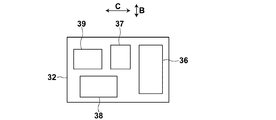
- FIG. 10 Schematic showing another example of the arrangement state of a plurality of circuits in the main body
- the perspective view which shows another example of the wheel part which can be applied to the radiographic imaging apparatus of this invention.
- the perspective view which shows the place which has the wheel part of FIG. 10 in another state.
- the side view which shows another example of the radiation source support part which can be applied to the radiographic imaging apparatus of this invention
- the perspective view which shows the front side of an electronic cassette
- the perspective view which shows the back side of an electronic cassette
- the perspective view which shows another example of the radiation source support part which can be applied to the radiographic imaging apparatus of this invention.
- FIG. 18 is a side view illustrating an example of a usage state of the radiographic image capturing apparatus of FIG.
- FIG. 18 is a plan view showing a part of the radiographic apparatus of FIG.
- FIG. 18 is a side view showing a modification of the radiographic image capturing apparatus of FIG.
- the perspective view which shows the example of the use condition of the radiographic imaging apparatus of FIG. The perspective view which shows another example of the use condition of the radiographic imaging apparatus of FIG.
- FIG. 26 is a front view showing a part of the mechanism of the radiographic apparatus of FIG.
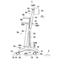
- FIG. 1 is a perspective view showing the overall shape of a radiographic imaging apparatus 1 according to an embodiment of the present invention
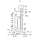
- FIGS. 2 and 3 are side views showing the radiographic imaging apparatus 1 when not in use and in use
- FIG. 4 and FIG. 4 and FIG. 5 are rear views showing the radiographic imaging apparatus 1 when not in use and in use.
- the upper and lower sides in the vertical direction are referred to as “upper” and “lower”, respectively.
- a direction perpendicular to the vertical direction is referred to as a “horizontal” direction.
- the radiographic imaging device 1 of the present embodiment includes a leg portion 10 that can run on the device mounting surface 2 and a main body portion that is held on the leg portion 10. 30, an arm unit 50 as a radiation source support unit connected to the main body unit 30, and a radiation source 70 attached to the tip of the arm unit 50.
- the connection between the main body 30 and the arm 50 may be made directly or indirectly through some member in between.
- the main body 30 is configured such that an element such as a battery, which will be described later, is accommodated in a housing 32 fixed on a substantially thick plate-like base 31.
- a handle 80 for pushing and pulling the radiographic image capturing apparatus 1 is attached to the upper end of the housing 32.
- a holding member 33 is fixed on the base 31, and a console 82 is held above the holding member 33 via a cradle 81.
- the console 82 displays input means 83 such as operation buttons and switches for inputting signals and the like for instructing various operations of the radiographic imaging apparatus 1, the state of the radiographic imaging apparatus 1, input information by the input means 83, and the like.
- Display means 84 for displaying and the like are provided. It is possible to omit the input unit 83 by configuring the display unit 84 as a so-called touch panel and performing a signal input or the like by a touch operation on the touch panel.
- the leg portion 10 is attached to a horizontal base 11, four legs 12 as an example extending outward from the even portion of the base 11, and a wheel mounting portion 12 a on the lower surface of the distal end portion of each leg 12. And a wheel portion 13.
- the base portion 31 described above is held on the pedestal 11 so as to be rotatable about a rotation axis AX1 extending in the vertical direction. Thereby, the main body 30 fixed to the base 31 and an arm 50 described later can rotate relative to the leg 10 around the rotation axis AX1, that is, in a horizontal plane.
- FIG. 6 shows a side shape in the vicinity of the wheel portion 13.
- the wheel portion 13 is constituted by a so-called turning caster that can turn around a turning axis AX2 extending in the vertical direction.
- the wheel unit 13 includes a wheel 14 made of, for example, rubber tires, a wheel holding unit 15 that holds the wheel 14 rotatably about a horizontal axle AX3, and a turning unit 16 integrated with the wheel holding unit 15.
- the turning part 16 is attached to the wheel attachment part 12a of the leg 12 so as to be turnable around the turning axis AX2.
- the turning axis AX2 is set at a position offset from the axle AX3 in the horizontal plane. Therefore, if the leg part 10 is moved in one horizontal direction, the turning part 16 turns so that the turning axis AX2 is located on the front side and the wheel 14 is located on the rear side in the one direction, and the wheel 14 is free. Can be rotated. Therefore, if an operator such as a radiographer holds the handle 80 and pushes or pulls the radiographic image capturing apparatus 1, the radiographic image capturing apparatus 1 can be easily and quickly moved in an arbitrary direction.
- the four wheel portions 13 are in a plan view state, that is, a state in which each turning axis AX2 is positioned at one common rectangular corner in a state of being projected onto the device placement surface 2. Is arranged. Therefore, it is possible to rotate the entire leg portion 10 in the horizontal plane, that is, on the device mounting surface 2 around the vertical line passing through the rectangular center of gravity. When the leg portion 10 rotates in this way, the four wheel portions 13 travel while drawing an arc so as to follow a common circle.
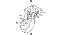
- FIG. 10 shows the state of the wheel unit 90 when the brake is released, and FIG. 11 shows that the brake is operated. The state of the wheel part 90 at the time is shown.
- the wheel portion 90 includes a wheel 91 made of, for example, rubber tires, a wheel holding portion 93 that rotatably holds the wheel 91 around the axle 92, and a wheel holding portion 93 that is turnable.
- a mounting seat 94, a crank-like brake lever 95 held by the wheel holding portion 93, and a leaf spring 96 are provided.
- the brake lever 95 is held by the wheel holding portion 93 so as to be rotatable around an axis on the base end side (right end side in FIGS. 10 and 11).
- the wheel part 90 provided with the brake means as described above is applied to the leg part 10, the wheel part 91 is moved to move the radiation image capturing apparatus 1 to a predetermined position, and then the wheel 91 is braked. Therefore, it is possible to prevent the radiographic image capturing apparatus 1 from moving carelessly.
- a turning caster there is provided a turning caster provided with a brake means for preventing the turning portion from turning around a turning axis (AX2 in the example of FIG. 6). If such a turning caster is applied, it is possible to prevent the radiographic imaging apparatus 1 from moving carelessly by turning the turning portion while allowing the wheel to rotate.
- a wheel portion having such a brake means it is possible to apply a wheel portion capable of braking both the rotation of the wheel and the turning of the turning portion. It is.
- a button or lever installed in the vicinity of the handle 80 may be operated.
- the moving speed of the wheel portion 13 may be detected, and when the detected moving speed exceeds a certain set speed, the wheel portion 13 may be automatically braked. Further, when the detected moving speed exceeds a certain set speed, an alert by an alarm sound or blinking of a lamp may be generated to alert the user of the apparatus. Such an alert may be generated only, or the brake may be applied together therewith.
- the wheel unit 13 may be braked automatically. And when applying the brake to the wheel part 13 automatically as mentioned above, in order to prevent the radiographic imaging device 1 from falling down, the wheel part 13 is gradually decelerated and then the brake is applied completely. It is desirable to do. Further, when the brake is automatically applied to the wheel portion 13, it is desirable to apply the brake to the four wheel portions 13 in the same manner.
- the wheel unit 13 may be automatically braked and locked. In that case, it is desirable that a certain operation immediately before driving the radiation source 70 is detected, and the wheel unit 13 is automatically braked when it is detected.
- the operation include a release operation of a camera that performs optical image shooting for confirming the radiation irradiation range.
- FIG. 7 is a side view showing the main body 30 in a partially broken view.
- the housing 32 constituting the main body 30 is formed in a substantially thin rectangular parallelepiped shape, and an opening (not shown) is formed on the front surface thereof, that is, the surface on which the handle 80 protrudes. The opening is closed by a lid 32a.
- the casing 32 constituting the main body 30 is fixed to the base 31 in an inclined state so that the upper end 32b is closer to the radiation source 70 than the lower end 32c.
- the arrow A shown in FIG. 7 corresponds to the arrow A in FIG. 1.
- the radiation source 70 is located on the front side of the arrow A with respect to the housing 32. become.
- the housing 32 may be configured separately from the base 31 and then fixed to the base 31, or may be formed integrally with the base 31 from the beginning.
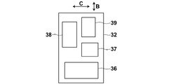
- a DC power supply circuit 37 In the housing 32, in addition to the battery 36 for driving the radiation source 70, a DC power supply circuit 37, a drive control circuit 38, and an inverter (DC-AC conversion circuit) 39 are accommodated. These circuits 37 to 39 divided into blocks are known circuits relating to driving of the radiation source 70, and Japanese Patent Application Laid-Open No. 2000-127834 shows an example thereof.
- the battery 36 and the circuits 37 to 39 can be exchanged, maintained, inspected, and repaired through the opening with the lid 32a opened.
- the arm portion 50 protrudes in one horizontal direction (arrow A direction) with respect to the main body portion 30, but all of the circuits 37 to 39 divided into blocks are described above. They are arranged side by side in the direction crossing the arrow A direction. More specifically, as shown in a schematic arrangement state in FIG. 8, the circuits 37 to 39 are arranged side by side in an arrow B direction intersecting with the arrow A direction and in an arrow C direction also intersecting with the arrow A direction.
- the arrow B direction and the arrow C direction are respectively a vertical direction and a horizontal direction of the casing 32 which is formed into a substantially thin rectangular parallelepiped shape.
- the casing 32 that is, the main body is arranged.
- the portion 30 can be formed thinner.
- the battery 36 is also arranged side by side in the direction of the arrow B together with the circuits 37 to 39, which is more advantageous for forming the main body 30 thin.
- the casing 32 has a shape that is longer in the vertical direction than in the horizontal direction.
- the main body 30 can be formed thin by arranging the battery 36 and the circuits 37 to 39 side by side in the direction intersecting the arrow A direction.
- the battery 36 and the circuits 37 to 39 may be arranged side by side only in the direction of arrow B or in the direction of arrow C.
- a base portion 35 of a rod-like auxiliary leg 34 is attached to the side surface of the holding member 33 so as to be rotatable around a rotation axis AX6.
- the holding member 33 is provided with a slit 33a extending inward from the side surface. For example, an electronic cassette described later can be stored in the slit 33a.
- the leg portion 10 can be turned on the apparatus mounting surface 2 so that the four wheel portions 13 follow a common circle.
- the radiographic image capturing apparatus 1 can be turned using the legs 10 in order to change the traveling direction or to direct the radiation source 70 in a desired direction. It is. That is, the turning of the leg portion 10 in which the four wheel portions 13 follow different circles around a vertical line that is not inside the four wheel portions 13 in a plan view is a large turn. It turns. Note that the above-mentioned “smallest turn” is performed when the leg portion 10 turns so that at least two wheel portions 13 follow a common circle.
- FIG. 12 shows the main body 30 and the base 31 on the leg 10 in a plan view. As shown here, the main body 30 exists in a circular locus C2 drawn by the outermost end of the leg 10. Similarly, the base 31 is also present in the circular locus C2.
- the device user when turning the radiographic imaging device 1 in the smallest turn in order to change the direction of the radiation source 70, the device user will prevent the outermost end of the leg 12 from hitting anything. If care is taken, it is possible to avoid hitting the main body 30 or the base 31 with anything.
- the main body 30 has a length L1 in a direction (arrow A direction) in which the arm 50 protrudes from the main body 30 in a plan view, and a direction perpendicular to the direction (arrow B direction). ) Is shorter than the length L2.
- the radiographic imaging apparatus 1 is slim and does not occupy a large space when the arm part 50 is housed in the cylindrical member 51 with the shortest arm part 50 as will be described later. It can be of shape.
- the length L1 is preferably shorter than 1/3 of the length L2.
- the main body 30 can rotate relative to the leg 10 around the rotation axis AX1, but it is desirable to provide a locking means for preventing this rotation.
- a locking means in conjunction with a brake operation means (for example, the brake lever 95 in FIG. 10) for applying a brake to the wheel portion 13, when the brake is applied to the wheel portion 13, the main body portion 30 is simultaneously provided.
- the structure which locks rotation of this is preferable. Or the thing of the structure which locks rotation of the main-body part 30 by single operation may be sufficient. If such a locking means is provided, the radiation source 70 is rotated when the radiation source 70 can be rotated around the rotation axis AX9 (see FIG. 16) with respect to the arm unit 50 as described later. It is possible to prevent the main body 30 from rotating together.
- the arm portion 50 is provided with a slit 51a extending in a cylinder axis direction in a part of a substantially cylindrical member, and has a substantially “C” -shaped cross-sectional shape, and the cylindrical member.
- a main body side arm 52 (a main body side portion of the arm portion) that can be accommodated in the cylinder 51 so as to be movable in the cylinder axis direction, and a radiation source side arm that can be accommodated in the cylindrical member 51 so as to be movable in the cylinder axis direction (Radiation source side portion of the arm portion) 53.
- the cylindrical member 51 is fixed on the base 31 in a state inclined in substantially the same direction as the case 32 inclined as described above.
- the cylindrical member 51 may have a substantially “C” -shaped cross-sectional shape as described above, or may have a cylindrical or rectangular tube shape, or a cross-sectional shape in which two arcs face each other. It may be a half-divided shape or the like.
- the lower end portion of the radiation source side arm 53 is connected to the upper end portion of the main body side arm 52 via the turning holding mechanism 54 so as to be turnable around the turning axis AX4.
- the turning axis AX4 is an axis extending in the horizontal direction.
- the radiation source side arm 53 turns around the turning axis AX4 in a direction in which the angle formed with the main body side arm 52 changes.
- the turning holding mechanism 54 holds both the radiation source side arm 53 and the body side arm 52 so as to turn through a friction mechanism. Accordingly, the radiation source side arm 53 can be turned by applying a strong external force to some extent, and does not turn unless an external force is applied, and maintains a relative angle with respect to the main body side arm 52.
- the main body side arm 52 incorporates a cylinder (not shown) that constitutes a gas spring, and together with a piston rod 55 combined with the cylinder, constitutes a main body side portion of the arm portion.
- the gas spring basically includes the cylinder in which gas is sealed, a piston that defines the inside of the cylinder into an upper chamber and a lower chamber, a communication path that connects the upper chamber and the lower chamber, and An opening / closing valve for opening and closing the passage, an operating lever for operating the opening / closing valve, and a piston rod 55 having an upper end coupled to the piston are configured.
- the gas spring having the above configuration is widely applied as a height adjusting mechanism in a chair or the like in which the height of the seating surface can be changed.
- the length of the arm portion 50 can be changed.
- the main body side portion of the arm portion consisting of the main body side arm 52 and the piston rod 55
- the main body side arm 52 and the piston rod 55 can be extended and contracted.
- the operation lever when the operation lever is pulled to keep the on-off valve open, the upper chamber and the lower chamber communicate with each other so that gas can flow between the two chambers.
- the main body side arm 52 can be relatively moved. Therefore, if the main body side arm 52 is pushed downward in the cylindrical member 51 by applying a certain amount of force, the entire main body side arm 52 is accommodated in the cylindrical member 51 as shown in FIG. In this state, a part of the radiation source side arm 53 is also accommodated in the cylindrical member 51 in a state where the longitudinal direction is aligned with the main body side arm 52. In this way, when the main body side arm 52 and the radiation source side arm 53 are accommodated in the cylindrical member 51, the turning holding mechanism 54 moves in the slit 51 a of the cylindrical member 51.
- the arm unit 50 When the radiographic imaging device 1 is not used, the arm unit 50 is in the state shown in FIG. Under this state, a part of the radiation source side arm 53 is located in the cylindrical member 51, and therefore it is impossible for the radiation source side arm 53 to turn around the turning axis AX4. That is, in the present embodiment, the cylindrical member 51 serves as a turning restricting means for making the turning of the radiation source side arm 53 impossible when the main body side portion of the arm portion 50 is shorter than a predetermined length. .
- the “predetermined length” in this case is the length of the main body side portion of the arm portion 50 (main body) that slightly brings the lower end of the radiation source side arm 53 out of the cylindrical member 51.
- the on-off valve When the operation lever is released after the state of FIG. 4 is reached, the on-off valve is closed and the gas flow is restricted, so that the state is maintained. Thereafter, when the on-off valve is opened by operating the operation lever, the main body side arm 52 can move relative to the piston rod 55 as described above, and the repulsive force of the gas compressed in the upper chamber The main body side arm 52 moves up in the cylindrical member 51. At this time, the main body side arm 52 can rise to a position where the upper end protrudes from the cylindrical member 51 as shown in FIG. In this state, the entire source-side arm 53 also comes out of the cylindrical member 51, so that the source-side arm 53 can turn around the turning axis AX4.
- the on-off valve When the on-off valve is opened as described above and the main body side arm 52 is raised in the cylindrical member 51, if the operation lever is released and the on-off valve is closed, the gas flow is The main body side arm 52 is restricted and stops at the position at that time. In this way, the length by which the main body side arm 52 projects from the cylindrical member 51, that is, the total length of the arm portion 50 can be adjusted.
- the radiation source 70 is configured by housing, for example, an X-ray tube, a booster circuit, a cooling means for cooling the X-ray tube, and the like in a housing.
- the radiation source 70 is attached to the tip of the radiation source side arm 53 described above via a support member 71 so as to be swingable around the swing axis AX5.
- the rocking of the radiation source 70 is rocking in a direction in which the elevation angle of the radiation emitting axis RC changes as indicated by an arrow F in FIG. If the radiation source 70 can be swung in this way, it is possible to take a radiation image with respect to subjects at various positions by changing the direction of the radiation emission axis RC.
- the rocking position of the radiation source 70 that can be swung can be fixed by operating the lock lever 72.
- the radiation source 70 takes a rocking position in which the radiation output axis RC faces downward as compared with the case where the radiation source 70 is fixed by the action of its own weight. Yes.
- This downward swing position is most preferably the vertical swing position. If configured as described above, for example, after radiographic imaging of the subject is completed, the radiographic imaging device 1 is moved laterally away from the subject, and then the radiation is accidentally irradiated toward the subject. Can be prevented.
- radiographic imaging by the radiographic imaging apparatus 1 having the above configuration will be described.
- the radiographic image capturing apparatus 1 is carried to the use position while traveling on the apparatus mounting surface 2 such as a hospital floor by the wheel section 13 of the leg section 10 in the non-use state shown in FIG.
- the radiographic imaging device 1 can move in the front-rear and left-right directions, and can also move so as to make a large curve. It is also possible to swivel, so that it can be quickly brought to the use position with a small turn.
- the radiographic image is taken on a subject H lying on a supine table 3 such as a bed as shown in FIG.
- the radiographic imaging device 1 can be moved in the height direction of the subject H like a crab walking by the wheel unit 13 formed of a turning caster. It is. Thereby, the radiographic imaging device 1 can be easily set at the optimum position.
- the radiographic imaging apparatus 1 since the main body 30 is generally thin as described above, and the holding member 33 is also thin, the radiographic imaging apparatus 1 has a narrow space, for example, between the beds. You can easily get into. Since the main body 30 and the holding member 33 are generally thin, the radiographic imaging apparatus 1 is set at a position very close to the bed while inserting the leg 10 into the space under the bed. It becomes easy. If this is the case, the position adjustment of the radiation source 70 by expanding and contracting and turning the arm unit 50 can be reduced, and the time required for imaging can be shortened from that point.
- the main body side arm 52 of the arm unit 50 is extended to an arbitrary position protruding on the cylindrical member 51 as described above.
- the radiation source side arm 53 of the arm unit 50 is pivoted about the pivot axis AX4 to set the radiation source 70 at the optimum position, and the radiation source 70 is pivoted about the pivot axis AX5 to emit the radiation output axis.
- RC is set to the optimal orientation.
- the base 31 holding the arm part 50 is rotatable about the rotation axis AX1 on the leg part 10, the direction of the arm part 50 is changed by this rotation, It is also possible to adjust the position and orientation of the radiation source 70.
- the radiation source side arm 53 of the arm unit 50 cannot be turned until the main body side arm 52 extends to a position where the main body side arm 52 protrudes above the cylindrical member 51 by the action of the cylindrical member 51 as described above. Therefore, it is possible to prevent a problem that the radiation source side arm 53 is turned in a state where the radiation source 70 is at a relatively low position and the radiation source 70 hits the subject H. Further, since the arm portion 50 generally protrudes in a direction (arrow A direction) that is closer to the subject H than the main body portion 30, the radiation source 70 can be opposed to the subject H at a position far from the main body portion 30. It becomes possible to arrange.
- the rod-like auxiliary leg 34 is rotated around the rotation axis AX6, and the tip is brought into contact with the apparatus mounting surface 2 as shown in FIG.
- a non-slipable member such as rubber is attached to the tip of the auxiliary leg 34 to prevent slipping.
- the auxiliary leg 34 in this state becomes a so-called “stretching rod” to prevent the radiographic imaging apparatus 1 from falling over to the distal end side of the radiation source side arm 53 where the heavy radiation source 70 is held.
- an outrigger-like member for preventing the fall of a crane truck is accommodated in the holding member 33, and the member is pulled out in the direction of arrow A for use in radiographic imaging. Also good.
- radiographic images are taken by placing, for example, an electronic cassette 110 described later below the subject H, and irradiating the electronic cassette 110 through the subject H with radiation (for example, X-rays) R emitted from the radiation source 70.
- radiation for example, X-rays
- a command for driving the radiation source 70 is issued using the console 82.
- a conventionally known storage phosphor sheet IP: Imaging Plate
- a cassette in which an X-ray silver salt film is housed in a housing may be used.
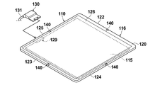
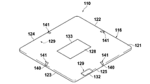
- the electronic cassette 110 will be briefly described with reference to FIGS. FIG. 14 and FIG. 15 respectively show the external appearance of the electronic cassette 110 viewed from the front side and the back side.
- the electronic cassette 110 of this example is used for, for example, medical X-ray imaging, and includes an image detection unit 115 that detects a transmitted X-ray image of the subject H based on the X-rays transmitted through the subject, and an image detection unit 115. And a portable casing 116 that accommodates the container.
- the image detection unit 115 includes a scintillator (phosphor) that converts incident X-rays into visible light, and a TFT (Thin Film Transistor) active matrix substrate.
- a scintillator phosphor
- TFT Thin Film Transistor
- the housing 116 is provided with a gate driver that applies a gate pulse to the gate of the TFT to switch the TFT, and converts the charge accumulated in the pixel into a voltage signal representing an X-ray image.
- a signal processing circuit for output, a gate driver, a control unit for controlling driving of the signal processing circuit, and the like are incorporated.
- the housing 116 has a rectangular parallelepiped shape including a front surface 120 on which X-rays are incident, a rear surface 121 facing the front surface 120, and four side surfaces 122, 123, 124, and 125.
- the housing 116 is formed of, for example, a conductive resin, and also functions as an electromagnetic shield that prevents electromagnetic noise from entering the electronic cassette 110 and radiating electromagnetic noise from the electronic cassette 110 to the outside.
- the casing 116 has a size conforming to an international standard ISO (International Organization for Standardization) 4090: 2001, which is substantially the same as, for example, a film cassette, an IP (Imaging Plate) cassette, or a CR (Computed Radiography) cassette.
- ISO International Organization for Standardization
- a rectangular opening is formed in the front surface 120, and a transmission plate 126 is attached to the opening.
- a resin protective film (not shown) that transmits X-rays is attached to the surface of the transmission plate 126.
- the transmission plate 126 is a plane size slightly larger than the imaging region, and is made of a carbon material that is lightweight, has high rigidity, and has high X-ray transparency.
- the electronic cassette 110 includes a control device that controls the operation of the electronic cassette 110, an antenna that generates radio waves for wirelessly communicating various information such as X-ray images, and an oscillation circuit.
- the electronic cassette 110 is driven by the electric power from the battery 128 and can be used without a so-called cable.
- the electronic cassette 110 includes a female connector 129 for wired communication with a control device (not shown).
- a male connector 130 is connected to the female connector 129.
- One end of a cable 131 for connecting the electronic cassette 110 and the control device to each other by wire is connected to the male connector 130.
- the other end of the cable 131 is connected to a connector (not shown) connected to the control device.
- the female connector 129 is covered and protected by a lid 132 when the male connector 130 is not connected, such as during use of the wireless communication function.
- the electronic cassette 110 receives not only various information but also power supply from the control device via the female connector 129.
- the electronic cassette 110 is driven by the electric power from the control device. It is also possible to charge the battery 128 with electric power from the control device.
- a battery mounting portion 133 is provided in the center portion of the back surface 121.
- a battery 128 that supplies electric power for driving the electronic cassette 110 is detachably attached to the battery attachment portion 133.
- FIG. 15 shows a state where the battery 128 is attached to the battery attachment portion 133.
- the battery mounting portion 133 is a concave portion in which the back surface 121 is recessed toward the front surface 120.
- the battery mounting portion 133 is formed in the same shape and the same size as the planar shape and the planar size of the battery 128 so that the battery 128 can be accommodated with almost no gap.
- the depth of the battery mounting portion 133 from the back surface 121 is also substantially the same as the thickness of the battery 128. Therefore, in the illustrated state where the battery 128 is mounted on the battery mounting portion 133, the upper surface of the battery 128 is exposed from the rear surface 121, and the upper surface of the battery 128 and the rear surface 121 are flush with each other.
- the electronic cassette 110 is provided with four marks 140 and four indicators 141 each composed of a light emitting element such as an LED or an organic EL (Electro-Luminescence) element. These marks 140 and indicators 141 serve to inform the operator of the center position of each side of the rectangular imaging region.
- a light emitting element such as an LED or an organic EL (Electro-Luminescence) element.
- the electronic cassette 110 After the X-ray image information is recorded on the electronic cassette 110, the electronic cassette 110 is connected to an image recording device or an image display device that receives a voltage signal representing the X-ray image, and based on this signal, the transmission of the subject H is transmitted. An X-ray image is recorded or reproduced and displayed.
- the main body side arm 52 and the radiation source side arm 53 of the arm unit 50 shown in FIG. 3 and the like are connected via a gas spring 97 as shown in FIG. It is desirable not to face downward from the state. By doing so, when the radiation source 70 (see FIG. 3) held at the distal end of the radiation source side arm 53 is placed above the subject H and the radiography is performed, the radiation source side arm 53 is inadvertent. It is possible to avoid a situation in which the radiation source 70 hits the subject H by turning downward.
- FIG. 13 the same elements as those in FIGS. 1 to 12 described above are denoted by the same reference numerals, and description thereof will be omitted unless necessary (hereinafter the same). .
- one end portion and the other end portion of the gas spring 97 are respectively connected to the holding portion 98 fixed to the main body side arm 52 and the holding portion 99 fixed to the radiation source side arm 53. It is rotatably held around the rotation axes AX7 and AX8.
- the holding portions 98 and 99 projecting from the arms 52 and 53, respectively. Is positioned in the slit 51 a of the tubular member 51. As a result, even if these protruding holding portions 98 and 99 are provided, the arms 52 and 53 can be accommodated in the cylindrical member 51.
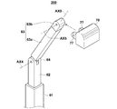
- the arm part 200 shown in FIG. 16 includes a cylindrical outer member 61 whose base end portion is connected to the main body part 30 (see FIG. 2 and the like), and a cylindrical shaft in the outer member 61. It is comprised from the inner member 62 which was accommodated so that the movement to the direction was possible, and connected the source side arm 63 to the front end side so that turning was possible.
- the radiation source side arm 63 is connected to the inner member 62 via a connecting portion 64 so as to be rotatable about a turning axis AX4.
- the cylindrical outer member 61 is formed in a rectangular tube shape as an example.
- the inner member 62 is accommodated with respect to the outer member 61 via an appropriate friction mechanism or a gas spring as described above. Therefore, the inner member 62 can be stopped at an arbitrary position in the cylinder axis direction with respect to the outer member 61 to maintain the state.
- a part of the radiation source side arm 63 enters the outer member 61 with the inner member 62 and the longitudinal direction aligned.
- the radiation source side arm 63 cannot turn around the turning axis AX4.
- the source-side arm 63 cannot be swiveled under a state where the main body side portion of the arm portion composed of the outer member 61 and the inner member 62 is shorter than a predetermined length.
- the length of the outer member 61 is set to the above-mentioned “predetermined length”, and the outer member 61 constitutes the turning restricting means.
- the length of the main body side portion of the arm portion compared with the “predetermined length” is the length from the proximal end of the outer member 61 to the distal end of the inner member 62.
- this rule is the same when the tip of the inner member 62 is located in the outer member 61.
- the outer member 61 constituting the main body side portion of the arm portion is disposed so that the longitudinal direction is perpendicular to the device mounting surface 2 (see FIG. 2 and the like).
- the radiation source side arm 63 is comprised from the comparatively long elongate part 63a and the comparatively short front-end
- the distal end portion 63b is connected to the elongated portion 63a so as to be rotatable around a rotation axis AX9 parallel to the longitudinal direction of the radiation source side arm 63.
- the radiation source 70 is connected to the distal end portion 63b so as to be swingable around the swing axis AX5 in a state where the distal end portion 63b is sandwiched between the two support members 77.
- the radiation source 70 attached to the radiation source side arm 63 as described above can further rotate around the rotation axis AX9 together with the distal end portion 63b in addition to the above-described swinging, various radiation irradiation directions can be set. This is advantageous.
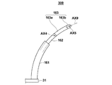
- the arm portion may have a curved shape.
- FIG. 17 is a side view showing an example of the arm portion having such a curved shape.
- the arm part 300 in FIG. 17 is the same as the outer member 61, the inner member 62, the long part 63a, and the tip part 63b in the arm part 200 in FIG. And has a long portion 163a and a tip portion 163b.
- the long arm 163a and the tip 163b constitute a radiation source side arm 163.
- the structure for attaching the radiation source 70 to the tip 163b is the same as that in the arm 200 of FIG.
- the distal end portion 163b can be rotated around a rotation axis AX9 parallel to the longitudinal direction of the radiation source side arm 163, as in the arm portion 200 of FIG.
- the “longitudinal direction of the radiation source side arm 163” in this case is more precisely the tangential direction of the end of the curved arm portion on the radiation source mounting side.
- the “longitudinal direction” is defined as not including the object in the arm portion.
- a height adjustment mechanism capable of adjusting the height from the wheel portion to the radiation source support portion is further provided.
- a height adjustment mechanism capable of adjusting the height from the wheel portion to the radiation source support portion.
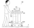
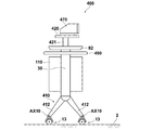
- a radiographic image capturing apparatus 400 shown in FIG. 18 includes a leg portion 410, a main body 30 held on the leg portion 410, a handle 480 for pushing and pulling the radiographic image capturing apparatus 400, a console 82, and the like. , A radiation source 470, a support base 420 that supports the radiation source 470, and an elevating mechanism 421 that is fixed to the upper end and can be moved up and down with respect to the main body 30.
- the main body 30 holds the electronic cassette 110 so as to be removable.
- the main body 30 and the console 82 are basically the same as those shown in FIG.
- the electronic cassette 110 is the same as that described above, but in this embodiment, the electronic cassette 110 is held in the main body 30 in a different orientation from that in the radiographic imaging apparatus 1 of FIG. It has become.
- the support table 420 is a radiation source support unit in the present embodiment, and the radiation source 470 is mounted on the support table 420 so as to emit radiation in the lateral direction.
- the leg part 410 is composed of four legs 412 (only two are shown in the figure) and a wheel part 13 attached to the lower end of each leg 412.
- the wheel portion 13 is basically the same as that shown in FIG. 1, but here is attached to the leg 412 so as to be swingable around the swing axis AX10.
- the four legs 412 are interlocked with each other so that the angle with respect to the horizontal direction can be adjusted.
- the swinging positions of the legs 412 can be fixed by a fixing lever or the like (not shown) in a state where the angle is arbitrarily adjusted.
- the radiographic image capturing apparatus 400 of the present embodiment having the above-described configuration is capable of running and moving on the apparatus mounting surface 2 when the apparatus user U holds and pushes the handle 480 and pulls it. Thus, when the radiographic image capturing apparatus 400 is moved, the elevating mechanism 421 is lowered to, for example, the lowest position.
- the radiation image capturing apparatus 400 is used in an emergency medical institution or the like, for example, to capture a chest standing image of a subject H sitting on an imaging table 450 as shown in FIG. That is, in this case, the radiation R emitted from the radiation source 470 in the lateral direction passes through the subject, and a transmitted radiation image of the subject H by the radiation R is captured and recorded in the electronic cassette 110.
- the elevating mechanism 421 is moved up by an appropriate distance, and the radiation source 470 is set to an optimum position with respect to the height position of the subject H.
- the angles of the four legs 412 are changed in a direction in which the lower ends approach each other as shown in FIG. Thereby, the height from the wheel part 13 to the support stand 420 becomes longer, and the radiation source 470 is set to a higher position.
- the radiographic image capturing apparatus 400 of the present embodiment is used when the apparatus user U moves by pushing or pulling the radiographic image capturing apparatus 400. It is also possible to change the height from the wheel portion 13 to the handle 480 by changing the angle of the four legs 412 in order to facilitate the operation according to the height of the wheel.
- the two legs 412 that can change the angle with respect to the horizontal direction and the two mechanisms of the elevating mechanism 421. Is applied, but only one of them may be applied.
- a radiation source 470 is mounted on the support base 420 so as to emit radiation R downward after applying a mechanism having a relatively long lifting stroke as the lifting mechanism 421, a chest image or abdominal part of a subject in a lying position is provided. It is also possible to take an image. In that case, it is also possible to set the distance SID (Source) Image Distance) between the radiation source and the radiation detector to a desired value by operating the height adjusting mechanism.
- SID Source
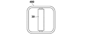
- FIG. 21 shows a planar shape of the handle 480.
- the handle 480 has a shape that surrounds the entire circumference of the main body 30. If the handle 480 has such a shape, the radiographic image capturing apparatus 400 can be pushed and pulled from any of the front, rear, left, and right sides of the main body 30. , Mobility becomes higher.
- FIG. 22 shows a state where the electronic cassette 110 is not held in the main body 30.
- a radiographic imaging apparatus 500 shown in FIG. 23 includes a leg lower part 510, a leg upper part 511 fixed on the leg lower part 510, a main body part 530 held on the leg upper part 511, a console 82, A main body side arm 552 attached to the main body portion 530 via a hinge, a radiation source side arm 553 attached to the main body side arm 552 via a hinge, and attached to the radiation source side arm 553 via a hinge.
- a radiation source 570 is attached to the main body portion 530 via a hinge, a radiation source side arm 553 attached to the main body side arm 552 via a hinge, and attached to the radiation source side arm 553 via a hinge.
- the main body 530 is of a horizontal type. Further, the main body side arm 552 and the radiation source side arm 553 constitute a radiation source support section in the present embodiment.
- the leg lower part 510 and the leg upper part 511 together with the wheel part 13 attached to the lower end of the leg lower part 510 constitute a leg part in this embodiment.
- the leg lower portion 510 includes a connecting portion 510a extending in the lateral direction, four lower outer cylinders 510b connected obliquely to the connecting portion 510a, and lower inner cylinders 510c inserted through the respective lower outer cylinders 510b. It is configured.
- the leg upper part 511 is comprised from the upper outer cylinder 511a and the upper inner cylinder 511b by which this upper outer cylinder 511a was penetrated.
- the lower end of the upper inner cylinder 511b is fixed to the connecting portion 510a.
- the wheel portion 13 is attached to the lower end of the lower inner cylinder 510c.
- the main body 530 is fixed to the upper end of the upper outer cylinder 511a.
- the insertion length of the upper inner cylinder 511b with respect to the upper outer cylinder 511a can be adjusted, and the both cylinders 511a and 511b constitute a telescopic cylinder mechanism. That is, when the insertion length is adjusted, the entire length of the upper outer cylinder 511a and the upper inner cylinder 511b expands and contracts. Further, the insertion length of the lower inner cylinder 510c with respect to the lower outer cylinder 510b can also be adjusted, and the both cylinders 510b and 510c constitute an extendable cylinder mechanism. That is, when the insertion length is adjusted, the entire length of the lower outer cylinder 510b and the lower inner cylinder 510c expands and contracts.
- both the cylinders 511a and 511b constituting the leg upper part 511 are connected through, for example, a gas spring as described above. Therefore, the upper inner cylinder 511b can be stopped at an arbitrary position in the cylinder axis direction with respect to the upper outer cylinder 511a, and the state can be maintained.
- the lower inner cylinder 510c in the leg lower part 510 can maintain the cylinder axial position with respect to the lower outer cylinder 510b, for example, by tightening a set screw.
- the main body side arm 552 and the radiation source side arm 553 are extended as shown in FIG. 24 and FIG.
- the source 570 is set to emit radiation downward or laterally.
- the above-described SID is adjusted.
- the height position of the radiation source 570 is adjusted to the height of the subject. Therefore, as shown in FIG. 25, the entire length of the upper outer cylinder 511a and the upper inner cylinder 511b can be appropriately extended. Thereby, the radiation source 570 can be set at a higher position.
- the entire length of the lower outer cylinder 510b and the lower inner cylinder 510c can be appropriately extended to set the radiation source 570 at a higher position.
- a radiographic image capturing apparatus 600 shown in FIG. 26 is fixed on four wheel parts 13 (only three are shown in the figure), a base part 631 constituting a leg part together with the wheel parts 13, and the base part 631.
- a main body 630 an arm support 632 attached to the main body 630 via an elevating mechanism described later, a radiation source 670, a radiation source holding member 671 that holds the radiation source 670, and the radiation source holding member
- the first arm 672 is swingable in the direction of arrow K with respect to the second arm 674 by the action of the first joint 673.
- the second arm 674 is swingable in the direction of arrow L with respect to the arm support portion 632 by the action of the second joint 675.
- the height position of the radiation source 670 can be changed by swinging the first arm 672 and the second arm 674 as described above.
- the second joint 675 is attached to the arm support 632 so as to be rotatable in the direction of arrow S in the horizontal plane.
- the arm support 632 is connected to a lifting mechanism (not shown) disposed in the main body 630.
- the elevating mechanism 640 is, for example, a pantograph type, and includes an upper end member 641 to which the arm support portion 632 is connected, a lower end member 642 fixed to, for example, the base 631 in the main body portion 630, and an upper end member 641. It is composed of a plurality of pantograph arms 643 that connect the lower end member 642.
- the elevating mechanism 640 by extending and contracting the pantograph arm 643, the vertical position of the upper end member 641, that is, the height position of the arm support portion 632 connected thereto can be changed.
- the height position of the arm support portion 632 When the height position of the arm support portion 632 is changed as described above, the heights of the first arm 672 and the second arm 674 in FIG. 26 are changed, and consequently the height position of the radiation source 670 is changed.
- the height position of the radiation source 670 is changed as described above to thereby change the radiation source.
- the distance SID Source Image Distance
- the height position of the arm support portion 632 can be maintained at an arbitrary position, for example, by tightening a set screw for suppressing the vertical movement of the upper end member 641.
- the second joint 675 is attached to the arm support 632 so as to be rotatable in the direction of the arrow S in FIG. 26, so that the first arm 672 and the second arm The position of the radiation source 670 can be changed by swinging 674 in this direction.
- FIG. 28 shows a state in which the omni wheel 700 is attached to the leg 12 of the radiographic imaging apparatus 1 shown in FIG. 1 as an example.
- the omni wheel 700 is one of omnidirectional wheels, and is attached to the axle 701 and can rotate forward and backward around the rotation axis AX11, and a plurality of attached to the outer periphery of the rotation body 702. And a roller 703.
- a roller 703 for example, a barrel-type roller is applied.
- seven rollers 703, that is, a total of 14 rollers 703 are attached to the left and right.
- Each of the seven rollers 703 on the left and right sides is attached to the rotating body 702 so as to be able to rotate forward and backward about a rotation axis AX12 extending in the tangential direction of one circle coaxial with the rotation axis AX11.
- the seven rollers 703 on one side of the left and right are respectively disposed at positions facing the gaps between the seven rollers 703 on the other side of the left and right.
- the omni wheel 700 having the above configuration is attached to the leg 12 via a bearing portion 704 that receives the axle 701.
- the rotating body 702 and the 14 rollers 703 constitute one rotating wheel. That is, when a force acting in the direction of the arrow P in the figure is applied to the radiographic imaging device having the legs 12, the wheel composed of the rotating body 702 and the roller 703 has the 14 rollers 703 as the outer peripheral surface of the wheel and the rotation axis AX11. To facilitate the movement of the leg 12, that is, in the direction of the arrow P of the radiographic apparatus. When a force acting in the direction of arrow Q in the figure is applied to the radiographic imaging apparatus having the legs 12, the grounded roller 703 rotates around the rotation axis AX12, and the leg 12, that is, the radiographic image. The movement of the photographing apparatus in the arrow Q direction is facilitated.
- a Mecanum wheel disclosed in Japanese Patent Laid-Open No. 2013-081659 is also applicable.
Landscapes
- Health & Medical Sciences (AREA)
- Life Sciences & Earth Sciences (AREA)
- Engineering & Computer Science (AREA)
- Medical Informatics (AREA)
- Physics & Mathematics (AREA)
- Biomedical Technology (AREA)
- Molecular Biology (AREA)
- General Health & Medical Sciences (AREA)
- Nuclear Medicine, Radiotherapy & Molecular Imaging (AREA)
- Optics & Photonics (AREA)
- High Energy & Nuclear Physics (AREA)
- Animal Behavior & Ethology (AREA)
- Public Health (AREA)
- Heart & Thoracic Surgery (AREA)
- Radiology & Medical Imaging (AREA)
- Surgery (AREA)
- Pathology (AREA)
- Biophysics (AREA)
- Veterinary Medicine (AREA)
- Mechanical Engineering (AREA)
- Computer Networks & Wireless Communication (AREA)
- General Physics & Mathematics (AREA)
- Spectroscopy & Molecular Physics (AREA)
- Automation & Control Theory (AREA)
- Robotics (AREA)
- Apparatus For Radiation Diagnosis (AREA)
Abstract
Le problème à résoudre dans le cadre de la présente invention consiste à configurer un dispositif d'imagerie radiographique, pour lequel une source de rayonnement est retenue par une partie de support de source de rayonnement de telle sorte que le dispositif d'imagerie radiographique puisse être rapidement transporté dans un état dans lequel il est facilement déplacé jusqu'à sa position d'utilisation. La solution consiste en un dispositif d'imagerie radiographique qui est pourvu : d'une partie patte (10) ayant au moins trois parties roues (13) et qui peut se déplacer sur une surface de montage de dispositif par l'utilisation de roues (14); d'une partie corps principal (30) retenue sur la partie patte (10); d'une partie bras (50) en tant que partie de support de source de rayonnement raccordée à la partie corps principal (30); d'une source de rayonnement (70) fixée à la partie bras (50); d'une batterie destinée à alimenter la source de rayonnement (70), la batterie étant logée dans la partie corps principal (30); et d'un circuit impliqué dans l'alimentation de la source de rayonnement (70), le circuit étant logé dans la partie corps principal (30), les parties roues (13) étant composées de roulettes pivotantes.
Priority Applications (3)
| Application Number | Priority Date | Filing Date | Title |
|---|---|---|---|
| CN201680040795.6A CN107835660B (zh) | 2015-07-16 | 2016-05-23 | 放射线图像摄影装置 |
| EP16824019.0A EP3323345B1 (fr) | 2015-07-16 | 2016-05-23 | Dispositif d'imagerie radiographique |
| US15/864,041 US10993682B2 (en) | 2015-07-16 | 2018-01-08 | Radiographic imaging apparatus comprising a leg unit having three or more wheel units |
Applications Claiming Priority (2)
| Application Number | Priority Date | Filing Date | Title |
|---|---|---|---|
| JP2015-141787 | 2015-07-16 | ||
| JP2015141787A JP6145899B2 (ja) | 2015-07-16 | 2015-07-16 | 放射線画像撮影装置 |
Related Child Applications (1)
| Application Number | Title | Priority Date | Filing Date |
|---|---|---|---|
| US15/864,041 Continuation US10993682B2 (en) | 2015-07-16 | 2018-01-08 | Radiographic imaging apparatus comprising a leg unit having three or more wheel units |
Publications (1)
| Publication Number | Publication Date |
|---|---|
| WO2017010033A1 true WO2017010033A1 (fr) | 2017-01-19 |
Family
ID=57757220
Family Applications (1)
| Application Number | Title | Priority Date | Filing Date |
|---|---|---|---|
| PCT/JP2016/002483 Ceased WO2017010033A1 (fr) | 2015-07-16 | 2016-05-23 | Dispositif d'imagerie radiographique |
Country Status (5)
| Country | Link |
|---|---|
| US (1) | US10993682B2 (fr) |
| EP (1) | EP3323345B1 (fr) |
| JP (1) | JP6145899B2 (fr) |
| CN (1) | CN107835660B (fr) |
| WO (1) | WO2017010033A1 (fr) |
Cited By (1)
| Publication number | Priority date | Publication date | Assignee | Title |
|---|---|---|---|---|
| WO2018142557A1 (fr) * | 2017-02-03 | 2018-08-09 | 株式会社島津製作所 | Appareil d'imagerie par rayonnement portatif |
Families Citing this family (11)
| Publication number | Priority date | Publication date | Assignee | Title |
|---|---|---|---|---|
| US10151810B2 (en) * | 2012-06-14 | 2018-12-11 | Mobius Imaging, Llc | Pivoting multi-directional X-ray imaging system with a pair of diametrically opposite vertical support columns tandemly movable along a stationary base support |
| US10987068B2 (en) | 2012-06-14 | 2021-04-27 | Mobius Imaging Llc | Multi-directional x-ray imaging system |
| US10842453B2 (en) * | 2016-02-03 | 2020-11-24 | Globus Medical, Inc. | Portable medical imaging system |
| DE102016013315B4 (de) | 2016-11-08 | 2024-07-11 | RayScan Technologies GmbH | Messsystem und Verfahren zum Betreiben eines Messsystems |
| KR102097747B1 (ko) * | 2018-03-30 | 2020-04-06 | 이병칠 | 의료 중계기용 지그장치 |
| WO2021078304A1 (fr) | 2019-10-24 | 2021-04-29 | Shanghai United Imaging Healthcare Co., Ltd. | Systèmes, procédés et dispositifs de rayonnement |
| JP7222880B2 (ja) * | 2019-12-26 | 2023-02-15 | キヤノン電子管デバイス株式会社 | X線管梱包装置 |
| JP7165158B2 (ja) | 2020-04-13 | 2022-11-02 | 株式会社メディカロイド | 医師側操作装置および手術システム |
| US11690582B2 (en) * | 2020-05-06 | 2023-07-04 | GE Precision Healthcare LLC | Systems and methods for a mobile medical device drive platform |
| KR102838090B1 (ko) * | 2024-10-29 | 2025-07-24 | 제이피아이헬스케어 주식회사 | 개선된 암을 포함하는 의료영상장치 및 의료영상장치의 동작방법 |
| KR102836434B1 (ko) * | 2024-10-29 | 2025-07-21 | 제이피아이헬스케어 주식회사 | 전복을 방지하기 위한 구조를 포함하는 의료영상장치 및 의료영상장치의 동작방법 |
Citations (8)
| Publication number | Priority date | Publication date | Assignee | Title |
|---|---|---|---|---|
| JP2003325497A (ja) * | 2002-05-15 | 2003-11-18 | Aloka Co Ltd | 骨塩量測定装置 |
| JP2005131157A (ja) * | 2003-10-31 | 2005-05-26 | Shimadzu Corp | Cアーム形x線装置 |
| JP2007301284A (ja) * | 2006-05-15 | 2007-11-22 | Aloka Co Ltd | 骨検査システム及び検査部位固定装置 |
| JP2009298280A (ja) * | 2008-06-12 | 2009-12-24 | Mitaka Koki Co Ltd | ベースのストッパ構造 |
| JP2010057546A (ja) * | 2008-09-01 | 2010-03-18 | Canon Inc | X線撮影装置 |
| JP2013503778A (ja) * | 2009-09-08 | 2013-02-04 | コーニンクレッカ フィリップス エレクトロニクス エヌ ヴィ | 双方向運動装置 |
| JP2013146301A (ja) * | 2012-01-17 | 2013-08-01 | Canon Inc | X線撮影装置 |
| JP2014195588A (ja) * | 2013-03-29 | 2014-10-16 | キヤノン株式会社 | 放射線発生用装置及び放射線撮影装置 |
Family Cites Families (87)
| Publication number | Priority date | Publication date | Assignee | Title |
|---|---|---|---|---|
| SE8902831D0 (sv) | 1989-08-25 | 1989-08-25 | Siemens Elema Ab | Viktutjaemningsanordning |
| US5283823A (en) * | 1991-11-27 | 1994-02-01 | X-Cel X-Ray Corporation | Portable radiographic device |
| JPH0576406U (ja) | 1992-03-26 | 1993-10-19 | 株式会社日立メディコ | 移動形x線装置 |
| US6543936B2 (en) * | 2001-04-24 | 2003-04-08 | Daniel Uzbelger Feldman | Apparatus for diagnosis and/or treatment in the field of dentistry using fluoroscopic and conventional radiography |
| WO2005053534A2 (fr) * | 2003-11-26 | 2005-06-16 | Orex Computed Radiography | Radiographie informatisee mobile |
| JP4612832B2 (ja) * | 2004-12-03 | 2011-01-12 | キヤノン株式会社 | 放射線撮影装置及びその制御方法 |
| WO2009104318A1 (fr) * | 2008-02-22 | 2009-08-27 | 株式会社 日立メディコ | Appareil de radiographie mobile |
| JP5367589B2 (ja) * | 2008-02-22 | 2013-12-11 | 株式会社日立メディコ | 移動型x線装置 |
| CN102065768A (zh) * | 2008-07-10 | 2011-05-18 | 株式会社日立医疗器械 | 移动型x射线装置 |
| EP2408375B1 (fr) * | 2009-03-20 | 2017-12-06 | Orthoscan Incorporated | Appareil mobile d'imagerie |
| JP5442307B2 (ja) * | 2009-04-22 | 2014-03-12 | 株式会社日立メディコ | 移動型x線装置 |
| FR2945724B1 (fr) * | 2009-05-22 | 2012-11-16 | Gen Electric | Appareil a rayons x |
| JP5611213B2 (ja) * | 2009-08-28 | 2014-10-22 | 株式会社日立メディコ | 移動型x線装置 |
| CN102038511B (zh) * | 2009-10-23 | 2015-05-13 | Ge医疗系统环球技术有限公司 | X射线成像系统 |
| MX2012004544A (es) * | 2009-11-05 | 2012-07-30 | Es De Electromedicina Y Calidad S A Soc | Dispositivo para desplazamiento lateral. |
| FR2953119B1 (fr) * | 2009-12-01 | 2012-07-27 | Gen Electric | Base mobile et appareil a rayons x monte sur une telle base mobile |
| US8568028B2 (en) * | 2010-04-13 | 2013-10-29 | Carestream Health, Inc. | Mobile radiography unit having collapsible support column |
| US8961011B2 (en) * | 2010-04-13 | 2015-02-24 | Carestream Health, Inc. | Mobile radiography unit having multiple monitors |
| US8672543B2 (en) * | 2010-04-13 | 2014-03-18 | Carestream Health, Inc. | Counterweight for mobile x-ray device |
| WO2011136094A1 (fr) * | 2010-04-26 | 2011-11-03 | 株式会社 日立メディコ | Dispositif mobile à rayons x et procédé de commande d'un dispositif mobile à rayons x |
| US8840304B2 (en) * | 2010-06-14 | 2014-09-23 | General Electric Company | Positioner for ultra-portable imaging system |
| US9044191B2 (en) * | 2010-06-29 | 2015-06-02 | Fujifilm Corporation | Radiographic image capturing apparatus |
| JP5665405B2 (ja) | 2010-07-30 | 2015-02-04 | 富士フイルム株式会社 | 放射線画像撮影システム及び画像表示方法 |
| WO2012032688A1 (fr) * | 2010-09-10 | 2012-03-15 | 株式会社島津製作所 | Dispositif de radiographie mobile |
| CN103220977B (zh) * | 2010-11-18 | 2015-06-17 | 株式会社日立医疗器械 | 移动型x射线装置 |
| US8459868B2 (en) * | 2010-11-23 | 2013-06-11 | General Electric Company | Portable X-ray machine with drive wheel suspension |
| WO2012082799A1 (fr) * | 2010-12-13 | 2012-06-21 | Orthoscan, Inc. | Système d'imagerie fluoroscopique mobile |
| NL2005906C2 (en) * | 2010-12-22 | 2012-06-25 | Nucletron Bv | A mobile x-ray unit. |
| FR2972915B1 (fr) * | 2011-03-24 | 2013-04-19 | Gen Electric | Systeme d'imagerie medicale multiplan |
| US8721176B2 (en) * | 2011-05-06 | 2014-05-13 | General Electric Company | Rechargeable image detector system and method |
| KR102028769B1 (ko) * | 2011-09-12 | 2019-10-04 | 케어스트림 헬스 인코포레이티드 | 이동식 라디오그래피 촬영 장치에 저장된 전기적 그리드 홀더와 감지기들을 위한 충전기 및 이를 이용하기 위한 방법 |
| JPWO2013047438A1 (ja) * | 2011-09-28 | 2015-03-26 | 株式会社日立メディコ | 移動型x線診断装置及び移動型x線診断装置の制御方法 |
| JP2014533188A (ja) * | 2011-11-15 | 2014-12-11 | ソリューションズ フォー トゥモロー エービー | X線画像を生成するための装置、システム及び方法 |
| US9198270B2 (en) * | 2011-11-18 | 2015-11-24 | Virtual Imaging, Inc. | Radiographic imaging apparatus with distributed antenna system |
| US9101316B2 (en) * | 2011-11-30 | 2015-08-11 | General Electric Company | Portable radiation detector and system |
| US9364188B2 (en) * | 2011-12-22 | 2016-06-14 | Shimadzu Corporation | X-ray apparatus for round visit |
| JP5917162B2 (ja) * | 2012-01-19 | 2016-05-11 | キヤノン株式会社 | X線撮影装置 |
| US9078597B2 (en) * | 2012-04-05 | 2015-07-14 | General Electric Company | Mobile x-ray unit with integrated x-ray shield |
| US9693437B2 (en) * | 2012-04-13 | 2017-06-27 | General Electric Company | Systems and methods for controlling X-ray imaging systems |
| US8899834B2 (en) * | 2012-04-18 | 2014-12-02 | General Electric Company | Pivot joint brakes for X-ray positioning system |
| EP2840973B1 (fr) * | 2012-04-24 | 2017-06-28 | Portavision Medical LLC | Procédé et système d'imagerie mobile |
| JP6238611B2 (ja) * | 2012-09-28 | 2017-11-29 | キヤノン株式会社 | 移動型放射線撮影装置、放射線撮影システム、及び制御方法 |
| JP2014083108A (ja) * | 2012-10-19 | 2014-05-12 | Canon Inc | 移動型のx線画像撮影装置 |
| JP6222960B2 (ja) * | 2012-11-12 | 2017-11-01 | キヤノン株式会社 | 放射線発生用装置及び放射線撮影装置 |
| US9649080B2 (en) * | 2012-12-05 | 2017-05-16 | Samsung Electronics Co., Ltd. | X-ray imaging apparatus and method for controlling the same |
| JP2014178308A (ja) | 2013-02-12 | 2014-09-25 | Fujifilm Corp | 電子カセッテ |
| JP2014155620A (ja) * | 2013-02-15 | 2014-08-28 | Canon Inc | 移動型x線発生装置 |
| JP6242060B2 (ja) * | 2013-02-19 | 2017-12-06 | キヤノン株式会社 | 移動型x線撮影装置 |
| JP6065248B2 (ja) * | 2013-02-27 | 2017-01-25 | 株式会社島津製作所 | X線撮影装置 |
| US9456799B2 (en) * | 2013-03-08 | 2016-10-04 | Virtual Imaging, Inc. | Modality with multicomputer system and powering sequence therefor |
| JP2014195590A (ja) * | 2013-03-29 | 2014-10-16 | キヤノン株式会社 | 放射線発生用装置、放射線撮影装置、コンピュータプログラム及び記憶媒体 |
| EP2974659B1 (fr) * | 2013-04-25 | 2017-09-06 | Shimadzu Corporation | Dispositif de collecte d'image radiographique du type mobile |
| JP6200202B2 (ja) * | 2013-04-26 | 2017-09-20 | キヤノン株式会社 | 移動型放射線発生装置及び放射線撮影システム |
| US9480445B2 (en) * | 2013-05-14 | 2016-11-01 | Solutions For Tomorrow Ab | Elevating column and method of controlling elevation thereof |
| CN105050503B (zh) * | 2013-07-04 | 2018-11-27 | 西班牙电子医药质量公司 | 具有伸缩柱的移动式x-射线设备 |
| KR102105853B1 (ko) * | 2013-07-26 | 2020-05-04 | 삼성전자주식회사 | 엑스 선 스티칭 지그 |
| WO2015073105A1 (fr) * | 2013-09-03 | 2015-05-21 | Thomas Welsh | Dispositif d'affichage articulé pour une machine radiographique mobile |
| CN105705095B (zh) * | 2013-09-06 | 2019-10-08 | 株式会社岛津制作所 | 移动式x射线摄影装置 |
| JP6324009B2 (ja) * | 2013-09-12 | 2018-05-16 | キヤノン株式会社 | 放射線発生用装置及び放射線撮影装置 |
| JP6113093B2 (ja) * | 2013-09-17 | 2017-04-12 | 富士フイルム株式会社 | 可搬型放射線撮影装置及び可搬型放射線撮影システム |
| JP6039593B2 (ja) * | 2013-09-17 | 2016-12-07 | 富士フイルム株式会社 | 可搬型放射線撮影装置及び可搬型放射線撮影システム |
| JP6050206B2 (ja) * | 2013-09-17 | 2016-12-21 | 富士フイルム株式会社 | 放射線撮影システム及び通信環境制御装置 |
| JP5882277B2 (ja) * | 2013-09-26 | 2016-03-09 | 日立アロカメディカル株式会社 | 骨密度測定装置 |
| WO2015087103A1 (fr) * | 2013-12-12 | 2015-06-18 | General Electric Company | Robot d'imagerie médicale mobile |
| JP5965382B2 (ja) * | 2013-12-18 | 2016-08-03 | 株式会社モリタ製作所 | X線ct撮影装置 |
| WO2015136627A1 (fr) * | 2014-03-11 | 2015-09-17 | 株式会社島津製作所 | Appareil d'imagerie mobile à rayons x |
| JP6546397B2 (ja) * | 2014-03-20 | 2019-07-17 | キヤノン株式会社 | 放射線発生用装置 |
| US10058303B2 (en) * | 2014-04-03 | 2018-08-28 | Hitachi, Ltd. | Mobile X-ray imaging apparatus |
| US10278668B2 (en) * | 2014-04-07 | 2019-05-07 | Hitachi, Ltd. | Mobile X-ray apparatus and method for charging mobile X-ray apparatus |
| US9348337B2 (en) * | 2014-05-14 | 2016-05-24 | Swissray Asia Healthcare Co., Ltd. | Environment recognition guide system for movable medical equipment and method |
| JP2015217112A (ja) * | 2014-05-16 | 2015-12-07 | キヤノン株式会社 | 移動型放射線撮影装置及び移動型放射線発生用装置 |
| JP6548451B2 (ja) * | 2014-07-07 | 2019-07-24 | キヤノンメディカルシステムズ株式会社 | 移動型x線診断装置 |
| JP6405769B2 (ja) * | 2014-07-25 | 2018-10-17 | コニカミノルタ株式会社 | 放射線画像撮影システム |
| WO2016018064A1 (fr) * | 2014-07-30 | 2016-02-04 | Samsung Electronics Co., Ltd. | Appareil à rayons x |
| WO2016020859A1 (fr) * | 2014-08-07 | 2016-02-11 | Imaginalis S.R.L. | Dispositif d'imagerie radiologique à fonctionnement amélioré |
| US10271802B2 (en) * | 2014-08-12 | 2019-04-30 | Carestream Health, Inc. | Digital x-ray imaging apparatus and method |
| JP6256617B2 (ja) * | 2014-09-03 | 2018-01-10 | 株式会社島津製作所 | 回診用x線撮影装置 |
| KR102089370B1 (ko) * | 2014-09-23 | 2020-03-16 | 삼성전자주식회사 | 수납장치 및 이를 구비하는 엑스선 촬영기기 |
| WO2016060492A1 (fr) * | 2014-10-17 | 2016-04-21 | Samsung Electronics Co., Ltd. | Appareil d'imagerie à rayons x, son procédé de commande, et système d'imagerie à rayons x |
| WO2016060490A1 (fr) * | 2014-10-17 | 2016-04-21 | Samsung Electronics Co., Ltd. | Appareil d'imagerie à rayons x, son procédé de commande et système d'imagerie à rayons x |
| US10292673B2 (en) * | 2015-02-25 | 2019-05-21 | J. Morita Manufacturing Corporation | Medical X-ray photographing apparatus and X-ray photographing method |
| JP6438333B2 (ja) * | 2015-03-23 | 2018-12-12 | 株式会社日立製作所 | 移動型x線撮影装置 |
| JP6395650B2 (ja) * | 2015-03-23 | 2018-09-26 | 株式会社日立製作所 | X線撮影装置 |
| US9931089B2 (en) * | 2015-03-31 | 2018-04-03 | Fujifilm Corporation | Radiation irradiation apparatus |
| JP6502493B2 (ja) * | 2015-06-22 | 2019-04-17 | 富士フイルム株式会社 | 放射線画像撮影装置 |
| US9655582B2 (en) * | 2015-07-14 | 2017-05-23 | Shimadzu Corporation | Radiographic apparatus |
| JP6134992B2 (ja) * | 2015-07-31 | 2017-05-31 | 富士フイルム株式会社 | 放射線照射装置 |
-
2015
- 2015-07-16 JP JP2015141787A patent/JP6145899B2/ja active Active
-
2016
- 2016-05-23 CN CN201680040795.6A patent/CN107835660B/zh active Active
- 2016-05-23 EP EP16824019.0A patent/EP3323345B1/fr active Active
- 2016-05-23 WO PCT/JP2016/002483 patent/WO2017010033A1/fr not_active Ceased
-
2018
- 2018-01-08 US US15/864,041 patent/US10993682B2/en active Active
Patent Citations (8)
| Publication number | Priority date | Publication date | Assignee | Title |
|---|---|---|---|---|
| JP2003325497A (ja) * | 2002-05-15 | 2003-11-18 | Aloka Co Ltd | 骨塩量測定装置 |
| JP2005131157A (ja) * | 2003-10-31 | 2005-05-26 | Shimadzu Corp | Cアーム形x線装置 |
| JP2007301284A (ja) * | 2006-05-15 | 2007-11-22 | Aloka Co Ltd | 骨検査システム及び検査部位固定装置 |
| JP2009298280A (ja) * | 2008-06-12 | 2009-12-24 | Mitaka Koki Co Ltd | ベースのストッパ構造 |
| JP2010057546A (ja) * | 2008-09-01 | 2010-03-18 | Canon Inc | X線撮影装置 |
| JP2013503778A (ja) * | 2009-09-08 | 2013-02-04 | コーニンクレッカ フィリップス エレクトロニクス エヌ ヴィ | 双方向運動装置 |
| JP2013146301A (ja) * | 2012-01-17 | 2013-08-01 | Canon Inc | X線撮影装置 |
| JP2014195588A (ja) * | 2013-03-29 | 2014-10-16 | キヤノン株式会社 | 放射線発生用装置及び放射線撮影装置 |
Cited By (2)
| Publication number | Priority date | Publication date | Assignee | Title |
|---|---|---|---|---|
| WO2018142557A1 (fr) * | 2017-02-03 | 2018-08-09 | 株式会社島津製作所 | Appareil d'imagerie par rayonnement portatif |
| JPWO2018142557A1 (ja) * | 2017-02-03 | 2019-06-27 | 株式会社島津製作所 | 移動型放射線撮影装置 |
Also Published As
| Publication number | Publication date |
|---|---|
| JP6145899B2 (ja) | 2017-06-14 |
| EP3323345B1 (fr) | 2020-03-04 |
| CN107835660B (zh) | 2021-03-09 |
| JP2017023185A (ja) | 2017-02-02 |
| CN107835660A (zh) | 2018-03-23 |
| US10993682B2 (en) | 2021-05-04 |
| EP3323345A4 (fr) | 2018-06-20 |
| EP3323345A1 (fr) | 2018-05-23 |
| US20180125439A1 (en) | 2018-05-10 |
Similar Documents
| Publication | Publication Date | Title |
|---|---|---|
| JP6145899B2 (ja) | 放射線画像撮影装置 | |
| JP5574589B2 (ja) | X線撮影装置 | |
| US10357219B2 (en) | Deployable guard for mobile x-ray system | |
| US10136866B2 (en) | Radiation irradiation device | |
| CN105188542A (zh) | 用于锥形束计算机断层摄影的肢体成像装置 | |
| US10772587B2 (en) | Radiation irradiation device | |
| US10674977B2 (en) | Radiographic imaging apparatus | |
| CN108135550A (zh) | 放射线照射装置 | |
| JP6479987B2 (ja) | 放射線照射装置 | |
| JP4325792B2 (ja) | 機械的調節可能ブレーキを備えるcアーム型x線装置 | |
| JP7220801B2 (ja) | 移動型放射線撮影装置 | |
| US10258300B2 (en) | Radiation irradiation device | |
| CN203662771U (zh) | 移动型x射线诊断装置 | |
| JP6462287B2 (ja) | 移動型x線診断装置 | |
| WO2017056348A1 (fr) | Appareil d'émission de rayonnement |
Legal Events
| Date | Code | Title | Description |
|---|---|---|---|
| 121 | Ep: the epo has been informed by wipo that ep was designated in this application |
Ref document number: 16824019 Country of ref document: EP Kind code of ref document: A1 |
|
| NENP | Non-entry into the national phase |
Ref country code: DE |
|
| WWE | Wipo information: entry into national phase |
Ref document number: 2016824019 Country of ref document: EP |