WO2017010034A1 - Vanne d'injection de carburant - Google Patents
Vanne d'injection de carburant Download PDFInfo
- Publication number
- WO2017010034A1 WO2017010034A1 PCT/JP2016/002528 JP2016002528W WO2017010034A1 WO 2017010034 A1 WO2017010034 A1 WO 2017010034A1 JP 2016002528 W JP2016002528 W JP 2016002528W WO 2017010034 A1 WO2017010034 A1 WO 2017010034A1
- Authority
- WO
- WIPO (PCT)
- Prior art keywords
- valve
- outer peripheral
- valve seat
- fuel injection
- seat surface
- Prior art date
- Legal status (The legal status is an assumption and is not a legal conclusion. Google has not performed a legal analysis and makes no representation as to the accuracy of the status listed.)
- Ceased
Links
Images



Classifications
-
- F—MECHANICAL ENGINEERING; LIGHTING; HEATING; WEAPONS; BLASTING
- F02—COMBUSTION ENGINES; HOT-GAS OR COMBUSTION-PRODUCT ENGINE PLANTS
- F02M—SUPPLYING COMBUSTION ENGINES IN GENERAL WITH COMBUSTIBLE MIXTURES OR CONSTITUENTS THEREOF
- F02M51/00—Fuel-injection apparatus characterised by being operated electrically
- F02M51/06—Injectors peculiar thereto with means directly operating the valve needle
-
- F—MECHANICAL ENGINEERING; LIGHTING; HEATING; WEAPONS; BLASTING
- F02—COMBUSTION ENGINES; HOT-GAS OR COMBUSTION-PRODUCT ENGINE PLANTS
- F02M—SUPPLYING COMBUSTION ENGINES IN GENERAL WITH COMBUSTIBLE MIXTURES OR CONSTITUENTS THEREOF
- F02M61/00—Fuel-injectors not provided for in groups F02M39/00 - F02M57/00 or F02M67/00
- F02M61/04—Fuel-injectors not provided for in groups F02M39/00 - F02M57/00 or F02M67/00 having valves, e.g. having a plurality of valves in series
-
- F—MECHANICAL ENGINEERING; LIGHTING; HEATING; WEAPONS; BLASTING
- F02—COMBUSTION ENGINES; HOT-GAS OR COMBUSTION-PRODUCT ENGINE PLANTS
- F02M—SUPPLYING COMBUSTION ENGINES IN GENERAL WITH COMBUSTIBLE MIXTURES OR CONSTITUENTS THEREOF
- F02M61/00—Fuel-injectors not provided for in groups F02M39/00 - F02M57/00 or F02M67/00
- F02M61/16—Details not provided for in, or of interest apart from, the apparatus of groups F02M61/02 - F02M61/14
- F02M61/18—Injection nozzles, e.g. having valve seats; Details of valve member seated ends, not otherwise provided for
-
- F—MECHANICAL ENGINEERING; LIGHTING; HEATING; WEAPONS; BLASTING
- F02—COMBUSTION ENGINES; HOT-GAS OR COMBUSTION-PRODUCT ENGINE PLANTS
- F02M—SUPPLYING COMBUSTION ENGINES IN GENERAL WITH COMBUSTIBLE MIXTURES OR CONSTITUENTS THEREOF
- F02M69/00—Low-pressure fuel-injection apparatus ; Apparatus with both continuous and intermittent injection; Apparatus injecting different types of fuel
Definitions
- the present disclosure relates to a fuel injection valve that injects fuel into an internal combustion engine.
- a fuel injection valve in which a valve member is housed in a valve housing whose valve seat surface is reduced in diameter toward a downstream side upstream of a fuel injection hole has been widely used.
- the valve member urged by the elastic member when the valve member urged by the elastic member is separated from and seated on the valve seat surface, the fuel injection from the injection hole is intermittently performed by opening and closing the valve.
- valve member of the fuel injection valve disclosed in Patent Document 1 an inner peripheral side taper surface having a large taper angle and an outer peripheral side taper surface having a small taper angle connected to the outer peripheral side thereof are provided.
- the boundary portion of the tapered surface is separated from and seated on the tapered valve seat surface.
- the valve member of the fuel injection valve disclosed in Patent Document 2 is provided with a convex curved surface curved in a partial spherical shape with a predetermined radius of curvature, and a valve seat in which a radial intermediate portion of the convex curved surface is a tapered seat. Take off and sit against the surface.
- This disclosure is intended to provide a fuel injection valve that suppresses fuel leakage in a closed state.
- a valve housing having a nozzle hole for injecting fuel to the internal combustion engine, a valve seat surface having a diameter reduced toward the downstream side upstream of the nozzle hole, and the valve housing
- a valve member that is accommodated and is coaxially attached to and detached from the valve seat surface to urge the valve member toward the valve seat surface by opening and closing the valve and intermittently injecting fuel from the injection hole.
- a fuel injection valve having an elastic member, the valve member being provided continuously to an inner peripheral convex surface curved in a partial spherical shape with a predetermined radius of curvature and an outer peripheral side of the inner peripheral convex surface.
- an outer peripheral convex surface curved in a partial spherical shape with a smaller radius of curvature than the inner peripheral convex surface, and the boundary between the inner peripheral convex surface and the outer peripheral convex surface faces the valve seat surface. It protrudes so that it can be seated.
- the outer peripheral side of the inner peripheral convex curved surface curved in a partial spherical shape with a predetermined radius of curvature has a partial spherical shape with a smaller radius of curvature than the inner peripheral convex curved surface.
- a curved outer peripheral convex curved surface is provided continuously.
- the boundary portion is within the range where wear due to excessive increase in dynamic surface pressure can be suppressed during valve closing operation where the boundary portion collides with the valve seat surface. It is possible to increase the static surface pressure when the valve is seated on the seat surface. Therefore, fuel leakage from between the boundary portion and the valve seat surface can be suppressed in the valve closed state.
- the nozzle hole in the first aspect injects fuel into the intake port of the internal combustion engine.
- FIG. 1 is a configuration diagram showing an internal combustion engine equipped with a fuel injection valve according to an embodiment.
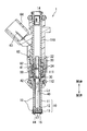
- FIG. 2 is a longitudinal sectional view showing a fuel injection valve according to an embodiment
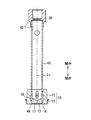
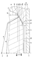
- FIG. 3 is a longitudinal sectional view showing a partially enlarged view of FIG. 4 is an enlarged longitudinal sectional view showing the contact portion of FIGS.
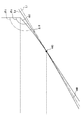
- FIG. 5 is a schematic diagram for explaining the configuration of the contact portion of FIGS.
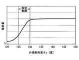
- FIG. 6 is a graph for explaining the configuration of the contact portion of FIGS.
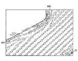
- FIG. 7 is a schematic diagram for explaining the principle of deposit adhesion to the outer circumferential convex curved surface of FIG. FIG.
- FIG. 8 is a schematic diagram for explaining the volume growth of deposits attached to the outer circumferential convex curved surface of FIG.
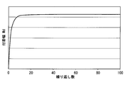
- FIG. 9 is a graph for explaining the adhesion width of the deposit that adheres to the outer circumferential convex curved surface of FIG.
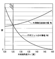
- FIG. 10 is a graph for explaining the configuration of the contact portion of FIGS.
- FIG. 11 is a graph for explaining the configuration of the contact portion of FIGS.
- FIG. 12 is a graph for explaining the correlation between the dynamic surface pressure and the wear amount;
- FIG. 13 is a longitudinal sectional view showing a modification of FIG.
- FIG. 14 is a longitudinal sectional view showing a modification of FIG.
- FIG. 15 is a longitudinal sectional view showing a modification of FIG.
- a fuel injection valve 1 is mounted on an internal combustion engine 2 that burns gasoline in a cylinder 2a.
- the fuel injection valve 1 injects the fuel sucked into the cylinder 2a together with the intake air into the intake port 2b through which the intake air flows.
- the fuel injection valve 1 includes a valve housing 10, a fixed core 20, a movable core 30, a valve member 40, an elastic member 50, and a drive unit 60.
- the valve housing 10 includes a pipe member 11, a valve seat member 12, a nozzle hole member 13, and the like.
- the cylindrical pipe member 11 has a first magnetic part 110, a nonmagnetic part 111, and a second magnetic part 112 in this order from the valve opening side to the valve closing side in the axial direction.
- the magnetic parts 110 and 112 made of a metal magnetic material and the nonmagnetic part 111 made of a metal nonmagnetic material are coupled coaxially by, for example, laser welding. Due to this coupling structure, the nonmagnetic portion 111 blocks a short circuit of magnetic flux between the first magnetic portion 110 and the second magnetic portion 112.
- the first magnetic part 110 forms a supply inlet 14 that receives the supply of fuel from the fuel pump 3 (see FIG. 1).
- a valve seat member 12 made of a cylindrical metal is coaxially fitted and fixed to the second magnetic portion 112.
- the valve seat member 12 forms a fuel passage 15 in cooperation with the pipe member 11 so that the fuel guided from the upstream side flows to the downstream side.
- the valve seat member 12 has a valve seat surface 16 exposed to the fuel passage 15 as shown in FIGS.
- the valve seat surface 16 is formed in a tapered surface shape (conical surface shape) having a constant diameter reduction rate as a reduced diameter shape that decreases in diameter toward the downstream side of the fuel passage 15.
- the nozzle member 13 made of a bottomed cylindrical metal is coaxially fitted and fixed to the valve seat member 12 on the side opposite to the second magnetic portion 112.
- the nozzle hole member 13 has a plurality of nozzle holes 17 at the bottom. Each nozzle hole 17 communicates with the fuel passage 15 on the downstream side of the valve seat surface 16 and opens radially toward the intake port 2b (see FIG. 1).
- the fixed core 20 made of a cylindrical metal magnetic body is coaxially fitted and fixed to the first magnetic part 110 and the nonmagnetic part 111.
- An adjusting pipe 22 made of a cylindrical metal is press-fitted and fixed coaxially to the fixed core 20.
- the fixed core 20 forms a fixed passage 24 together with the adjusting pipe 22 so that the fuel flowing in from the upstream supply inlet 14 flows out to the downstream side.
- the movable core 30 made of a cylindrical metal magnetic body is accommodated coaxially in the nonmagnetic portion 111 and the second magnetic portion 112.
- the movable core 30 can reciprocate to both sides in the axial direction on the valve closing side with respect to the fixed core 20.
- the valve member 40 made of a bottomed cylindrical metal nonmagnetic material is accommodated coaxially across the second magnetic portion 112 and the valve seat member 12. As shown in FIGS. 2 and 3, the valve member 40 is fitted and fixed to the movable core 30 from the valve closing side. Thereby, the valve member 40 can be reciprocated integrally with the movable core 30 to both sides in the axial direction along its own valve center line Lv.
- the valve member 40 forms a movable passage 42 together with the movable core 30 so as to guide the fuel flowing out from the upstream fixed passage 24 to the downstream fuel passage 15.
- the valve member 40 has a contact portion 44 that reciprocates on the upstream side of the valve seat surface 16 at the bottom portion on the valve closing side. As shown in FIGS. 2 to 4, the valve member 40 coaxially separates and seats the abutting portion 44 with respect to the valve seat surface 16 having the reduced diameter shape on the upstream side of all the nozzle holes 17. Specifically, the valve member 40 moves to the valve opening side, thereby causing the contact portion 44 to be separated from the valve seat surface 16 over the entire circumference. As a result, the valve member 40 is opened, and each nozzle hole 17 communicates with the fuel passage 15. Therefore, fuel is injected from each nozzle hole 17 into the intake port 2b (see FIG. 1).
- valve member 40 moves to the valve closing side to seat the contact portion 44 on the valve seat surface 16 over the entire circumference. As a result, the valve member 40 is closed and each injection hole 17 is disconnected from the fuel passage 15, so that fuel injection from each injection hole 17 is stopped. As described above, the valve member 40 can be opened and closed by opening and closing the valve seat surface 16 so that fuel injection from each nozzle hole 17 can be intermittently performed.
- the elastic member 50 is a compression coil spring made of metal, and is accommodated coaxially in the passages 24 and 42 in the fixed core 20 and the movable core 30.
- the elastic member 50 is sandwiched between the adjusting pipe 22 in the fixed core 20 and the movable core 30.
- the elastic member 50 generates an elastic restoring force in response to compression between the elements 22 and 30, thereby attaching the movable core 30 and the valve member 40 toward the valve seat surface 16 on the valve closing side. Rush. That is, the elastic restoring force generated by the elastic member 50 becomes a biasing force that biases the movable core 30 and the valve member 40.
- the driving unit 60 includes a solenoid coil 61, a spool 62, a terminal 63, a connector 64, and the like.
- the solenoid coil 61 is formed by winding a metal wire around a spool 62 made of a cylindrical resin.
- the solenoid coil 61 is coaxially fitted and fixed to the magnetic portions 110 and 112 and the nonmagnetic portion 111 via the spool 62.
- a terminal 63 made of metal is embedded in a connector 64 made of resin, and electrically connects the external control circuit 4 (see FIG. 1) and the internal solenoid coil 61. With this electrical connection, the energization of the solenoid coil 61 can be controlled by the control circuit 4.
- the solenoid coil 61 energized by the control circuit 4 is excited to excite the first magnetic part 110, the fixed core 20, the movable core 30, and the second magnetism.
- the magnetic flux is guided to the portion 112.
- a magnetic attractive force is generated between the cores 20 and 30 facing each other so as to attract the movable core 30 toward the fixed core 20 on the valve opening side.
- the movable core 30 is driven together with the valve member 40 to the valve opening side against the urging force of the elastic member 50, the movable core 30 is brought into contact with and locked to the fixed core 20.
- the valve member 40 separates the contact portion 44 from the valve seat surface 16, so that fuel is injected from each injection hole 17.
- FIG. 4 illustrates one of longitudinal sections that are cut including a valve center line Lv assumed to extend at the radial center of the valve member 40. Therefore, in the following, an arbitrary longitudinal section including the longitudinal section of FIG. 4 regarding the valve member 40 is simply referred to as a longitudinal section.
- the valve member 40 has a valve outer peripheral surface 46 that extends straight in a cylindrical shape centered on the valve center line Lv on the outer peripheral side and the valve opening side of the contact portion 44.
- the valve member 40 has a convex curved surface or a flat tip surface 47 on the inner peripheral side and the valve closing side of the contact portion 44.
- the valve member 40 has two types of convex curved surfaces 440 and 441 that are curved in a partial spherical shape, coaxially over the entire circumference of the contact portion 44.
- the inner circumferential convex surface 440 is continuous from the tip surface 47 to the outer circumferential side and the valve opening side.
- the tip surface 47 positioned downstream of the inner circumferential convex surface 440 provides a flat sac chamber 150 that guides fuel to each nozzle hole 17 when the valve is opened as part of the fuel passage 15. It is formed between the housing 10 and the nozzle hole member 13.
- the inner peripheral convex curved surface 440 has a predetermined curvature radius Ri, and has a circular arc shape in which the curvature center position Pi is defined on the longitudinal section.
- the curvature center position Pi of the inner peripheral convex curved surface 440 is defined on the valve center line Lv of the valve member 40. That is, the inner peripheral convex surface 440 is aligned with the valve outer peripheral surface 46 so as to be aligned with the valve center line Lv.
- the outer circumferential convex surface 441 is continuous from the valve outer circumferential surface 46 to the inner circumferential side and the valve closing side. As a result, the outer circumferential convex curved surface 441 forms a bent portion 442 that bends sharply from the valve outer circumferential surface 46 over the entire circumference. Moreover, the outer peripheral convex curved surface 441 is continuous from the inner peripheral convex curved surface 440 to the inner peripheral side and the valve opening side. Thereby, the outer peripheral convex curved surface 441 forms a boundary portion 443 with the inner peripheral convex convex surface 440 over the entire circumference.
- the boundary portion 443 has a shape that protrudes toward the valve seat surface 16 of the valve seat member 12 in the valve housing 10 over the entire circumference.
- the outer peripheral convex curved surface 441 has a curvature radius Ro smaller than the curvature radius Ri of the inner peripheral convex curved surface 440, and has a circular arc shape in which the curvature center position Po is defined on the vertical cross section.
- the curvature center position Po of the outer circumferential convex surface 441 is defined on the valve center line Lv on the valve closing side with respect to the curvature center position Pi of the inner circumferential convex surface 440.
- the outer peripheral convex curved surface 441 is aligned with the valve outer peripheral surface 46 so as to be aligned with the valve center line Lv.
- the protruding boundary portion 443 formed by the outer circumferential convex curved surface 441 and the inner circumferential convex curved surface 440 is also aligned with the valve outer circumferential surface 46 so as to be aligned with the valve center line Lv. Therefore, in the present embodiment, the boundary portion 443 can be separated from the tapered valve seat surface 16 having a taper angle of about 120 degrees in FIG. It has become. As a result, the alignment and stability of the boundary portion 443 seated on the tapered valve seat surface 16 is enhanced.
- a tangent that is assumed to pass through the boundary portion 443 with respect to the outer circumferential convex curved surface 441 is defined as an outer circumferential tangent Lo.
- an angle formed by the outer circumferential side tangent Lo and the valve outer circumferential surface 46 on the longitudinal section is defined as an outer circumferential side angle ⁇ o.
- the outer peripheral angle ⁇ o is in the range of 125 degrees or more and 130 degrees or less, preferably in the range of 125 degrees or more and 128 degrees or less, particularly preferably 125. It is set to about 5 degrees.
- an outer peripheral side angle ⁇ o of 125 degrees or more is employed.
- the boundary portion 443 with increased sharpness collides with the valve seat surface 16 and is easily worn as shown in FIG.
- an outer peripheral side angle ⁇ o of 130 degrees or less is employed.
- the amount of wear shown on the vertical axis in FIG. 6 is represented by the maximum depth in the axial direction of the dent caused by wear of the valve seat surface 16 by a predetermined number of valve closing operations under a constant fuel pressure.
- the adhesion width Wd from the bent portion 442 shown in FIG. 8 tends to saturate when the number of repeated valve opening operations increases to some extent. This is presumably because the accumulation of the deposit D causes the outer peripheral side angle ⁇ o in the vicinity of the bent portion 442 to be apparently increased, thereby making it difficult for the fuel flow to stay.
- the deposit width Wd of the deposit D described above is expressed in the present embodiment by the distance between the bent portion 442 and the portion Pd farthest from the bent portion 442 in the deposit D on the vertical cross section shown in FIG. Is done.
- the distance Wo between the bent portion 442 and the boundary portion 443 is determined from the adhesion width Wd of the deposit D as the width Wo of the outer circumferential convex curved surface 441 on the longitudinal section shown in FIG. Must be set larger. If the width Wo of the outer peripheral convex surface 441 is smaller than the adhesion width Wd of the deposit D, the valve closing surface in which the boundary portion 443 collides with the valve seat surface 16 between the boundary portion 443 and the valve seat surface 16. This is because the deposit D is bitten at the time of operation, leading to fuel leakage.
- the width Wo of the outer circumferential convex surface 441 and the adhesion width Wd of the deposit D are respectively the outer circumference.
- a correlation as shown in FIG. 10 appears with the side angle ⁇ o. Therefore, the setting of the outer peripheral side angle ⁇ o of 125 degrees or more based on this correlation is necessary not only from the viewpoint of static surface pressure as described above but also from the viewpoint of deposit D, in order to suppress fuel leakage. It turns out that it is a structure.
- the correlation in FIG. 10 appears when the difference in radial distance from the valve center line Lv for each of the bent portion 442 and the boundary portion 443 is secured to 0.09 mm or more.
- a tangent line that passes through the boundary portion 443 with respect to the inner peripheral convex curved surface 440 is defined as an inner peripheral tangent line Li.
- the angle formed by the inner peripheral side tangent Li and the valve outer peripheral surface 46 on the longitudinal section is defined as an inner peripheral side angle ⁇ i.
- the angle difference ⁇ between the inner peripheral angle ⁇ i and the outer peripheral angle ⁇ o is 4 degrees or more and 10 It is set within the range of degrees.
- an angle difference ⁇ of 4 degrees or more is employed.
- an angle difference ⁇ of 10 degrees or less is employed together with an outer peripheral side angle ⁇ o of 130 degrees or less.
- the fuel leakage amount shown on the vertical axis in FIG. 11 is represented by the volume of fuel that leaks within a predetermined time from between the boundary portion 443 and the valve seat surface 16 in the valve closed state, that is, the volume flow rate.
- the dynamic surface pressure realized by the present embodiment with the above configuration will be described.
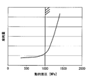
- the maximum value of the dynamic surface pressure causes a correlation as shown in FIG. 12 to appear between the amount of wear and the valve member in a state where the valve member is inclined most in the range of tolerance and is off-axis. Therefore, in the present embodiment, the dynamic surface pressure generated between the boundary portion 443 and the valve seat surface 16 during the valve closing operation in which the boundary portion 443 collides with the valve seat surface 16 is limited. That is, in the present embodiment, the outer peripheral angle ⁇ o is 130 degrees or less and the angular difference ⁇ so as to realize a dynamic surface pressure that is suppressed to 1000 MPa or less while avoiding a dynamic surface pressure exceeding 1000 MPa where the amount of wear becomes significant. Is set to 10 degrees or less.
- FIG. 12 shows the correlation between the maximum value of the dynamic surface pressure when the inclination of the valve member is 0.1 degree and the amount of wear expressed in the same manner as in FIG.
- a partial spherical surface having a radius of curvature Ro smaller than that of the inner peripheral convex surface 440 is formed on the outer peripheral side of the inner peripheral convex curved surface 440 curved in a partial spherical shape with a predetermined curvature radius Ri.
- a convex curved surface 441 on the outer peripheral side that is curved like a circle is provided continuously. As a result, the boundary 443 between the inner circumferential convex surface 440 and the outer circumferential convex surface 441 protrudes toward the valve seat surface 16, but has a shape with reduced sharpness.
- the outer peripheral side angle ⁇ o formed by the outer peripheral side tangent Lo of the outer peripheral convex surface 441 passing through the boundary portion 443 and the valve outer peripheral surface 46 is set to 125 degrees or more.
- the outer peripheral convex curved surface 441 can secure a larger gap 151 (see FIG. 4) between the boundary portion 443 and the outer peripheral side between the valve seat surface 16 whose diameter decreases toward the downstream side.
- the outer peripheral convex curved surface 441 on the outer peripheral side with respect to the boundary portion 443 is different from the valve seat surface 16. It can suppress that static surface pressure falls by contact
- a shape with reduced sharpness can be secured at the boundary portion 443 between the outer peripheral convex surface 441 and the inner peripheral convex surface 440. Therefore, between the boundary part 443 and the valve seat surface 16, the certainty of the function which suppresses the abrasion resulting from the excessive increase in dynamic surface pressure can be improved. Therefore, it is possible to contribute to suppressing fuel leakage from between the boundary portion 443 and the valve seat surface 16 in the valve closed state.
- the inner peripheral side angle ⁇ i formed by the inner peripheral side tangent Li of the inner peripheral convex surface 440 passing through the boundary portion 443 and the valve outer peripheral surface 46 is the outer peripheral side.
- the difference from the side angle ⁇ o is set to 4 degrees or more.
- the difference between the inner peripheral side angle ⁇ i and the outer peripheral side angle ⁇ o is set to 10 degrees or less on the longitudinal section of the valve member 40.
- the boundary portion 443 between the inner circumferential convex surface 440 and the outer circumferential convex surface 441 has a shape in which sharpness is reliably reduced. Therefore, between the boundary part 443 and the valve seat surface 16, the reliability of the function which suppresses the abrasion resulting from the excessive increase in dynamic surface pressure can also be improved. Therefore, it is possible to greatly contribute to suppressing fuel leakage from between the boundary portion 443 and the valve seat surface 16 in the valve closed state.
- the dynamic surface pressure generated between the boundary portion 443 and the valve seat surface 16 is suppressed to 1000 Mpa or less during the valve closing operation in which the boundary portion 443 collides with the valve seat surface 16. Become. According to this, since the function of suppressing wear can be reliably exhibited, it is possible to greatly contribute to suppressing fuel leakage from between the boundary portion 443 and the valve seat surface 16 in the valve closed state.
- the outer circumferential convex surface 441 having a small radius of curvature Ro is bent from the valve outer circumferential surface 46 on the longitudinal section of the valve member 40 by the fuel injection valve 1, the diameter thereof is reduced toward the downstream side.
- a larger gap 151 (see FIG. 4) can be secured between the valve seat surface 16 and the valve seat surface 16 toward the outer peripheral side. Therefore, even if the valve member 40 is inclined with respect to the valve seat surface 16 due to the bias of the urging force by the elastic member 50, the bent portion 442 formed by the outer peripheral convex curved surface 441 and the valve outer peripheral surface 46 is the valve seat. It is possible to prevent the static surface pressure in the closed state from being lowered by contacting the surface 16. According to this, it becomes possible to contribute to suppressing fuel leakage from between the boundary portion 443 and the valve seat surface 16 in the valve closed state.
- the boundary portion 443 A function relating to dynamic surface pressure and static surface pressure can be exerted between the valve seat surface 16 and the valve seat surface 16. Therefore, even when the fuel pressure of the injected fuel is relatively low, fuel leakage in the closed state can be suppressed.
- the outer peripheral side angle ⁇ o may be set outside the range of 125 degrees or more and 130 degrees or less as long as the effect of the present disclosure can be obtained.
- the angle difference ⁇ may be set outside the range of 4 degrees or more and 10 degrees or less as long as the operational effects of the present disclosure can be obtained.
- dynamics generated between the boundary portion 443 and the valve seat surface 16 during the valve closing operation in which the boundary portion 443 collides with the valve seat surface 16 are performed.
- the surface pressure may be set to a surface pressure exceeding 1000 MPa.
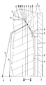
- an additional surface 444 that connects the surfaces 441 and 46 is provided on the outer peripheral side of the outer peripheral convex curved surface 441 and the inner peripheral side of the valve outer peripheral surface 46 in the contact portion 44. It may be formed. As shown in FIG. 13, the additional surface 444 is formed in a convex curved surface shape such as a partial spherical surface having a cross-sectional arc shape with a smaller radius of curvature than the outer convex curved surface 441 on the vertical cross section. Also good. Alternatively, although the additional surface 444 is not illustrated, it may be formed in a tapered surface shape, for example. In FIG. 13, a boundary portion between the outer peripheral convex curved surface 441 and the additional surface 444 is indicated by a reference numeral 445.
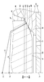
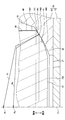
- valve seat surface 16 may be formed in a tapered surface shape with a taper angle ⁇ s other than 120 degrees. Further, as shown in FIG. 14, in the sixth modification, the valve seat surface 16 may be formed in a curved surface shape in which the diameter reduction rate that decreases toward the downstream side of the fuel passage 15 decreases toward the downstream side. Furthermore, as shown in FIG. 15, in the modified example 7, the valve seat surface 16 may be formed in a curved surface shape in which the diameter reduction rate that decreases toward the downstream side of the fuel passage 15 increases toward the downstream side. .
- the present disclosure may be applied to a fuel injection valve that injects fuel into a cylinder of a gasoline internal combustion engine.
- the present disclosure may be applied to a fuel injection valve that injects fuel into a cylinder of a diesel internal combustion engine.
Landscapes
- Engineering & Computer Science (AREA)
- Chemical & Material Sciences (AREA)
- Combustion & Propulsion (AREA)
- Mechanical Engineering (AREA)
- General Engineering & Computer Science (AREA)
- Fuel-Injection Apparatus (AREA)
Abstract
La présente invention concerne une vanne d'injection de carburant, laquelle vanne comporte : un boîtier de vanne (10) qui a un trou d'injection (17) à travers lequel du carburant est injecté dans un moteur à combustion interne et une surface de siège de vanne (16) dont le diamètre est réduit vers un côté aval, d'un côté amont du trou d'injection (17) ; un élément de vanne (40) qui est reçu dans le boîtier de vanne (10) et qui est séparé de la surface de siège de vanne (16) et logé sur cette dernière de manière coaxiale pour effectuer l'ouverture et la fermeture de vanne, de façon à provoquer ainsi une injection par intermittence de carburant à partir du trou d'injection (17) ; et un élément élastique qui sollicite l'élément de vanne (40) vers la surface de siège de vanne (16). L'élément de vanne (40) a une surface incurvée convexe de côté périphérique interne (440) qui est partiellement incurvée selon un rayon de courbure prédéterminé (Ri) et une surface incurvée convexe de côté périphérique externe (441) qui est située sur un côté périphérique externe de la surface incurvée convexe de côté périphérique interne (440) de manière continue à partir de cette dernière et qui est partiellement incurvée de manière sphérique selon un plus petit rayon de courbure (Ro) que la surface incurvée convexe de côté périphérique interne (440). Une partie de limite (443) entre la surface incurvée convexe de côté périphérique interne (440) et la surface incurvée convexe de côté périphérique externe (441) fait saillie vers la surface de siège de vanne (16) de manière à permettre une séparation et une réception.
Priority Applications (3)
| Application Number | Priority Date | Filing Date | Title |
|---|---|---|---|
| DE112016003154.8T DE112016003154T5 (de) | 2015-07-14 | 2016-05-25 | Kraftstoffeinspritzventil |
| US15/742,066 US10648440B2 (en) | 2015-07-14 | 2016-05-25 | Fuel injection valve |
| CN201680041141.5A CN107835897B (zh) | 2015-07-14 | 2016-05-25 | 燃料喷射阀 |
Applications Claiming Priority (4)
| Application Number | Priority Date | Filing Date | Title |
|---|---|---|---|
| JP2015140771 | 2015-07-14 | ||
| JP2015-140771 | 2015-07-14 | ||
| JP2016-037257 | 2016-02-29 | ||
| JP2016037257A JP6256495B2 (ja) | 2015-07-14 | 2016-02-29 | 燃料噴射弁 |
Publications (1)
| Publication Number | Publication Date |
|---|---|
| WO2017010034A1 true WO2017010034A1 (fr) | 2017-01-19 |
Family
ID=57757165
Family Applications (1)
| Application Number | Title | Priority Date | Filing Date |
|---|---|---|---|
| PCT/JP2016/002528 Ceased WO2017010034A1 (fr) | 2015-07-14 | 2016-05-25 | Vanne d'injection de carburant |
Country Status (1)
| Country | Link |
|---|---|
| WO (1) | WO2017010034A1 (fr) |
Cited By (1)
| Publication number | Priority date | Publication date | Assignee | Title |
|---|---|---|---|---|
| CN113294274A (zh) * | 2020-02-06 | 2021-08-24 | 株式会社京浜 | 电磁式燃料喷射阀 |
Citations (4)
| Publication number | Priority date | Publication date | Assignee | Title |
|---|---|---|---|---|
| JPS5970079U (ja) * | 1982-11-01 | 1984-05-12 | 愛三工業株式会社 | 電磁燃料噴射器 |
| JP2002500308A (ja) * | 1997-12-23 | 2002-01-08 | シーメンス オートモーティヴ コーポレイション | 加圧渦流型燃料噴射器の平頭ニードル |
| JP2003003934A (ja) * | 2001-06-20 | 2003-01-08 | Denso Corp | 燃料噴射弁 |
| JP2009150358A (ja) * | 2007-12-21 | 2009-07-09 | Denso Corp | 燃料噴射弁 |
-
2016
- 2016-05-25 WO PCT/JP2016/002528 patent/WO2017010034A1/fr not_active Ceased
Patent Citations (4)
| Publication number | Priority date | Publication date | Assignee | Title |
|---|---|---|---|---|
| JPS5970079U (ja) * | 1982-11-01 | 1984-05-12 | 愛三工業株式会社 | 電磁燃料噴射器 |
| JP2002500308A (ja) * | 1997-12-23 | 2002-01-08 | シーメンス オートモーティヴ コーポレイション | 加圧渦流型燃料噴射器の平頭ニードル |
| JP2003003934A (ja) * | 2001-06-20 | 2003-01-08 | Denso Corp | 燃料噴射弁 |
| JP2009150358A (ja) * | 2007-12-21 | 2009-07-09 | Denso Corp | 燃料噴射弁 |
Cited By (1)
| Publication number | Priority date | Publication date | Assignee | Title |
|---|---|---|---|---|
| CN113294274A (zh) * | 2020-02-06 | 2021-08-24 | 株式会社京浜 | 电磁式燃料喷射阀 |
Similar Documents
| Publication | Publication Date | Title |
|---|---|---|
| US9297471B2 (en) | Solenoid valve | |
| JP5623784B2 (ja) | 電磁式燃料噴射弁 | |
| US9303608B2 (en) | Fuel injector | |
| CN102369350B (zh) | 燃料喷射阀 | |
| US20120204839A1 (en) | Electromagnetic fuel injection valve | |
| JP5262972B2 (ja) | 燃料噴射弁 | |
| JP2010014088A (ja) | 電磁式燃料噴射弁 | |
| JP2010014088A5 (fr) | ||
| JP6205482B2 (ja) | 電磁式弁 | |
| CN104912709B (zh) | 燃料喷射阀 | |
| JP6256495B2 (ja) | 燃料噴射弁 | |
| JP4782804B2 (ja) | 燃料噴射弁 | |
| JP2015025406A (ja) | 燃料噴射弁 | |
| JP6354519B2 (ja) | 燃料噴射弁 | |
| US20060208108A1 (en) | Fuel injection valve | |
| JP3932967B2 (ja) | 燃料噴射装置 | |
| JP6554955B2 (ja) | 燃料噴射弁 | |
| US20200102922A1 (en) | Fuel injection valve | |
| JP6658019B2 (ja) | 燃料噴射弁 | |
| JP2011127486A (ja) | 燃料噴射弁 | |
| JP4305858B2 (ja) | 燃料噴射弁 | |
| CN118510987A (zh) | 电磁式燃料喷射阀 | |
| WO2023233661A1 (fr) | Soupape d'injection de combustible gazeux | |
| JP2006242148A (ja) | 燃料噴射弁 | |
| JP2013139824A (ja) | 燃料噴射弁 |
Legal Events
| Date | Code | Title | Description |
|---|---|---|---|
| 121 | Ep: the epo has been informed by wipo that ep was designated in this application |
Ref document number: 16824020 Country of ref document: EP Kind code of ref document: A1 |
|
| WWE | Wipo information: entry into national phase |
Ref document number: 112016003154 Country of ref document: DE |
|
| 122 | Ep: pct application non-entry in european phase |
Ref document number: 16824020 Country of ref document: EP Kind code of ref document: A1 |