WO2017010169A1 - 乗員保護装置 - Google Patents
乗員保護装置 Download PDFInfo
- Publication number
- WO2017010169A1 WO2017010169A1 PCT/JP2016/065105 JP2016065105W WO2017010169A1 WO 2017010169 A1 WO2017010169 A1 WO 2017010169A1 JP 2016065105 W JP2016065105 W JP 2016065105W WO 2017010169 A1 WO2017010169 A1 WO 2017010169A1
- Authority
- WO
- WIPO (PCT)
- Prior art keywords
- chamber
- sub
- vehicle
- protection device
- seat
- Prior art date
- Legal status (The legal status is an assumption and is not a legal conclusion. Google has not performed a legal analysis and makes no representation as to the accuracy of the status listed.)
- Ceased
Links
Images


Classifications
-
- B—PERFORMING OPERATIONS; TRANSPORTING
- B60—VEHICLES IN GENERAL
- B60R—VEHICLES, VEHICLE FITTINGS, OR VEHICLE PARTS, NOT OTHERWISE PROVIDED FOR
- B60R21/00—Arrangements or fittings on vehicles for protecting or preventing injuries to occupants or pedestrians in case of accidents or other traffic risks
- B60R21/02—Occupant safety arrangements or fittings, e.g. crash pads
- B60R21/16—Inflatable occupant restraints or confinements designed to inflate upon impact or impending impact, e.g. air bags
- B60R21/20—Arrangements for storing inflatable members in their non-use or deflated condition; Arrangement or mounting of air bag modules or components
- B60R21/207—Arrangements for storing inflatable members in their non-use or deflated condition; Arrangement or mounting of air bag modules or components in vehicle seats
-
- A—HUMAN NECESSITIES
- A47—FURNITURE; DOMESTIC ARTICLES OR APPLIANCES; COFFEE MILLS; SPICE MILLS; SUCTION CLEANERS IN GENERAL
- A47C—CHAIRS; SOFAS; BEDS
- A47C31/00—Details or accessories for chairs, beds, or the like, not provided for in other groups of this subclass, e.g. upholstery fasteners, mattress protectors, stretching devices for mattress nets
- A47C31/02—Upholstery attaching means
-
- B—PERFORMING OPERATIONS; TRANSPORTING
- B60—VEHICLES IN GENERAL
- B60N—SEATS SPECIALLY ADAPTED FOR VEHICLES; VEHICLE PASSENGER ACCOMMODATION NOT OTHERWISE PROVIDED FOR
- B60N2/00—Seats specially adapted for vehicles; Arrangement or mounting of seats in vehicles
- B60N2/24—Seats specially adapted for vehicles; Arrangement or mounting of seats in vehicles for particular purposes or particular vehicles
- B60N2/42—Seats specially adapted for vehicles; Arrangement or mounting of seats in vehicles for particular purposes or particular vehicles the seat constructed to protect the occupant from the effect of abnormal g-forces, e.g. crash or safety seats
- B60N2/427—Seats or parts thereof displaced during a crash
-
- B—PERFORMING OPERATIONS; TRANSPORTING
- B60—VEHICLES IN GENERAL
- B60N—SEATS SPECIALLY ADAPTED FOR VEHICLES; VEHICLE PASSENGER ACCOMMODATION NOT OTHERWISE PROVIDED FOR
- B60N2/00—Seats specially adapted for vehicles; Arrangement or mounting of seats in vehicles
- B60N2/58—Seat coverings
-
- B—PERFORMING OPERATIONS; TRANSPORTING
- B60—VEHICLES IN GENERAL
- B60R—VEHICLES, VEHICLE FITTINGS, OR VEHICLE PARTS, NOT OTHERWISE PROVIDED FOR
- B60R21/00—Arrangements or fittings on vehicles for protecting or preventing injuries to occupants or pedestrians in case of accidents or other traffic risks
- B60R21/02—Occupant safety arrangements or fittings, e.g. crash pads
- B60R21/16—Inflatable occupant restraints or confinements designed to inflate upon impact or impending impact, e.g. air bags
- B60R21/23—Inflatable members
- B60R21/231—Inflatable members characterised by their shape, construction or spatial configuration
- B60R21/23138—Inflatable members characterised by their shape, construction or spatial configuration specially adapted for side protection
-
- B—PERFORMING OPERATIONS; TRANSPORTING
- B60—VEHICLES IN GENERAL
- B60R—VEHICLES, VEHICLE FITTINGS, OR VEHICLE PARTS, NOT OTHERWISE PROVIDED FOR
- B60R21/00—Arrangements or fittings on vehicles for protecting or preventing injuries to occupants or pedestrians in case of accidents or other traffic risks
- B60R21/02—Occupant safety arrangements or fittings, e.g. crash pads
- B60R21/16—Inflatable occupant restraints or confinements designed to inflate upon impact or impending impact, e.g. air bags
- B60R21/23—Inflatable members
- B60R21/231—Inflatable members characterised by their shape, construction or spatial configuration
- B60R21/233—Inflatable members characterised by their shape, construction or spatial configuration comprising a plurality of individual compartments; comprising two or more bag-like members, one within the other
-
- B—PERFORMING OPERATIONS; TRANSPORTING
- B60—VEHICLES IN GENERAL
- B60R—VEHICLES, VEHICLE FITTINGS, OR VEHICLE PARTS, NOT OTHERWISE PROVIDED FOR
- B60R21/00—Arrangements or fittings on vehicles for protecting or preventing injuries to occupants or pedestrians in case of accidents or other traffic risks
- B60R21/02—Occupant safety arrangements or fittings, e.g. crash pads
- B60R21/16—Inflatable occupant restraints or confinements designed to inflate upon impact or impending impact, e.g. air bags
- B60R21/23—Inflatable members
- B60R21/239—Inflatable members characterised by their venting means
-
- B—PERFORMING OPERATIONS; TRANSPORTING
- B60—VEHICLES IN GENERAL
- B60R—VEHICLES, VEHICLE FITTINGS, OR VEHICLE PARTS, NOT OTHERWISE PROVIDED FOR
- B60R21/00—Arrangements or fittings on vehicles for protecting or preventing injuries to occupants or pedestrians in case of accidents or other traffic risks
- B60R21/02—Occupant safety arrangements or fittings, e.g. crash pads
- B60R21/16—Inflatable occupant restraints or confinements designed to inflate upon impact or impending impact, e.g. air bags
- B60R21/26—Inflatable occupant restraints or confinements designed to inflate upon impact or impending impact, e.g. air bags characterised by the inflation fluid source or means to control inflation fluid flow
- B60R21/268—Inflatable occupant restraints or confinements designed to inflate upon impact or impending impact, e.g. air bags characterised by the inflation fluid source or means to control inflation fluid flow using instantaneous release of stored pressurised gas
-
- B—PERFORMING OPERATIONS; TRANSPORTING
- B60—VEHICLES IN GENERAL
- B60N—SEATS SPECIALLY ADAPTED FOR VEHICLES; VEHICLE PASSENGER ACCOMMODATION NOT OTHERWISE PROVIDED FOR
- B60N2/00—Seats specially adapted for vehicles; Arrangement or mounting of seats in vehicles
- B60N2/58—Seat coverings
- B60N2002/5808—Seat coverings comprising opening zones for airbags
-
- B—PERFORMING OPERATIONS; TRANSPORTING
- B60—VEHICLES IN GENERAL
- B60R—VEHICLES, VEHICLE FITTINGS, OR VEHICLE PARTS, NOT OTHERWISE PROVIDED FOR
- B60R21/00—Arrangements or fittings on vehicles for protecting or preventing injuries to occupants or pedestrians in case of accidents or other traffic risks
- B60R21/02—Occupant safety arrangements or fittings, e.g. crash pads
- B60R21/16—Inflatable occupant restraints or confinements designed to inflate upon impact or impending impact, e.g. air bags
- B60R21/20—Arrangements for storing inflatable members in their non-use or deflated condition; Arrangement or mounting of air bag modules or components
- B60R21/207—Arrangements for storing inflatable members in their non-use or deflated condition; Arrangement or mounting of air bag modules or components in vehicle seats
- B60R2021/2076—Removable covers with tear seams
-
- B—PERFORMING OPERATIONS; TRANSPORTING
- B60—VEHICLES IN GENERAL
- B60R—VEHICLES, VEHICLE FITTINGS, OR VEHICLE PARTS, NOT OTHERWISE PROVIDED FOR
- B60R21/00—Arrangements or fittings on vehicles for protecting or preventing injuries to occupants or pedestrians in case of accidents or other traffic risks
- B60R21/02—Occupant safety arrangements or fittings, e.g. crash pads
- B60R21/16—Inflatable occupant restraints or confinements designed to inflate upon impact or impending impact, e.g. air bags
- B60R21/23—Inflatable members
- B60R21/231—Inflatable members characterised by their shape, construction or spatial configuration
- B60R21/23138—Inflatable members characterised by their shape, construction or spatial configuration specially adapted for side protection
- B60R2021/23146—Inflatable members characterised by their shape, construction or spatial configuration specially adapted for side protection seat mounted
-
- B—PERFORMING OPERATIONS; TRANSPORTING
- B60—VEHICLES IN GENERAL
- B60R—VEHICLES, VEHICLE FITTINGS, OR VEHICLE PARTS, NOT OTHERWISE PROVIDED FOR
- B60R21/00—Arrangements or fittings on vehicles for protecting or preventing injuries to occupants or pedestrians in case of accidents or other traffic risks
- B60R21/02—Occupant safety arrangements or fittings, e.g. crash pads
- B60R21/16—Inflatable occupant restraints or confinements designed to inflate upon impact or impending impact, e.g. air bags
- B60R21/23—Inflatable members
- B60R21/231—Inflatable members characterised by their shape, construction or spatial configuration
- B60R21/233—Inflatable members characterised by their shape, construction or spatial configuration comprising a plurality of individual compartments; comprising two or more bag-like members, one within the other
- B60R2021/23324—Inner walls crating separate compartments, e.g. communicating with vents
- B60R2021/23332—Inner walls crating separate compartments, e.g. communicating with vents using independent bags, one within the other
Definitions
- the present invention relates to an occupant protection device provided with a side airbag device.
- the side airbag device described in Patent Document 1 below includes a main airbag and an auxiliary airbag. And an occupant is restrained at an early stage by inflating and deploying the auxiliary airbag prior to the main airbag.
- a side airbag device including an auxiliary airbag in addition to the main airbag has been proposed. In such a side airbag device, there is a strong demand for a compact device. Furthermore, not only the main airbag but also the occupant harm by the auxiliary airbag is required to be suppressed.
- the present invention has been made in view of the above situation, and provides a side airbag device capable of restraining an occupant quickly and appropriately at an early stage of airbag deployment, and an occupant protection device including the side airbag device. With the goal.
- Another object of the present invention is to provide a side airbag device that contributes to downsizing of the device and an occupant protection device including the side airbag device.
- the present invention solves the above problems in an occupant protection device including a vehicle seat having a seat cushion that forms a seat surface and a seat back that forms a backrest, and a side airbag device that is accommodated in the seat. It is.
- the seat back includes a side support portion that bulges in the vehicle traveling direction (front of the vehicle) at the side portion (end portion) in the vehicle width direction.
- a seat frame forming a frame of the seat is provided inside the vehicle seat.
- the side airbag device includes an airbag that restrains an occupant by being inflated and deployed; and an inflator that supplies inflation gas to the airbag.
- a side frame portion that is a part of the seat frame is disposed inside the side support portion, and the side airbag device is accommodated on the outer side in the vehicle width direction of the side frame portion.
- the airbag includes a main chamber that is deployed toward the front of the side support portion; and a sub chamber that is deployed toward the front from between the main chamber and the side support portion.
- the sub-chamber expands forward from the vehicle front edge portion of the side frame, and projects and deforms at least a front portion of the side support portion toward the occupant side.
- the sub-chamber expands only inside the side support part.
- the main chamber expands toward the front outside of the side support portion.
- the present invention configured as described above, it is possible to quickly restrain the occupant from moving outward in the vehicle width direction by deploying the sub-chamber inside the side support portion at the initial stage of operation of the airbag device. It becomes. At this time, the sub-chamber expands further forward than the vehicle front edge portion of the side frame, and at least the front portion of the side support portion protrudes and deforms toward the occupant side, so that the occupant is pressed toward the inner side in the vehicle width direction. It looks like this. As a result, the generation of force that pushes the occupant diagonally forward from the back direction can be avoided or minimized, and the occupant can be prevented from moving in the direction of pulling out the seat belt.
- the side support portion it is sufficient if there is a sub-chamber that develops only inside the side support, so that more gas generated can be directed to the main chamber.
- the main chamber is set to expand toward the front outside of the side support portion, the expansion of the main chamber due to the expansion of the sub chamber is less likely to be hindered, so that the expansion is smooth and the cooperation with the sub chamber. This improves passenger protection performance.
- the inflator can be housed in the sub-chamber.
- the main chamber and the sub-chamber are divided and provided, the internal space of the main chamber and the internal space of the sub-chamber are connected by a vent hole, and the expansion gas inside the sub-chamber is supplied to the vent. It is preferable to flow to the main chamber through a hole.
- the main chamber and the sub chamber are divided and provided, an intermediate chamber is connected between the main chamber and the sub chamber, the inflator is accommodated in the intermediate chamber, and the main chamber and the intermediate chamber are separated from each other.
- a first vent hole is formed at the boundary
- a second vent hole is formed at the boundary between the sub-chamber and the intermediate chamber, and the expansion gas in the intermediate chamber passes through the first and second vent holes.
- And can be configured to be distributed to the sub-chamber and the main chamber.
- the second vent hole larger than the first vent hole, the development of the sub-chamber can be accelerated.
- the sub-chamber By disposing the sub-chamber on the occupant side with respect to the main chamber, it is possible to avoid the inconvenience that the sub-chamber wraps around the occupant's buttocks (back side) at the initial stage of deployment.
- a starting point region that is a starting point when the side support portion bends toward the occupant side due to the expansion of the sub chamber is formed in the side support portion.
- the side support portion is easily bent by the force developed by the sub-chamber of the airbag, and it is possible to reliably restrain the occupant from moving outward in the vehicle width direction immediately after the occurrence of the collision accident.
- region it can be set as either a notch
- the sub-chamber is disposed below the side support portion so that the lumbar portion of the occupant is pushed from the side by the side support portion by the development of the sub-chamber.
- a webbing covering at least a part of the main chamber and the sub-chamber can be further provided. And it is preferable that the said cloth has a weak part used as the starting point which cleaves when the said sub chamber expand
- the main chamber can be smoothly deployed by cleaving the baffle with the sub-chamber that develops only inside the side support and has a relatively small capacity and a short deployment time. That is, the main chamber expands at once from the cleaved portion of the webbing and can be quickly deployed outside the side support.
- the webbing can be composed of a first webbing located on the vehicle outer side of the side airbag and a second webbing located on the vehicle inner side of the side airbag.
- bonds the vehicle rear part of the said 1st force cloth and the vehicle rear part of the said 2nd force cloth can be provided.
- the baffle itself helps to tear the seat (side support part) skin when the airbag is deployed, and the wire enhances the effect.
- the tension applied to the webbing during deployment of the airbag can be increased by the wire, and the tearing of the seat skin can be completed at an earlier timing during deployment. Thereby, the movement timing of the occupant in the lateral direction by the sub-chamber can be advanced, and the occupant restraining effect when the main chamber is fully deployed can be further enhanced.
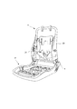
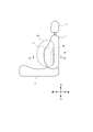
- FIG. 1 is a perspective view mainly showing an outer appearance shape of a vehicle seat used in an occupant protection device according to a first embodiment of the present invention, and illustration of an airbag unit is omitted.
- FIG. 2 is a perspective view showing an internal structure (seat frame) that functions as a framework of the vehicle seat shown in FIG. 1, and illustration of the airbag unit is omitted.
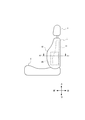
- FIG. 3 is a schematic side view of the occupant protection device according to the first embodiment, and shows a state in which the state in which the airbag unit is accommodated is observed from the outside in the vehicle width direction.
- FIG. 4 is a cross-sectional view showing a part of a cross section in the A1-A1 direction of FIG. FIG.
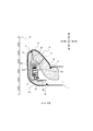
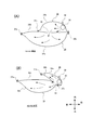
- FIG. 5 is a schematic side view of the occupant protection device according to the first embodiment, and shows a state where the airbag is observed from the outside in the vehicle width direction.
- FIG. 6 is a schematic view showing a deployed state of the airbag corresponding to the cross section in the A2-A2 direction of FIG. 5, and (A) and (B) show different aspects.
- FIGS. 7A and 7B are explanatory views showing the deployed state of the airbag apparatus according to the first embodiment, where FIG. 7A shows the initial stage of deployment and FIG. 7B shows the late stage of deployment.
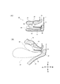
- FIG. 8 is a sectional view showing an occupant protection device according to the second embodiment of the present invention, which coincides with the direction of FIG. For convenience of explanation, illustration of the inside of the airbag unit is omitted.
- FIG. 8 is a sectional view showing an occupant protection device according to the second embodiment of the present invention, which coincides with the direction of FIG. For convenience of explanation, illustration of the inside of the airbag unit is omitted.
- FIG. 9 is a cross-sectional view showing a modification of the embodiment of FIG.
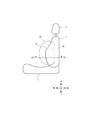
- FIG. 10 is a schematic side view of the occupant protection device according to the third embodiment of the present invention, and shows a state where the airbag is observed from the outside in the vehicle width direction.
- FIG. 11 is a schematic view showing a deployed state of the airbag corresponding to the cross section in the A3-A3 direction of FIG.
- a vehicle seat equipped with a side airbag device will be described with reference to the accompanying drawings. Note that “front” displayed in each figure is the front of the vehicle (traveling direction), “rear” is the rear of the vehicle (opposite to the traveling direction), and “inside” is the inner side of the vehicle width (occupant side) “Outside” indicates the vehicle width direction outside (door panel side).
- FIG. 1 is a perspective view mainly showing an outer appearance shape of a vehicle seat used in an occupant protection device according to a first embodiment of the present invention, and illustration of an airbag device (20) is omitted.
- FIG. 2 is a perspective view showing an internal structure (seat frame) that functions as a framework of the vehicle seat shown in FIG. 1, and illustration of the airbag device (20) is omitted.
- FIG. 3 is a schematic side view of the occupant protection device according to the first embodiment, and the state in which the airbag device 20 is accommodated on the side surface (near side) close to the door of the vehicle seat is observed from the outside in the vehicle width direction. Show the state.
- FIG. 1 is a perspective view mainly showing an outer appearance shape of a vehicle seat used in an occupant protection device according to a first embodiment of the present invention, and illustration of an airbag device (20) is omitted.
- FIG. 2 is a perspective view showing an internal structure (seat frame) that functions as a framework of the vehicle seat shown in FIG
- FIG. 4 is a cross-sectional view showing a part of a cross section in the A1-A1 direction of FIG.
- FIG. 5 is a schematic side view of the occupant protection device according to the first embodiment, and shows a state where the airbag is observed from the outside in the vehicle width direction.
- FIG. 6 is a schematic view showing a deployed state of the airbag corresponding to the cross section in the A2-A2 direction of FIG. 5, and (A) and (B) show different aspects.
- FIGS. 7A and 7B are explanatory views showing the deployed state of the airbag apparatus according to the first embodiment, where FIG. 7A shows the initial stage of deployment and FIG. 7B shows the late stage of deployment.
- the present invention is an occupant protection device including a vehicle seat and a side airbag device (20) accommodated in the seat.
- a vehicle seat according to the present embodiment is viewed as a part, as shown in FIGS. 1 and 2, a seat cushion 2 at a portion where an occupant sits; a seat back 1 that forms a backrest; and an upper end of the seat back 1 And a headrest 3 connected to the headrest 3.
- a seat back frame 1 f that forms a skeleton of the seat is provided inside the seat back 1, and a pad made of urethane foam or the like is provided on the surface and the periphery of the seat back frame 1.
- the surface of the pad is a skin 14 such as leather or fabric. Covered by.
- a seating frame 2f is disposed on the bottom side of the seat cushion 2, and a pad made of urethane foam or the like is provided on the upper surface and the periphery thereof, and the surface of the pad is covered with a skin 14 such as leather or fabric.
- the seating frame 2 f and the seat back frame 1 f are connected via a reclining mechanism 4.
- the seat back frame 1 f connects the side frame 10 that is spaced apart from the left and right and extends in the vertical direction, the upper frame that connects the upper end of the side frame 10, and the lower end. It is comprised by frame shape with the lower frame.
- the headrest 3 is configured by providing a cushion member on the outside of the headrest frame.
- the side frame 10 is formed of resin or metal, and can have an L-shaped cross section or a U-shaped cross section as shown in FIG. As will be described later, an airbag module (side airbag device) 20 is fixed to the side frame 10.
- the seat back 1 includes a side support portion 12 that bulges in the vehicle traveling direction (front of the vehicle) at the vehicle width direction side portion (end portion).
- the side airbag device 20 is accommodated in a gap where the urethane pad 16 is not disposed.
- the side airbag device 20 includes an airbag (34, 36) that restrains an occupant by inflating and deploying; and an inflator 30 that supplies inflation gas to the airbag (34, 36).
- the airbags (34, 36) and the inflator (30) are disposed on the outer side of the side frame portion 10 in the vehicle width direction.
- the airbags (34, 36) are covered with a flexible cover 20a made of fabric.
- the airbag (34, 36) is folded or rolled in a bellows shape (including “rolling”), and an optimal compression method is appropriately adopted.
- symbol 25 shows a door trim.
- the sub-chamber and the main chamber are overlapped in a flat and flat state so as to maintain the positional relationship during inflation and deployment.
- the folded sub-chamber portion is disposed closer to the inflator than the folded main chamber portion, or the folded main chamber portion And the side frame. That is, the folded sub-chamber may be disposed on the passenger side with respect to the folded main chamber.
- the joints 18, 22, and 24 of the skin 14 of the seat back 1 are woven inside and connected by sewing.
- the front seam 18 is torn when the airbag is deployed.
- the side support portion 12 is formed with a starting point region 26 that becomes a starting point when the side support portion 12 bends toward the occupant side due to the expansion of the sub-chamber 36 (see FIGS. 5 and 6).
- the starting region 26 can be any one or combination of a cut, a concave portion, and a thin region.
- the starting point region 26 may be formed only in the urethane 16 portion inside the side support portion 12.
- the airbag (34, 36) has a main chamber 34 that is deployed toward the front of the side support portion 12; and is deployed forward from between the main chamber 34 and the side support portion 12.
- a sub-chamber 36 As shown in FIG. 4, the sub-chamber 36 is deployed forward from the vehicle front edge portion 10 a of the side frame portion 10, so that at least the front portion 14 of the side support portion 12 projects and deforms toward the occupant side. It has become. Further, the sub-chamber 36 is disposed below the side support portion 12 (see FIG. 5), and the side support portion 12 comes into contact with and presses the occupant's waist by the development of the sub-chamber 36.
- the capacity of the sub chamber 36 is set smaller than the capacity of the main chamber 34.
- the shape and capacity of the sub-chamber may be adjusted so that the sub-chamber is deployed only inside the side support portion 12. In other words, the developed sub-chamber may not protrude beyond the front end of the cleaved side support part. As a result, the sub-chamber can be fully expanded earlier than the main chamber, while the main chamber can be filled with more gas. You may set the main chamber 34 so that it may expand
- This setting is possible depending on how the airbag is folded, the arrangement of the folded airbag, the setting of the gas injection direction of the inflator, the direction of gas flow between the sub chamber and the main chamber, and the like.
- the development of the main chamber due to the development of the sub-chamber is less hindered, and the development of the main chamber becomes smooth.
- the occupant protection performance is improved by cooperating with the development of the sub chamber along with the development of the main chamber.
- the inflator 30 is accommodated in the sub chamber 36.
- a cylindrical cylinder type inflator can be used.
- a pair of upper and lower stud bolts 32 protrude from the outer periphery of the inflator 30 toward the inner side in the vehicle width direction. These stud bolts 32 are attached to the side frame 10 by nuts (fastened and fixed).
- the inflator 30 is formed with a plurality of gas jets arranged in the circumferential direction, and gas is jetted radially from the gas jets.
- a diffuser for controlling the gas flow can be provided as necessary.
- the inflator 30 is electrically connected to an airbag control ECU mounted on the vehicle.
- a satellite sensor for detecting a side collision is electrically connected to the airbag control ECU.
- the inflator 30 can be configured to operate when the airbag control ECU detects a side collision based on the signal from the satellite sensor.
- a vent hole 38 communicating with the main chamber 34 and the sub chamber 36 is formed in the inner panel 34b of the main chamber 34 so that the expansion gas inside the sub chamber 36 flows into the main chamber 34 through the vent hole 38. It has become. With such a structure, since the sub-chamber 36 is deployed prior to the deployment of the main chamber 34, it is possible to quickly restrain the movement of the occupant in the lateral direction.
- the bag-shaped main chamber 34 is formed by sewing (37a, 37b) the peripheral edges of the outer panel 34a and the inner panel 34b.
- a bag-like subchamber 36 is formed by sewing (37d, 37b) the peripheral edges of the outer panel 36b and the inner panel 36b.
- the front edges of the panels 34a and 34b of the main chamber 34 are connected by sewing.
- the front edges of the panels 36a and 36b of the sub-chamber 36 are connected by sewing.
- Vent holes 39 communicating with these chambers (34, 36) are formed in the inner panel 34b of the main chamber 34 and the outer panel 36b of the sub chamber 36, and the expansion gas inside the sub chamber 36 is vent holes 39. Through the main chamber 34. The periphery of the vent hole 39 is sewn at a sewing location 37b.
- the sub-chamber 36 is deployed inside the side support portion 12 in the initial stage of the operation of the airbag device 20, and the seat While the outer skin 14 is cleaved from the sewing portion 18, the front end side of the side support portion 12 is deformed so as to bend or protrude toward the inside of the vehicle starting from the region 26, and the occupant is restrained so as to push inward in the vehicle width direction. Note that the expansion of the main chamber 34 is not completed when the expansion of the sub-chamber 36 is completed.
- the sub-chamber 36 expands forward from the vehicle front edge portion 10a of the side frame 10, and the front side portion of the side support portion 12 projects and deforms toward the occupant side, so that the occupant is pushed obliquely forward from the back direction. Generation of force can be avoided or minimized, and movement of the occupant in the direction of pulling out the seat belt can be avoided. That is, it is possible to suppress the damaging effect on the passenger and maximize the restraint performance.
- FIG. 8 is a cross-sectional view showing an occupant protection device according to the second embodiment of the present invention, which coincides with the direction of FIG. For convenience of explanation, illustration of the inside of the airbag device 20 is omitted.
- FIG. 9 is a cross-sectional view showing a modification of the embodiment of FIG.
- a webbing (40a, 40b) that covers at least a part of the main chamber 34 and the sub-chamber 36 is further provided.
- the force cloth (40a, 40b) efficiently conveys the energy that the airbag inflates and deploys to the urethane structure of the seat, accelerates the tearing of the seat itself, improves the deployment speed of the bag, and improves the passenger protection performance.
- the first force cloth 40a located on the vehicle outer side of the side airbag and the second force cloth 40b located on the vehicle inner side are configured.
- the front end portion of the bundling (40a, 40b) is coupled to the seat seam 18 in the front portion of the seat back, and the rear end portion of the bundling (40a, 40b) is connected to the rear portion of the airbag of the seat frame 10. Combined.
- the bundlings 40a and 40b have a fragile portion that becomes a starting point for cleavage when the sub-chamber 36 is deployed.
- the fragile portion is usually provided in the vicinity of the cleavage portion of the seat, but it is preferable that the fragile portion is provided in a place where the remaining blanket does not get in the way when the main bag inflates and expands and jumps out to the front of the vehicle.
- the sub-chamber 36 preferably has a relatively small capacity that develops only inside the side support 12 and has a short development time. For this reason, smooth deployment of the main chamber 34 can be promoted by applying the bundlings 40 a and 40 b along with the development of the sub-chamber 36.
- the inflated and deployed energy of the airbag is efficiently transmitted to the urethane portion in the seat, and the seat is quickly cleaved, so that the main chamber 34 is inflated at once from the cleaved portion. It protrudes and can be quickly deployed outside the side support portion 12.
- the second webbing 40 b may be made short and the rear part thereof may be connected by the wire 42.
- the vehicle rear portion of the first baffle 40a and the vehicle rear portion of the wire 42 coupled to the vehicle rear portion of the second force cloth 40b may be coupled to the airbag rear portion of the seat frame 10.
- a reinforcing portion (overlapping the cloth) that can hold the wire is provided at the ends of the force cloths 40a and 40b, and the wire 42 is fixed with a stapler or the like.
- a wire-like ring metal fitting may be provided at the end of the bundlings 40a and 40b, and the wire 42 may be passed therethrough.
- One or a plurality of wires 42 are provided, and in the case of a plurality of wires 42, they may be either parallel or non-parallel, and may be mesh-like depending on the case.
- the bundlings 40a and 40b themselves assist the tearing of the skin 14 of the side support portion 12 when the airbag (34, 36) is deployed, and the wire 42 enhances the effect. Since the wire 42 hardly stretches, the tension applied to the webbings 40a and 40b when the airbag is deployed can be increased by the wire 42, and the tearing of the seat skin 14 can be completed at an earlier timing during deployment. Thereby, the movement timing of the occupant in the lateral direction by the sub-chamber 36 can be advanced, and the occupant restraining effect when the main chamber 34 is fully deployed can be further enhanced.
- the portion where the wire is provided may be provided on the first force cloth, or may be provided on both the first force cloth and the second force cloth.
- the shape of the bundling itself is preferably a wide band shape, but if economically allowed, it can be formed to cover as large a wide area as possible. It is preferable that the bundling is provided at a position including the center portion with respect to the vertical direction of the airbag during storage.
- FIG. 10 is a schematic side view of an occupant protection device according to a third embodiment of the present invention, showing a state in which the airbag is observed from the outside in the vehicle width direction.
- FIG. 11 is a schematic view showing a deployed state of the airbag corresponding to the cross section in the A3-A3 direction of FIG.
- an intermediate chamber 44 is connected between the main chamber 34 and the sub chamber 36, and the inflator 30 is accommodated in the intermediate chamber 44.
- the intermediate panel 60 is disposed so as to wrap the inflator 30, and the main chamber 34 is formed by the outer surface of the intermediate panel 60 and the outer panel 34 a.
- the sub-chamber 36 is formed by the inner surface of the intermediate panel 60 and the inner panel 36a.
- a first vent hole 52 a is formed at the boundary between the main chamber 34 and the intermediate chamber 44
- a second vent hole 52 b is formed at the boundary between the sub chamber 36 and the intermediate chamber 44.
- the expansion gas in the intermediate chamber 44 is configured to be distributed to the main chamber 34 and the sub chamber 36 via the first and second vent holes 52a and 52b.
- the second vent hole 52b By making the second vent hole 52b larger than the first vent hole 52a, the sub-chamber 36 can be deployed more quickly.
- the first vent hole 52a and the second vent hole 52b have the same size, the sub chamber 36 has a smaller volume, so that it is fully expanded earlier than the main chamber 34. Therefore, it is also possible to set the optimum expansion / deployment timing of the main chamber and the sub chamber by adjusting the size, shape, position, etc. of the vent hole in accordance with the characteristics of the vehicle and the seat.
- the intermediate chamber 44 is provided, and different vent holes 52a and 52b are formed in the main chamber 34 and the sub-chamber 36, so that the development timing of the main chamber 34 and the sub-chamber 36 can be controlled easily and closely. It becomes.
- the near-side side airbag has been described mainly.
- the far-side airbag surface far from the vehicle door of the vehicle seat
- the small vehicle such as small mobility, etc. It can also be used for a single-seat vehicle (a vehicle including a portion having only one seat in a row regardless of whether there is a door) or the like.
Landscapes
- Engineering & Computer Science (AREA)
- Mechanical Engineering (AREA)
- Physics & Mathematics (AREA)
- Fluid Mechanics (AREA)
- Aviation & Aerospace Engineering (AREA)
- Transportation (AREA)
- Air Bags (AREA)
Abstract
Description
また、装置のコンパクト化に寄与するサイドエアバッグ装置及びこれを備えた乗員保護装置を提供することを他の目的とする。
また、サブチャンバをメインチャンバの展開に先行して展開させることにより、速やかに乗員の横方向の移動を拘束することが可能となる。
力布自体はエアバッグの展開時にシート(サイドサポート部)表皮の開裂を助けるものであり、ワイヤはその効果を高めるものである。エアバッグ展開時に力布に加わる張力をワイヤによって大きくすることができ、展開時により早いタイミングでシート表皮の開裂を完了することができる。これによって、サブチャンバによる乗員の横方向への移動タイミングを早くすることができ、メインチャンバのフル展開時の乗員拘束効果をより高めることができる。
Claims (17)
- 座面を形成するシートクッションと背もたれを形成するシートバックとを有する車両シートと、当該シートに収容されるサイドエアバッグ装置とを備えた乗員保護装置において、
前記シートバックは、車幅方向側部(端部)において車両進行方向(車両前方)に膨出したサイドサポート部を備え、
前記車両シートの内部にはシートの骨格を形成するシートフレームが設けられ、
前記サイドエアバッグ装置は、膨張展開することで乗員を拘束するエアバッグと;前記エアバッグに対して膨張ガスを供給するインフレータとを備え、
前記サイドサポート部の内部には、前記シートフレームの一部であるサイドフレーム部が配置され、当該サイドフレーム部の車幅方向外側に前記サイドエアバッグ装置が収容され、
前記エアバッグは、前記サイドサポート部の前方に向かって展開するメインチャンバと;前記メインチャンバと前記サイドサポート部の間から前方に向かって展開するサブチャンバとを備え、
前記サブチャンバは、前記サイドフレームの車両前方縁部よりも前方に向かって展開し、前記サイドサポート部の少なくとも前側部分を乗員側に向かって突出変形させることを特徴とする乗員保護装置。 - 前記サブチャンバは、前記サイドサポート部の内部でのみ展開することを特徴とする請求項1に記載の乗員保護装置。
- 前記メインチャンバは、前記サイドサポート部の前方外側に向かって展開することを特徴とする請求項1又は2に記載の乗員保護装置。
- 前記インフレータは、前記サブチャンバ内に収容されることを特徴とする請求項1乃至3の何れか一項に記載の乗員保護装置。
- 前記メインチャンバと前記サブチャンバとは区画されて設けられており、ベントホールによって前記メインチャンバの内部空間と前記サブチャンバの内部空間とが連結され、前記サブチャンバ内部の膨張ガスが前記ベントホールを介して前記メインチャンバに流れることを特徴とする請求項4に記載の乗員保護装置。
- 前記メインチャンバと前記サブチャンバとは区画されて設けられており、前記メインチャンバと前記サブチャンバとの間に、中間チャンバが連結され、
前記インフレータは前記中間チャンバ内に収容され、
前記メインチャンバと前記中間チャンバとの境界には第1のベントホールが形成されて前記メインチャンバの内部空間と前記中間チャンバの内部空間とが連結され、前記サブチャンバと前記中間チャンバとの境界には第2のベントホールが形成され前記サブチャンバの内部空間と前記中間チャンバの内部空間とが連結され、
前記中間チャンバ内の膨張ガスが前記第1及び第2のベントホールを介して前記サブチャンバと前記メインチャンバとに分配されることを特徴とする請求項1乃至3の何れか一項に記載の乗員保護装置。 - 前記第2のベントホールが前記第1のベントホールより大きいことを特徴とする請求項6に記載の乗員保護装置。
- 前記サブチャンバは、前記メインチャンバの展開に先行して展開することを特徴とする請求項1乃至7の何れか一項に記載の乗員保護装置。
- 前記サブチャンバは前記メインチャンバに対して乗員側に配置されることを特徴とする請求項1乃至8の何れか一項に記載の乗員保護装置。
- 前記サブチャンバの膨張によって前記サイドサポート部が乗員側に折れ曲がる際の起点となる起点領域が前記サイドサポート部に形成されていることを特徴とする請求項1乃至9の何れか一項に記載の乗員保護装置。
- 前記起点領域は、切り込み、凹部又は薄肉領域の何れか又は組み合わせであることを特徴とする請求項10に記載の乗員保護装置。
- 前記サブチャンバの展開により、前記サイドサポート部によって乗員の腰部が押されるように、前記サブチャンバが前記サイドサポート部の下方に配置されていることを特徴とする請求項1乃至11の何れか一項に記載の乗員保護装置。
- 前記メインチャンバ及び前記サブチャンバの少なくとも一部を覆う力布を更に備えたことを特徴とする請求項1乃至12の何れか一項に記載の乗員保護装置。
- 前記力布は、前記サブチャンバが展開した時に開裂する起点となる脆弱部を有することを特徴とする請求項13に記載の乗員保護装置。
- 前記力布は、前記サイドエアバッグの車両外側に位置する第1力布と前記サイドエアバッグの車両内側に位置する第2力布とを含むことを特徴とする請求項13又は14に記載の乗員保護装置。
- 前記第1力布の車両後方部分と前記第2力布の車両後方部分とを結合するワイヤを備えたことを特徴とする請求項15に記載の乗員保護装置。
- 請求項1乃至16の何れか一項に記載の乗員保護装置に装備されるサイドエアバッグ装置。
Priority Applications (5)
| Application Number | Priority Date | Filing Date | Title |
|---|---|---|---|
| EP16824149.5A EP3321138B1 (en) | 2015-07-11 | 2016-05-20 | Vehicle occupant protection device |
| CN201680040335.3A CN107848483B (zh) | 2015-07-11 | 2016-05-20 | 驾乘人员保护装置 |
| US15/740,436 US10464517B2 (en) | 2015-07-11 | 2016-05-20 | Vehicle occupant protection device |
| KR1020177034764A KR102004535B1 (ko) | 2015-07-11 | 2016-05-20 | 승차인 보호 장치 |
| JP2017528317A JP6435412B2 (ja) | 2015-07-11 | 2016-05-20 | 乗員保護装置 |
Applications Claiming Priority (2)
| Application Number | Priority Date | Filing Date | Title |
|---|---|---|---|
| JP2015-139273 | 2015-07-11 | ||
| JP2015139273 | 2015-07-11 |
Publications (1)
| Publication Number | Publication Date |
|---|---|
| WO2017010169A1 true WO2017010169A1 (ja) | 2017-01-19 |
Family
ID=57756928
Family Applications (1)
| Application Number | Title | Priority Date | Filing Date |
|---|---|---|---|
| PCT/JP2016/065105 Ceased WO2017010169A1 (ja) | 2015-07-11 | 2016-05-20 | 乗員保護装置 |
Country Status (6)
| Country | Link |
|---|---|
| US (1) | US10464517B2 (ja) |
| EP (1) | EP3321138B1 (ja) |
| JP (1) | JP6435412B2 (ja) |
| KR (1) | KR102004535B1 (ja) |
| CN (1) | CN107848483B (ja) |
| WO (1) | WO2017010169A1 (ja) |
Cited By (10)
| Publication number | Priority date | Publication date | Assignee | Title |
|---|---|---|---|---|
| JP2018176906A (ja) * | 2017-04-07 | 2018-11-15 | トヨタ自動車株式会社 | 車両用サイドエアバッグ装置及びその製造方法 |
| JP2019055660A (ja) * | 2017-09-20 | 2019-04-11 | トヨタ自動車株式会社 | サイドエアバッグ装置を搭載した車両用シート及びサイドエアバッグ装置 |
| EP3511210A1 (en) * | 2018-01-15 | 2019-07-17 | Autoliv Development AB | Side airbag device and vehicle seat having the side airbag device |
| WO2019146382A1 (ja) * | 2018-01-26 | 2019-08-01 | オートリブ ディベロップメント エービー | サイドエアバッグ装置及び、これを備えた車両用シート |
| WO2019193984A1 (ja) * | 2018-04-05 | 2019-10-10 | オートリブ ディベロップメント エービー | サイドエアバッグ装置及び、これを備えた車両用シート |
| WO2020071099A1 (ja) * | 2018-10-03 | 2020-04-09 | オートリブ ディベロップメント エービー | 車両用シート |
| CN111615473A (zh) * | 2018-01-11 | 2020-09-01 | 奥托立夫开发公司 | 乘员保护装置 |
| WO2020241020A1 (ja) * | 2019-05-31 | 2020-12-03 | オートリブ ディベロップメント エービー | サイドエアバッグ装置及び、サイドエアバッグ装置の製造方法 |
| JPWO2021070526A1 (ja) * | 2019-10-10 | 2021-04-15 | ||
| WO2022009757A1 (ja) * | 2020-07-09 | 2022-01-13 | オートリブ ディベロップメント エービー | エアバッグ装置 |
Families Citing this family (10)
| Publication number | Priority date | Publication date | Assignee | Title |
|---|---|---|---|---|
| KR102095578B1 (ko) * | 2016-06-01 | 2020-03-31 | 오토리브 디벨로프먼트 에이비 | 승차인 보호 장치 |
| JP6394657B2 (ja) * | 2016-07-22 | 2018-09-26 | トヨタ自動車株式会社 | 車両用乗員拘束装置 |
| JP6848762B2 (ja) * | 2017-08-09 | 2021-03-24 | トヨタ自動車株式会社 | サイドエアバッグ装置 |
| EP3517371B1 (en) * | 2018-01-26 | 2021-11-03 | Autoliv Development AB | Side airbag device |
| DE102018202417A1 (de) * | 2018-02-16 | 2019-08-22 | Takata AG | Fahrzeuginsassen-Rückhaltesystem |
| KR102535016B1 (ko) * | 2018-06-19 | 2023-05-23 | 아우토리브 디벨롭먼트 아베 | 사이드 에어백 장치 및 이것을 구비한 차량용 시트 |
| CN113423617B (zh) * | 2018-12-21 | 2023-05-02 | 奥托立夫开发公司 | 侧面安全气囊装置及其制造方法、具备该装置的车辆座椅 |
| WO2020162065A1 (ja) * | 2019-02-09 | 2020-08-13 | オートリブ ディベロップメント エービー | サイドエアバッグ装置 |
| JP7564735B2 (ja) * | 2021-03-02 | 2024-10-09 | 本田技研工業株式会社 | サイドエアバッグ装置 |
| JP7564734B2 (ja) * | 2021-03-02 | 2024-10-09 | 本田技研工業株式会社 | サイドエアバッグ装置 |
Citations (2)
| Publication number | Priority date | Publication date | Assignee | Title |
|---|---|---|---|---|
| JP2013199152A (ja) * | 2012-03-23 | 2013-10-03 | Ts Tech Co Ltd | シートフレーム |
| JP2014080169A (ja) * | 2012-10-18 | 2014-05-08 | Toyota Motor Corp | サイドエアバッグ装置を搭載した車両用シート |
Family Cites Families (19)
| Publication number | Priority date | Publication date | Assignee | Title |
|---|---|---|---|---|
| US6578911B2 (en) * | 2000-11-30 | 2003-06-17 | Ts Tech Co., Ltd. | Seat provided with air bag module |
| GB2397048A (en) * | 2003-01-10 | 2004-07-14 | Autoliv Dev | Vehicle seat comprising airbag |
| GB2408023A (en) * | 2003-11-11 | 2005-05-18 | Autoliv Dev | Side air bag with internal tether |
| ATE543693T1 (de) * | 2007-03-15 | 2012-02-15 | Takata Petri Ag | Fahrzeugsitzanordnung und verfahren zum schützen eines fahrzeuginsassen |
| JP4952422B2 (ja) | 2007-07-19 | 2012-06-13 | 豊田合成株式会社 | サイドエアバッグ装置 |
| US8613465B2 (en) * | 2008-12-29 | 2013-12-24 | Honda Motor Co., Ltd. | Side airbag device |
| DE102009021635B4 (de) * | 2009-05-16 | 2014-06-26 | Autoliv Development Ab | Seitengassack-Einheit, Fahrzeugsitz und Kraftfahrzeug |
| KR101283698B1 (ko) * | 2011-03-29 | 2013-07-05 | 기아자동차주식회사 | 차량의 사이드 에어백 |
| JP5626470B2 (ja) * | 2011-07-28 | 2014-11-19 | トヨタ自動車株式会社 | サイドエアバッグ装置を備えた車両用シート |
| US9592789B2 (en) * | 2012-07-25 | 2017-03-14 | Toyota Jidosha Kabushiki Kaisha | Side airbag deployment direction control structure |
| CN107719291B (zh) * | 2012-12-28 | 2020-11-20 | 提爱思科技股份有限公司 | 安全气囊模块装备座椅及其装配方法 |
| JP5696748B2 (ja) * | 2013-07-31 | 2015-04-08 | トヨタ自動車株式会社 | 車両用サイドエアバッグ装置及び車両用シート |
| US8905431B1 (en) * | 2013-09-24 | 2014-12-09 | Ford Global Technologies, Llc | Side airbag assembly for a vehicle seat |
| TWI548548B (zh) * | 2014-01-16 | 2016-09-11 | 提愛思科技股份有限公司 | 安裝構件及裝備氣囊模組之座椅 |
| JP6323438B2 (ja) * | 2015-12-16 | 2018-05-16 | トヨタ自動車株式会社 | サイドエアバッグ装置を搭載した車両用シート |
| JP6394657B2 (ja) * | 2016-07-22 | 2018-09-26 | トヨタ自動車株式会社 | 車両用乗員拘束装置 |
| JP6561942B2 (ja) * | 2016-08-22 | 2019-08-21 | トヨタ自動車株式会社 | サイドエアバッグ装置を搭載した車両用シート |
| JP6848762B2 (ja) * | 2017-08-09 | 2021-03-24 | トヨタ自動車株式会社 | サイドエアバッグ装置 |
| JP6856482B2 (ja) * | 2017-09-20 | 2021-04-07 | トヨタ自動車株式会社 | サイドエアバッグ装置を搭載した車両用シート及びサイドエアバッグ装置 |
-
2016
- 2016-05-20 CN CN201680040335.3A patent/CN107848483B/zh active Active
- 2016-05-20 WO PCT/JP2016/065105 patent/WO2017010169A1/ja not_active Ceased
- 2016-05-20 KR KR1020177034764A patent/KR102004535B1/ko active Active
- 2016-05-20 EP EP16824149.5A patent/EP3321138B1/en active Active
- 2016-05-20 US US15/740,436 patent/US10464517B2/en active Active
- 2016-05-20 JP JP2017528317A patent/JP6435412B2/ja active Active
Patent Citations (2)
| Publication number | Priority date | Publication date | Assignee | Title |
|---|---|---|---|---|
| JP2013199152A (ja) * | 2012-03-23 | 2013-10-03 | Ts Tech Co Ltd | シートフレーム |
| JP2014080169A (ja) * | 2012-10-18 | 2014-05-08 | Toyota Motor Corp | サイドエアバッグ装置を搭載した車両用シート |
Cited By (29)
| Publication number | Priority date | Publication date | Assignee | Title |
|---|---|---|---|---|
| JP2018176906A (ja) * | 2017-04-07 | 2018-11-15 | トヨタ自動車株式会社 | 車両用サイドエアバッグ装置及びその製造方法 |
| JP2019055660A (ja) * | 2017-09-20 | 2019-04-11 | トヨタ自動車株式会社 | サイドエアバッグ装置を搭載した車両用シート及びサイドエアバッグ装置 |
| US11077815B2 (en) | 2017-09-20 | 2021-08-03 | Toyota Jidosha Kabushiki Kaisha | Vehicle seat equipped with side airbag device, and side airbag device |
| EP3738840A4 (en) * | 2018-01-11 | 2021-06-16 | Autoliv Development AB | OCCUPANT PROTECTION DEVICE |
| EP3960553A1 (en) * | 2018-01-11 | 2022-03-02 | Autoliv Development AB | Occupant protection apparatus |
| CN111615473A (zh) * | 2018-01-11 | 2020-09-01 | 奥托立夫开发公司 | 乘员保护装置 |
| EP3511210A1 (en) * | 2018-01-15 | 2019-07-17 | Autoliv Development AB | Side airbag device and vehicle seat having the side airbag device |
| WO2019146382A1 (ja) * | 2018-01-26 | 2019-08-01 | オートリブ ディベロップメント エービー | サイドエアバッグ装置及び、これを備えた車両用シート |
| US11254276B2 (en) | 2018-01-26 | 2022-02-22 | Autoliv Development Ab | Side airbag apparatus and vehicle seat including the same |
| JPWO2019146382A1 (ja) * | 2018-01-26 | 2020-11-26 | オートリブ ディベロップメント エービー | サイドエアバッグ装置及び、これを備えた車両用シート |
| CN111918795A (zh) * | 2018-04-05 | 2020-11-10 | 奥托立夫开发公司 | 侧面安全气囊装置以及具有该装置的车辆用座椅 |
| US11351948B2 (en) | 2018-04-05 | 2022-06-07 | Autoliv Development Ab | Side airbag device and vehicle seat provided with same |
| WO2019193984A1 (ja) * | 2018-04-05 | 2019-10-10 | オートリブ ディベロップメント エービー | サイドエアバッグ装置及び、これを備えた車両用シート |
| JPWO2019193984A1 (ja) * | 2018-04-05 | 2021-02-12 | オートリブ ディベロップメント エービー | サイドエアバッグ装置及び、これを備えた車両用シート |
| WO2020071099A1 (ja) * | 2018-10-03 | 2020-04-09 | オートリブ ディベロップメント エービー | 車両用シート |
| US11358555B2 (en) | 2018-10-03 | 2022-06-14 | Autoliv Development Ab | Vehicle seat |
| WO2020241020A1 (ja) * | 2019-05-31 | 2020-12-03 | オートリブ ディベロップメント エービー | サイドエアバッグ装置及び、サイドエアバッグ装置の製造方法 |
| JPWO2020241020A1 (ja) * | 2019-05-31 | 2020-12-03 | ||
| US11752965B2 (en) | 2019-05-31 | 2023-09-12 | Autoliv Development Ab | Side airbag device and method for manufacturing side airbag device |
| JP7449930B2 (ja) | 2019-05-31 | 2024-03-14 | オートリブ ディベロップメント エービー | サイドエアバッグ装置及び、サイドエアバッグ装置の製造方法 |
| CN114401868A (zh) * | 2019-10-10 | 2022-04-26 | 奥托立夫开发公司 | 侧面安全气囊装置及其配备的安全气囊的制造方法 |
| WO2021070526A1 (ja) * | 2019-10-10 | 2021-04-15 | オートリブ ディベロップメント エービー | サイドエアバッグ装置及び、これに用いられるエアバッグの製造方法 |
| JPWO2021070526A1 (ja) * | 2019-10-10 | 2021-04-15 | ||
| JP7277067B2 (ja) | 2019-10-10 | 2023-05-18 | オートリブ ディベロップメント エービー | サイドエアバッグ装置及び、これに用いられるエアバッグの製造方法 |
| CN114401868B (zh) * | 2019-10-10 | 2023-11-07 | 奥托立夫开发公司 | 侧面安全气囊装置及其配备的安全气囊的制造方法 |
| US12030453B2 (en) | 2019-10-10 | 2024-07-09 | Autoliv Development Ab | Side airbag device and method for manufacturing airbag used in same |
| JPWO2022009757A1 (ja) * | 2020-07-09 | 2022-01-13 | ||
| WO2022009757A1 (ja) * | 2020-07-09 | 2022-01-13 | オートリブ ディベロップメント エービー | エアバッグ装置 |
| JP7514307B2 (ja) | 2020-07-09 | 2024-07-10 | オートリブ ディベロップメント エービー | エアバッグ装置 |
Also Published As
| Publication number | Publication date |
|---|---|
| EP3321138B1 (en) | 2021-10-13 |
| CN107848483B (zh) | 2019-12-20 |
| US20180186326A1 (en) | 2018-07-05 |
| KR20180002763A (ko) | 2018-01-08 |
| US10464517B2 (en) | 2019-11-05 |
| EP3321138A4 (en) | 2019-01-16 |
| JPWO2017010169A1 (ja) | 2018-03-01 |
| CN107848483A (zh) | 2018-03-27 |
| KR102004535B1 (ko) | 2019-10-01 |
| EP3321138A1 (en) | 2018-05-16 |
| JP6435412B2 (ja) | 2018-12-05 |
Similar Documents
| Publication | Publication Date | Title |
|---|---|---|
| JP6435412B2 (ja) | 乗員保護装置 | |
| JP6646146B2 (ja) | 乗員保護装置 | |
| JP6183342B2 (ja) | 車両用乗員保護装置 | |
| JP6414157B2 (ja) | 車両用乗員拘束装置 | |
| JP6748294B2 (ja) | 乗員保護装置 | |
| JP7449930B2 (ja) | サイドエアバッグ装置及び、サイドエアバッグ装置の製造方法 | |
| JP6940627B2 (ja) | 乗員保護装置 | |
| CN110077353A (zh) | 侧气囊装置 | |
| JPWO2019026538A1 (ja) | 乗員保護装置 | |
| JP6982562B2 (ja) | サイドエアバッグ装置 | |
| US11358555B2 (en) | Vehicle seat | |
| WO2019146382A1 (ja) | サイドエアバッグ装置及び、これを備えた車両用シート | |
| JP6790024B2 (ja) | サイドエアバッグ装置及び、これを備えた車両用シート | |
| JP2018127110A (ja) | サイドエアバッグ装置を搭載した車両用シート | |
| JP6865723B2 (ja) | 車両用シート | |
| JP7554345B2 (ja) | サイドエアバッグ装置、及びその製造方法 | |
| JP6551330B2 (ja) | 車両用乗員拘束装置 | |
| JP2017206205A (ja) | 乗員保護装置 |
Legal Events
| Date | Code | Title | Description |
|---|---|---|---|
| 121 | Ep: the epo has been informed by wipo that ep was designated in this application |
Ref document number: 16824149 Country of ref document: EP Kind code of ref document: A1 |
|
| ENP | Entry into the national phase |
Ref document number: 2017528317 Country of ref document: JP Kind code of ref document: A |
|
| ENP | Entry into the national phase |
Ref document number: 20177034764 Country of ref document: KR Kind code of ref document: A |
|
| NENP | Non-entry into the national phase |
Ref country code: DE |
|
| WWE | Wipo information: entry into national phase |
Ref document number: 2016824149 Country of ref document: EP |