WO2017010175A1 - Écrou de boîtier - Google Patents
Écrou de boîtier Download PDFInfo
- Publication number
- WO2017010175A1 WO2017010175A1 PCT/JP2016/065556 JP2016065556W WO2017010175A1 WO 2017010175 A1 WO2017010175 A1 WO 2017010175A1 JP 2016065556 W JP2016065556 W JP 2016065556W WO 2017010175 A1 WO2017010175 A1 WO 2017010175A1
- Authority
- WO
- WIPO (PCT)
- Prior art keywords
- nut
- case
- main body
- insulating member
- electrodeposition coating
- Prior art date
- Legal status (The legal status is an assumption and is not a legal conclusion. Google has not performed a legal analysis and makes no representation as to the accuracy of the status listed.)
- Ceased
Links
Images



Classifications
-
- F—MECHANICAL ENGINEERING; LIGHTING; HEATING; WEAPONS; BLASTING
- F16—ENGINEERING ELEMENTS AND UNITS; GENERAL MEASURES FOR PRODUCING AND MAINTAINING EFFECTIVE FUNCTIONING OF MACHINES OR INSTALLATIONS; THERMAL INSULATION IN GENERAL
- F16B—DEVICES FOR FASTENING OR SECURING CONSTRUCTIONAL ELEMENTS OR MACHINE PARTS TOGETHER, e.g. NAILS, BOLTS, CIRCLIPS, CLAMPS, CLIPS OR WEDGES; JOINTS OR JOINTING
- F16B37/00—Nuts or like thread-engaging members
- F16B37/04—Devices for fastening nuts to surfaces, e.g. sheets, plates
- F16B37/044—Nut cages
-
- F—MECHANICAL ENGINEERING; LIGHTING; HEATING; WEAPONS; BLASTING
- F16—ENGINEERING ELEMENTS AND UNITS; GENERAL MEASURES FOR PRODUCING AND MAINTAINING EFFECTIVE FUNCTIONING OF MACHINES OR INSTALLATIONS; THERMAL INSULATION IN GENERAL
- F16B—DEVICES FOR FASTENING OR SECURING CONSTRUCTIONAL ELEMENTS OR MACHINE PARTS TOGETHER, e.g. NAILS, BOLTS, CIRCLIPS, CLAMPS, CLIPS OR WEDGES; JOINTS OR JOINTING
- F16B37/00—Nuts or like thread-engaging members
- F16B37/04—Devices for fastening nuts to surfaces, e.g. sheets, plates
- F16B37/06—Devices for fastening nuts to surfaces, e.g. sheets, plates by means of welding or riveting
- F16B37/061—Devices for fastening nuts to surfaces, e.g. sheets, plates by means of welding or riveting by means of welding
Definitions
- the present invention relates to a case nut in which a nut is freely housed inside a case main body welded to the body of an automobile.
- a case nut is used as a nut provided on the body side (Patent Document 1).
- the case nut is a case in which a nut is slidably housed inside a case body welded to the body.
- the electrodeposition coating process is a coating process for forming a coating film on the surface of the body by immersing the body in an electrolyte and energizing it. For this reason, when an electrodeposition coating process is applied to a body provided with a conventional case nut, the metal nut accommodated freely can be energized by contacting the inner wall of the case body or the body. As a result, the electrodeposition paint is also deposited on the nut. Accordingly, there is a problem that the nut is firmly fixed to the inner wall surface or the body of the case main body and does not move freely.
- An object of the present invention is to solve the above-mentioned conventional problems and to provide a case nut in which a nut housed in a swingable manner inside a case main body is not fixed by an electrodeposition coating process.
- the present invention made to solve the above-mentioned problems is a case nut comprising a case main body welded to the body, and a nut freely housed inside the case main body, wherein the nut is a metal
- a nut body made of resin and a resin insulating member formed on the outer periphery of the nut body, the upper surface, the lower surface, and the outer periphery of the nut body being in non-contact with the inner wall surface of the case body and the body. It is characterized by.
- the insulating member has a convex portion that contacts the inner wall surface and the body of the case main body, and the convex portion is a side portion of the nut main body. It is located in.
- the invention according to claim 3 is the case nut according to claim 2, wherein a notch is formed at a corner of the case body.
- the case nut according to the present invention is formed of a metal nut main body and an outer periphery of the nut main body, and the upper surface, the lower surface, and the outer peripheral surface of the nut main body are made of a resin that is not in contact with the inner wall surface of the case main body and the body.
- a nut composed of an insulating member is slidably accommodated inside the case body.
- the body is subjected to high temperature drying treatment.
- the insulating member is formed with a convex portion that contacts the inner wall surface of the case main body and the body, and the convex portion is positioned on a side portion of the nut main body. Due to this convex portion, the contact area between the insulating member and the inner wall surface of the case main body and the body is reduced, so that it is possible to avoid the strong sticking of the nut caused by the remaining electrolyte being dried at a high temperature. That is, by applying vibration or the like after drying at a high temperature, the nut can be easily separated from the inner wall surface or the body of the case main body and can be freely moved inside the case main body.
- the case nut of the present invention is composed of a case main body and a nut that is slidably accommodated inside the case main body.
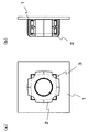
- a metal case main body 2 having a substantially U-shaped vertical section to be welded and a nut 3 movably housed inside the case main body 2 are provided.
- the body 1 is subjected to an electrodeposition coating treatment as a base treatment for enhancing the corrosion resistance.
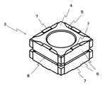
- the nut 3 includes a metal nut body 4 and a resin insulating member 6 formed on the upper surface, the lower surface, and the outer peripheral surface of the nut body 4.
- the insulating member 6 is insert-molded in a recess 5 in which the outer peripheral surface of the nut body 4 is recessed in the axial direction.
- the insulating member 6 is formed so as to slightly protrude outward from the upper surface, the lower surface, and the outer peripheral surface of the nut body 4. That is, when the nut 3 is housed in the case main body 2, each surface of the nut main body 4 has a structure that is not in contact with the inner wall surface of the case main body 2 and the body 1 due to the presence of the insulating member 6. Therefore, the metal nut body 4 can be insulated by contacting the insulating member 6 with the inner wall surface of the case body 2 and the body 1 instead of the nut body 4 during the electrodeposition coating process.
- the insulating member 6 formed on the upper surface side and the lower surface side of the nut body 4 is formed with a convex portion 7 that contacts the inner wall surface of the case body 2 and the body 1.
- this convex part 7 is located in the side part of the nut main body 4, and it is more preferable that it is formed in the approximate center of the side part of the nut main body 4.
- the body 1 is subjected to a high temperature drying process. Therefore, by forming the convex portion 7 described above, the contact area between the insulating member 6 and the inner wall surface of the case body 2 and the body 1 is reduced. Therefore, the nut 3 caused by the remaining electrolyte being dried at a high temperature. Can be avoided.
- the insulating member 6 is made of nylon 6 (registered trademark). This is because nylon 6 has a high melting point of 260 ° C. and can withstand the high temperatures caused by the electrodeposition coating process.
- the material of the insulating member 6 is alkali resistant and may be any material that can withstand the electrodeposition coating process at 180 ° C. (that is, preferably a material having a melting point of 240 ° C. or higher), and is made of, for example, polyphenylene sulfide. You can also.
- the insulating member 6 formed on the outer peripheral surface of the nut body 4 may be provided with a groove 8 formed by cutting in the horizontal direction. Thereby, the flow path of the electrolyte solution at the time of the electrodeposition coating process can be secured, and the liquid pool can be prevented.
- a notch 9 is formed at the corner of the case body 2.
- a bolt hole 11 through which the bolt 10 passes is formed on the upper surface of the case body 2.
- the usage method of the case nut of this invention comprised in this way is demonstrated below.
- a high temperature drying process is further performed.
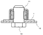
- the nut body 4 can be insulated by the insulating member 6 described above, and the electrodeposition coating process can be performed. Since the portion 7 can prevent the nut 3 from being firmly fixed due to high-temperature drying, the nut 3 can be easily separated from the inner wall surface of the case body 2 and the body 1 by vibration or the like after both treatments, and can be moved freely inside the case body 2. It becomes. Therefore, as shown in FIG. 5, the bolt 3 is screwed into the nut 3 with the attached part 12 attached to the body 1 in contact with the nut 3. Therefore, the accessory part 12 can be easily fixed to the body 1.
- (Second Embodiment) 6 and 7 show a second embodiment.
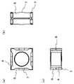
- an insulating member 6 made of resin is insert-molded at the outer edge of the nut body 4, and the substantially spherical convex portion 7 that contacts the inner wall surface of the case body 2 and the body 1 is formed as a side portion of the nut body 4. Is formed at a substantially central position.
- the metal nut main body 4 can be insulated at the time of an electrodeposition coating process, and the adhesion to the inner wall part of the case main body 2 and the body 1 can be prevented. It becomes.
- the convex part 7 is formed smaller than the first embodiment, the contact area between the insulating member 6 and the inner wall surface of the case main body 2 and the body 1 becomes smaller, and the high temperature drying process is performed. The sticking can be further reduced.
Landscapes
- Engineering & Computer Science (AREA)
- General Engineering & Computer Science (AREA)
- Mechanical Engineering (AREA)
- Preventing Corrosion Or Incrustation Of Metals (AREA)
- Bolts, Nuts, And Washers (AREA)
- Application Of Or Painting With Fluid Materials (AREA)
- Connection Of Plates (AREA)
- Vehicle Body Suspensions (AREA)
Abstract
L'invention concerne un écrou de boîtier, lequel écrou, qui est maintenu à l'intérieur d'un corps de boîtier de manière à osciller librement, n'est pas fixe dû à un traitement de revêtement par électrodéposition. L'écrou de boîtier comporte un corps de boîtier (2) qui est soudé à un corps (1), et un écrou (3) qui est maintenu à l'intérieur dudit corps de boîtier (2) de manière à flotter librement. L'écrou (3) comporte un corps d'écrou métallique (4) et un élément isolant en résine (6) qui est formé sur l'extérieur dudit corps d'écrou (4) et qui empêche tout contact de la surface supérieure, de la surface inférieure et des surfaces externes du corps d'écrou (4) avec les surfaces de paroi internes du corps de boîtier (2) et avec le corps (1).
Priority Applications (3)
| Application Number | Priority Date | Filing Date | Title |
|---|---|---|---|
| CN201680032445.5A CN107735584B (zh) | 2015-07-13 | 2016-05-26 | 卡式螺母 |
| EP16824155.2A EP3324058B1 (fr) | 2015-07-13 | 2016-05-26 | Écrou de boîtier |
| US15/825,482 US10156250B2 (en) | 2015-07-13 | 2017-11-29 | Case nut |
Applications Claiming Priority (2)
| Application Number | Priority Date | Filing Date | Title |
|---|---|---|---|
| JP2015-139830 | 2015-07-13 | ||
| JP2015139830A JP6529367B2 (ja) | 2015-07-13 | 2015-07-13 | ケースナット |
Related Child Applications (1)
| Application Number | Title | Priority Date | Filing Date |
|---|---|---|---|
| US15/825,482 Continuation US10156250B2 (en) | 2015-07-13 | 2017-11-29 | Case nut |
Publications (1)
| Publication Number | Publication Date |
|---|---|
| WO2017010175A1 true WO2017010175A1 (fr) | 2017-01-19 |
Family
ID=57756948
Family Applications (1)
| Application Number | Title | Priority Date | Filing Date |
|---|---|---|---|
| PCT/JP2016/065556 Ceased WO2017010175A1 (fr) | 2015-07-13 | 2016-05-26 | Écrou de boîtier |
Country Status (5)
| Country | Link |
|---|---|
| US (1) | US10156250B2 (fr) |
| EP (1) | EP3324058B1 (fr) |
| JP (1) | JP6529367B2 (fr) |
| CN (1) | CN107735584B (fr) |
| WO (1) | WO2017010175A1 (fr) |
Families Citing this family (4)
| Publication number | Priority date | Publication date | Assignee | Title |
|---|---|---|---|---|
| JP6016981B1 (ja) * | 2015-05-19 | 2016-10-26 | 株式会社青山製作所 | ケースナット |
| JP6504957B2 (ja) * | 2015-07-27 | 2019-04-24 | 株式会社青山製作所 | ケースナット |
| TWI737525B (zh) * | 2020-10-28 | 2021-08-21 | 緯創資通股份有限公司 | 螺母構件與包含其之電子裝置 |
| DE102022104013A1 (de) | 2022-02-21 | 2023-08-24 | Audi Aktiengesellschaft | Käfigmutter |
Citations (7)
| Publication number | Priority date | Publication date | Assignee | Title |
|---|---|---|---|---|
| JPS60150314U (ja) * | 1984-03-16 | 1985-10-05 | フタバ産業株式会社 | 締結構造 |
| JPH0163811U (fr) * | 1987-10-20 | 1989-04-24 | ||
| JP2007536470A (ja) * | 2003-07-14 | 2007-12-13 | アキュメント インテレクチュアル プロパティーズ エルエルシー | スタンドオフを有するケージナットアセンブリ |
| US20090245967A1 (en) * | 2008-03-31 | 2009-10-01 | Curley Jr William J | Cage nut assembly |
| JP2012126345A (ja) * | 2010-12-17 | 2012-07-05 | Mitsubishi Aircraft Corp | 耐雷ファスナ、耐雷ファスナの取付構造 |
| JP2012207760A (ja) * | 2011-03-30 | 2012-10-25 | Toray Ind Inc | 一体化成形品およびその製造方法 |
| JP2015503717A (ja) * | 2011-12-30 | 2015-02-02 | アグスタウェストランド ソチエタ ペル アツィオニ | 導電材料から成るインサート、および、このようなインサートを支持部材に嵌め込むためのツールおよびその方法 |
Family Cites Families (13)
| Publication number | Priority date | Publication date | Assignee | Title |
|---|---|---|---|---|
| US3508592A (en) * | 1968-09-03 | 1970-04-28 | Jose Rosan Sr | Sealed press nut having a spring retained floating nut element |
| JPS6318612U (fr) | 1986-07-22 | 1988-02-06 | ||
| US4762451A (en) * | 1986-12-29 | 1988-08-09 | General Motors Corporation | Caged nut with isolators |
| JPH0265623U (fr) * | 1988-11-09 | 1990-05-17 | ||
| US5836613A (en) * | 1996-01-29 | 1998-11-17 | Nissan Motor Co., Ltd. | Car body structure |
| US6146071A (en) * | 1999-04-14 | 2000-11-14 | Illinois Tool Works, Inc. | Caged nut assembly |
| US7021875B2 (en) * | 2001-10-30 | 2006-04-04 | Newfrey Llc | Coated, weldable fastener, a method of preventing adherence of a second coating to a fastener portion, and a method fastening |
| US7156599B2 (en) | 2002-07-16 | 2007-01-02 | Textron Inc. | Cage nut assembly having stand-offs |
| JP4371897B2 (ja) * | 2003-09-04 | 2009-11-25 | 西川ゴム工業株式会社 | 車両用バッテリーの固定構造 |
| US7441996B2 (en) * | 2003-12-22 | 2008-10-28 | Nissan Technical Center North America, Inc. | Vehicle floating nut assembly |
| JP5276447B2 (ja) * | 2006-11-29 | 2013-08-28 | メイラ株式会社 | ナット |
| DE202010006746U1 (de) * | 2010-05-12 | 2010-08-26 | Acument Gmbh & Co. Ohg | Elektrisch isolierende Käfigmutter |
| CN203214549U (zh) * | 2012-11-29 | 2013-09-25 | 北京无线电测量研究所 | 一种卡式定位螺母 |
-
2015
- 2015-07-13 JP JP2015139830A patent/JP6529367B2/ja active Active
-
2016
- 2016-05-26 EP EP16824155.2A patent/EP3324058B1/fr active Active
- 2016-05-26 WO PCT/JP2016/065556 patent/WO2017010175A1/fr not_active Ceased
- 2016-05-26 CN CN201680032445.5A patent/CN107735584B/zh active Active
-
2017
- 2017-11-29 US US15/825,482 patent/US10156250B2/en active Active
Patent Citations (7)
| Publication number | Priority date | Publication date | Assignee | Title |
|---|---|---|---|---|
| JPS60150314U (ja) * | 1984-03-16 | 1985-10-05 | フタバ産業株式会社 | 締結構造 |
| JPH0163811U (fr) * | 1987-10-20 | 1989-04-24 | ||
| JP2007536470A (ja) * | 2003-07-14 | 2007-12-13 | アキュメント インテレクチュアル プロパティーズ エルエルシー | スタンドオフを有するケージナットアセンブリ |
| US20090245967A1 (en) * | 2008-03-31 | 2009-10-01 | Curley Jr William J | Cage nut assembly |
| JP2012126345A (ja) * | 2010-12-17 | 2012-07-05 | Mitsubishi Aircraft Corp | 耐雷ファスナ、耐雷ファスナの取付構造 |
| JP2012207760A (ja) * | 2011-03-30 | 2012-10-25 | Toray Ind Inc | 一体化成形品およびその製造方法 |
| JP2015503717A (ja) * | 2011-12-30 | 2015-02-02 | アグスタウェストランド ソチエタ ペル アツィオニ | 導電材料から成るインサート、および、このようなインサートを支持部材に嵌め込むためのツールおよびその方法 |
Also Published As
| Publication number | Publication date |
|---|---|
| US20180112701A1 (en) | 2018-04-26 |
| CN107735584B (zh) | 2019-10-25 |
| JP6529367B2 (ja) | 2019-06-12 |
| CN107735584A (zh) | 2018-02-23 |
| EP3324058A4 (fr) | 2018-07-11 |
| US10156250B2 (en) | 2018-12-18 |
| EP3324058B1 (fr) | 2021-02-17 |
| EP3324058A1 (fr) | 2018-05-23 |
| JP2017020596A (ja) | 2017-01-26 |
Similar Documents
| Publication | Publication Date | Title |
|---|---|---|
| US10465733B2 (en) | Encased nut | |
| JP2017020596A (ja) | ケースナット | |
| RU147642U1 (ru) | Крепежное устройство и сборочный узел | |
| US20130130563A1 (en) | Electrically Conducting Screw Connection And Special Screw For Such A Screw Connection | |
| RU2016110080A (ru) | Способ сборки компонентов кузова транспортного средства, способ сборки узла кузова транспортного средства и узел подготовленной к окраске двери | |
| CA2451326A1 (fr) | Boulons de roue | |
| JP2021076227A (ja) | 電食防止軸受 | |
| US20150251706A1 (en) | Geometric/mechanical isolation of aluminum to steel joining at trim edges for corrosion protection | |
| US6209409B1 (en) | Housing structure for power steering system | |
| CN202868081U (zh) | 软管夹 | |
| KR102540927B1 (ko) | 차량용 클립 | |
| JP6504957B2 (ja) | ケースナット | |
| US20110256418A1 (en) | Assembly for preventing galvanic corrosion and method of assembling same | |
| JP4846523B2 (ja) | ボルト締結構造 | |
| JP2017207102A (ja) | アーム部材 | |
| JP2008281050A (ja) | 固定装置およびそれを備えた輸送機器 | |
| JP2010025320A (ja) | 締結構造体 | |
| JP4801171B2 (ja) | 挿入部材ならびに挿入部材を備えた射出成形部材 | |
| JPS6199715A (ja) | ボ−ルジヨイント | |
| TWI531686B (zh) | Protective cover structure for electroplating process | |
| JP2005121098A (ja) | マグネシウム合金部材の締結構造 | |
| JP2007182913A (ja) | ボールスタッド | |
| JP2010084812A (ja) | マグネシウム合金部材の締結構造 | |
| JP2018070973A (ja) | 耐食性に優れた接合体 | |
| JP2017069304A (ja) | ソレノイド |
Legal Events
| Date | Code | Title | Description |
|---|---|---|---|
| 121 | Ep: the epo has been informed by wipo that ep was designated in this application |
Ref document number: 16824155 Country of ref document: EP Kind code of ref document: A1 |
|
| NENP | Non-entry into the national phase |
Ref country code: DE |
|
| WWE | Wipo information: entry into national phase |
Ref document number: 2016824155 Country of ref document: EP |