WO2017010186A1 - 多孔質セラミック構造体 - Google Patents
多孔質セラミック構造体 Download PDFInfo
- Publication number
- WO2017010186A1 WO2017010186A1 PCT/JP2016/066507 JP2016066507W WO2017010186A1 WO 2017010186 A1 WO2017010186 A1 WO 2017010186A1 JP 2016066507 W JP2016066507 W JP 2016066507W WO 2017010186 A1 WO2017010186 A1 WO 2017010186A1
- Authority
- WO
- WIPO (PCT)
- Prior art keywords
- porous ceramic
- ceramic particles
- particles
- sheet
- aggregate
- Prior art date
- Legal status (The legal status is an assumption and is not a legal conclusion. Google has not performed a legal analysis and makes no representation as to the accuracy of the status listed.)
- Ceased
Links
Images


Classifications
-
- C—CHEMISTRY; METALLURGY
- C04—CEMENTS; CONCRETE; ARTIFICIAL STONE; CERAMICS; REFRACTORIES
- C04B—LIME, MAGNESIA; SLAG; CEMENTS; COMPOSITIONS THEREOF, e.g. MORTARS, CONCRETE OR LIKE BUILDING MATERIALS; ARTIFICIAL STONE; CERAMICS; REFRACTORIES; TREATMENT OF NATURAL STONE
- C04B38/00—Porous mortars, concrete, artificial stone or ceramic ware; Preparation thereof
- C04B38/007—Porous mortars, concrete, artificial stone or ceramic ware; Preparation thereof characterised by the pore distribution, e.g. inhomogeneous distribution of pores
- C04B38/0074—Porous mortars, concrete, artificial stone or ceramic ware; Preparation thereof characterised by the pore distribution, e.g. inhomogeneous distribution of pores expressed as porosity percentage
-
- B—PERFORMING OPERATIONS; TRANSPORTING
- B28—WORKING CEMENT, CLAY, OR STONE
- B28B—SHAPING CLAY OR OTHER CERAMIC COMPOSITIONS; SHAPING SLAG; SHAPING MIXTURES CONTAINING CEMENTITIOUS MATERIAL, e.g. PLASTER
- B28B11/00—Apparatus or processes for treating or working the shaped or preshaped articles
- B28B11/14—Apparatus or processes for treating or working the shaped or preshaped articles for dividing shaped articles by cutting
- B28B11/145—Apparatus or processes for treating or working the shaped or preshaped articles for dividing shaped articles by cutting for dividing block-shaped bodies of expanded materials, e.g. cellular concrete
-
- C—CHEMISTRY; METALLURGY
- C04—CEMENTS; CONCRETE; ARTIFICIAL STONE; CERAMICS; REFRACTORIES
- C04B—LIME, MAGNESIA; SLAG; CEMENTS; COMPOSITIONS THEREOF, e.g. MORTARS, CONCRETE OR LIKE BUILDING MATERIALS; ARTIFICIAL STONE; CERAMICS; REFRACTORIES; TREATMENT OF NATURAL STONE
- C04B35/00—Shaped ceramic products characterised by their composition; Ceramics compositions; Processing powders of inorganic compounds preparatory to the manufacturing of ceramic products
- C04B35/01—Shaped ceramic products characterised by their composition; Ceramics compositions; Processing powders of inorganic compounds preparatory to the manufacturing of ceramic products based on oxide ceramics
- C04B35/48—Shaped ceramic products characterised by their composition; Ceramics compositions; Processing powders of inorganic compounds preparatory to the manufacturing of ceramic products based on oxide ceramics based on zirconium or hafnium oxides, zirconates, zircon or hafnates
- C04B35/486—Fine ceramics
-
- C—CHEMISTRY; METALLURGY
- C04—CEMENTS; CONCRETE; ARTIFICIAL STONE; CERAMICS; REFRACTORIES
- C04B—LIME, MAGNESIA; SLAG; CEMENTS; COMPOSITIONS THEREOF, e.g. MORTARS, CONCRETE OR LIKE BUILDING MATERIALS; ARTIFICIAL STONE; CERAMICS; REFRACTORIES; TREATMENT OF NATURAL STONE
- C04B35/00—Shaped ceramic products characterised by their composition; Ceramics compositions; Processing powders of inorganic compounds preparatory to the manufacturing of ceramic products
- C04B35/622—Forming processes; Processing powders of inorganic compounds preparatory to the manufacturing of ceramic products
- C04B35/626—Preparing or treating the powders individually or as batches ; preparing or treating macroscopic reinforcing agents for ceramic products, e.g. fibres; mechanical aspects section B
- C04B35/62605—Treating the starting powders individually or as mixtures
- C04B35/6261—Milling
-
- C—CHEMISTRY; METALLURGY
- C04—CEMENTS; CONCRETE; ARTIFICIAL STONE; CERAMICS; REFRACTORIES
- C04B—LIME, MAGNESIA; SLAG; CEMENTS; COMPOSITIONS THEREOF, e.g. MORTARS, CONCRETE OR LIKE BUILDING MATERIALS; ARTIFICIAL STONE; CERAMICS; REFRACTORIES; TREATMENT OF NATURAL STONE
- C04B35/00—Shaped ceramic products characterised by their composition; Ceramics compositions; Processing powders of inorganic compounds preparatory to the manufacturing of ceramic products
- C04B35/622—Forming processes; Processing powders of inorganic compounds preparatory to the manufacturing of ceramic products
- C04B35/626—Preparing or treating the powders individually or as batches ; preparing or treating macroscopic reinforcing agents for ceramic products, e.g. fibres; mechanical aspects section B
- C04B35/63—Preparing or treating the powders individually or as batches ; preparing or treating macroscopic reinforcing agents for ceramic products, e.g. fibres; mechanical aspects section B using additives specially adapted for forming the products, e.g.. binder binders
- C04B35/632—Organic additives
- C04B35/634—Polymers
- C04B35/63404—Polymers obtained by reactions only involving carbon-to-carbon unsaturated bonds
- C04B35/6342—Polyvinylacetals, e.g. polyvinylbutyral [PVB]
-
- C—CHEMISTRY; METALLURGY
- C04—CEMENTS; CONCRETE; ARTIFICIAL STONE; CERAMICS; REFRACTORIES
- C04B—LIME, MAGNESIA; SLAG; CEMENTS; COMPOSITIONS THEREOF, e.g. MORTARS, CONCRETE OR LIKE BUILDING MATERIALS; ARTIFICIAL STONE; CERAMICS; REFRACTORIES; TREATMENT OF NATURAL STONE
- C04B38/00—Porous mortars, concrete, artificial stone or ceramic ware; Preparation thereof
- C04B38/0051—Porous mortars, concrete, artificial stone or ceramic ware; Preparation thereof characterised by the pore size, pore shape or kind of porosity
- C04B38/0054—Porous mortars, concrete, artificial stone or ceramic ware; Preparation thereof characterised by the pore size, pore shape or kind of porosity the pores being microsized or nanosized
-
- C—CHEMISTRY; METALLURGY
- C04—CEMENTS; CONCRETE; ARTIFICIAL STONE; CERAMICS; REFRACTORIES
- C04B—LIME, MAGNESIA; SLAG; CEMENTS; COMPOSITIONS THEREOF, e.g. MORTARS, CONCRETE OR LIKE BUILDING MATERIALS; ARTIFICIAL STONE; CERAMICS; REFRACTORIES; TREATMENT OF NATURAL STONE
- C04B38/00—Porous mortars, concrete, artificial stone or ceramic ware; Preparation thereof
- C04B38/009—Porous or hollow ceramic granular materials, e.g. microballoons
-
- C—CHEMISTRY; METALLURGY
- C04—CEMENTS; CONCRETE; ARTIFICIAL STONE; CERAMICS; REFRACTORIES
- C04B—LIME, MAGNESIA; SLAG; CEMENTS; COMPOSITIONS THEREOF, e.g. MORTARS, CONCRETE OR LIKE BUILDING MATERIALS; ARTIFICIAL STONE; CERAMICS; REFRACTORIES; TREATMENT OF NATURAL STONE
- C04B38/00—Porous mortars, concrete, artificial stone or ceramic ware; Preparation thereof
- C04B38/06—Porous mortars, concrete, artificial stone or ceramic ware; Preparation thereof by burning-out added substances by burning natural expanding materials or by sublimating or melting out added substances
- C04B38/063—Preparing or treating the raw materials individually or as batches
- C04B38/0635—Compounding ingredients
- C04B38/0645—Burnable, meltable, sublimable materials
- C04B38/067—Macromolecular compounds
-
- C—CHEMISTRY; METALLURGY
- C04—CEMENTS; CONCRETE; ARTIFICIAL STONE; CERAMICS; REFRACTORIES
- C04B—LIME, MAGNESIA; SLAG; CEMENTS; COMPOSITIONS THEREOF, e.g. MORTARS, CONCRETE OR LIKE BUILDING MATERIALS; ARTIFICIAL STONE; CERAMICS; REFRACTORIES; TREATMENT OF NATURAL STONE
- C04B38/00—Porous mortars, concrete, artificial stone or ceramic ware; Preparation thereof
- C04B38/08—Porous mortars, concrete, artificial stone or ceramic ware; Preparation thereof by adding porous substances
- C04B38/085—Porous mortars, concrete, artificial stone or ceramic ware; Preparation thereof by adding porous substances of micro- or nanosize
-
- C—CHEMISTRY; METALLURGY
- C04—CEMENTS; CONCRETE; ARTIFICIAL STONE; CERAMICS; REFRACTORIES
- C04B—LIME, MAGNESIA; SLAG; CEMENTS; COMPOSITIONS THEREOF, e.g. MORTARS, CONCRETE OR LIKE BUILDING MATERIALS; ARTIFICIAL STONE; CERAMICS; REFRACTORIES; TREATMENT OF NATURAL STONE
- C04B41/00—After-treatment of mortars, concrete, artificial stone or ceramics; Treatment of natural stone
- C04B41/80—After-treatment of mortars, concrete, artificial stone or ceramics; Treatment of natural stone of only ceramics
- C04B41/81—Coating or impregnation
- C04B41/82—Coating or impregnation with organic materials
- C04B41/83—Macromolecular compounds
-
- C—CHEMISTRY; METALLURGY
- C04—CEMENTS; CONCRETE; ARTIFICIAL STONE; CERAMICS; REFRACTORIES
- C04B—LIME, MAGNESIA; SLAG; CEMENTS; COMPOSITIONS THEREOF, e.g. MORTARS, CONCRETE OR LIKE BUILDING MATERIALS; ARTIFICIAL STONE; CERAMICS; REFRACTORIES; TREATMENT OF NATURAL STONE
- C04B2103/00—Function or property of ingredients for mortars, concrete or artificial stone
- C04B2103/42—Pore formers
-
- C—CHEMISTRY; METALLURGY
- C04—CEMENTS; CONCRETE; ARTIFICIAL STONE; CERAMICS; REFRACTORIES
- C04B—LIME, MAGNESIA; SLAG; CEMENTS; COMPOSITIONS THEREOF, e.g. MORTARS, CONCRETE OR LIKE BUILDING MATERIALS; ARTIFICIAL STONE; CERAMICS; REFRACTORIES; TREATMENT OF NATURAL STONE
- C04B2111/00—Mortars, concrete or artificial stone or mixtures to prepare them, characterised by specific function, property or use
- C04B2111/00439—Physico-chemical properties of the materials not provided for elsewhere in C04B2111/00
- C04B2111/00465—Heat conducting materials
-
- C—CHEMISTRY; METALLURGY
- C04—CEMENTS; CONCRETE; ARTIFICIAL STONE; CERAMICS; REFRACTORIES
- C04B—LIME, MAGNESIA; SLAG; CEMENTS; COMPOSITIONS THEREOF, e.g. MORTARS, CONCRETE OR LIKE BUILDING MATERIALS; ARTIFICIAL STONE; CERAMICS; REFRACTORIES; TREATMENT OF NATURAL STONE
- C04B2201/00—Mortars, concrete or artificial stone characterised by specific physical values
- C04B2201/30—Mortars, concrete or artificial stone characterised by specific physical values for heat transfer properties such as thermal insulation values, e.g. R-values
- C04B2201/32—Mortars, concrete or artificial stone characterised by specific physical values for heat transfer properties such as thermal insulation values, e.g. R-values for the thermal conductivity, e.g. K-factors
-
- C—CHEMISTRY; METALLURGY
- C04—CEMENTS; CONCRETE; ARTIFICIAL STONE; CERAMICS; REFRACTORIES
- C04B—LIME, MAGNESIA; SLAG; CEMENTS; COMPOSITIONS THEREOF, e.g. MORTARS, CONCRETE OR LIKE BUILDING MATERIALS; ARTIFICIAL STONE; CERAMICS; REFRACTORIES; TREATMENT OF NATURAL STONE
- C04B2235/00—Aspects relating to ceramic starting mixtures or sintered ceramic products
- C04B2235/02—Composition of constituents of the starting material or of secondary phases of the final product
- C04B2235/30—Constituents and secondary phases not being of a fibrous nature
- C04B2235/32—Metal oxides, mixed metal oxides, or oxide-forming salts thereof, e.g. carbonates, nitrates, (oxy)hydroxides, chlorides
- C04B2235/3224—Rare earth oxide or oxide forming salts thereof, e.g. scandium oxide
- C04B2235/3225—Yttrium oxide or oxide-forming salts thereof
-
- C—CHEMISTRY; METALLURGY
- C04—CEMENTS; CONCRETE; ARTIFICIAL STONE; CERAMICS; REFRACTORIES
- C04B—LIME, MAGNESIA; SLAG; CEMENTS; COMPOSITIONS THEREOF, e.g. MORTARS, CONCRETE OR LIKE BUILDING MATERIALS; ARTIFICIAL STONE; CERAMICS; REFRACTORIES; TREATMENT OF NATURAL STONE
- C04B2235/00—Aspects relating to ceramic starting mixtures or sintered ceramic products
- C04B2235/60—Aspects relating to the preparation, properties or mechanical treatment of green bodies or pre-forms
- C04B2235/602—Making the green bodies or pre-forms by moulding
- C04B2235/6025—Tape casting, e.g. with a doctor blade
-
- C—CHEMISTRY; METALLURGY
- C04—CEMENTS; CONCRETE; ARTIFICIAL STONE; CERAMICS; REFRACTORIES
- C04B—LIME, MAGNESIA; SLAG; CEMENTS; COMPOSITIONS THEREOF, e.g. MORTARS, CONCRETE OR LIKE BUILDING MATERIALS; ARTIFICIAL STONE; CERAMICS; REFRACTORIES; TREATMENT OF NATURAL STONE
- C04B2235/00—Aspects relating to ceramic starting mixtures or sintered ceramic products
- C04B2235/65—Aspects relating to heat treatments of ceramic bodies such as green ceramics or pre-sintered ceramics, e.g. burning, sintering or melting processes
- C04B2235/656—Aspects relating to heat treatments of ceramic bodies such as green ceramics or pre-sintered ceramics, e.g. burning, sintering or melting processes characterised by specific heating conditions during heat treatment
- C04B2235/6567—Treatment time
-
- C—CHEMISTRY; METALLURGY
- C04—CEMENTS; CONCRETE; ARTIFICIAL STONE; CERAMICS; REFRACTORIES
- C04B—LIME, MAGNESIA; SLAG; CEMENTS; COMPOSITIONS THEREOF, e.g. MORTARS, CONCRETE OR LIKE BUILDING MATERIALS; ARTIFICIAL STONE; CERAMICS; REFRACTORIES; TREATMENT OF NATURAL STONE
- C04B2235/00—Aspects relating to ceramic starting mixtures or sintered ceramic products
- C04B2235/70—Aspects relating to sintered or melt-casted ceramic products
- C04B2235/74—Physical characteristics
- C04B2235/77—Density
-
- C—CHEMISTRY; METALLURGY
- C04—CEMENTS; CONCRETE; ARTIFICIAL STONE; CERAMICS; REFRACTORIES
- C04B—LIME, MAGNESIA; SLAG; CEMENTS; COMPOSITIONS THEREOF, e.g. MORTARS, CONCRETE OR LIKE BUILDING MATERIALS; ARTIFICIAL STONE; CERAMICS; REFRACTORIES; TREATMENT OF NATURAL STONE
- C04B2235/00—Aspects relating to ceramic starting mixtures or sintered ceramic products
- C04B2235/70—Aspects relating to sintered or melt-casted ceramic products
- C04B2235/96—Properties of ceramic products, e.g. mechanical properties such as strength, toughness, wear resistance
- C04B2235/9607—Thermal properties, e.g. thermal expansion coefficient
-
- C—CHEMISTRY; METALLURGY
- C04—CEMENTS; CONCRETE; ARTIFICIAL STONE; CERAMICS; REFRACTORIES
- C04B—LIME, MAGNESIA; SLAG; CEMENTS; COMPOSITIONS THEREOF, e.g. MORTARS, CONCRETE OR LIKE BUILDING MATERIALS; ARTIFICIAL STONE; CERAMICS; REFRACTORIES; TREATMENT OF NATURAL STONE
- C04B2237/00—Aspects relating to ceramic laminates or to joining of ceramic articles with other articles by heating
- C04B2237/30—Composition of layers of ceramic laminates or of ceramic or metallic articles to be joined by heating, e.g. Si substrates
- C04B2237/32—Ceramic
- C04B2237/34—Oxidic
- C04B2237/345—Refractory metal oxides
- C04B2237/348—Zirconia, hafnia, zirconates or hafnates
-
- C—CHEMISTRY; METALLURGY
- C04—CEMENTS; CONCRETE; ARTIFICIAL STONE; CERAMICS; REFRACTORIES
- C04B—LIME, MAGNESIA; SLAG; CEMENTS; COMPOSITIONS THEREOF, e.g. MORTARS, CONCRETE OR LIKE BUILDING MATERIALS; ARTIFICIAL STONE; CERAMICS; REFRACTORIES; TREATMENT OF NATURAL STONE
- C04B38/00—Porous mortars, concrete, artificial stone or ceramic ware; Preparation thereof
- C04B38/06—Porous mortars, concrete, artificial stone or ceramic ware; Preparation thereof by burning-out added substances by burning natural expanding materials or by sublimating or melting out added substances
- C04B38/063—Preparing or treating the raw materials individually or as batches
- C04B38/0635—Compounding ingredients
- C04B38/0645—Burnable, meltable, sublimable materials
- C04B38/065—Burnable, meltable, sublimable materials characterised by physical aspects, e.g. shape, size or porosity
Definitions
- the present invention relates to a porous ceramic structure, and more particularly to a porous ceramic structure suitable for reducing the thermal conductivity of a component member containing the porous ceramic structure.
- Examples of the filler filled in the heat insulating material and the film include compositions and hollow particles described in JP2010-155946A, JP2004-10903A, and JP2010-64945A.
- JP 2010-155946 describes a curable organopolysiloxane composition capable of forming a cured porous organopolysiloxane having a low thermal conductivity.
- Japanese Patent Application Laid-Open No. 2004-10903 describes that a film having low thermal conductivity is formed using a paint using hollow particles having low thermal conductivity.
- nanoparticle-coated composite particles are produced by adsorbing additive particles on the surface of the base material particles by electrostatic interaction, and further, using this, a normal powder metallurgy process is performed. It is described that a composite material is manufactured via.
- the techniques described in Japanese Patent Application Laid-Open Nos. 2010-155946 and 2004-10903 have been insufficient in reducing the thermal conductivity.
- the technique described in Japanese Patent Application Laid-Open No. 2010-64945 is intended to produce a composite material by powder metallurgy, and therefore it is intended to coat the base material particles with fine particles having a particle size of the order of nm. For this reason, the distance between the base material particles is shortened, and in this case too, the low thermal conductivity is insufficient.
- the particles added to the adhesive are small, it is difficult to uniformly disperse the particles in the adhesive. Moreover, since it is necessary to set it on a target object after baking the adhesive agent by which particle
- the present invention has been made in consideration of such problems, and can achieve low thermal conductivity, and can be directly installed on an object using an adhesive, etc. It is an object to provide a porous ceramic structure that can be facilitated.
- a porous ceramic structure according to the present invention has a porous ceramic aggregate composed of at least a plurality of porous ceramic particles, and the porous ceramic particles contained in the porous ceramic aggregate are The ratio of the number of corners at a location where there are two other porous ceramic particles facing the corners of a certain porous ceramic particle with respect to the number of corners is 80% or more.
- the sum of the corners of all the porous ceramic particles contained in the porous ceramic aggregate is Nz, and the corner of a porous ceramic particle in the porous ceramic aggregate is opposed to the corner.
- Nz the number of corners where the other porous ceramic particles are two
- Nb the number of corners located around the porous ceramic aggregate
- the porosity of the porous ceramic particles is preferably 20 to 99%.
- the porous ceramic particles preferably have an average pore diameter of 500 nm or less.
- the porous ceramic particles preferably have a thermal conductivity of less than 1.5 W / mK.
- the porous ceramic particles preferably have a heat capacity of 1000 kJ / m 3 K or less.
- porous ceramic structure of the present invention it is possible to reduce the thermal conductivity, and it can be installed directly on an object using an adhesive or the like, thereby facilitating the installation of the bulk body. Can do.
- FIG. 2A is a plan view showing an example in which the porous ceramic aggregate is configured in one type of planar shape
- FIG. 2B is a plan view showing an example in which the porous ceramic aggregate is configured in two types of planar shapes
- FIG. 2C is a plan view showing an example in which the porous ceramic aggregate is configured in three types of planar shapes
- FIG. 3A shows another porous ceramic particle having six locations (intersections Ca) where there are two other porous ceramic particles facing the corner of the porous ceramic particle, and facing the corner of the porous ceramic particle.
- FIG. 3B is an explanatory diagram showing the types of corners of the example shown in FIG. 3A.
- 3B is a plan view showing an example where there are three locations (intersections Cb).
- 4A is a plan view showing an example in which there are 29 intersections Ca and one intersection Cb
- FIG. 4B is an explanatory diagram showing the types of corners in the example shown in FIG. 4A.
- FIG. 5A is a plan view showing an example in which there are 0 intersections Ca and 9 intersections Cb
- FIG. 5B is an explanatory diagram showing the types of corners in the example shown in FIG. 5A.
- 6A is a cross-sectional view showing a case where the gap between the porous ceramic particles is narrow
- FIG. 6B is a cross-sectional view showing a case where the gap between the porous ceramic particles is wide
- FIG. 6C is a narrow view between the porous ceramic particles. It is sectional drawing which shows the case where a clearance gap and a wide clearance gap are mixed.
- FIG. 7A is a cross-sectional view showing a case where the inclination angle of the side surface of the porous ceramic particle is 45 degrees or less
- FIG. 7B is a cross-sectional view showing a case where the inclination angle of the side surface of the porous ceramic particle exceeds 45 degrees.
- FIG. 7C is an explanatory view showing the definition of the inclination angle when the side surface of the porous ceramic particle is bent. It is process drawing which shows the 1st manufacturing method of the porous ceramic structure which concerns on this Embodiment. It is a schematic diagram which shows an example of a doctor blade apparatus.
- FIG. 11A is a process diagram showing a state in which a porous ceramic structure is stuck on an object
- FIG. 11B is a process diagram showing a state in which a sheet is peeled from the porous ceramic structure
- FIG. 11C is an object.
- FIG. 13A is an explanatory diagram illustrating a state in which a plurality of particles are dispersed in a slurry in the conventional example, with a part omitted
- FIG. 13B is a part of the state in which the slurry is dried, fired, and solidified to form a bulk body. It is explanatory drawing shown.
- FIGS. 1 to 13B embodiments of the porous ceramic structure according to the present invention will be described with reference to FIGS. 1 to 13B.
- “to” indicating a numerical range is used as a meaning including numerical values described before and after the numerical value as a lower limit value and an upper limit value.
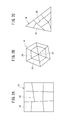
- the porous ceramic structure 10 has, for example, as shown in FIG. 1, one sheet 12 and a porous ceramic aggregate 14 stuck on the sheet 12.
- the porous ceramic aggregate 14 has a plurality of divided porous ceramic particles 16.
- sticking means being fixed in a peelable state, and refers to a state in which the sticking object is separated by releasing a fixed state due to a change with time or an external factor. Therefore, it includes a state where the adhesive is fixed by an adhesive force, and also includes a state where the adhesive is temporarily firmly fixed at the sticking interface. You may stick between the sheet
- Porous means a state that is neither dense nor hollow, and means a state composed of a plurality of pores or particles. Note that the term “dense” refers to a state in which a plurality of fine particles are combined without gaps and does not have pores.
- the hollow means a state in which the inside is hollow and the outer shell portion is dense.
- the aspect ratio of the porous ceramic particles 16 is preferably 3 or more. More preferably, it is 5 or more, more preferably 7 or more. In this case, the aspect ratio refers to the maximum length La / minimum length Lb.
- the maximum length La refers to the maximum length of the widest surface (here, one main surface 16a) among a plurality of surfaces constituting the porous ceramic particles 16. If the wide surface is a square, rectangle, trapezoid, parallelogram, or polygon (pentagon, hexagon, etc.), the longest diagonal is applicable, the circle is the diameter, the ellipse is This corresponds to the length of the long axis.
- the minimum length Lb refers to the thickness ta of the porous ceramic particles 16 as shown in FIG.
- the minimum length Lb is preferably 50 to 500 ⁇ m, more preferably 55 to 400 ⁇ m, more preferably 60 to 300 ⁇ m, and particularly preferably 70 to 200 ⁇ m.
- the sheet 12 for example, an adhesive resin sheet or film can be used, and it is preferable that the sheet 12 can be peeled off due to external factors such as heat, electricity, external force, and the like.
- the porous ceramic aggregate 14 is coated on the object 22 as a bulk body 20 by being coated with a resin material 18 (matrix) such as an adhesive.
- a resin material 18 such as an adhesive
- the planar shape of the porous ceramic aggregate 14 viewed from the top is a planar shape of the area of the object 22 where the porous ceramic aggregate 14 is to be installed (hereinafter referred to as the installation area of the object 22) as viewed from above. Is preferably the same.
- the installation area of the object 22 is a concept including a part of the object 22. “Same” includes a case where they are completely the same or a shape similar to the planar shape of the installation area of the object 22.
- the similar relationship means a shape obtained by enlarging the planar shape of the installation region of the object 22 by 1.1 times to 2.0 times or a shape obtained by reducing 1.1 times to 2.0 times.
- the several porous ceramic particle 16 can be transcribe
- the planar shape viewed from above is a polygonal shape surrounded by a plurality of straight lines 24 (see FIGS. 2A to 5B). There may be at least one ceramic particle 16.
- the planar shape of all the porous ceramic particles 16 may be a polygonal shape surrounded by a plurality of straight lines 24.
- FIG. 2A it may be configured with one type of planar shape, or as shown in FIG. 2B, it may be configured with two types of planar shape. Further, as shown in FIG. 2C, it may be configured with three types of planar shapes.
- FIG. 2A the case where the planar shape of all the porous ceramic particles 16 is a square shape is shown.
- the example of FIG. 2B shows a case where the porous ceramic aggregate 14 is configured by a combination of a square shape and a triangular shape, and shows an example in which six triangular shapes are arranged on the inner side and six rectangular shapes are arranged on the outer side.
- FIG. 2C shows a case where the porous ceramic aggregate 14 is configured by a combination of a triangle shape, a square shape, and a pentagon shape, and an example in which one pentagon shape, two triangle shapes, and five square shapes are arranged. Indicates.
- the ratio of the porous ceramic particles 16 including the curved line 26 in the planar shape seen from the upper surface is as follows. It may be greater than 0% and 50% or less.
- the porous ceramic particles 16 are likely to be displaced when transferring the plurality of porous ceramic particles 16 onto the object 22, but a curve 26 is formed in the porous ceramic aggregate 14. By being partially present, it becomes difficult to shift, and a plurality of porous ceramic particles 16 can be uniformly transferred onto the object 22.
- the ratio of the porous ceramic particles 16 including the curve 26 in the planar shape viewed from the upper surface is determined, the total number Np of the porous ceramic particles 16 on the sheet 12 and the porous ceramic particles 16 including the curve 26 in the planar shape are obtained.
- the number Nw may be counted to calculate (number Nw / number Np) ⁇ 100 (%).
- FIG. 3A of the nine porous ceramic particles 16, seven porous ceramic particles 16 (porous ceramic particles 16 indicated by (1) to (7) in FIG. 3A) have a square shape, and the rest The two porous ceramic particles 16 (the porous ceramic particles 16 indicated by (8) and (9) in FIG. 3A) each include a curved line 26.
- the planar shape of the porous ceramic particles 16) is a quadrangular shape, and the remaining six porous ceramic particles 16 ((1), (2), (15), (19), (23) in FIG. 4A), Curves 26 are included in the planar shape of the porous ceramic particles 16 shown in (24).
- the number of other porous ceramic particles 16 facing the corner of a certain porous ceramic particle 16 is two with respect to the number of corners of the porous ceramic particle 16 included in the porous ceramic aggregate 14.
- the ratio Fa of the number of corner portions is preferably 80% or more. More preferably, it is 90% or more.
- the corner portions may be opposed to each other, or may be in contact with each other.
- the corner portion refers to a bent portion in a planar shape of the porous ceramic particle 16 as viewed from above. Specifically, the part where the boundary between the straight line and the straight line constituting the outer shape of the planar shape is bent, the part where the boundary between the straight line and the curve is bent, and the boundary between the curve and the curve are bent. Refers to the part.
- the location where there are two other porous ceramic particles 16 facing the corners of a certain porous ceramic particle 16 refers to a location having a three-way shape, for example, as indicated by an intersection Ca.
- the crossing part Cb for example, in a cross road-like portion, there are three other porous ceramic particles 16 facing the corners of a certain porous ceramic particle 16.
- the corner that is the target of Na indicates the corner indicated by “ ⁇ ”
- the corner that is the target of Ne indicates the corner indicated by “ ⁇ ”.
- 3A, 4A, and 5A the corners indicated by “ ⁇ ” are 3 other porous ceramic particles 16 that face the corners of a certain porous ceramic particle 16, such as the intersection Cb. A corner included in more than one intersection. Therefore, the corners that are the targets of Nz indicate all the corners indicated by “ ⁇ ”, “ ⁇ ”, and “ ⁇ ”.
- FIGS. 5A and 5B show a porous ceramic aggregate 14 having only three portions of other porous ceramic particles 16 facing the corners of a certain porous ceramic particle 16. .
- Na 0, and thus the above-described ratio Fa is 0%.
- the number of other porous ceramic particles 16 facing two corners of a certain porous ceramic particle 16 increases, and the surface shape of the object 22 is increased. Even if there is a curved surface or unevenness, the plurality of porous ceramic particles 16 can be arranged following the surface shape of the object 22. In addition, since the passage between the plurality of opposed porous ceramic particles 16 is in a complicated branching state, the heat transmitted through the resin material 18 becomes difficult to be transmitted, and a decrease in thermal conductivity can be promoted.
- the porous ceramic aggregate 14 may have a portion 27 in which five or more porous ceramic particles 16 are arranged with one vertex facing each other. Thereby, even if there is a curved surface or unevenness locally on the surface of the object 22, it becomes easy to arrange the plurality of porous ceramic particles 16 along the surface shape of the object 22.
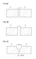
- the gap d (see FIGS. 6A to 6C) between adjacent porous ceramic particles 16 is preferably 0.1 ⁇ m or more and 10 ⁇ m or less.
- the gap d refers to the narrowest gap among the gaps between adjacent porous ceramic particles 16. That is, between the gap d shown in FIG. 6A and the gap d shown in FIG. 6B, the gap d shown in FIG. 6A is narrow and the gap d shown in FIG. 6B is wide.
- the narrow gap da is defined as the gap d between the porous ceramic particles 16.
- the clearance gap d is obtained by measuring between the adjacent porous ceramic particles 16 in the porous ceramic aggregate 14 stuck on the sheet 12 with an optical microscope.
- the inclination angle ⁇ of the side surface of one porous ceramic particle 16 among the adjacent porous ceramic particles 16 is 45 degrees or less with respect to the normal line 28 of the sheet 12, that is, 0 It is preferably not less than 45 degrees and not more than 45 degrees, more preferably not less than 0 degrees and not more than 45 degrees.
- the periphery of the porous ceramic particles 16 is chipped and the fragments 17 are scattered as shown in FIG. 7B. There is.
- the inclination angle ⁇ includes a vertical plane.
- the inclination angle ⁇ is obtained by measuring the inclination angle ⁇ between adjacent porous ceramic particles 16 in the porous ceramic aggregate 14 adhered on the sheet 12 with an optical microscope.
- the number density of the porous ceramic particles 16 in the porous ceramic aggregate 14 is partially different.
- the size of each planar shape of the plurality of porous ceramic particles 16 is different.
- the number density is small (the size of the porous ceramic particles 16 is large), and in the portion where the surface of the object 22 is a curved surface and its periphery, the number density is large (porous).
- the plurality of porous ceramic particles 16 are transferred onto the object 22, the plurality of porous ceramic particles 16 are arranged so as to follow the surface of the object 22. can do.
- the ratio between the maximum value and the minimum value of the number density is preferably larger than 1.2.
- the number density can be calculated as follows. That is, in the porous ceramic aggregate 14 stuck on the sheet 12, 10 arbitrary visual fields are observed with an optical microscope, and the number of porous ceramic particles 16 included in each visual field is measured. Each visual field can adopt a square area of 3 mm ⁇ 3 mm, for example.
- the ratio (maximum value / minimum value) between the maximum value and the minimum value of the size of the planar shape of the porous ceramic particles 16 is preferably larger than 1.2.
- the size of the planar shape of the porous ceramic particles 16 can be calculated as follows. That is, in the porous ceramic aggregate 14 stuck on the sheet 12, 10 arbitrary visual fields are observed with an optical microscope. Then, for each visual field, draw arbitrary five straight lines, measure the length of the line segment in the porous ceramic particles 16 intersecting with the straight lines, and calculate the average value as the size of the porous ceramic particles 16 in the visual field. To do. By comparing the sizes of the porous ceramic particles 16 in these ten visual fields, the maximum value and the minimum value of the size of the porous ceramic particles 16 are extracted, and the ratio (maximum value / minimum value) is calculated.
- the thickness ta (see FIG. 7A) of the plurality of porous ceramic particles 16 included in the porous ceramic aggregate 14 is preferably 1000 ⁇ m or less, and the variation in the thickness ta is preferably 10% or less.
- the thickness ta can be measured using a constant pressure thickness measuring instrument or the like.
- the porous ceramic aggregate 14 when the porous ceramic aggregate 14 is coated with a resin material 18 (matrix) such as an adhesive to form a bulk body 20, the entire porous ceramic aggregate 14 is obtained. Can be easily coated with the resin material 18, and it becomes easy to make the thickness of the resin material 18 on some of the porous ceramic particles 16 uniform. This contributes to lowering the thermal conductivity of the bulk body 20.
- a resin material 18 matrix
- the thickness of the resin material 18 on some of the porous ceramic particles 16 This contributes to lowering the thermal conductivity of the bulk body 20.
- the porosity of the porous ceramic particles 16 is preferably 20 to 99%.
- a pore is at least one of a closed pore and an open pore, and may include both.
- the shape of the pores that is, the surface shape of the opening may be any shape such as a square, a quadrangle, a triangle, a hexagon, and a circle.
- the average pore diameter is preferably 500 nm or less, more preferably 10 to 500 nm. This dimension is effective in inhibiting the generation of lattice vibration (phonon), which is the main cause of heat conduction.
- the porous ceramic particle 16 has a structure in which fine particles are three-dimensionally connected.
- the particle diameter of the fine particles is preferably 1 nm to 5 ⁇ m. More preferably, it is 50 nm to 1 ⁇ m.
- the porous ceramic particles 16 composed of fine particles having a particle diameter in such a range are effective in achieving low thermal conductivity because generation of lattice vibration (phonon), which is a main cause of heat conduction, is hindered.
- the fine particles may be particles (single crystal particles) made of one crystal grain or particles (polycrystalline particles) made of a large number of crystal grains. That is, the porous ceramic particles 16 are preferably a collection of fine particles having a particle size in this range.
- the particle size of the fine particles is the size of one fine particle (the diameter if spherical, the maximum diameter otherwise) in the particle group constituting the skeleton of the porous ceramic particles 16, an image obtained by electron microscope observation. It is measured from.
- the thermal conductivity of the porous ceramic particles 16 is preferably less than 1.5 W / mK, more preferably 0.7 W / mK or less, more preferably 0.5 W / mK or less, particularly preferably 0.3 W. / MK or less.
- the heat capacity of the porous ceramic particles 16 is less than 1000 kJ / m 3 K, more preferably not more than 900kJ / m 3 K, more preferably 800kJ / m 3 K or less, particularly preferably 500 kJ / m 3 K It is as follows.
- the constituent material of the porous ceramic particles 16 preferably includes a metal oxide, and more preferably includes only a metal oxide. This is because when the metal oxide is included, the thermal conductivity tends to be low because the ionic bond between the metal and oxygen is stronger than the metal non-oxide (for example, carbide or nitride).
- the metal non-oxide for example, carbide or nitride
- the metal oxide is an oxide of one element selected from the group consisting of Zr, Y, Al, Si, Ti, Nb, Sr, La, Hf, Ce, Gd, Sm, Mn, Yb, Er, and Ta, or 2
- a composite oxide of the above elements is preferable. This is because when the metal oxide is an oxide or composite oxide of these elements, heat conduction due to lattice vibration (phonon) is less likely to occur.
- ZrO 2 —HfO 2 —Y 2 O 3 ZrO 2 —Y 2 O 3 —La 2 O 3
- ZrO 2 —HfO 2 —Y 2 O 3 La 2 O 3
- HfO 2 —Y 2 O 3 CeO 2 —Y 2 O 3
- Gd 2 Zr 2 O 7 Sm 2 Zr 2 O 7
- LaMnAl 11 O 19 YTa 3 O 9
- Y 0.7 La 0.3 Ta 3 O 9 Y 1.08 Ta 2.76
- Zr Examples include 0.24 O 9 , Y 2 Ti 2 O 7 , LaTa 3 O 9 , Yb 2 Si 2 O 7 , Y 2 Si 2 O 7 , Ti 3 O 5 and the like.
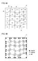
- step S1 of FIG. 8 a pore forming material, a binder, a plasticizer, and a solvent are added to and mixed with the powder of the constituent material of the porous ceramic particles 16 described above to prepare a molding slurry 36 (see FIG. 9). To do.
- step S2 the molding slurry 36 is subjected to vacuum defoaming treatment to adjust the viscosity, and then tape molding is performed to produce a molded body 30 (green sheet) (molded body manufacturing step).
- a molding slurry 36 is placed on a ceramic release polyester film 34 of a doctor blade device 32 shown in FIG. 9 and the fired body 30 (green) is adjusted to a prescribed thickness by a doctor blade 38. Sheet).
- step S3 of FIG. 8 the molded body 30 (green sheet) is peeled off from the polyester film 34 and collected. Since the surface of the polyester film 34 for ceramic release is a mirror surface, the surface of the molded body 30 from which the polyester film 34 is peeled (hereinafter referred to as a peeled surface 30a) is also a mirror surface.
- step S4 the recovered molded body 30 is fired to obtain a sheet-like sintered body 40 (firing step).
- step S5 the sintered body 40 is stuck on the sheet 12 (sticking step).
- the end surface 40a the surface that was the peeling surface 30a of the sintered body 40 in the firing process is also a mirror surface. Therefore, the sintered body 40 is firmly attached to the sheet 12 by attaching the end surface 40 a of the sintered body 40 to the sheet 12.
- step S6 the sintered body 40 is divided into a plurality of porous ceramic particles 16 (a dividing step).
- a porous ceramic structure 10 having one sheet 12 and a porous ceramic aggregate 14 made of a plurality of porous ceramic particles 16 is obtained.
- the surface modification treatment is a treatment for controlling the degree of penetration of the resin material 18 (matrix: see FIG. 11C and FIG. 12) such as an adhesive into the porous ceramic particles 16 (mainly treatment for making it difficult to penetrate). .
- the sintered body 40 is divided into a plurality of small pieces, that is, a plurality of porous ceramic particles 16.
- the blade is pressed against the sintered body 40 and cut (divided) to divide the sintered body 40 into a plurality of porous ceramic particles 16, or the sintered body 40 is cut with a laser to form a plurality of porous ceramic particles. It can be divided by various methods such as dividing into 16. In this case, since the sintered body 40 is firmly adhered to the sheet 12, the sintered body 40 and the porous ceramic particles 16 are prevented from being peeled off from the sheet 12 during the division.
- the second manufacturing method in steps S101 to S103, as in steps S1 to S3 described above, the molding slurry 36 is prepared, the molded body 30 is produced, and the molded body 30 is collected.
- step S104 laser processing or press processing is performed to form a plurality of cuts 42 from the upper surface of the molded body 30.
- steps S105 to S107 the recovered molded body 30 is fired to obtain a sheet-like sintered body 40, and the sintered body 40 is attached to the sheet 12 in the same manner as steps S4 to S6 described above. And dividing into a plurality of porous ceramic particles 16.
- porous ceramic structure 10 having a single sheet 12 and a porous ceramic aggregate 14 made of a plurality of porous ceramic particles 16 is obtained. Also in this second manufacturing method, the surface modification treatment described above may be performed on the sintered body 40 after the firing step or the porous ceramic particles 16 after the dividing step.
- an adhesive 44 is applied on the object 22.
- the porous ceramic structure 10 is placed on the adhesive 44 applied to the object 22.
- the porous ceramic structure 10 is installed with the adhesive 44 on the object 22 and the porous ceramic aggregate 14 facing each other.
- the porous ceramic aggregate 14 is transferred onto the adhesive 44 of the object 22 by, for example, heating the sheet 12 and peeling off the sheet 12.
- the entire porous ceramic aggregate 14 is coated with a resin material 18 (matrix) such as an adhesive to form a bulk body 20. That is, the bulk body 20 is stuck on the object 22.
- a resin material 18 such as an adhesive
- the porous ceramic structure 10 having the porous ceramic aggregate 14 composed of the plurality of porous ceramic particles 16 attached on the sheet 12 is attached to the object 22, Thereafter, the sheet 12 is peeled off, the porous ceramic aggregate 14 is transferred onto the object 22, and the porous ceramic aggregate 14 is coated with a resin material 18 (matrix) such as an adhesive to form the bulk body 20. I am trying to configure it.
- a plurality of porous ceramic particles 16 can be uniformly distributed in the resin material 18. And since the area
- the sintered body 40 adhered to the sheet 12 is divided into a plurality of porous ceramic particles 16, unlike the conventional case, the plurality of porous ceramic particles 16 are uniformly formed on the object 22. Can be arranged. Moreover, even when the surface of the object 22 is irregular (warp or the like) or curved, it is easy to arrange the plurality of porous ceramic particles 16 along the surface shape of the object 22. , Design freedom can be improved. Since the porous ceramic structure 10 is composed of the sheet 12 and the porous ceramic aggregate 14 having the plurality of porous ceramic particles 16 adhered to the sheet 12, the porous ceramic structure 10 Handling is facilitated, and the work of transferring the plurality of porous ceramic particles 16 onto the object 22 is also simplified. This is advantageous for simplifying the manufacturing process.
- the adhesive strength (JIS Z0237) of the sheet 12 is 1.0 N / 10 mm or more, the tensile elongation (JIS K7127) is 0.5% or more, and the thickness is 5 mm or less.
- the adhesive force (JIS Z0237) of the sheet 12 is 1.0 N / 10 mm or more, the tensile elongation (JIS K7127) is 0.5% or more, and the thickness is 5 mm or less.
- the adhesive strength of the sheet 12 is as follows. That is, the adhesive force when holding the porous ceramic particles 16 is 1.0 N / 10 mm or more, and the adhesive force when peeling the porous ceramic particles 16 is 0.1 N / 10 mm or less.
- the method for evaluating the adhesive strength of the sheet 12 is the same as the method for evaluating the adhesive strength of the adhesive tape.
- the sheet 12 is attached to a stainless steel plate, the sheet 12 is pulled 180 ° or 90 °, and the sheet 12 is peeled off from the stainless steel plate.
- the force of time is the adhesive strength.
- the sheet 12 is configured by applying an adhesive to a base material (support).
- the type of the substrate is preferably selected as follows.
- the sheet 12 can be formed on the planar object 22 without any defects.
- the porous ceramic particles 16 When transferring the porous ceramic particles 16 onto the object 22 having a curved surface (convex surface, concave surface, uneven surface), it is preferable to use a cloth, rubber sheet, foam or the like as the substrate. Since the base material of the sheet 12 is soft and stretchable, it is possible to form the film by following the curved surface shape of the sheet 12.
- the sheet 12 can be easily peeled off by applying heat, water, a solvent, light (ultraviolet light), and microwaves to weaken the adhesive force.
- the adhesive strength of the sheet 12 is preferably weaker than the adhesive 44 used between the object 22 and the porous ceramic structure 10.
- the bulk body 20 is configured. In this case, the thermal conductivity of each bulk body 20 and the ease of following the curved surface were confirmed.
- Example 1 As the plurality of porous ceramic particles 16 constituting the porous ceramic structure 10, porous ceramic particles 16 each having a porosity of 60% and a thickness of 60 ⁇ m were used, and Example 1 was applied according to the above-described first production method.
- Example 1 a porous ceramic structure 10 for measuring porosity and a porous ceramic structure 10 for bulk body were produced as follows. The same applies to Example 2, Reference Examples 1 and 2, Comparative Example 1 and Comparative Example 2 described later.
- yttria partially stabilized zirconia powder, pore former (latex particles or melamine resin particles), polyvinyl butyral resin (PVB) as a binder, DOP (dioctyl phthalate) as a plasticizer, xylene as a solvent and 1- Butanol was added and mixed in a ball mill for 30 hours to prepare a molding slurry 36.
- the molding slurry 36 was subjected to vacuum defoaming treatment to adjust the viscosity to 4000 cps, and then a molded body 30 (green sheet) was prepared by the doctor blade device 32 so that the thickness after firing was 60 ⁇ m. . Thereafter, the molded body 30 was fired at 1100 ° C.
- the sintered body 40 was adhered to the upper surface of the sheet 12. Further, the sintered body 40 was divided to produce a plurality of porous ceramic particles 16. That is, the porous ceramic structure 10 in which the porous ceramic aggregate 14 composed of a plurality of porous ceramic particles 16 was stuck on the sheet 12 was produced.
- the planar shape of the porous ceramic aggregate 14 on the sheet 12 is a square shape having a length of 100 mm and a width of 100 mm.
- about 40000 porous ceramic particles 16 are arranged on the sheet 12. It has become a form.
- the number of corners of the porous ceramic particles 16 included in the porous ceramic aggregate 14 is opposite to the corners of the porous ceramic particles 16.
- the ratio Fa of the number of corners at the location where the number of the porous ceramic particles 16 is two was 90%.
- Example 2 As the porous ceramic structure 10, a bulk body 20 according to Example 2 was produced in the same manner as in Example 1 except that the ratio Fa was 80%.
- the porous ceramic structure 10 does not have a portion where two other porous ceramic particles 16 facing the corners of a certain porous ceramic particle 16 (that is, the intersecting portion Ca) exist, and a plurality of porous ceramic structures.
- a bulk body 20 according to Comparative Example 1 was produced in the same manner as in Example 1 except that a porous ceramic structure in which the particles 16 were arranged in a lattice shape was used.
- Comparative Example 2 As shown in FIG. 13A, after preparing a slurry 50 containing particles 52 (commercially available porous ceramic particles) having a porosity of 90% and a particle size of 50 ⁇ m, polystyrene resin fine particles and water, poured into a mold and dried The bulk body 54 according to Comparative Example 2 was manufactured by firing and solidifying.
- particles 52 commercially available porous ceramic particles
- the bulk body 54 according to Comparative Example 2 was manufactured by firing and solidifying.
- the average pore diameter of the porous ceramic particles 16 was measured using an automatic porosimeter (trade name “Autopore 9200”) manufactured by Shimadzu Corporation.
- Comparative Example 2 had a high thermal conductivity of 2.0 W / mK or higher. This is probably because the bulk body 54 according to the comparative example 2 has a high thermal conductivity because there are many regions 58 of only the adhesive 56. Comparative Example 1 also had a high thermal conductivity of 1.5 W / mK or higher. This is because the bulk body 54 according to the comparative example 1 has a form in which the passages between the plurality of opposed porous ceramic particles 16 linearly extend over the entire porous ceramic aggregate 14. It is thought that the heat that transmits is easier to transfer.
- Examples 1 and 2 and Reference Examples 1 and 2 all have a low thermal conductivity of 1.4 W / mK or less, and in particular, Examples 1 and 2 have a thermal conductivity of 0.9 W / m. It was very low at mK. This is because the passage between the plurality of opposed porous ceramic particles 16 is in a complicated branching state, so that the heat transmitted through the resin material 18 becomes difficult to be transmitted, and the decrease in thermal conductivity is promoted. .
- Example 1 Among Examples 1 and 2, Reference Examples 1 and 2, and Comparative Example 1, the ease of following the curved surface of the object 22 is high for Examples 1 and 2, and Example 1 has the highest evaluation. it was high. In Reference Examples 1 and 2, since the ratio Fa was less than 80%, the number of intersecting portions Ca and Cb was small, and it is considered that the followability to the surface of the object 22 was lowered.
- porous ceramic structure according to the present invention is not limited to the above-described embodiment, and can of course have various configurations without departing from the gist of the present invention.
- the porous ceramic aggregate 14 is coated with the resin material 18, but in addition, a part of the porous ceramic aggregate 14 is coated with the resin material 18 to form the bulk body. 20 may be used, or the bulk material 20 may be formed by simply installing the porous ceramic aggregate 14 on the object 22 without using the resin material 18.
Landscapes
- Chemical & Material Sciences (AREA)
- Engineering & Computer Science (AREA)
- Ceramic Engineering (AREA)
- Structural Engineering (AREA)
- Materials Engineering (AREA)
- Organic Chemistry (AREA)
- Manufacturing & Machinery (AREA)
- Inorganic Chemistry (AREA)
- Nanotechnology (AREA)
- Composite Materials (AREA)
- Mechanical Engineering (AREA)
- Chemical Kinetics & Catalysis (AREA)
- Porous Artificial Stone Or Porous Ceramic Products (AREA)
- Laminated Bodies (AREA)
- Devices For Post-Treatments, Processing, Supply, Discharge, And Other Processes (AREA)
- Producing Shaped Articles From Materials (AREA)
Abstract
Description
Na/(Nz-Nb)×100(%)≧80(%)
である。
Fa=Na/(Nz-Ne)×100(%)
(a) 粘着力が高いほど多孔質セラミック粒子16を強固に固定することができる。
(b) 引張伸度が高いほど曲面に追従させることができる。
(c) 厚みが薄いほど曲面に追従させやすい。
多孔質セラミック構造体10を構成する複数の多孔質セラミック粒子16として、それぞれ気孔率が60%、厚みが60μmの多孔質セラミック粒子16を使用し、上述した第1製造方法に準じて実施例1に係るバルク体20を作製した。すなわち、先ず、シート12と、該シート12の1つの面に貼着された複数の多孔質セラミック粒子16とを有する多孔質セラミック構造体10を使用した。そして、対象物22に接着剤44(熱伝導率2W/mK)を塗布した後、上記シート12を使って、対象物22の接着剤44上に複数の多孔質セラミック粒子16を転写し、熱をかけることでシート12を剥がした。その上から樹脂材18(マトリックス)を塗布した後、樹脂材18を固化して、対象物22の表面にバルク体20を設置した。
実施例1において、気孔率測定用の多孔質セラミック構造体10とバルク体用の多孔質セラミック構造体10を以下のようにして作製した。これは、後述する実施例2、参考例1、2、比較例1及び比較例2についても同様である。
多孔質セラミック構造体10として、上記割合Faが80%である点以外は、実施例1と同様にして実施例2に係るバルク体20を作製した。
多孔質セラミック構造体10として、上記割合Faが70%である点以外は、実施例1と同様にして参考例1に係るバルク体20を作製した。
多孔質セラミック構造体10として、上記割合Faが50%である点以外は、実施例1と同様にして参考例2に係るバルク体20を作製した。
多孔質セラミック構造体10として、ある多孔質セラミック粒子16の角部と対向する他の多孔質セラミック粒子16が2個である箇所(すなわち、交差部Ca)が存在せず、複数の多孔質セラミック粒子16が格子状に配置された多孔質セラミック構造体を使用した点以外は、実施例1と同様にして比較例1に係るバルク体20を作製した。
図13Aに示すように、気孔率が90%、粒径が50μmの粒子52(市販の多孔質セラミック粒子)と、ポリスチレン樹脂微粒子及び水を含むスラリー50を調製した後、型に流し込み、乾燥後、焼成、固化して比較例2に係るバルク体54を作製した。
<気孔率の計測>
実施例1、2、参考例1、2及び比較例1については、気孔率測定用の多孔質セラミック構造体10を構成する複数の多孔質セラミック粒子16から無作為に10個の多孔質セラミック粒子16を選んで樹脂に埋込み、電子顕微鏡にて多孔質セラミック粒子16を観察することができる観察箇所まで研磨して、樹脂埋め研磨面とした。そして、この樹脂埋め研磨面に対して電子顕微鏡観察(画像解析)を行った。画像解析より、10個の多孔質セラミック粒子16の各気孔率を算出し、10個分の多孔質セラミック粒子16の平均値を多孔質セラミック粒子16の気孔率とした。
多孔質セラミック粒子16の平均気孔径を、株式会社島津製作所の自動ポロシメータ(商品名「オートポア9200」)を使用して計測した。
先ず、水銀ポロシメータでバルク体20の密度を測定した。次に、DSC(Differential Scanning Calorimeter)法でバルク体20の比熱を測定した。次に、レーザーフラッシュ法でバルク体20の熱拡散率を測定した。その後、熱拡散率×比熱×密度=熱伝導率の関係式から、バルク体20の熱伝導率を算出し、以下の評価基準に基づいて、実施例1、2、参考例1、2並びに比較例1及び2を評価した。
A:0.9W/mK以下
B:1.0W/mK以上1.4W/mK以下
C:1.5W/mK以上1.9W/m以下
D:2.0W/mK以上
対象物22上に存在する多孔質セラミック粒子16のうち、周辺部が浮いている多孔質セラミック粒子16の個数Nbを光学顕微鏡で確認し、シート12上の多孔質セラミック粒子16の全個数Nzに対する個数Nbの割合、すなわち、(個数Nb/全個数Nz)×100(%)を求めた。そして、以下の評価基準に基づいて、実施例1、2、参考例1、2、比較例1を評価した。なお、比較例2は、接着剤56中に粒径が50μmの粒子52を含むバルク体54であって、粒子52が対象物22に貼着される性質のものでないため、この追従のし易さの評価から外した。
A:3%未満
B:3%以上5%未満
C:5%以上10%未満
D:10%以上
実施例1及び2、参考例1及び2並びに比較例1及び2の内訳及び評価結果を下記表1に示す。

Claims (8)
- 少なくとも複数の多孔質セラミック粒子(16)にて構成された多孔質セラミック集合体(14)を有し、
前記多孔質セラミック集合体(14)内に含まれる前記多孔質セラミック粒子(16)の角部の個数に対して、ある多孔質セラミック粒子(16)の角部と対向する他の多孔質セラミック粒子(16)が2個である箇所の角部の個数の割合が80%以上であることを特徴とする多孔質セラミック構造体。 - 請求項1記載の多孔質セラミック構造体において、
前記多孔質セラミック集合体(14)に含まれる全ての前記多孔質セラミック粒子(16)の角部の合計をNz、前記多孔質セラミック集合体(14)のうち、ある多孔質セラミック粒子(16)の角部と対向する他の多孔質セラミック粒子(16)が2個である箇所の角部の個数をNa、前記多孔質セラミック集合体(14)の周囲に位置する角部の数をNeとしたとき、
Na/(Nz-Ne)×100(%)≧80(%)
であることを特徴とする多孔質セラミック構造体。 - 請求項2記載の多孔質セラミック構造体において、
Na/(Nz-Ne)×100(%)≧90(%)
であることを特徴とする多孔質セラミック構造体。 - 請求項1~3のいずれか1項に記載の多孔質セラミック構造体において、
1つのシート(12)と、
前記シート(12)上に貼着された前記多孔質セラミック集合体(14)とを有することを特徴とする多孔質セラミック構造体。 - 請求項1~4のいずれか1項に記載の多孔質セラミック構造体において、
前記多孔質セラミック粒子(16)の気孔率が20~99%であることを特徴とする多孔質セラミック構造体。 - 請求項1~5のいずれか1項に記載の多孔質セラミック構造体において、
前記多孔質セラミック粒子(16)の平均気孔径が500nm以下であることを特徴とする多孔質セラミック構造体。 - 請求項1~6のいずれか1項に記載の多孔質セラミック構造体において、
前記多孔質セラミック粒子(16)の熱伝導率が1.5W/mK未満であることを特徴とする多孔質セラミック構造体。 - 請求項1~7のいずれか1項に記載の多孔質セラミック構造体において、
前記多孔質セラミック粒子(16)の熱容量が1000kJ/m3K以下であることを特徴とする多孔質セラミック構造体。
Priority Applications (4)
| Application Number | Priority Date | Filing Date | Title |
|---|---|---|---|
| CN201680041453.6A CN107848899A (zh) | 2015-07-16 | 2016-06-02 | 多孔质陶瓷结构体 |
| JP2017506418A JP6220099B2 (ja) | 2015-07-16 | 2016-06-02 | 多孔質セラミック構造体 |
| DE112016003205.6T DE112016003205B9 (de) | 2015-07-16 | 2016-06-02 | Poröse keramische struktur |
| US15/869,611 US10611696B2 (en) | 2015-07-16 | 2018-01-12 | Porous ceramic structure |
Applications Claiming Priority (4)
| Application Number | Priority Date | Filing Date | Title |
|---|---|---|---|
| JP2015141897 | 2015-07-16 | ||
| JP2015-141897 | 2015-07-16 | ||
| JP2015235495 | 2015-12-02 | ||
| JP2015-235495 | 2015-12-02 |
Related Child Applications (1)
| Application Number | Title | Priority Date | Filing Date |
|---|---|---|---|
| US15/869,611 Continuation US10611696B2 (en) | 2015-07-16 | 2018-01-12 | Porous ceramic structure |
Publications (1)
| Publication Number | Publication Date |
|---|---|
| WO2017010186A1 true WO2017010186A1 (ja) | 2017-01-19 |
Family
ID=57756920
Family Applications (2)
| Application Number | Title | Priority Date | Filing Date |
|---|---|---|---|
| PCT/JP2016/066507 Ceased WO2017010186A1 (ja) | 2015-07-16 | 2016-06-02 | 多孔質セラミック構造体 |
| PCT/JP2016/066506 Ceased WO2017010185A1 (ja) | 2015-07-16 | 2016-06-02 | 多孔質セラミック構造体 |
Family Applications After (1)
| Application Number | Title | Priority Date | Filing Date |
|---|---|---|---|
| PCT/JP2016/066506 Ceased WO2017010185A1 (ja) | 2015-07-16 | 2016-06-02 | 多孔質セラミック構造体 |
Country Status (5)
| Country | Link |
|---|---|
| US (2) | US10611696B2 (ja) |
| JP (4) | JP6220099B2 (ja) |
| CN (2) | CN107848899A (ja) |
| DE (2) | DE112016003205B9 (ja) |
| WO (2) | WO2017010186A1 (ja) |
Cited By (2)
| Publication number | Priority date | Publication date | Assignee | Title |
|---|---|---|---|---|
| JP2019075507A (ja) * | 2017-10-18 | 2019-05-16 | 日本碍子株式会社 | 放熱部材、放熱構造及び電子機器 |
| EP3492442A4 (en) * | 2016-07-29 | 2020-04-01 | NGK Insulators, Ltd. | POROUS CERAMIC PARTICLES AND POROUS CERAMIC STRUCTURE |
Families Citing this family (2)
| Publication number | Priority date | Publication date | Assignee | Title |
|---|---|---|---|---|
| CN110461798A (zh) * | 2017-03-29 | 2019-11-15 | 日本碍子株式会社 | 多孔质陶瓷颗粒及多孔质陶瓷结构体 |
| CN120956313A (zh) * | 2018-09-19 | 2025-11-14 | 阿卡什系统公司 | 用于卫星通信的系统和方法 |
Citations (2)
| Publication number | Priority date | Publication date | Assignee | Title |
|---|---|---|---|---|
| JPS5413621A (en) * | 1977-07-01 | 1979-02-01 | Kubota Ltd | Ornamental roof material and making method thereof |
| JP2014503367A (ja) * | 2010-11-01 | 2014-02-13 | スリーエム イノベイティブ プロパティズ カンパニー | 成形セラミック研磨粒子を製造するためのレーザー方法、成形セラミック研磨粒子、及び研磨物品 |
Family Cites Families (21)
| Publication number | Priority date | Publication date | Assignee | Title |
|---|---|---|---|---|
| JPS62232187A (ja) * | 1986-04-02 | 1987-10-12 | 松下電器産業株式会社 | セラミツク基板の製造方法 |
| JP2765783B2 (ja) * | 1992-05-01 | 1998-06-18 | 株式会社クボタ | セメント系板材表面の凹凸模様付方法 |
| EP0653392B1 (en) * | 1993-05-20 | 1998-10-14 | Sumitomo Electric Industries, Ltd | Porous ceramic and process for producing the same |
| JPH07164417A (ja) * | 1993-12-15 | 1995-06-27 | Murata Mfg Co Ltd | セラミックグリーンシートの製造方法 |
| JPH11216713A (ja) * | 1998-01-30 | 1999-08-10 | Nichiha Corp | 無機質板 |
| JP2000202819A (ja) * | 1999-01-11 | 2000-07-25 | Sumitomo Metal Electronics Devices Inc | 2分割構造のグリ―ンシ―ト |
| JP4755754B2 (ja) * | 2000-12-06 | 2011-08-24 | 株式会社東芝 | 窒化珪素基板およびそれを用いた窒化珪素回路基板並びにその製造方法 |
| JP4398142B2 (ja) * | 2001-12-07 | 2010-01-13 | 日本碍子株式会社 | セラミック多孔体及びその結合材に使用するガラスの製造方法 |
| JP2004010903A (ja) | 2003-10-06 | 2004-01-15 | Nagashima Tokushu Toryo Kk | 遮熱性塗料 |
| JP2006173368A (ja) * | 2004-12-16 | 2006-06-29 | Sony Corp | セラミック基板 |
| JP4870558B2 (ja) * | 2004-12-27 | 2012-02-08 | イビデン株式会社 | ハニカム構造体及びシール材層 |
| KR100855167B1 (ko) * | 2005-11-18 | 2008-08-29 | 이비덴 가부시키가이샤 | 벌집형 구조체 |
| BRPI0621318B1 (pt) * | 2006-02-10 | 2017-10-10 | Saint-Gobain Ceramics & Plastics, Inc | Process for the manufacture of porosa ceramic material |
| KR20130038958A (ko) * | 2008-07-22 | 2013-04-18 | 생-고벵 아브라시프 | 집합체들을 함유하는 코팅된 연마 제품들 |
| JP5495545B2 (ja) * | 2008-08-28 | 2014-05-21 | 京セラ株式会社 | 多孔質セラミック部材およびその製法ならびにフィルタ |
| JP2010064945A (ja) | 2008-09-12 | 2010-03-25 | Toyohashi Univ Of Technology | セラミック複合粒子の製造法および機能性セラミック複合材料 |
| JP2010155946A (ja) | 2008-12-29 | 2010-07-15 | Dow Corning Toray Co Ltd | 硬化性オルガノポリシロキサン組成物および多孔質オルガノポリシロキサン硬化物 |
| JP5559023B2 (ja) * | 2010-12-15 | 2014-07-23 | 日本特殊陶業株式会社 | 配線基板及びその製造方法 |
| JP2013102035A (ja) * | 2011-11-08 | 2013-05-23 | Ngk Spark Plug Co Ltd | セラミック基板およびその製造方法 |
| EP2865722B1 (en) * | 2012-06-20 | 2019-03-13 | NGK Insulators, Ltd. | Porous plate-shaped filler, coating composition, heat-insulating film, and heat-insulating film structure |
| WO2014071346A1 (en) * | 2012-11-05 | 2014-05-08 | University Of Virginia Patent Foundation | Porous metal ceramic materials and methods for making and using the same |
-
2016
- 2016-06-02 WO PCT/JP2016/066507 patent/WO2017010186A1/ja not_active Ceased
- 2016-06-02 CN CN201680041453.6A patent/CN107848899A/zh active Pending
- 2016-06-02 JP JP2017506418A patent/JP6220099B2/ja active Active
- 2016-06-02 JP JP2017506416A patent/JP6231721B2/ja active Active
- 2016-06-02 CN CN201680041452.1A patent/CN107835796B/zh active Active
- 2016-06-02 DE DE112016003205.6T patent/DE112016003205B9/de not_active Expired - Fee Related
- 2016-06-02 WO PCT/JP2016/066506 patent/WO2017010185A1/ja not_active Ceased
- 2016-06-02 DE DE112016003197.1T patent/DE112016003197B4/de active Active
-
2017
- 2017-09-28 JP JP2017187334A patent/JP2018016541A/ja active Pending
- 2017-10-19 JP JP2017202464A patent/JP2018058758A/ja active Pending
-
2018
- 2018-01-12 US US15/869,611 patent/US10611696B2/en not_active Expired - Fee Related
- 2018-01-12 US US15/869,554 patent/US10597336B2/en active Active
Patent Citations (2)
| Publication number | Priority date | Publication date | Assignee | Title |
|---|---|---|---|---|
| JPS5413621A (en) * | 1977-07-01 | 1979-02-01 | Kubota Ltd | Ornamental roof material and making method thereof |
| JP2014503367A (ja) * | 2010-11-01 | 2014-02-13 | スリーエム イノベイティブ プロパティズ カンパニー | 成形セラミック研磨粒子を製造するためのレーザー方法、成形セラミック研磨粒子、及び研磨物品 |
Cited By (3)
| Publication number | Priority date | Publication date | Assignee | Title |
|---|---|---|---|---|
| EP3492442A4 (en) * | 2016-07-29 | 2020-04-01 | NGK Insulators, Ltd. | POROUS CERAMIC PARTICLES AND POROUS CERAMIC STRUCTURE |
| JP2019075507A (ja) * | 2017-10-18 | 2019-05-16 | 日本碍子株式会社 | 放熱部材、放熱構造及び電子機器 |
| JP7133916B2 (ja) | 2017-10-18 | 2022-09-09 | 日本碍子株式会社 | 放熱部材、放熱構造及び電子機器 |
Also Published As
| Publication number | Publication date |
|---|---|
| US10611696B2 (en) | 2020-04-07 |
| DE112016003205T5 (de) | 2018-04-05 |
| JP6231721B2 (ja) | 2017-11-15 |
| CN107848899A (zh) | 2018-03-27 |
| US20180134631A1 (en) | 2018-05-17 |
| CN107835796B (zh) | 2020-12-01 |
| DE112016003197T5 (de) | 2018-04-05 |
| WO2017010185A1 (ja) | 2017-01-19 |
| JP6220099B2 (ja) | 2017-10-25 |
| DE112016003197B4 (de) | 2025-11-20 |
| JP2018058758A (ja) | 2018-04-12 |
| JPWO2017010186A1 (ja) | 2017-07-13 |
| DE112016003205B4 (de) | 2019-05-09 |
| CN107835796A (zh) | 2018-03-23 |
| DE112016003205B9 (de) | 2019-08-29 |
| US10597336B2 (en) | 2020-03-24 |
| JPWO2017010185A1 (ja) | 2017-07-20 |
| JP2018016541A (ja) | 2018-02-01 |
| US20180141872A1 (en) | 2018-05-24 |
Similar Documents
| Publication | Publication Date | Title |
|---|---|---|
| JP6220099B2 (ja) | 多孔質セラミック構造体 | |
| EP3133052A1 (en) | Porous plate-like filler, heat insulation film and method for producing porous plate-like filler | |
| JP6714433B2 (ja) | 多孔質セラミック構造体及びその製造方法 | |
| CN107459273B (zh) | 多孔质陶瓷结构体 | |
| US20190152862A1 (en) | Porous ceramic particle and porous ceramic structure | |
| US20200002237A1 (en) | Porous ceramic particle and porous ceramic structure | |
| JP6126765B1 (ja) | 多孔質セラミック粒子 | |
| US10933560B2 (en) | Intermediate member | |
| JP6648994B2 (ja) | 複合粒子体および焼成体の製造方法 |
Legal Events
| Date | Code | Title | Description |
|---|---|---|---|
| ENP | Entry into the national phase |
Ref document number: 2017506418 Country of ref document: JP Kind code of ref document: A |
|
| 121 | Ep: the epo has been informed by wipo that ep was designated in this application |
Ref document number: 16824166 Country of ref document: EP Kind code of ref document: A1 |
|
| WWE | Wipo information: entry into national phase |
Ref document number: 112016003205 Country of ref document: DE |
|
| 122 | Ep: pct application non-entry in european phase |
Ref document number: 16824166 Country of ref document: EP Kind code of ref document: A1 |