WO2017010237A1 - Procédé de forgeage d'élément d'arbre de joint homocinétique - Google Patents
Procédé de forgeage d'élément d'arbre de joint homocinétique Download PDFInfo
- Publication number
- WO2017010237A1 WO2017010237A1 PCT/JP2016/068240 JP2016068240W WO2017010237A1 WO 2017010237 A1 WO2017010237 A1 WO 2017010237A1 JP 2016068240 W JP2016068240 W JP 2016068240W WO 2017010237 A1 WO2017010237 A1 WO 2017010237A1
- Authority
- WO
- WIPO (PCT)
- Prior art keywords
- constant velocity
- velocity universal
- universal joint
- shaft member
- forging
- Prior art date
- Legal status (The legal status is an assumption and is not a legal conclusion. Google has not performed a legal analysis and makes no representation as to the accuracy of the status listed.)
- Ceased
Links
Images










Classifications
-
- B—PERFORMING OPERATIONS; TRANSPORTING
- B21—MECHANICAL METAL-WORKING WITHOUT ESSENTIALLY REMOVING MATERIAL; PUNCHING METAL
- B21K—MAKING FORGED OR PRESSED METAL PRODUCTS, e.g. HORSE-SHOES, RIVETS, BOLTS OR WHEELS
- B21K1/00—Making machine elements
- B21K1/06—Making machine elements axles or shafts
-
- B—PERFORMING OPERATIONS; TRANSPORTING
- B21—MECHANICAL METAL-WORKING WITHOUT ESSENTIALLY REMOVING MATERIAL; PUNCHING METAL
- B21J—FORGING; HAMMERING; PRESSING METAL; RIVETING; FORGE FURNACES
- B21J13/00—Details of machines for forging, pressing, or hammering
- B21J13/02—Dies or mountings therefor
-
- B—PERFORMING OPERATIONS; TRANSPORTING
- B21—MECHANICAL METAL-WORKING WITHOUT ESSENTIALLY REMOVING MATERIAL; PUNCHING METAL
- B21J—FORGING; HAMMERING; PRESSING METAL; RIVETING; FORGE FURNACES
- B21J13/00—Details of machines for forging, pressing, or hammering
- B21J13/02—Dies or mountings therefor
- B21J13/03—Die mountings
-
- B—PERFORMING OPERATIONS; TRANSPORTING
- B21—MECHANICAL METAL-WORKING WITHOUT ESSENTIALLY REMOVING MATERIAL; PUNCHING METAL
- B21J—FORGING; HAMMERING; PRESSING METAL; RIVETING; FORGE FURNACES
- B21J5/00—Methods for forging, hammering, or pressing; Special equipment or accessories therefor
- B21J5/06—Methods for forging, hammering, or pressing; Special equipment or accessories therefor for performing particular operations
- B21J5/08—Upsetting
-
- B—PERFORMING OPERATIONS; TRANSPORTING
- B21—MECHANICAL METAL-WORKING WITHOUT ESSENTIALLY REMOVING MATERIAL; PUNCHING METAL
- B21K—MAKING FORGED OR PRESSED METAL PRODUCTS, e.g. HORSE-SHOES, RIVETS, BOLTS OR WHEELS
- B21K1/00—Making machine elements
- B21K1/14—Making machine elements fittings
-
- B—PERFORMING OPERATIONS; TRANSPORTING
- B21—MECHANICAL METAL-WORKING WITHOUT ESSENTIALLY REMOVING MATERIAL; PUNCHING METAL
- B21K—MAKING FORGED OR PRESSED METAL PRODUCTS, e.g. HORSE-SHOES, RIVETS, BOLTS OR WHEELS
- B21K1/00—Making machine elements
- B21K1/76—Making machine elements elements not mentioned in one of the preceding groups
- B21K1/762—Coupling members for conveying mechanical motion, e.g. universal joints
- B21K1/765—Outer elements of coupling members
-
- F—MECHANICAL ENGINEERING; LIGHTING; HEATING; WEAPONS; BLASTING
- F16—ENGINEERING ELEMENTS AND UNITS; GENERAL MEASURES FOR PRODUCING AND MAINTAINING EFFECTIVE FUNCTIONING OF MACHINES OR INSTALLATIONS; THERMAL INSULATION IN GENERAL
- F16D—COUPLINGS FOR TRANSMITTING ROTATION; CLUTCHES; BRAKES
- F16D1/00—Couplings for rigidly connecting two coaxial shafts or other movable machine elements
- F16D1/02—Couplings for rigidly connecting two coaxial shafts or other movable machine elements for connecting two abutting shafts or the like
- F16D1/027—Couplings for rigidly connecting two coaxial shafts or other movable machine elements for connecting two abutting shafts or the like non-disconnectable, e.g. involving gluing, welding or the like
-
- F—MECHANICAL ENGINEERING; LIGHTING; HEATING; WEAPONS; BLASTING
- F16—ENGINEERING ELEMENTS AND UNITS; GENERAL MEASURES FOR PRODUCING AND MAINTAINING EFFECTIVE FUNCTIONING OF MACHINES OR INSTALLATIONS; THERMAL INSULATION IN GENERAL
- F16D—COUPLINGS FOR TRANSMITTING ROTATION; CLUTCHES; BRAKES
- F16D3/00—Yielding couplings, i.e. with means permitting movement between the connected parts during the drive
- F16D3/16—Universal joints in which flexibility is produced by means of pivots or sliding or rolling connecting parts
- F16D3/20—Universal joints in which flexibility is produced by means of pivots or sliding or rolling connecting parts one coupling part entering a sleeve of the other coupling part and connected thereto by sliding or rolling members
- F16D3/22—Universal joints in which flexibility is produced by means of pivots or sliding or rolling connecting parts one coupling part entering a sleeve of the other coupling part and connected thereto by sliding or rolling members the rolling members being balls, rollers, or the like, guided in grooves or sockets in both coupling parts
- F16D3/223—Universal joints in which flexibility is produced by means of pivots or sliding or rolling connecting parts one coupling part entering a sleeve of the other coupling part and connected thereto by sliding or rolling members the rolling members being balls, rollers, or the like, guided in grooves or sockets in both coupling parts the rolling members being guided in grooves in both coupling parts
- F16D3/226—Universal joints in which flexibility is produced by means of pivots or sliding or rolling connecting parts one coupling part entering a sleeve of the other coupling part and connected thereto by sliding or rolling members the rolling members being balls, rollers, or the like, guided in grooves or sockets in both coupling parts the rolling members being guided in grooves in both coupling parts the groove centre-lines in each coupling part lying on a cylinder co-axial with the respective coupling part
- F16D3/227—Universal joints in which flexibility is produced by means of pivots or sliding or rolling connecting parts one coupling part entering a sleeve of the other coupling part and connected thereto by sliding or rolling members the rolling members being balls, rollers, or the like, guided in grooves or sockets in both coupling parts the rolling members being guided in grooves in both coupling parts the groove centre-lines in each coupling part lying on a cylinder co-axial with the respective coupling part the joints being telescopic
-
- F—MECHANICAL ENGINEERING; LIGHTING; HEATING; WEAPONS; BLASTING
- F16—ENGINEERING ELEMENTS AND UNITS; GENERAL MEASURES FOR PRODUCING AND MAINTAINING EFFECTIVE FUNCTIONING OF MACHINES OR INSTALLATIONS; THERMAL INSULATION IN GENERAL
- F16D—COUPLINGS FOR TRANSMITTING ROTATION; CLUTCHES; BRAKES
- F16D3/00—Yielding couplings, i.e. with means permitting movement between the connected parts during the drive
- F16D3/16—Universal joints in which flexibility is produced by means of pivots or sliding or rolling connecting parts
- F16D3/20—Universal joints in which flexibility is produced by means of pivots or sliding or rolling connecting parts one coupling part entering a sleeve of the other coupling part and connected thereto by sliding or rolling members
- F16D3/22—Universal joints in which flexibility is produced by means of pivots or sliding or rolling connecting parts one coupling part entering a sleeve of the other coupling part and connected thereto by sliding or rolling members the rolling members being balls, rollers, or the like, guided in grooves or sockets in both coupling parts
- F16D3/223—Universal joints in which flexibility is produced by means of pivots or sliding or rolling connecting parts one coupling part entering a sleeve of the other coupling part and connected thereto by sliding or rolling members the rolling members being balls, rollers, or the like, guided in grooves or sockets in both coupling parts the rolling members being guided in grooves in both coupling parts
- F16D2003/22326—Attachments to the outer joint member, i.e. attachments to the exterior of the outer joint member or to the shaft of the outer joint member
Definitions
- This invention relates to a method for forging a shaft member of a constant velocity universal joint.
- Some power transmission shafts and other shaft-shaped products have a part with a large outer diameter relative to the shaft (hereinafter referred to as “expanded portion”). By upsetting the part by forging, it is expected to improve the material yield and simplify the removal process. Some products have a plurality (two or more) of enlarged diameter portions in the shaft portion.
- As a forging technique for forming an enlarged diameter portion conventionally, processing using an upsetter forging machine is known (for example, Patent Document 1).
- FIG. 13 shows an example in which a shaft member having two enlarged diameter portions at both ends of the shaft portion is processed by an upsetter forging machine.
- one of the enlarged diameter parts is formed by an upsetter forging machine.
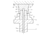
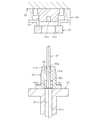
- the base material 101 formed with one enlarged-diameter portion 101a is carried between the grip dies 100, and as shown in FIG. 13B, the grip die 100 is closed and the base material 101 is gripped.
- the remaining diameter-expanded portion 101b is formed by applying pressure with the punch 102.
- FIGS. 13d and 13e The reaction force when pressed by the punch 102 needs to be generated by the gripping force of the gripping die 100.
- a gap ⁇ needs to be provided between the grip dies 100 facing each other in order to grip the billet or the shaped material.
- FIG. 13e is a cross-sectional view taken along the line BB of FIG. 13d. Since there is a gap ⁇ between the opposing grip dies 100, the material flows into the gap ⁇ when the punch 102 is pressed, and the convex portion 101c remains on the outer diameter of the product. For this reason, some products need to be removed in a later step.
- the grasped shape material 101 may be displaced in the pressurizing direction of the punch 102 during molding, and the overall length of the product is not stable. Therefore, depending on the product, it is necessary to set a large allowance. Furthermore, since the upsetter forging machine is a dedicated machine having a complicated mechanism, the equipment cost is expensive. Various investigations were made focusing on these problems.
- the present invention has been proposed in view of the above-described problems, and a shaft member of a constant velocity universal joint that aims to improve the yield and accuracy of a shaft member having a plurality of diameter-expanded portions in the shaft portion and to reduce the manufacturing cost.
- An object of the present invention is to provide a forging method.
- the present inventors have made various studies and divided dies for housing a shape member of a shaft member of a constant velocity universal joint in which a part of the plurality of enlarged diameter portions is formed.
- the present invention has been achieved by a new idea that enables the application of a general-purpose machine that restrains the shape material and supports the pressing force of the punch with the work receiving member.
- the present invention provides a method for forging a shaft member of a constant velocity universal joint having a plurality of diameter-expanded portions in a shaft portion, wherein the forging method includes the plurality of diameter-expanded portions.
- the remaining diameter-enlarged portion is formed on a shape material in which a part of the diameter-increased portion is preliminarily formed.
- a punch and the one of the shape materials are formed.
- a workpiece receiving member that accommodates the divided die having a molding surface while accommodating the enlarged diameter portion and the shaft portion of the part, and placing the partial enlarged diameter portion of the shaped member and supporting the pressing force of the punch, After placing the shaped material formed with the part of the enlarged diameter portion on the work receiving member, the split die is closed to restrain the shaped material in the radial direction, and in this state, the pressing force of the punch To form the remaining diameter-enlarged portion by filling the forming surface of the split die with the shaped material.
- the punch also has a molding surface, the shape of the end of the enlarged diameter portion can be easily and accurately molded.
- the amount of retraction of the workpiece receiving member is regulated by a stopper when forging the remaining enlarged diameter portion.
- the normalizing step and the shot peening step after forging can be omitted by heating the base material to 800 to 1000 ° C.
- the productivity of the shaft member of the constant velocity universal joint is improved, and the manufacturing cost can be reduced.
- the minute linear indentation formed in the remaining enlarged diameter portion does not require or can reduce the burr removal processing in the subsequent process.
- the above-described method for forging the shaft member of the constant velocity universal joint is suitable for forming the shaft member of the constant velocity universal joint having the enlarged diameter portions at both ends of the shaft portion.
- the above-described method for forging the shaft member of the constant velocity universal joint is suitable for forming the long stem member of the outer joint member of the constant velocity universal joint.
- the shaft of the constant velocity universal joint which is intended to improve the yield and accuracy of the shaft member having a plurality of enlarged diameter portions in the shaft portion and to reduce the manufacturing cost.
- a forging method of the member can be realized. Moreover, since it can shape
- FIG. 2a It is a figure which shows the whole structure of the drive shaft which applied the shaft member based on the forging method which concerns on this invention to the outer joint member of a constant velocity universal joint. It is the fragmentary longitudinal cross-section which expanded and showed the outer joint member of FIG. It is an enlarged view of a welding part. It is a longitudinal cross-sectional view which shows the shape after the forge processing of the shaft member of FIG. 2a. It is a front view which shows the shape before welding of the shaft member of FIG. 2a. It is the longitudinal cross-sectional view of the cup member after the ironing process which shows the shape before welding of the cup member of FIG. 2a. It is the longitudinal cross-sectional view of the cup member after the turning which shows the shape before welding of the cup member of FIG.
- FIG. 13b is a cross-sectional view taken along line BB of FIG. 13d.
- FIGS. 6 to 12 A method for forging a shaft member of a constant velocity universal joint according to an embodiment of the present invention is shown in FIGS. 6 to 12, and an example in which a shaft member based on this forging method is applied to an outer joint member of a constant velocity universal joint is shown in FIGS.
- FIG. 1 to 5 an example in which the shaft member of the constant velocity universal joint based on this forging method is applied to the outer joint member will be described with reference to FIGS. 1 to 5, and then the shaft member of the constant velocity universal joint according to the present embodiment will be forged. The method will be described with reference to FIGS.
- FIG. 1 shows an application example of a shaft member based on a forging method for a shaft member of a constant velocity universal joint according to an embodiment of the present invention.
- the drive shaft 1 uses an outer joint member to which a shaft member is applied. It is a figure which shows the whole structure.
- the drive shaft 1 includes a sliding type constant velocity universal joint 10 disposed on the differential side (right side in the figure: hereinafter also referred to as inboard side) and a drive wheel side (left side in the figure: hereinafter also referred to as outboard side).
- the fixed type constant velocity universal joint 20 and the intermediate shaft 2 that couples the two constant velocity universal joints 10 and 20 so as to transmit torque are the main components.
- a sliding type constant velocity universal joint 10 shown in FIG. 1 is a so-called double offset type constant velocity universal joint (DOJ).
- the constant velocity universal joint 10 includes an outer joint member 11 having a cup portion 12 and a long shaft portion (hereinafter, also referred to as a long stem portion) 13 extending in the axial direction from the bottom portion of the cup portion 12, and an outer joint member 11.
- a cylindrical inner peripheral surface 42 of the member 11 and a spherical outer peripheral surface 43 of the inner joint member 16 are fitted with a spherical outer peripheral surface 45 and a spherical inner peripheral surface 46, respectively, and a cage 44 holding the ball 41.
- the center of curvature O 1 of the spherical outer peripheral surface 45 of the cage 44 and the center of curvature O 2 of the spherical inner peripheral surface 46 are offset from the joint center O by the same distance on the opposite side in the axial direction.
- the inner ring of the support bearing 6 is fixed to the outer peripheral surface of the long stem portion 13, and the outer ring of the support bearing 6 is fixed to the transmission case via a bracket (not shown).
- the outer joint member 11 is rotatably supported by the support bearing 6, and by providing such a support bearing 6, the outer joint member 11 is prevented from swinging during operation or the like as much as possible.
- a fixed type constant velocity universal joint 20 shown in FIG. 1 is a so-called Rzeppa type constant velocity universal joint, and has an outer side having a bottomed cylindrical cup portion 21a and a shaft portion 21b extending in the axial direction from the bottom portion of the cup portion 21a.
- a torque transmission element disposed between the joint member 21, the inner joint member 22 accommodated in the inner periphery of the cup portion 21 a of the outer joint member 21, and the cup portion 21 a and the inner joint member 22 of the outer joint member 21.
- a cage 24 that is disposed between the inner peripheral surface of the cup portion 21 a of the outer joint member 21 and the outer peripheral surface of the inner joint member 22 and holds the ball 23.
- An undercut-free type constant velocity universal joint may be used as the fixed type constant velocity universal joint 20.
- the intermediate shaft 2 has torque transmission splines (including serrations; the same applies hereinafter) 3 at the outer diameters at both ends. Then, the spline 3 on the inboard side is spline-fitted with the hole portion of the inner joint member 16 of the sliding type constant velocity universal joint 10, whereby the inner joint member 16 of the intermediate shaft 2 and the sliding type constant velocity universal joint 10. Are coupled so that torque can be transmitted. Further, the spline 3 on the outboard side is spline-fitted with the hole of the inner joint member 22 of the fixed type constant velocity universal joint 20, so that the intermediate shaft 2 and the inner joint member 22 of the fixed type constant velocity universal joint 20 are connected. Connected to transmit torque. As the intermediate shaft 2, a solid type is shown, but a hollow type can also be used.
- FIG. 2 is an enlarged view of the outer joint member 11
- FIG. 2a is a partial longitudinal sectional view
- FIG. 2b is an enlarged view of a portion A in FIG. 2a.
- the outer joint member 11 is open at one end, and has a bottom with a plurality of track grooves 30 and a cylindrical inner peripheral surface 42 on which balls 41 (see FIG. 1) roll at equal intervals in the circumferential direction of the inner peripheral surface.
- the outer joint member 11 is formed by welding a cup member 12a and a shaft member 13a.
- the shaft member 13a is obtained by subjecting a shaft member based on the forging method of the shaft member of the constant velocity universal joint according to one embodiment of the present invention to post-processing such as turning, spline processing, and grinding.
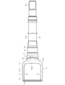
- the forged material 13 a ′ of the shaft member 13 a after forging is formed with enlarged diameter portions 61 and 62 at both ends of the shaft portion 60 and a recessed portion 61 d at the end portion of the enlarged diameter portion 61.
- the outer diameter of the shaft portion 60 is the same as the outer diameter of a billet (not shown) obtained by cutting the bar material.
- the base material 13a ' is made of a medium carbon steel containing 0.30 to 0.55% by weight of carbon such as S40C. As described above, the base material 13a 'is subjected to post-processing such as turning, spline processing, and grinding.
- the shaft member 13 a obtained by post-processing the raw material 13 a ′ has a joining end surface 50, a joining portion outer diameter surface 51, and a joining portion on a large diameter portion 61 a (see FIG. 3) of the enlarged diameter portion 61.
- An inner diameter surface 52 is formed, and the bearing mounting surface 14 and the retaining ring groove 15 are formed in the middle diameter portion 61 b of the enlarged diameter portion 61.
- a spline Sp and a seal surface 53 are formed in the enlarged diameter portion 62.
- FIGS. 5a and 5b The cup member 12a and its base material 12a 'are shown in FIGS. 5a and 5b.
- the cup member 12a is made of medium carbon steel containing 0.40 to 0.60% by weight of carbon such as S53C.
- FIG. 5a shows the base material 12a 'of the cup member 12a after ironing. This is an integrally molded product comprising a cylindrical portion 12a1 'and a bottom portion 12a2' having a track groove 30 and a cylindrical inner peripheral surface 42 formed on the inner periphery. The track groove 30 and the cylindrical inner peripheral surface 42 are finished surfaces by ironing. Convex portions 12a3 'are formed on the bottom 12a2' of the base material 12a '.
- FIG. 5b shows the cup member 12a after turning.
- a boot mounting groove 32 is formed on the outer periphery on the opening side of the cup member 12a, and a retaining ring groove 33 is formed on the inner periphery.
- the joining end surface 54 of the bottom portion 12a2 (convex portion 12a3) of the cup member 12a is turned in a ring-shaped manner, and the forged skin remains in the central portion in the radial direction. This shortens the turning time.
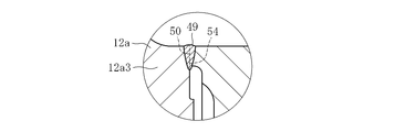
- the shaft member 13a includes a joining end surface 54 formed on the convex portion 12a3 of the bottom 12a2 of the cup member 12a, and a joining end surface 50 at the end of the shaft member 13a on the cup member 12a side.
- a joining end surface 54 formed on the convex portion 12a3 of the bottom 12a2 of the cup member 12a, and a joining end surface 50 at the end of the shaft member 13a on the cup member 12a side.
- the welded portion 49 is formed by a bead of a beam irradiated from the outside in the radial direction.
- the bearing mounting surface 14 can be processed in advance, and after welding Processing can be abolished. Further, since burrs do not appear in the weld due to electron beam welding, post-processing of the weld can be omitted, and the manufacturing cost can be reduced. Further, 100% inspection by ultrasonic flaw detection of the welded portion is possible.
- the present invention is not limited to this, and the present invention can be applied to an intermediate shaft of a drive shaft having a plurality of enlarged diameter portions, a power transmission shaft, and other shaft-shaped products.
- FIGS. 6 to 9 show a primary forging process in which a part of the plurality of enlarged diameter parts is formed in advance
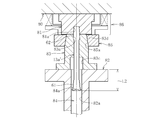
- FIGS. 10 to 12 show a secondary forging process in which the remaining enlarged diameter part is formed.
- the primary forging process consists of a first process and a second process.
- the main mold in the first step includes an upper base 70, a punch 71, a lower base 72, a die 73 and a knockout pin 74.
- a press facility an example in which a general-purpose screw press that is a mechanical press is applied will be described.
- the present invention is not limited to this, as long as it can be molded by operating a die using general-purpose press equipment or equipment that can operate in accordance with this, such as a connecting rod press as a mechanical press, a hydraulic press, etc.
- a non-mechanical press may be used.
- the punch 71 has a tapered molding surface 71a, and the punch 71 is fixedly attached to the upper base 70 that does not move in the vertical direction.
- the die 73 is formed with a two-stage cylindrical molding surface 73a and an inner diameter hole 73b that accommodates the billet B and restrains it in the radial direction, and is fixedly attached to the lower base 72 that is driven in the vertical direction.
- a guide hole 72a is formed in the lower base 72, and a knockout pin 74 as a work receiving member is slidably inserted.
- the amount of downward retreat of the knockout pin 74 in the lower base 72 is regulated by a stopper (not shown), and as shown in FIGS. 7 and 9, the advance when the lower base 72 advances upward.
- the position dimension L1 of the workpiece receiving surface 74a of the knockout out pin 74 at the end is guaranteed by the equipment or the mold size. Therefore, since the full length dimension of the shaped material after forging is stabilized, the machining allowance for post-processing can be reduced.
- the molded portion of billet B is heated to about 800 ° C. to 1000 ° C. Thereby, the normalizing process and the shot peening process after forging can be omitted, the productivity of the shaft member can be improved, and the manufacturing cost can be reduced.
- the heated billet B is carried into the inner diameter hole 73b of the die 73 by a loader (not shown), and the knockout pin 74 as a workpiece receiving member is Place on the workpiece receiving surface 74a. Since the gap between the outer diameter of the billet B and the inner diameter hole 73b of the die 73 is very small, the billet B can be restrained with high accuracy in the radial direction.
- the lower base 72 is driven and moves upward. Then, the billet B receives pressure from the punch 71 in a state where the guide portion 73 c of the die 73 is fitted into the guide portion 71 b of the punch 71 and the punch 71 and the die 73 are aligned.
- the knockout pin 74 is retracted downward due to the pressure applied by the punch 71. As described above, the amount of downward retreat of the knockout pin 74 in the lower base 72 is determined by a stopper (not shown).
- the billet B fills the cavity formed by the molding surface 71a of the punch 71 and the molding surface 73a of the die 73, and the enlarged diameter portion 61 ′ is molded as shown in FIG. Since the position dimension L1 of the workpiece receiving surface 74a of the knockout out pin 74 at the advance end when the lower base 72 advances upward is guaranteed, the overall length dimension of the forged material B 'is stabilized.
- the mold in the second step is different from the first step only in punching.
- the first step and the second step are performed, for example, with one press facility.
- the punch 75 in the second step has a molding surface 75a for molding the large diameter portion 61a and the concave portion 61d of the enlarged diameter portion 61 of the shaped member 13a 'shown in FIG.
- the punch 71 in the first step slides in the horizontal direction and the punch 75 in the second step moves in the horizontal direction. It slides and is placed at the position shown in FIG.
- the lower base 72 is driven and moves upward. Then, in the state where the guide portion 73 c of the die 73 is fitted into the guide portion 75 b of the punch 75 and the punch 75 and the die 73 are aligned with each other, the base material B ′ receives the pressing force of the punch 75.
- the knockout pin 74 is retracted downward by the pressure applied by the punch 75.
- the amount of downward retreat of the knockout pin 74 in the lower base 72 is determined by a stopper ( As shown in FIG. 9, the base material B ′ fills the molding surface 75a of the punch 75, and the base material B ′′ is obtained.
- the large diameter portion 61a and the concave portion 61d of the enlarged diameter portion 61 shown in FIG. 3 are formed, and together with the medium diameter portion 61b and the small diameter portion 61c formed in the first step, The forming of the enlarged diameter portion 61 is completed.
- the operation of the mold in the first step and the second step is performed continuously. Thereafter, the lower base 72 is retracted downward, and the base material B ′′ is discharged by the knockout pin 74.
- the main mold in the secondary forging process includes an upper base 80, a punch 81, a closing ring 85, a closing ring pressurizing mechanism 86, a lower base 82, a split die 83, and a knockout pin 84.
- the punch 81 has a tapered molding surface 81a, and the punch 81 is fixedly attached to an upper base 80 fixed in the vertical direction.
- a closing ring 85 is provided below the punch 81, and the closing ring 85 has a tapered inner diameter surface 85a.
- the closing ring 85 is attached to the upper base 80 via a closing ring pressurizing mechanism 86.
- the split die 83 has a structure that is split into two in the diameter direction. However, the number of divisions is not limited to this, and may be an appropriate number of divisions of three or more.
- the split die 83 is formed with a molding surface 83a, an inner diameter surface 83b that accommodates the shaft portion 60 of the base material B ′′ and restrains it radially, and a large diameter step portion 83c that accommodates the enlarged diameter portion 61.
- the split die 83 is attached to the lower base 82 so as to be relatively movable in the lateral direction, and the split die 83 can be opened and closed by an appropriate driving device (not shown) such as an air cylinder.
- a tapered outer diameter surface 83d that fits into the tapered inner diameter surface 85a of the closing ring 85 is formed on the upper portion.
- the lower base 82 is driven in the vertical direction.
- a guide hole 82a is formed in the lower base 82, and a knockout pin 84 as a work receiving member is slidably inserted.
- the amount of downward retreat of the knockout pin 84 in the lower base 82 is regulated by a stopper (not shown), and as shown in FIG. 12, the knockout at the forward end when the lower base 82 advances upward is shown.
- the position dimension L2 of the workpiece receiving surface 84a of the out pin 84 is guaranteed by the equipment or the mold dimensions. Therefore, since the full length dimension of the shaped material after forging is stabilized, the machining allowance for post-processing can be reduced.
- the operation of the secondary forging process will be described with reference to FIGS.
- the molded portion on the opposite side to the enlarged diameter portion 61 of the base material B ′′ formed in the primary forging process is heated to about 800 ° C. to 1000 ° C. as in the primary forging process.
- the lower base 72 is retracted downward, and the split die 83 is open.
- the workpiece B ′′ is gripped by a loader (not shown), and the workpiece of the knockout pin 84 is placed with the enlarged diameter portion 61 facing downward. It is placed on the receiving surface 84a. Since the split die 83 is in an open state, the enlarged diameter portion 61 of the base material B ′′ can be placed on the workpiece receiving surface 84a without interfering with the inner diameter surface 83b of the split die 83.
- the split die 83 is closed by an appropriate driving device (not shown) such as an air cylinder.
- an appropriate driving device such as an air cylinder.
- the mating surfaces 83e and 83e (see FIG. 10) of the two split dies 83 and 83 are in contact with each other, so that a minute line appears at the joint between the two molding surfaces 83a and 83a.
- the gap between the inner diameter formed by the two inner diameter surfaces 83b and 83b and the outer diameter of the shaft portion B is extremely small, the billet B" can be restrained with high accuracy in the radial direction. .
- the lower base 72 is driven and moves upward.
- the tapered outer diameter surface 83d of the divided die 83 is fitted to the tapered inner diameter surface 85a of the closing ring 85, and a force for closing the divided die 83 is applied by the closing ring 85 and the closing ring pressurizing mechanism 86. With the force applied, the lower base 72 continues to rise together with the closing ring 85 and the split die 83.
- the position dimension L2 (see FIG. 12) of the workpiece receiving surface 84a of the knockout out pin 84 at the forward end when the lower base 82 advances upward is guaranteed. Therefore, when the lower base 82 continues to rise, the knockout pin 84 in the lower base 82 is regulated by a stopper (not shown), and the upper end portion of the base material B ′′ is molded by the molding surface 81a of the punch 81. At the same time, molding is started by the molding surface 83a of the split die 83. Then, as shown in Fig. 12, when the lower base 82 reaches the upward advance end, the molding surface 81a of the punch 81 is reached. The material is filled in the cavity formed by the molding surface 83a of the split die 83, and the molding of the enlarged diameter portion 62 is completed.
- the divided die 83 is closed, and the outer diameter is applied by the closing ring 85 and the closing ring pressurizing mechanism 86.
- the mating surfaces 83e and 83e of the two divided dies 83 and 83 come into close contact with each other, so that the joint between the two molding surfaces 83a and 83a becomes a minute linear gap. Since this gap is extremely small, material flow into the gap can be suppressed during molding, and a minute linear indentation is generated in the remaining enlarged diameter portion 62 formed in the secondary forging process. For this reason, the removal process of the burr
- both end faces of the shaped material B ′′ are constrained by a die (punch 81, knockout pin 84) during molding, there is little deformation (bending, etc.) of the product (molded material 13a ′). Removal processing and correction processing in the post-process are unnecessary or can be reduced.
- the present invention is not limited to this, as long as it can be molded by operating a die using general-purpose press equipment or equipment that can operate in accordance with this, such as a connecting rod press as a mechanical press, a hydraulic press, etc.
- a non-mechanical press may be used.
- the punch 81 is attached to the upper base 80 and the split die 83 is attached to the lower base 82 is shown.
- the punch 81 is attached to the lower base 82 and the split die 83 is attached to the upper base 82.
- the shaft member 13a ′ having the two enlarged diameter portions 61 and 62 at both ends of the shaft portion 60 is exemplified, but the present invention is not limited to this, and the present invention is also applicable to a shaft member having three or more enlarged diameter portions. be able to.
- one enlarged portion can be formed in the primary forging step, and two enlarged portions can be formed in one step or two steps in the secondary forging step.
- the one enlarged diameter portion means a part of the enlarged diameter portion, and the two enlarged diameter portions mean the remaining enlarged diameter portion.
Landscapes
- Engineering & Computer Science (AREA)
- Mechanical Engineering (AREA)
- General Engineering & Computer Science (AREA)
- Forging (AREA)
Abstract
L'invention concerne un procédé consistant à forger un élément d'arbre (13a) d'un joint homocinétique (10, 20) comprenant une pluralité de sections à diamètre élargi (61, 62) sur une partie d'arbre (60). Dans le procédé, sur un matériau mis en forme (B') présentant la section à diamètre élargi (61) qui est une partie de la pluralité de sections à diamètre élargi (61, 62) et qui est moulée à l'avance, le reste de la section à diamètre élargi (62) est moulé. Le procédé est caractérisé en ce qu'il comprend, comme moule destiné à mouler le reste de la section à diamètre élargi (62): un poinçon (81); une filière extensible (83) qui présente une surface de moulage (83a) et qui reçoit la partie d'arbre (60) et la section à diamètre élargi (61) qui est une partie du matériau mis en forme (B"); et un élément de réception de pièce (84) supportant la force de mise sous pression du poinçon (81) et sur lequel est disposée la section à diamètre élargi (61) qui est la partie du matériau mis en forme (B"), après la disposition, sur l'élément de réception de pièce (84), du matériau mis en forme (B") présentant la section à diamètre élargi (61), qui est la partie moulée sur celui-ci, le matériau mis en forme (B") étant retenu radialement par la fermeture de la filière extensible (83), et, dans cet état, le matériau mis en forme (B") étant amené à remplir la surface de moulage (83a) de la filière extensible par la force de mise sous pression du poinçon (81), ce qui permet de mouler le reste de la section à diamètre élargi (62).
Priority Applications (3)
| Application Number | Priority Date | Filing Date | Title |
|---|---|---|---|
| CN201680040352.7A CN107848015B (zh) | 2015-07-15 | 2016-06-20 | 等速万向联轴器的轴构件的锻造方法 |
| EP16824217.0A EP3323526B1 (fr) | 2015-07-15 | 2016-06-20 | Procédé de forgeage d'élément d'arbre de joint homocinétique |
| US15/743,827 US10933462B2 (en) | 2015-07-15 | 2016-06-20 | Method for forging shaft member of constant velocity universal joint |
Applications Claiming Priority (2)
| Application Number | Priority Date | Filing Date | Title |
|---|---|---|---|
| JP2015-141234 | 2015-07-15 | ||
| JP2015141234A JP6588262B2 (ja) | 2015-07-15 | 2015-07-15 | 等速自在継手の軸部材の鍛造方法 |
Publications (1)
| Publication Number | Publication Date |
|---|---|
| WO2017010237A1 true WO2017010237A1 (fr) | 2017-01-19 |
Family
ID=57757840
Family Applications (1)
| Application Number | Title | Priority Date | Filing Date |
|---|---|---|---|
| PCT/JP2016/068240 Ceased WO2017010237A1 (fr) | 2015-07-15 | 2016-06-20 | Procédé de forgeage d'élément d'arbre de joint homocinétique |
Country Status (5)
| Country | Link |
|---|---|
| US (1) | US10933462B2 (fr) |
| EP (1) | EP3323526B1 (fr) |
| JP (1) | JP6588262B2 (fr) |
| CN (1) | CN107848015B (fr) |
| WO (1) | WO2017010237A1 (fr) |
Cited By (1)
| Publication number | Priority date | Publication date | Assignee | Title |
|---|---|---|---|---|
| CN110756723A (zh) * | 2019-11-22 | 2020-02-07 | 湖南高致精工机械有限公司 | 一种传动轴锻件成形工艺及锻造模 |
Families Citing this family (2)
| Publication number | Priority date | Publication date | Assignee | Title |
|---|---|---|---|---|
| JP7412099B2 (ja) * | 2019-07-05 | 2024-01-12 | Ntn株式会社 | 動力伝達機構及び車両 |
| CN114523272A (zh) * | 2022-02-11 | 2022-05-24 | 中信戴卡股份有限公司 | 一种铝合金传动轴制备方法 |
Citations (4)
| Publication number | Priority date | Publication date | Assignee | Title |
|---|---|---|---|---|
| JPS63106543U (fr) * | 1986-12-27 | 1988-07-09 | ||
| JPH11347683A (ja) * | 1998-06-09 | 1999-12-21 | Tokai Rika Co Ltd | 長軸、長軸製造方法及び長軸製造装置 |
| JP2002346683A (ja) * | 2001-05-22 | 2002-12-03 | Denso Corp | 鍛造装置および鍛造方法 |
| JP2015064101A (ja) * | 2013-08-29 | 2015-04-09 | Ntn株式会社 | 等速自在継手の外側継手部材の製造方法および外側継手部材 |
Family Cites Families (8)
| Publication number | Priority date | Publication date | Assignee | Title |
|---|---|---|---|---|
| JPS6137341A (ja) * | 1984-07-30 | 1986-02-22 | Toyota Motor Corp | 異形断面形状を有する閉塞鍛造用荒地素材の製造装置 |
| FR2602592B1 (fr) | 1986-08-06 | 1989-06-30 | Alain Baret | Utilisation du systeme enzymatique xanthine-oxydase en immuno-analyse, procedes de dosage correspondants et coffrets de reactifs necessaires pour la mise en oeuvre de ces procedes. |
| US5378205A (en) * | 1992-08-05 | 1995-01-03 | Gohl; Allen P. | Extruded metal chain pin |
| JP2000326046A (ja) * | 1999-05-20 | 2000-11-28 | Honda Motor Co Ltd | 軸状部品の成形方法及び成形装置 |
| JP3802285B2 (ja) | 1999-07-21 | 2006-07-26 | 株式会社神戸製鋼所 | アプセッターにおけるフランジ成形方法 |
| BRPI0704944A8 (pt) * | 2007-11-30 | 2017-08-15 | V & M Do Brasil S/A | Eixo forjado de tubo sem costura para veículos ferroviários e processo de fabricação de eixo forjado de tubo sem costura para veículos ferroviários |
| CN102554090A (zh) * | 2012-02-17 | 2012-07-11 | 四川新筑精坯锻造有限公司 | 工作夹片热挤压通孔的锻造方法 |
| JP2013215774A (ja) * | 2012-04-09 | 2013-10-24 | Ntn Corp | フランジ構造体およびフランジ構造体製造方法 |
-
2015
- 2015-07-15 JP JP2015141234A patent/JP6588262B2/ja active Active
-
2016
- 2016-06-20 CN CN201680040352.7A patent/CN107848015B/zh active Active
- 2016-06-20 WO PCT/JP2016/068240 patent/WO2017010237A1/fr not_active Ceased
- 2016-06-20 US US15/743,827 patent/US10933462B2/en active Active
- 2016-06-20 EP EP16824217.0A patent/EP3323526B1/fr active Active
Patent Citations (4)
| Publication number | Priority date | Publication date | Assignee | Title |
|---|---|---|---|---|
| JPS63106543U (fr) * | 1986-12-27 | 1988-07-09 | ||
| JPH11347683A (ja) * | 1998-06-09 | 1999-12-21 | Tokai Rika Co Ltd | 長軸、長軸製造方法及び長軸製造装置 |
| JP2002346683A (ja) * | 2001-05-22 | 2002-12-03 | Denso Corp | 鍛造装置および鍛造方法 |
| JP2015064101A (ja) * | 2013-08-29 | 2015-04-09 | Ntn株式会社 | 等速自在継手の外側継手部材の製造方法および外側継手部材 |
Non-Patent Citations (1)
| Title |
|---|
| See also references of EP3323526A4 * |
Cited By (1)
| Publication number | Priority date | Publication date | Assignee | Title |
|---|---|---|---|---|
| CN110756723A (zh) * | 2019-11-22 | 2020-02-07 | 湖南高致精工机械有限公司 | 一种传动轴锻件成形工艺及锻造模 |
Also Published As
| Publication number | Publication date |
|---|---|
| CN107848015B (zh) | 2020-04-28 |
| CN107848015A (zh) | 2018-03-27 |
| JP6588262B2 (ja) | 2019-10-09 |
| EP3323526A4 (fr) | 2019-03-13 |
| US10933462B2 (en) | 2021-03-02 |
| EP3323526A1 (fr) | 2018-05-23 |
| EP3323526B1 (fr) | 2021-09-29 |
| US20180200782A1 (en) | 2018-07-19 |
| JP2017019008A (ja) | 2017-01-26 |
Similar Documents
| Publication | Publication Date | Title |
|---|---|---|
| CN107249768B (zh) | 制造管件的方法和其中使用的机器 | |
| US8127585B2 (en) | Process for manufacturing outer ring member for constant-velocity joint | |
| EP3040570B1 (fr) | Procédé de production d'élément de joint externe pour joint universel homocinétique et élément de joint externe | |
| US20140053623A1 (en) | Hot extrusion method for producing a metal part, extrusion tool for implementation it and landing gear rod thus produced | |
| KR102211190B1 (ko) | 등속 볼 조인트용 케이지 제조 방법 | |
| JP6588262B2 (ja) | 等速自在継手の軸部材の鍛造方法 | |
| US11759846B2 (en) | Method for producing a polygonal shaft | |
| US10514070B2 (en) | Method for manufacturing outer joint member for constant velocity universal joint, shaft member and outer joint member | |
| JP6338912B2 (ja) | 突合せ溶接用芯出し方法及び装置 | |
| EP3309420B1 (fr) | Élément de joint externe d'un joint universel homocinétique | |
| JP2008194734A (ja) | 等速自在継手用外方部材の製造方法、およびその製造装置 | |
| EP3159566B1 (fr) | Procédé de fabrication d'un élément de joint externe d'un joint universel homocinétique et élément de joint externe | |
| CN106662160A (zh) | 等速万向联轴器的外侧联轴器构件及其制造方法 | |
| US20080120846A1 (en) | Apparatus And Method For Manufacturing Outer Race Member For Constant Velocity Joint And Intermediate Molded Body Of The Outer Race Member | |
| JP5912694B2 (ja) | 等速自在継手用外側継手部材の製造方法 | |
| EP3156676A1 (fr) | Procédé de fabrication d'un élément de joint extérieur pour joint universel homocinétique et élément de joint extérieur |
Legal Events
| Date | Code | Title | Description |
|---|---|---|---|
| 121 | Ep: the epo has been informed by wipo that ep was designated in this application |
Ref document number: 16824217 Country of ref document: EP Kind code of ref document: A1 |
|
| WWE | Wipo information: entry into national phase |
Ref document number: 15743827 Country of ref document: US |
|
| NENP | Non-entry into the national phase |
Ref country code: DE |
|
| WWE | Wipo information: entry into national phase |
Ref document number: 2016824217 Country of ref document: EP |