WO2017010331A1 - 車両用視認装置 - Google Patents
車両用視認装置 Download PDFInfo
- Publication number
- WO2017010331A1 WO2017010331A1 PCT/JP2016/069795 JP2016069795W WO2017010331A1 WO 2017010331 A1 WO2017010331 A1 WO 2017010331A1 JP 2016069795 W JP2016069795 W JP 2016069795W WO 2017010331 A1 WO2017010331 A1 WO 2017010331A1
- Authority
- WO
- WIPO (PCT)
- Prior art keywords
- visual recognition
- vehicle
- wall
- visual
- support
- Prior art date
- Legal status (The legal status is an assumption and is not a legal conclusion. Google has not performed a legal analysis and makes no representation as to the accuracy of the status listed.)
- Ceased
Links
Images

Classifications
-
- B—PERFORMING OPERATIONS; TRANSPORTING
- B60—VEHICLES IN GENERAL
- B60R—VEHICLES, VEHICLE FITTINGS, OR VEHICLE PARTS, NOT OTHERWISE PROVIDED FOR
- B60R1/00—Optical viewing arrangements; Real-time viewing arrangements for drivers or passengers using optical image capturing systems, e.g. cameras or video systems specially adapted for use in or on vehicles
- B60R1/02—Rear-view mirror arrangements
- B60R1/06—Rear-view mirror arrangements mounted on vehicle exterior
- B60R1/062—Rear-view mirror arrangements mounted on vehicle exterior with remote control for adjusting position
- B60R1/07—Rear-view mirror arrangements mounted on vehicle exterior with remote control for adjusting position by electrically powered actuators
- B60R1/072—Rear-view mirror arrangements mounted on vehicle exterior with remote control for adjusting position by electrically powered actuators for adjusting the mirror relative to its housing
Definitions
- the present invention relates to a vehicle visual recognition device in which visual recognition means assists visual recognition of a vehicle occupant.
- the motor holder of the mirror surface angle adjustment unit is fixed to the partition wall of the housing body, and the mirror is assembled to the pivot plate of the mirror surface angle adjustment unit.
- the housing main body accommodates the mirror angle adjustment unit and the mirror.
- the motor holder covers the side opposite to the motor mirror, and the mirror side of the motor is covered with the inner member.
- the motor holder slides the pivot plate and the mirror on the outer peripheral side of the motor mirror. Supports movable.
- An object of the present invention is to obtain a vehicular visual recognition device that can improve the assembling property in consideration of the above facts.
- the visual recognition device for a vehicle includes visual recognition means for assisting visual recognition of a vehicle occupant, an operation mechanism in which the visual recognition means is tilted by being operated, and an outer peripheral side of the visual recognition means of the operation mechanism. And a support body for slidably supporting the visual recognition means, and a support body provided with a covering portion for covering the visual recognition means side of the operating mechanism.
- the visual device for a vehicle includes visual means for assisting visual recognition of a vehicle occupant, an operating mechanism in which the visual means is tilted by being actuated, and an outer peripheral side of the visual means of the operating mechanism. And a support body that slidably supports the visual recognition means and that allows the operating mechanism to be assembled from the side opposite to the visual recognition means.
- the visual device for a vehicle according to a third aspect of the present invention is the visual device for a vehicle according to the first aspect or the second aspect of the present invention, wherein the visual device for the vehicle is assembled to the support body from the opposite side to the visual means. And a storage mechanism for storing the visual recognition means.
- the visual device for a vehicle according to a fourth aspect of the present invention is the visual device for a vehicle according to any one of the first to third aspects of the present invention, and is assembled to the support body from the side opposite to the visual means.
- a reinforcing body for reinforcing the supporting body is provided.
- a vehicle visual recognition device is the vehicle visual recognition device according to any one of the first to fourth aspects of the present invention, wherein the visual recognition device is provided on the support, and the visual recognition device is provided at a center side of the visual recognition means.
- a central support is provided for slidably supporting the means.
- the visual device for a vehicle according to a sixth aspect of the present invention is the visual device for a vehicle according to any one of the first to fifth aspects of the present invention, and is provided integrally with an accommodating portion that accommodates the visual recognition means.
- a central support portion is provided on the central side of the means for slidably supporting the visual recognition means.
- the visual device for a vehicle according to a seventh aspect of the present invention is the visual device for a vehicle according to the fifth aspect or the sixth aspect of the present invention, wherein the visual recognition of the sliding surface of the support portion with the visual recognition means and the central support portion.
- the sliding surface with the means is a spherical surface having the same center.
- the vehicular visual recognition device includes visual recognition means for assisting visual recognition of an occupant of the vehicle, an actuation mechanism that tilts the visual recognition means when actuated, and a housing portion that accommodates the visual recognition means. And a container provided with a covering portion that covers the viewing means side of the operating mechanism.
- a vehicular visual recognition device that accommodates visual recognition means for assisting visual recognition of a vehicle occupant, an actuation mechanism that tilts the visual recognition means when actuated, and the visual recognition means. And a container that enables the mechanism to be assembled from the side opposite to the visual recognition means.
- the visual device for a vehicle according to a tenth aspect of the present invention is the visual device for a vehicle according to the eighth aspect or the ninth aspect of the present invention, wherein the vehicle is assembled and operated from the side opposite to the visual means. And a storage mechanism for storing the visual recognition means.
- the vehicular visual recognition device is the vehicle visual recognition device according to any one of the eighth to tenth aspects of the present invention, and is assembled to the container from the side opposite to the visual recognition means.
- a reinforcing body for reinforcing the container is provided.
- the visual recognition means assists visual recognition of the vehicle occupant. Furthermore, the visualizing means is tilted by operating the operating mechanism.
- the support is provided with a support portion and a covering portion, and the support portion slidably supports the visual recognition means on the outer peripheral side of the visual recognition means of the operation mechanism, and the cover portion covers the visual recognition means side of the operation mechanism. To do. For this reason, the number of parts can be reduced and the assemblability can be improved.
- the visual recognition means assists the visual observation of the vehicle occupant. Furthermore, the visualizing means is tilted by operating the operating mechanism. Further, the support body slidably supports the visual recognition means on the outer peripheral side of the visual recognition means of the operation mechanism.
- the support allows the operating mechanism to be assembled from the side opposite to the visual means. For this reason, assembly property can be improved.
- the visual recognition means is stored by operating the storage mechanism.
- the storage mechanism is assembled to the support from the side opposite to the visual means. For this reason, assembly property can be improved further.
- the reinforcement body reinforces the support body.
- the reinforcing body is assembled to the support body from the side opposite to the visual means. For this reason, assembly property can be improved further.
- the central support portion slidably supports the visual recognition means on the central side of the visual recognition means.
- the support is provided with a central support. For this reason, the number of parts can be reduced and the assemblability can be further improved.
- the accommodating portion accommodates the visual recognition means, and the central support portion slidably supports the visual recognition means on the center side of the visual recognition means.
- the central support part is provided integrally with the accommodating part. For this reason, the number of parts can be reduced and the assemblability can be further improved.
- the sliding surface with the visual recognition means of the support portion and the sliding surface with the visual recognition means of the central support portion are formed into a spherical surface having the same center. For this reason, tilting of the visual recognition means can be stabilized.
- the visual recognition means assists the visual recognition of the vehicle occupant. Furthermore, the visualizing means is tilted by operating the operating mechanism.
- the accommodating portion and the covering portion are provided in the accommodating body, and the accommodating portion accommodates the visual recognition means, and the covering portion covers the visual recognition means side of the operating mechanism. For this reason, the number of parts can be reduced and the assemblability can be improved.
- the container accommodates the visual recognition means, and the visual recognition means assists visual recognition of the vehicle occupant. Furthermore, the visualizing means is tilted by operating the operating mechanism.
- the container allows the operating mechanism to be assembled from the side opposite to the visual means. For this reason, assembly property can be improved.
- the visual recognition means is stored by operating the storage mechanism.
- the storage mechanism is assembled to the container from the side opposite to the visual means. For this reason, assembly property can be improved further.
- the reinforcing body reinforces the container.
- the reinforcing body is assembled to the container from the side opposite to the visual means. For this reason, assembly property can be improved further.
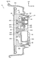
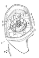
- FIG. 1 is an exploded perspective view of a vehicle door mirror device according to an embodiment of the present invention, viewed from the front side of the vehicle and from the inner side in the vehicle width direction. It is sectional drawing seen from the vehicle width direction outer side which shows the principal part of the door mirror apparatus for vehicles which concerns on embodiment of this invention. It is the perspective view seen from the vehicle rear side and the vehicle width direction inner side which shows the visor body of the vehicle door mirror apparatus which concerns on embodiment of this invention.
- FIG. 1 shows an exploded perspective view of a vehicle door mirror device 10 as a vehicle visual recognition device according to an embodiment of the present invention as seen from the front side of the vehicle and the inner side in the vehicle width direction (left side of the vehicle).
- the main part of the vehicle door mirror device 10 is shown in a cross-sectional view as seen from the vehicle width direction outer side (vehicle right side).
- the front side of the vehicle is indicated by an arrow FR
- the outer side in the vehicle width direction is indicated by an arrow OUT
- the upper side is indicated by an arrow UP.
- the vehicle door mirror device 10 is supported on the outside of a vehicle door (front side door, vehicle body side).
- the vehicle door mirror device 10 includes a storage mechanism 12.
- the storage mechanism 12 is provided with a stand 12A as a support member, and the vehicle door mirror device 10 is supported by the door by the stand 12A being supported by the vehicle front side end of the middle portion in the vertical direction of the door. .
- a rotating body 12B is supported on the stand 12A, and the rotating mechanism 12B is rotated in the vertical direction with respect to the stand 12A when the storage mechanism 12 is electrically operated.
- the rotating body 12B is electrically connected to a control device (not shown) on the vehicle body side, and the storage mechanism 12 is electrically operated under the control of the control device.
- the rotating body 12B of the storage mechanism 12 supports a resin visor 14 as an outer peripheral body.
- the visor 14 is provided with a visor body 16 as a support body and a container.
- a first screw 18A and a second screw 18B as assembly members are provided on the vehicle front side of the visor body 16 in the vehicle width direction inner end portion.
- the rotating body 12B is fixed by fastening or the like.
- a curved plate-like visor cover 20 as a covering member is assembled on the vehicle front side of the visor body 16 through the following reinforcement 24.
- the visor cover 20 has an outer periphery fitted to the outer periphery of the visor body 16, Sixteen vehicle front sides are covered.
- the visor cover 20 is provided with an upper cover 20A on the upper side and a lower cover 20B on the lower side.
- the visor cover 20 is configured by combining the upper cover 20A and the lower cover 20B.
- the visor body 16 is provided with a substantially rectangular parallelepiped box-shaped housing wall 16A as a housing portion, and the inside of the housing wall 16A is open to the rear side of the vehicle.
- a support wall 16B (case lower portion) as a support portion is integrally provided on the vehicle front side wall (bottom wall) of the accommodation wall 16A, and the support wall 16B includes a vehicle front side of the vehicle front side wall of the accommodation wall 16A and a vehicle. It protrudes to the rear side.
- the support wall 16B has a substantially cylindrical shape, and the central axis of the support wall 16B is disposed in parallel with the vehicle longitudinal direction.
- the support wall 16B has a spherical wall shape, and the inner diameter of the support wall 16B is gradually increased toward the rear of the vehicle.
- a plurality of long plate-like support protrusions 16G as support portions are integrally provided on the inner peripheral surface of the support wall 16B, and the support protrusions 16G protrude from the inner peripheral surface of the support wall 16B toward the center.
- the protruding end surface 16H sliding surface
- the support protrusions 16G are arranged at a plurality (three or more) at equal intervals in the circumferential direction of the support wall 16B, and the support protrusions 16G are arranged at a plurality of (this embodiment) in the central axis direction (vehicle longitudinal direction) of the support wall 16B.
- the plurality of support protrusions 16G in the central axis direction of the support wall 16B are partially overlapped with each other in the central axis direction of the support wall 16B, and the support protrusions 16G are disposed in the whole in the central axis direction of the support wall 16B. Has been.
- a container-like covering wall 16C (case upper portion) as a covering portion is provided in the supporting wall 16B, and the entire circumference of the vehicle front side end of the covering wall 16C is the entire circumference of the vehicle front side end of the support wall 16B. It is united with.
- a flat connecting wall 16D is integrally provided between the vehicle front side end of the covering wall 16C and the vehicle front side end of the supporting wall 16B. The connecting wall 16D is connected to the vehicle front side end of the covering wall 16C and the supporting wall. In the portion where the vehicle front end of 16B is not directly integrated, the vehicle front end of the covering wall 16C and the vehicle front end of the support wall 16B are connected.
- the inside of the covering wall 16C is opened to the vehicle front side of the support wall 16B, whereby the inside of the covering wall 16C is opened to the vehicle front side of the housing wall 16A.
- the connecting wall 16D is integrally provided with a predetermined number (four in this embodiment) of rectangular plate-like limiting plates 16E as limiting portions, and the limiting plate 16E protrudes from the connecting wall 16D to the vehicle front side. Yes.
- the predetermined number of restriction plates 16E are arranged at substantially equal intervals in the circumferential direction of the support wall 16B, and the restriction plates 16E are arranged so as to intersect with the radial direction of the support wall 16B.
- a cylindrical fitting tube 16F as a fitting portion is integrally provided on the outer peripheral surface of the support wall 16B in the middle portion in the vehicle front-rear direction, and the fitting tube 16F protrudes from the support wall 16B to the vehicle front side. In addition, it is arranged coaxially with the support wall 16B.
- a substantially cylindrical holding cylinder 22 as a central support part (holding part) is integrally provided on the vehicle rear side wall (bottom wall) of the covering wall 16C, and the holding cylinder 22 is a vehicle rear side wall of the covering wall 16C. Are projected on the vehicle front side and the vehicle rear side, and are arranged coaxially with the support wall 16B.
- a substantially spherical holding ball 22A is provided at the vehicle rear side end portion of the holding cylinder 22, and the circumferential surface of the vehicle front side portion of the holding ball 22A is a spherical holding surface 22B (sliding surface). The center is coincident with the center of the support wall 16B.
- a substantially resin-made long plate-like reinforcement 24 is provided as a reinforcement, and an intermediate portion in the vehicle width direction of the reinforcement 24 is The first screw 18A and the second screw 18B are fastened to the visor body 16 together with the rotating body 12B.
- a pair of triangular plate-like assembly plates 24B as an assembly portion are integrally provided on the outer side of the reinforcement 24 in the vehicle width direction, and the pair of assembly plates 24B are respectively connected to the upper side of the reinforcement 24 and the vehicle. It protrudes outward in the width direction.
- the outer portion in the vehicle width direction of the reinforcement 24 is fixed to the visor body 16 by fastening the third screw 18C and the fourth screw 18D as the assembly members in the pair of assembly plates 24B.
- the inner end in the vehicle width direction is fixed to the rotating body 12B by fastening the fifth screw 18E as an assembly member.
- the reinforcement 24 is higher in rigidity than the visor body 16, and the reinforcement 24 reinforces the visor body 16 and the rotating body 12B. Further, the visor cover 20 (lower cover 20B) of the visor 14 is fixed to the reinforcement 24 by fastening of the sixth screw 18F as a fixing member. As a result, the visor cover 20 is interposed via the reinforcement 24 as described above. It is assembled to the visor body 16.
- the reinforcement 24 is provided with an electric circuit (not shown), and the electric circuit is electrically connected to the control device.
- a disc-shaped bottom wall portion 24A as a closing portion is provided on the outer side in the vehicle width direction of the reinforcement 24, and an insertion portion is provided on the entire outer periphery of the vehicle rear side surface of the bottom wall portion 24A.
- a recess 26 having a rectangular cross section is formed.
- the bottom wall portion 24A is fitted into the fitting cylinder 16F of the visor body 16, and the vehicle front side end of the support wall 16B of the visor body 16 is inserted into the concave portion 26.
- the outer peripheral surface of the support wall 16B is fitted. Accordingly, the bottom wall portion 24A covers and closes the support wall 16B of the visor body 16 and the vehicle front side of the covering wall 16C.
- the bottom wall portion 24A is formed with a predetermined number (four in the present embodiment) of rectangular limiting holes 24C as a limited portion, and the predetermined number of limiting holes 24C is the circumferential direction of the bottom wall portion 24A. Are arranged at substantially equal intervals, and are arranged so as to intersect each other in the radial direction of the bottom wall portion 24A.
- the restriction plate 16E of the visor body 16 is inserted (fitted) into the restriction hole 24C, and thereby the movement of the bottom wall portion 24A in the circumferential direction and the radial direction with respect to the visor body 16 is restricted.
- a substantially cylindrical insertion post 24D as an insertion part is integrally provided at the center of the bottom wall part 24A, and the insertion post 24D protrudes from the bottom wall part 24A to the vehicle rear side, It is arranged coaxially with the portion 24A.
- the distal end portion of the insertion post 24D has a reduced diameter, and the front end portion of the insertion post 24D is inserted into the holding cylinder 22 of the visor body 16 from the front side of the vehicle.
- a cylindrical support tube 24E is integrally provided on the upper portion of the bottom wall portion 24A and on the outer side in the vehicle width direction on the inner side in the radial direction of the bottom wall portion 24A of the assembly plate 24B.
- the bottom wall portion 24A and the central axis line are arranged in parallel while projecting from the portion 24A to the vehicle rear side.
- a mirror surface adjustment mechanism 28 as an operation mechanism is held between the covering wall 16C of the visor body 16 and the bottom wall portion 24A of the reinforcement 24.
- the mirror surface adjustment mechanism 28 is provided with a pair of motors 30 as driving means, and the main body 30A of the motor 30 is held in a state of being sandwiched between the covering wall 16C and the bottom wall 24A.
- An output shaft 30B extends from the main body 30A, and a worm 32 as an output member is fixed to the output shaft 30B.
- the electric circuit of the reinforcement 24 is electrically connected to the main body 30A, and the mirror 30 is electrically operated by driving the motor 30 under the control of the control device.
- the mirror surface adjustment mechanism 28 is provided with a pair of resin-made substantially cylindrical wheel drives 34 as a transmission member, and the wheel drive 34 is fitted in the support cylinder 24E of the bottom wall portion 24A at the vehicle front side portion. In this state, it is sandwiched between the covering wall 16C and the bottom wall portion 24A, and is held rotatably around the axis.
- a worm wheel 34A is coaxially formed in an intermediate portion in the axial direction (vehicle longitudinal direction), and the worm wheel 34A is engaged (engaged) with the worm 32 of the motor 30. Yes. Therefore, when the motor 30 is driven and the worm 32 is rotated, the worm wheel 34A is rotated and the wheel drive 34 is rotated.
- a predetermined number (four in this embodiment) of engaging claws 34B as engaging portions are formed on the inner peripheral portion of the wheel drive 34 on the vehicle rear side of the worm wheel 34A.
- the wheel drives 34 are arranged at equal intervals in the circumferential direction.
- the meshing claw 34 ⁇ / b> B extends to the rear side of the vehicle and has elasticity, and the front end (vehicle rear side end) of the meshing claw 34 ⁇ / b> B protrudes radially inward of the wheel drive 34.
- a substantially cylindrical rod drive 36 as a moving member is coaxially inserted, and the rod drive 36 projects from the covering wall 16C to the rear side of the vehicle.
- One rod drive 36 is disposed above (or may be below) the central axis of the support wall 16B of the visor body 16, and the other rod drive 36 is located outward (in the vehicle width direction) of the central axis of the support wall 16B. (It may be inward in the width direction).
- the portion other than the tip (vehicle rear side end) of the rod drive 36 is a screw 36A, and the tip of the meshing claw 34B of the wheel drive 34 is meshed (engaged) with the screw 36A.
- the tip of the rod drive 36 is substantially spherical.
- a mirror body 38 as a visual recognition means is accommodated in the accommodation wall 16A of the visor body 16, and the entire circumference of the mirror body 38 and the vehicle front side are covered with the accommodation wall 16A.
- a substantially rectangular plate-like mirror 40 as a visual recognition part is provided on the rear side portion of the mirror body 38, and the surface of the mirror 40 is exposed to the rear side of the visor body 16.
- the mirror surface 40A (the surface of the reflective layer on the back side) of the mirror 40 is directed to the rear side of the vehicle, and the mirror 40 assists the vehicle occupant (especially the driver) to see the rear side of the vehicle.
- the mirror body 38 is provided with a resin-made substantially rectangular plate-like mirror holder 42 on the front side of the vehicle as a sliding body, and the mirror holder 42 is fixed (held) on the entire circumference of the mirror 40. In addition, the front side (back side) of the mirror 40 is covered.
- the mirror holder 42 is formed with a substantially cylindrical mounting wall 42A as a mounting portion on the vehicle front side of the center position (center of gravity position) of the mirror 40.
- the mounting wall 42A is coaxial with the support wall 16B of the visor body 16. Is placed on top.
- the mounting wall 42A has a substantially spherical wall shape, and the inner diameter of the mounting wall 42A is gradually increased toward the rear of the vehicle.
- a holding ball 22A of the holding cylinder 22 of the visor body 16 is fitted into the mounting wall 42A, whereby the mounting wall 42A is tiltably and slidably held on the holding surface 22B of the holding ball 22A.
- a substantially cylindrical sliding wall 42B as a sliding portion is integrally provided on the front side of the mirror holder 42 in the vehicle, and the sliding wall 42B is disposed coaxially with the support wall 16B of the visor body 16.
- the sliding wall 42B has a spherical wall shape, and the outer diameter of the sliding wall 42B is gradually increased toward the rear of the vehicle.
- the outer peripheral surface of the sliding wall 42B is in contact with the projecting end surface 16H of the support protrusion 16G on the support wall 16B, and the sliding wall 42B is tiltably and slidably supported by the projecting end surface 16H of the support projection 16G. ing.
- the mirror holder 42 is formed with a pair of substantially cylindrical rotating walls 42C as rotating portions on the radially inner side of the sliding wall 42B.
- One rotating wall 42C is a support wall 16B of the visor body 16.
- the other rotating wall 42C is disposed outward in the vehicle width direction (may be inward in the vehicle width direction) of the central axis of the support wall 16B.
- the rotating wall 42C is arranged in parallel with the central axis of the support wall 16B of the visor body 16 and has a substantially spherical wall shape.
- the inner diameter of the rotating wall 42C is determined from both ends in the vehicle front-rear direction. The size is gradually increased toward the center in the longitudinal direction of the vehicle.
- the tip end portion of the rod drive 36 in the mirror surface adjusting mechanism 28 is fitted and held.
- the rotating wall 42C is allowed to rotate with respect to the tip end portion of the rod drive 36, and the rod
- the rotation around the axis of the drive 36 is restricted. Therefore, as described above, when the wheel drive 34 (including the engagement claw 34B) is rotated in the mirror surface adjustment mechanism 28, the engagement position of the engagement claw 34B tip to the screw 36A of the rod drive 36 is displaced, The rod drive 36 is moved (slid) in the vehicle front-rear direction (axial direction).
- the storage mechanism 12 is electrically operated, whereby the rotating body 12B is rotated with respect to the stand 12A, and the mirror body 38 (visor 14 ( The visor body 16 and the visor cover 20), the reinforcement 24, and the mirror surface adjustment mechanism 28) are rotated.
- the mirror body 38 is stored by rotating the mirror body 38 to the vehicle rear side and the vehicle width direction inner side.
- the mirror body 38 is raised (deployed and returned) by rotating the mirror body 38 toward the vehicle front side and the vehicle width direction outside.
- the motor 30 is driven and the worm 32 is rotated, whereby the wheel drive 34 is rotated and the rod drive 36 is moved in the longitudinal direction of the vehicle.
- the mirror body 38 (mirror 40 and mirror holder 42) is tilted in at least one of the vertical direction and the vehicle width direction by the rod drive 36, so that the mirror surface 40A angle of the mirror 40 (viewing of the occupant assisted by the mirror 40) Direction) is adjusted in at least one of the vertical direction and the vehicle width direction.
- the mounting wall 42A of the mirror body 38 is held (supported) while being slid on the holding surface 22B of the holding ball 22A of the holding cylinder 22 of the visor body 16, and the mirror body 38
- the 38 sliding walls 42B are supported while being slid on the projecting end face 16H of the support projection 16G on the support wall 16B of the visor body 16.
- the visor body 16 is moved from the vehicle front side with respect to the mirror body 38, and the mirror body 38 is accommodated in the accommodating wall 16A of the visor body 16. At this time, the holding ball 22A of the visor body 16 is inserted into the mounting wall 42A of the mirror holder 42 from the front side of the vehicle.
- the storage mechanism 12 is assembled (arranged) to the visor body 16 from the front side of the vehicle.
- the mirror surface adjusting mechanism 28 (motor 30, worm 32, wheel drive 34 and rod drive 36) is assembled (arranged) on the covering wall 16C of the visor body 16 from the front side of the vehicle. At this time, the tip of the rod drive 36 is fitted into the rotating wall 42C of the mirror holder 42 from the front side of the vehicle.
- the reinforcement 24 is assembled to the visor body 16 and the rotating body 12B from the front side of the vehicle by the first screw 18A, the second screw 18B, the third screw 18C, the fourth screw 18D, and the fifth screw 18E.
- the visor cover 20 (upper cover 20A and lower cover 20B) is assembled to the visor body 16 and reinforcement 24 from the front side of the vehicle with the sixth screw 18F.
- the inside of the covering wall 16C in the support wall 16B is opened on the front side of the visor body 16 (the side opposite to the mirror body 38), and the reinforcement 24 is assembled on the front side of the visor body 16 in the vehicle.
- the bottom wall portion 24A of 24 covers the vehicle front side of the mirror surface adjustment mechanism 28 in the covering wall 16C. Therefore, the mirror surface adjustment mechanism 28 can be assembled from the front side of the visor body 16 into the covering wall 16C (inside the support wall 16B) without the reinforcement 24 being assembled to the front side of the visor body 16.
- the mirror surface adjustment mechanism 28 can also be assembled to the visor body 16 from the side where the visor cover 20 is assembled to the visor body 16 (the vehicle front side). Therefore, unlike the case where the mirror surface adjustment mechanism 28 is assembled to the visor body 16 from the rear side of the vehicle (the mirror body 38 side), the number of steps for assembling the vehicle door mirror device 10 can be reduced and the assembly line of the vehicle door mirror device 10 can be reduced. Can be simplified, the assembly can be improved, and the cost can be reduced. Moreover, the visor cover 20 can be prevented from being damaged when the vehicle door mirror device 10 is assembled, and the defect rate of the vehicle door mirror device 10 can be reduced.
- the storage mechanism 12 and the reinforcement 24 can be assembled to the visor body 16 from the side (the vehicle front side) where the mirror surface adjustment mechanism 28 and the visor cover 20 are assembled to the visor body 16. Therefore, unlike the case where at least one of the storage mechanism 12 and the reinforcement 24 is assembled to the visor body 16 from the rear side of the vehicle, the number of assembling steps for the vehicle door mirror device 10 can still be reduced and the assembly of the vehicle door mirror device 10 can be reduced.
- the attachment line can be simplified, the assemblability can be improved, and the cost can be reduced.
- the visor cover 20 can be prevented from being damaged when the vehicle door mirror device 10 is assembled, and the defect rate of the vehicle door mirror device 10 can be reduced.
- the visor body 16 is provided with a support wall 16B (a portion that slidably supports the sliding wall 42B of the mirror body 38) and a covering wall 16C (a portion that covers the rear side of the mirror surface adjusting mechanism 28). For this reason, the number of parts can be reduced, the assembling property can be further improved, and the cost can be further reduced. Furthermore, since the covering wall 16C supports the mirror body 38 via the mirror surface adjustment mechanism 28 (the wheel drive 34 and the rod drive 36), it is possible to suppress the positional deviation between the sliding wall 42B and the support wall 16B of the mirror body 38, When the mirror surface adjusting mechanism 28 is operated, the sliding resistance between the sliding wall 42B and the support wall 16B can be stabilized, and the tilting of the mirror body 38 can be stabilized.
- the covering wall 16C and the supporting wall 16B are integrated, foreign matter (for example, water) enters the covering wall 16C from the rear side of the visor body 16 through the housing wall 16A and the supporting wall 16B. This can be suppressed, and foreign matter can be prevented from entering the mirror surface adjustment mechanism 28 (particularly the motor 30).
- foreign matter for example, water
- the visor body 16 is provided with a support wall 16B (a portion that slidably supports the sliding wall 42B of the mirror body 38) and a holding cylinder 22 (a portion that slidably supports the mounting wall 42A of the mirror body 38). ing. For this reason, the number of parts can be reduced, the assembling property can be further improved, and the cost can be further reduced.
- the support wall 16B supports the sliding wall 42B of the mirror body 38 and the holding cylinder 22 supports the mounting wall 42A of the mirror body 38
- the displacement between the sliding wall 42B and the supporting wall 16B and the mounting wall can be suppressed, and the sliding resistance between the sliding wall 42B and the support wall 16B and the sliding resistance between the mounting wall 42A and the holding cylinder 22 when the mirror surface adjustment mechanism 28 is operated. Can be stabilized, and the tilt of the mirror body 38 can be further stabilized.
- the visor body 16 is provided with an accommodation wall 16A (a part for accommodating the mirror body 38) and a holding cylinder 22 (a part for slidably supporting the mounting wall 42A of the mirror body 38). For this reason, the number of parts can be reduced, the assembling property can be further improved, and the cost can be further reduced. Moreover, since the holding cylinder 22 supports the mounting wall 42A of the mirror body 38, it is possible to suppress the positional deviation between the housing wall 16A and the mirror body 38, and to stabilize the housing position of the mirror body 38 in the housing wall 16A. Can do.
- the holding surface 22B of the holding ball 22A of the visor body 16 on which the mounting wall 42A of the mirror body 38 slides is the same as the protruding end face 16H of the support protrusion 16G of the visor body 16 on which the sliding wall 42B of the mirror body 38 slides. It has a central spherical surface. For this reason, when the mirror surface adjustment mechanism 28 is operated, the sliding resistance between the sliding wall 42B and the support wall 16B and the sliding resistance between the mounting wall 42A and the holding cylinder 22 can be effectively stabilized. The tilting of the mirror body 38 can be stabilized effectively.
- the visor body 16 is provided with an accommodation wall 16A (a part for accommodating the mirror body 38) and a covering wall 16C (a part for covering the vehicle rear side of the mirror surface adjusting mechanism 28). For this reason, the number of parts can be reduced, the assembling property can be further improved, and the cost can be further reduced. Further, since the covering wall 16C supports the mirror body 38 via the mirror surface adjustment mechanism 28 (the wheel drive 34 and the rod drive 36), it is possible to suppress the positional deviation between the housing wall 16A and the mirror body 38, and into the housing wall 16A. The accommodation position of the mirror body 38 can be stabilized.
- the covering wall 16C is integrated with the receiving wall 16A via the support wall 16B, foreign matter (for example, inside the covering wall 16C from the rear side of the visor body 16 through the receiving wall 16A and the supporting wall 16B) Water) can be prevented from entering, and foreign matter can be prevented from entering the mirror surface adjustment mechanism 28 (particularly the motor 30).
- the bottom wall portion 24A of the reinforcement 24 is fitted into the fitting cylinder 16F of the visor body 16, and the vehicle front side end of the support wall 16B of the visor body 16 is inserted into the recess 26 of the bottom wall portion 24A.
- the outer peripheral surface of the support wall 16 ⁇ / b> B is fitted to the outer peripheral surface of the recess 26.
- an assembly plate 24B is formed on the radially outer side of the bottom wall portion 24A of the reinforcement 24, and the assembly plate 24B is formed on the visor body 16 on the radially outer side of the bottom wall portion 24A of the wheel drive 34 of the mirror surface adjusting mechanism 28. It is fixed. For this reason, the bottom wall portion 24A (including the support cylinder 24E) can effectively limit the movement of the wheel drive 34, and the operation of the mirror surface adjustment mechanism 28 can be stabilized effectively.
- the restriction plate 16E of the visor body 16 is inserted into the restriction hole 24C of the bottom wall portion 24A, and the movement of the bottom wall portion 24A in the circumferential direction and the radial direction with respect to the visor body 16 is restricted.
- the bottom wall portion 24A (including the support cylinder 24E) can more effectively restrict the movement of the wheel drive 34, and the operation of the mirror surface adjustment mechanism 28 can be more effectively stabilized.
- the support wall 16B is integrated with the covering wall 16C and the housing wall 16A.
- the support wall 16B may be separated from at least one of the covering wall 16C and the housing wall 16A.
- the bottom wall portion 24A (closed portion) of the reinforcement 24 may be provided on the housing wall 16A.
- the holding cylinder 22 is integrated with the support wall 16B and the housing wall 16A.
- the holding cylinder 22 may be integrated with at least one of the support wall 16B and the accommodation wall 16A.
- the mirror body 38 is used as a visual recognition means.
- a camera that assists the occupant's visual recognition through imaging may be used as the visual recognition means.
- the vehicle door mirror device 10 (vehicle viewing device) is installed outside the vehicle door.
- the vehicular visual recognition device may be installed at another position of the vehicle.
- Vehicle door mirror device vehicle visual device
- Storage mechanism 16 Visor body (support, container) 16A accommodation wall (accommodating part) 16B Support wall (support part) 16C coating wall (coating part) 16H Protruding end surface (sliding surface) 22 Holding cylinder (center support) 22B Holding surface (sliding surface) 24 Reinforce (Reinforcement) 28 Mirror surface adjustment mechanism (actuation mechanism) 38 Mirror body (viewing means)
Landscapes
- Engineering & Computer Science (AREA)
- Multimedia (AREA)
- Mechanical Engineering (AREA)
- Rear-View Mirror Devices That Are Mounted On The Exterior Of The Vehicle (AREA)
Priority Applications (3)
| Application Number | Priority Date | Filing Date | Title |
|---|---|---|---|
| EP19200981.9A EP3613637A1 (de) | 2015-07-14 | 2016-07-04 | Ansichtsvorrichtung für fahrzeug |
| EP16824311.1A EP3323678A4 (de) | 2015-07-14 | 2016-07-04 | Visuelle bestätigungsvorrichtung für ein fahrzeug |
| CN201680040518.5A CN107848463A (zh) | 2015-07-14 | 2016-07-04 | 车辆用目视确认装置 |
Applications Claiming Priority (4)
| Application Number | Priority Date | Filing Date | Title |
|---|---|---|---|
| JP2015-140643 | 2015-07-14 | ||
| JP2015-140644 | 2015-07-14 | ||
| JP2015140643A JP2017019462A (ja) | 2015-07-14 | 2015-07-14 | 車両用視認装置 |
| JP2015140644A JP2017019463A (ja) | 2015-07-14 | 2015-07-14 | 車両用視認装置 |
Publications (1)
| Publication Number | Publication Date |
|---|---|
| WO2017010331A1 true WO2017010331A1 (ja) | 2017-01-19 |
Family
ID=57756944
Family Applications (1)
| Application Number | Title | Priority Date | Filing Date |
|---|---|---|---|
| PCT/JP2016/069795 Ceased WO2017010331A1 (ja) | 2015-07-14 | 2016-07-04 | 車両用視認装置 |
Country Status (3)
| Country | Link |
|---|---|
| EP (2) | EP3323678A4 (de) |
| CN (1) | CN107848463A (de) |
| WO (1) | WO2017010331A1 (de) |
Families Citing this family (1)
| Publication number | Priority date | Publication date | Assignee | Title |
|---|---|---|---|---|
| EP3323678A4 (de) | 2015-07-14 | 2019-04-10 | Kabushiki Kaisha Tokai Rika Denki Seisakusho | Visuelle bestätigungsvorrichtung für ein fahrzeug |
Citations (4)
| Publication number | Priority date | Publication date | Assignee | Title |
|---|---|---|---|---|
| JP2002002388A (ja) * | 2000-06-22 | 2002-01-09 | Tokai Rika Co Ltd | 車両用ミラー装置 |
| JP2013067245A (ja) * | 2011-09-21 | 2013-04-18 | Tokai Rika Co Ltd | 車両用ミラー装置 |
| JP2013163498A (ja) * | 2012-02-13 | 2013-08-22 | Tokai Rika Co Ltd | 車両用ミラー装置 |
| JP2015027848A (ja) * | 2013-07-30 | 2015-02-12 | 株式会社東海理化電機製作所 | 車両用ミラー装置 |
Family Cites Families (12)
| Publication number | Priority date | Publication date | Assignee | Title |
|---|---|---|---|---|
| IT217145Z2 (it) * | 1989-07-14 | 1991-11-12 | Peano Pmp Sas | Specchietto retrovisore per autoveicoli a comando elettrico |
| JP4280387B2 (ja) * | 2000-03-14 | 2009-06-17 | 株式会社ホンダロック | 車両用ドアミラー |
| JP3887543B2 (ja) * | 2001-03-19 | 2007-02-28 | 株式会社東海理化電機製作所 | 車両用ミラー装置 |
| JP4493380B2 (ja) * | 2004-03-30 | 2010-06-30 | サカエ理研工業株式会社 | 電動ミラー装置 |
| JP4289556B2 (ja) * | 2004-07-09 | 2009-07-01 | 株式会社村上開明堂 | 部材傾動機構及びミラー装置 |
| JP4695601B2 (ja) * | 2004-10-08 | 2011-06-08 | 株式会社村上開明堂 | 鏡面角度調整装置 |
| JP5619403B2 (ja) * | 2009-09-30 | 2014-11-05 | 株式会社ミツバ | 車両用ドアミラー |
| JP5758250B2 (ja) | 2011-09-20 | 2015-08-05 | 株式会社村上開明堂 | ドアミラー |
| JP5758252B2 (ja) * | 2011-09-20 | 2015-08-05 | 株式会社村上開明堂 | ドアミラー製造方法 |
| JP2015140643A (ja) | 2014-01-30 | 2015-08-03 | 日立建機株式会社 | 建設機械 |
| JP2015140644A (ja) | 2014-01-30 | 2015-08-03 | パナホーム株式会社 | 建物 |
| EP3323678A4 (de) | 2015-07-14 | 2019-04-10 | Kabushiki Kaisha Tokai Rika Denki Seisakusho | Visuelle bestätigungsvorrichtung für ein fahrzeug |
-
2016
- 2016-07-04 EP EP16824311.1A patent/EP3323678A4/de not_active Withdrawn
- 2016-07-04 WO PCT/JP2016/069795 patent/WO2017010331A1/ja not_active Ceased
- 2016-07-04 CN CN201680040518.5A patent/CN107848463A/zh active Pending
- 2016-07-04 EP EP19200981.9A patent/EP3613637A1/de not_active Withdrawn
Patent Citations (4)
| Publication number | Priority date | Publication date | Assignee | Title |
|---|---|---|---|---|
| JP2002002388A (ja) * | 2000-06-22 | 2002-01-09 | Tokai Rika Co Ltd | 車両用ミラー装置 |
| JP2013067245A (ja) * | 2011-09-21 | 2013-04-18 | Tokai Rika Co Ltd | 車両用ミラー装置 |
| JP2013163498A (ja) * | 2012-02-13 | 2013-08-22 | Tokai Rika Co Ltd | 車両用ミラー装置 |
| JP2015027848A (ja) * | 2013-07-30 | 2015-02-12 | 株式会社東海理化電機製作所 | 車両用ミラー装置 |
Non-Patent Citations (1)
| Title |
|---|
| See also references of EP3323678A4 * |
Also Published As
| Publication number | Publication date |
|---|---|
| CN107848463A (zh) | 2018-03-27 |
| EP3613637A1 (de) | 2020-02-26 |
| EP3323678A4 (de) | 2019-04-10 |
| EP3323678A1 (de) | 2018-05-23 |
Similar Documents
| Publication | Publication Date | Title |
|---|---|---|
| JP6805013B2 (ja) | 車両用視認装置 | |
| CN114555422B (zh) | 电动收藏单元、电动收藏式车辆用周边视觉确认装置 | |
| JP7131114B2 (ja) | 車両用鏡面角度調整装置、車両用ミラー装置 | |
| WO2017159300A1 (ja) | 車両用視認装置 | |
| WO2017135105A1 (ja) | 車両用視認装置 | |
| WO2017010331A1 (ja) | 車両用視認装置 | |
| JP2017019463A (ja) | 車両用視認装置 | |
| WO2018051764A1 (ja) | 車両用視認装置 | |
| KR20230147014A (ko) | 액츄에이터, 후방 시인 장치 및 차량 | |
| JP2017019462A (ja) | 車両用視認装置 | |
| WO2018056014A1 (ja) | 車両用視認装置 | |
| JP2015027848A (ja) | 車両用ミラー装置 | |
| JP6649780B2 (ja) | 車両用ミラー装置 | |
| JPWO2017135106A1 (ja) | 作動装置及び作動装置の製造方法 | |
| WO2017010290A1 (ja) | 車両用視認装置 | |
| JP6223872B2 (ja) | 車両用サイドミラーの駆動装置 | |
| JP2018047759A (ja) | 車両用視認装置 | |
| WO2017187851A1 (ja) | 車両用視認装置 | |
| WO2017141633A1 (ja) | 車両用視認装置 | |
| JP4756973B2 (ja) | 車両用ミラー装置 | |
| JP2017149383A (ja) | 車両用視認装置 | |
| JP2018047838A (ja) | 車両用視認装置 | |
| JP6974196B2 (ja) | 車両の開閉体駆動装置 | |
| KR100712207B1 (ko) | 차량 후방 좌석용 모니터 수납장치 | |
| JP2603256Y2 (ja) | 車両用電動ミラーの端子結合構造 |
Legal Events
| Date | Code | Title | Description |
|---|---|---|---|
| 121 | Ep: the epo has been informed by wipo that ep was designated in this application |
Ref document number: 16824311 Country of ref document: EP Kind code of ref document: A1 |
|
| NENP | Non-entry into the national phase |
Ref country code: DE |
|
| WWE | Wipo information: entry into national phase |
Ref document number: 2016824311 Country of ref document: EP |