WO2017010338A1 - 操作装置 - Google Patents
操作装置 Download PDFInfo
- Publication number
- WO2017010338A1 WO2017010338A1 PCT/JP2016/069843 JP2016069843W WO2017010338A1 WO 2017010338 A1 WO2017010338 A1 WO 2017010338A1 JP 2016069843 W JP2016069843 W JP 2016069843W WO 2017010338 A1 WO2017010338 A1 WO 2017010338A1
- Authority
- WO
- WIPO (PCT)
- Prior art keywords
- elastic member
- electrode
- conductive surface
- elastic
- operation plate
- Prior art date
- Legal status (The legal status is an assumption and is not a legal conclusion. Google has not performed a legal analysis and makes no representation as to the accuracy of the status listed.)
- Ceased
Links
Images




Classifications
-
- G—PHYSICS
- G06—COMPUTING OR CALCULATING; COUNTING
- G06F—ELECTRIC DIGITAL DATA PROCESSING
- G06F3/00—Input arrangements for transferring data to be processed into a form capable of being handled by the computer; Output arrangements for transferring data from processing unit to output unit, e.g. interface arrangements
- G06F3/01—Input arrangements or combined input and output arrangements for interaction between user and computer
- G06F3/02—Input arrangements using manually operated switches, e.g. using keyboards or dials
- G06F3/023—Arrangements for converting discrete items of information into a coded form, e.g. arrangements for interpreting keyboard generated codes as alphanumeric codes, operand codes or instruction codes
-
- G—PHYSICS
- G06—COMPUTING OR CALCULATING; COUNTING
- G06F—ELECTRIC DIGITAL DATA PROCESSING
- G06F3/00—Input arrangements for transferring data to be processed into a form capable of being handled by the computer; Output arrangements for transferring data from processing unit to output unit, e.g. interface arrangements
- G06F3/01—Input arrangements or combined input and output arrangements for interaction between user and computer
- G06F3/02—Input arrangements using manually operated switches, e.g. using keyboards or dials
- G06F3/0202—Constructional details or processes of manufacture of the input device
-
- H—ELECTRICITY
- H01—ELECTRIC ELEMENTS
- H01H—ELECTRIC SWITCHES; RELAYS; SELECTORS; EMERGENCY PROTECTIVE DEVICES
- H01H13/00—Switches having rectilinearly-movable operating part or parts adapted for pushing or pulling in one direction only, e.g. push-button switch
-
- H—ELECTRICITY
- H01—ELECTRIC ELEMENTS
- H01H—ELECTRIC SWITCHES; RELAYS; SELECTORS; EMERGENCY PROTECTIVE DEVICES
- H01H3/00—Mechanisms for operating contacts
- H01H3/02—Operating parts, i.e. for operating driving mechanism by a mechanical force external to the switch
- H01H3/0213—Combined operation of electric switch and variable impedance, e.g. resistor, capacitor
-
- H—ELECTRICITY
- H03—ELECTRONIC CIRCUITRY
- H03K—PULSE TECHNIQUE
- H03K17/00—Electronic switching or gating, i.e. not by contact-making and –breaking
- H03K17/94—Electronic switching or gating, i.e. not by contact-making and –breaking characterised by the way in which the control signals are generated
- H03K17/96—Touch switches
-
- H—ELECTRICITY
- H03—ELECTRONIC CIRCUITRY
- H03K—PULSE TECHNIQUE
- H03K17/00—Electronic switching or gating, i.e. not by contact-making and –breaking
- H03K17/94—Electronic switching or gating, i.e. not by contact-making and –breaking characterised by the way in which the control signals are generated
- H03K17/96—Touch switches
- H03K17/962—Capacitive touch switches
-
- H—ELECTRICITY
- H03—ELECTRONIC CIRCUITRY
- H03K—PULSE TECHNIQUE
- H03K17/00—Electronic switching or gating, i.e. not by contact-making and –breaking
- H03K17/94—Electronic switching or gating, i.e. not by contact-making and –breaking characterised by the way in which the control signals are generated
- H03K17/965—Switches controlled by moving an element forming part of the switch
- H03K17/975—Switches controlled by moving an element forming part of the switch using a capacitive movable element
-
- H—ELECTRICITY
- H01—ELECTRIC ELEMENTS
- H01H—ELECTRIC SWITCHES; RELAYS; SELECTORS; EMERGENCY PROTECTIVE DEVICES
- H01H13/00—Switches having rectilinearly-movable operating part or parts adapted for pushing or pulling in one direction only, e.g. push-button switch
- H01H13/70—Switches having rectilinearly-movable operating part or parts adapted for pushing or pulling in one direction only, e.g. push-button switch having a plurality of operating members associated with different sets of contacts, e.g. keyboard
- H01H13/702—Switches having rectilinearly-movable operating part or parts adapted for pushing or pulling in one direction only, e.g. push-button switch having a plurality of operating members associated with different sets of contacts, e.g. keyboard with contacts carried by or formed from layers in a multilayer structure, e.g. membrane switches
- H01H13/703—Switches having rectilinearly-movable operating part or parts adapted for pushing or pulling in one direction only, e.g. push-button switch having a plurality of operating members associated with different sets of contacts, e.g. keyboard with contacts carried by or formed from layers in a multilayer structure, e.g. membrane switches characterised by spacers between contact carrying layers
-
- H—ELECTRICITY
- H01—ELECTRIC ELEMENTS
- H01H—ELECTRIC SWITCHES; RELAYS; SELECTORS; EMERGENCY PROTECTIVE DEVICES
- H01H2239/00—Miscellaneous
- H01H2239/006—Containing a capacitive switch or usable as such
-
- H—ELECTRICITY
- H03—ELECTRONIC CIRCUITRY
- H03K—PULSE TECHNIQUE
- H03K2217/00—Indexing scheme related to electronic switching or gating, i.e. not by contact-making or -breaking covered by H03K17/00
- H03K2217/94—Indexing scheme related to electronic switching or gating, i.e. not by contact-making or -breaking covered by H03K17/00 characterised by the way in which the control signal is generated
- H03K2217/96—Touch switches
- H03K2217/96054—Double function: touch detection combined with detection of a movable element
-
- H—ELECTRICITY
- H03—ELECTRONIC CIRCUITRY
- H03K—PULSE TECHNIQUE
- H03K2217/00—Indexing scheme related to electronic switching or gating, i.e. not by contact-making or -breaking covered by H03K17/00
- H03K2217/94—Indexing scheme related to electronic switching or gating, i.e. not by contact-making or -breaking covered by H03K17/00 characterised by the way in which the control signal is generated
- H03K2217/965—Switches controlled by moving an element forming part of the switch
- H03K2217/9651—Switches controlled by moving an element forming part of the switch the moving element acting on a force, e.g. pressure sensitive element
Definitions
- the present disclosure relates to an operation device that operates by pushing an operation surface of an operation plate.
- Patent Document 1 discloses an operation device that outputs a detection signal corresponding to the pushing force when an operator pushes the operation surface of the operation plate with a fingertip (operating body).
- the operating device includes an assembly member that is assembled to the operation plate, an elastic member that is sandwiched between the operation plate and the assembly member, and that is elastically deformed by the pushing force of the operation body, and a change amount (elasticity) of the elastic deformation. A deformation detecting amount).
- the change amount of the sensor output value (sensor change amount) is equal to or greater than a predetermined threshold value, it is determined that the push operation has been performed, and the command signal corresponding to the push operation, for example, the vehicle air conditioner is activated.
- a signal or the like for instructing start can be output.
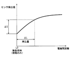
- the initial deformation amount of the elastic member in the initial state where the pushing operation is not performed varies. If the characteristic line representing the relationship between the amount of elastic deformation change (pushing amount) caused by the pushing operation and the sensor output value is a curve (non-linear), the pushing operation is performed due to the above variation. The determination accuracy of whether or not has deteriorated. For example, in the case of the characteristic lines illustrated in FIGS. 5 and 6, the sensor change amount ⁇ S varies even if the push amount ⁇ L is the same.
- the purpose of the present disclosure is to provide an operating device that improves the accuracy of determining whether or not a push-in operation has been performed.
- An operation device includes an operation plate provided with an operation surface to be pushed by an operation body, an assembly member assembled to the operation plate, and the operation plate opposite to the operation surface And a first elastic member that is sandwiched between the operation plate and the assembly member and elastically deformed by a pressing force by the operating body, and the first elasticity generated by the pressing operation
- a sensor that detects the amount of change in elastic deformation of the member, a push determination device that determines whether or not the push operation has been performed based on a detection value of the sensor, and a sandwiched between the operation plate and the assembly member.
- a second elastic member that is elastically deformed together with the first elastic member by the pushing force. The first elastic member and the second elastic member are arranged so that the pushing force is applied in series.
- FIG. 1 is a perspective view showing a vehicle mounting position of the operating device according to the first embodiment of the present disclosure
- FIG. 2 is a front view of the operating device shown in FIG.
- FIG. 3 is a cross-sectional view taken along line III-III in FIG. 2 and shows a state in which a contact operation is performed.
- FIG. 4 is a cross-sectional view showing a state in which the operating device according to the first embodiment is pushed.
- FIG. 5 is a diagram showing a characteristic line representing the relationship between the distance between the electrodes and the sensor detection value, and also showing a change amount ⁇ S of the detection value with respect to the push amount ⁇ L when the assembly tolerance is zero.
- FIG. 6 is a diagram showing a characteristic line representing the relationship between the distance between the electrodes and the sensor detection value, and also showing the change amount ⁇ S of the detection value with respect to the push amount ⁇ L when there is a displacement A due to the assembly tolerance.
- FIG. 7 is a cross-sectional view illustrating a state in which the operation device according to the second embodiment of the present disclosure is in a contact operation
- FIG. 8 is a cross-sectional view showing a state in which the operating device according to the second embodiment is pushed.
- FIG. 9 is a cross-sectional view illustrating an operating device according to a third embodiment of the present disclosure
- FIG. 10 is a cross-sectional view illustrating an operating device according to the fourth embodiment of the present disclosure.
- FIG. 1 is a perspective view of an instrument panel (instrument panel 2) mounted on a vehicle 1 as viewed from the indoor side.
- a display device 4 and an operation device 5 are attached to a central portion of the instrument panel 2 in the left-right direction of the vehicle.
- the panel 3 is assembled in the opening 2 a formed in the instrument panel 2.
- the display surface of the display device 4 and the front portion of the operation device 5 are exposed from the opening 2 a formed in the panel 3.
- the display device 4 displays the contents set by operating the operation device 5 by the vehicle occupant as a user.
- the operation device 5 includes an operation plate 10, a first electrode sheet 20, a first elastic member 30, a second electrode 40, a second elastic member 50, and an assembly member 60 described below. And a microcomputer (microcomputer 70).
- the operation plate 10 is a resin member formed in a bottomed cylindrical shape having a cylindrical portion 101 and a bottom portion 102. On the bottom portion 102, a decorative surface 10a that is visually recognized by the user is formed.
- the decorative surface 10 a has a plurality of operation surfaces 11, 12, 13, 14, 15, and 16. On these operation surfaces 11 to 16, characters, symbols, figures and the like representing the setting contents of the operation target are printed.
- the operation target is an air conditioner 80 that air-conditions the interior of the vehicle. For example, activation of the air conditioner 80, air volume setting, temperature setting, and the like are given as specific examples of the setting contents.
- the cylinder portion 101 has a cylindrical shape extending from the periphery of the bottom portion 102 to the opposite side of the decorative surface 10a.
- the extended end portion of the tubular portion 101 is assembled to the resin assembling member 60. This assembly structure will be described in detail later.
- the display device 4 is caused to display an image having contents for notifying which of the plurality of operation surfaces 11 to 16 is the operation surface selected by the contact operation.
- an alarm sound for notifying that is generated.
- the user can push the operation surfaces 11 to 16 with the fingertip F while the setting can be changed, the corresponding setting contents are changed.
- the operation surface 13 is touched, the automatic control setting of the air conditioner 80 can be changed.
- the automatic control ON / OFF setting is switched.
- a command signal for instructing the operation is output from the microcomputer 70 to the air conditioner 80, and the switching of the air-conditioning air outlet and the air volume are automatically controlled.
- the first electrode sheet 20 is attached to the surface of the operation plate 10 opposite to the decorative surface 10a with an adhesive.
- the first electrode sheet 20 includes a plurality of first electrodes 21, 22, 23, 24, 25, 26 and a ground electrode 21a.
- the first electrodes 21 to 26 and the ground electrode 21a are held by a resin sheet 20a.
- Each of the first electrodes 21 to 26 is disposed at a position facing the corresponding operation surface 11 to 16.
- the ground electrode 21a has a shape extending along the outer edges of the first electrodes 21 to 26. In FIG. 2, the ground electrode 21 a extending along the outer edge of the first electrode 21 is illustrated, and the ground electrodes along the other first electrodes 22 to 26 are not illustrated.
- the sheet-like second electrode 40 is disposed on the opposite side of the operation plate 10 with respect to the first electrode sheet 20 and is spaced apart by a predetermined distance.
- a first elastic member 30 is disposed between the first electrode sheet 20 and the second electrode 40.
- the predetermined distance corresponds to the thickness dimension L1 of the first elastic member 30.
- a second elastic member 50 is disposed on the opposite side of the first elastic member 30 with respect to the second electrode 40.
- the first elastic member 30 and the second elastic member 50 are made of an elastic material such as foamable resin or rubber.
- the first elastic member 30 and the second elastic member 50 are set to have the same thickness dimensions L1 and L2 in a state where they are not elastically deformed.
- the longitudinal elastic modulus of the first elastic member 30 is set smaller than the longitudinal elastic modulus of the second elastic member 50. That is, the first elastic member 30 is softer and easier to deform than the second elastic member 50.
- the first elastic member 30 has a frame part 31 and a girder part 32.
- the frame portion 31 has an annular shape extending along the outer periphery of the decorative surface 10a.
- the girder portion 32 has a linear shape that connects the inside of the frame portion 31, and forms a plurality of openings 30 a inside the frame portion 31.
- the shapes and positions of the frame portion 31 and the girder portion 32 are set so that the operation surfaces 11 to 16 are positioned in the opening 30a when viewed from the decorative surface 10a side (operation side) with respect to the operation plate 10.
- the second elastic member 50 has a shape having a frame part and a girder part, and has a plurality of openings 50a.
- the position of the opening 50a of the second elastic member 50 matches the position of the opening 30a of the first elastic member 30 when viewed from the operation side. That is, it can be said that the first elastic member 30 and the second elastic member 50 are arranged outside the region overlapping the operation surface 11 when viewed from the direction of the push operation.
- the first electrode sheet 20, the first elastic member 30, the second electrode 40, and the second elastic member 50 extend in the extending direction of the cylindrical portion 101 (in FIG. 3). They are stacked in the vertical direction.
- the first electrode sheet 20, the first elastic member 30, the second electrode 40, and the second elastic member 50 are stacked and received in a storage chamber formed inside the operation plate 10 and the assembly member 60. ing.
- the 1st elastic member 30 and the 2nd elastic member 50 are accommodated in the state elastically deformed in the lamination direction. Both surfaces of the first elastic member 30 are bonded to the first electrode sheet 20 and the second electrode 40 with an adhesive. Both surfaces of the second elastic member 50 are bonded to the second electrode 40 and the assembly member 60 with an adhesive.
- Engagement portions 103 having engagement surfaces 103a are formed at a plurality of locations on the extending end of the cylinder portion 101.
- An engagement hole 61 into which the engagement portion 103 is fitted is formed in a portion of the side surface of the assembly member 60 facing the engagement portion 103.
- the engaging surface 103 a of the engaging portion 103 and the engaged surface 61 a of the engaging hole 61 are engaged against the elastic force of the first elastic member 30 and the second elastic member 50. This prevents the engaging portion 103 from coming out of the engaging hole 61.
- the operation plate 10 is stacked on the assembly member 60 with the tapered surface 103 b of the engagement portion 103 pressed against the corner of the assembly member 60. Press in the direction.
- the cylindrical portion 101 is elastically deformed in a direction in which the opening of the operation plate 10 is expanded in a predetermined direction, and the engaging portion 103 is fitted into the engaging hole 61.
- FIG. 3 shows a state where the user touches the operation surface 11 with the fingertip F (operation body), that is, a contact operation.
- the engagement surfaces 103a and 61a remain in the initial state where they are in contact with each other.
- a pressing operation is performed to push the fingertip F that is in contact operation in a direction perpendicular to the decorative surface 10a, that is, in the stacking direction, as shown in FIG. And move relatively to the back side in the pushing direction.
- the operation plate 10 is pushed in while further elastically deforming the first elastic member 30 and the second elastic member 50, the engaging surface 103a is separated from the engaged surface 61a, and the engaging portion 103 is engaged.
- the inside of the hole 61 is moved and it will be in the state of FIG. That is, the separation distance between the engaging surface 103a and the engaged surface 61a corresponds to the pressing amount ⁇ L by the pressing operation.
- the difference between the thickness dimension L1 of the first elastic member 30 at the time of the contact operation and the thickness dimension L1 of the first elastic member 30 at the time of the pressing operation is a deformation amount by which the first elastic member 30 is elastically deformed by the pressing operation.
- This deformation amount is referred to as a first deformation amount ⁇ L1 in the following description.
- the difference between the thickness dimension L2 of the second elastic member 50 at the time of the contact operation and the thickness dimension L2 of the second elastic member 50 at the time of the pressing operation is a deformation amount by which the second elastic member 50 is elastically deformed by the pressing operation.
- This deformation amount is referred to as a second deformation amount ⁇ L2 in the following description.
- the first elastic member 30 and the second elastic member 50 are arranged side by side in the pushing operation direction. Therefore, the pushing force related to the pushing operation is applied to the first elastic member 30 and the second elastic member 50 in series. Therefore, a value obtained by adding the second deformation amount ⁇ L2 to the first deformation amount ⁇ L1 corresponds to the pushing amount ⁇ L.
- the elastic deformation amount of the first elastic member 30 in the initial state shown in FIG. 3 is referred to as a first initial deformation amount ⁇ L1a
- the elastic deformation amount of the second elastic member 50 in the initial state is the second initial deformation amount. It is described as ⁇ L2a.
- These initial deformation amounts vary due to assembly tolerances of the operation plate 10 and the assembly member 60. For example, the variation occurs due to a dimensional error of the extending length L3 of the cylindrical portion 101, a dimensional error of the engagement hole 61, a thickness dimensional error of the first elastic member 30 and the second elastic member 50, and the like.
- the first electrode 21 and the second electrode 40 function as a sensor that detects the first deformation amount ⁇ L1 that is generated by the pressing operation. This function will be described in detail below.
- the capacitance C1 (see FIG. 3) formed between the first electrodes 21 to 26 and the fingertip F changes.
- the first electrode 21 to 26 and the second electrode 40 are separated from each other, that is, the thickness L1 of the first elastic member 30 is reduced.
- the capacitance C2 (see FIG. 3) formed between 21 to 26 and the second electrode 40 changes.
- the microcomputer 70 includes a central processing unit (CPU 70a) and a storage device (memory 70b).
- the CPU 70a functions as a detection device 72, a contact determination device 73, and a push determination device 74 described below by executing arithmetic processing according to a program stored in the memory 70b (see FIG. 2).
- the detection device 72 repeats charging / discharging the first electrodes 21 to 26 forming the capacitances C1 and C2 described above, and counts the number of times of charging / discharging until a predetermined condition is satisfied.
- the value is large. Therefore, the count value is a value representing the capacitance, and the change amount of the count value corresponds to the detection value of the sensor corresponding to the change amount of the capacitance.
- a predetermined voltage for example, 1 V
- the ground electrode 21a is connected to a ground terminal (not shown).
- the second electrode 40 is a floating electrode that is not connected to any terminal.
- the ground electrode 21a exhibits a function of suppressing a signal corresponding to the capacitance of the first electrodes 21 to 26 from being affected by noise.
- the contact determination device 73 determines that a contact operation is being performed when the detected value is equal to or greater than the first threshold value TH1 and the state continues for a predetermined time or more.
- the push determination device 74 determines that a push operation is being performed when the detected value is equal to or greater than the second threshold value TH2.
- the first threshold value TH1 is set to a value smaller than the second threshold value TH2.
- the curve in FIG. 5 is a characteristic line representing the relationship between the distance between the first electrode 21 and the second electrode 40 and the detection value of the sensor, and this characteristic line is non-linear.
- the separation distance is the thickness dimension L1 of the first elastic member 30.
- the symbol L0 in the figure indicates the separation distance during the contact operation.
- FIG. 5 shows a change amount ⁇ S of the detected value with respect to the push amount ⁇ L due to the push operation when the above-described assembly tolerance is zero.
- FIG. 6 shows the change amount ⁇ S of the detected value with respect to the push amount ⁇ L when the first initial deformation amount ⁇ L1a is increased by the amount indicated by the symbol A due to the assembly tolerance. Since the characteristic line is non-linear, as shown in FIGS. 5 and 6, even if the push amount ⁇ L is the same, the change amount ⁇ S is different. Therefore, the determination accuracy by the indentation determination device 74 is improved as the variation in the first initial deformation amount ⁇ L1a due to the assembly tolerance is smaller.
- the microcomputer 70 changes the setting content of the air conditioner 80 associated with the operation surface 11 corresponding to the contact operation.
- Specific examples of the setting include the above-described activation of the air conditioner, air volume setting, temperature setting, and the like.
- the microcomputer 70 outputs a command signal corresponding to the above setting to the air conditioner 80 to control the operation of the air conditioner 80.
- the microcomputer 70 executes a setting change for the setting content selected by the contact operation. For example, the air volume setting or temperature setting of the air conditioner is changed.
- the operating device 5 can function the audio device 81 and the navigation device 82 in addition to the air conditioner 80 as an operation target.
- the microcomputer 70 outputs a command signal corresponding to the setting content by the operation device 5 to the audio device 81 and the navigation device 82 and controls the operation of these devices 81 and 82.
- the second elastic member 50 that is not to be detected is provided separately from the first elastic member 30 that is to be detected by the sensor.
- the second elastic member 50 is sandwiched between the operation plate 10 and the assembly member 60 and is elastically deformed together with the first elastic member 30 by the pushing force.
- the 1st elastic member 30 and the 2nd elastic member 50 are arrange
- the assembly tolerance of the operation plate 10 and the assembly member 60 is absorbed by both the first initial deformation amount and the second initial deformation amount.
- the displacement A is dispersed in the first initial deformation amount and the second initial deformation amount.
- the assembly tolerance added to the first initial deformation amount is reduced by the amount added to the second initial deformation amount, and as a result, the variation in the first initial deformation amount due to the assembly tolerance is reduced.
- the detection target of the first electrode 21 (sensor) is the elastic deformation change amount of the first elastic member 30, and the second elastic member 50 is not the detection target. Therefore, the determination accuracy of whether or not the pushing operation has been performed is improved by the amount by which the variation in the first initial deformation amount is reduced.
- the longitudinal elastic modulus of the first elastic member 30 is set to be smaller than the longitudinal elastic modulus of the second elastic member 50. That is, the first elastic member 30 is softer than the second elastic member 50. Therefore, it is possible to suppress the value of the second threshold value ⁇ TH from being reduced, and the above-described concern can be suppressed.
- the senor includes the first electrodes 21 to 26 and the second electrode 40 that are arranged so that the distance between them is changed by the pushing force, and the first electrode 21 to 26 and the second electrode 40 are arranged.
- the detection value is output based on the change in capacitance generated between the two.
- the first elastic member 30 is disposed between the first electrodes 21 to 26 and the second electrode 40, and the second elastic member 50 is disposed on the opposite side of the first elastic member 30 with respect to the second electrode 40. Is done. According to this, it is possible to realize with a simple configuration that the second elastic member 50 is excluded from the detection target while the change amount of the elastic deformation of the first elastic member 30 is set as the detection target of the sensor.
- a plurality of operation surfaces 11 to 16 are provided on the operation plate 10, and the first electrodes 21 to 26 are provided for each of the plurality of operation surfaces 11 to 16.
- a contact determination device 73 is provided for determining which of the plurality of operation surfaces 11 to 16 is in contact with the first electrode 21 to 26 based on a change in capacitance with respect to each of the first electrodes 21 to 26. According to this, the first electrodes 21 to 26 used for the push determination of the push determination device 74 are also used for the contact determination of the contact determination device 73. Therefore, compared with the case where separate electrodes are used for each of the contact determination device 73 and the push determination device 74, the configuration of the operation device 5 can be simplified.
- the operation device 5 is a capacitance-type device that detects a change in capacitance caused by a push operation and determines whether or not the push operation is performed.
- the present embodiment shown in FIG. 7 is a resistance type device that detects a change in electrical resistance caused by a push operation and determines the presence or absence of the push operation.
- first electrode sheet 20 and the second electrode 40 shown in FIG. 3 are changed to a first conductive sheet 200 and a second conductive sheet 400 shown in FIG.
- These conductive sheets 200 and 400 include a resin sheet having electrical insulation and a conductive ink printed on the resin sheet.
- a surface of the first conductive sheet 200 on which conductive ink is printed is referred to as a first conductive surface 201
- a surface of the second conductive sheet 400 on which conductive ink is printed is referred to as a second conductive surface 401.
- the first conductive surface 201 and the second conductive surface 401 face each other.
- the first elastic member 30 is disposed between the first conductive sheet 200 and the second conductive sheet 400.
- the second elastic member 50 is disposed between the second conductive sheet 400 and the assembly member 60.
- FIG. 7 shows a state in which the operation surface 11 is touched with the fingertip F.
- the engagement surfaces 103a and 61a remain in the initial state where they are in contact with each other.
- the operation plate 10 is relatively moved toward the back side in the pressing direction with respect to the assembly member 60. Moving. Specifically, when the operation plate 10 is pushed in while further elastically deforming the first elastic member 30 and the second elastic member 50, the engaging surface 103a is separated from the engaged surface 61a, and the engaging portion 103 is engaged. The inside of the hole 61 is moved to the state shown in FIG.
- the bottom 102 of the operation plate 10 is elastically deformed by the pushing force. Specifically, the bottom portion 102 is bent and deformed in the pushing direction with the cylindrical portion 101 as a fulcrum. The amount of bending deformation is maximized at the central portion of the bottom 102.
- the central portion of the bottom portion 102 is positioned in the opening 30a of the first elastic member 30, and when the bending deformation is sufficiently large, The conductive surface 201 is in contact with the second conductive surface 401.
- the fingertip F is further pushed and the operation plate 10 is further bent and deformed in a state where the first conductive surface 201 is in contact with the second conductive surface 401, the first conductive surface 201 is further pressed against the second conductive surface 401, and the first conductive surface 201 is pressed.
- the contact area between the conductive surface 201 and the second conductive surface 401 increases. The larger the contact area, the smaller the resistance of electricity flowing from the first conductive surface 201 to the second conductive surface 401.
- the push determination device 74 determines the presence or absence of a push operation based on a signal (detection signal) representing the electrical resistance detected by the detection device.
- the first conductive surface 201 and the second conductive surface 401 function as sensors that detect the first deformation amount ⁇ L ⁇ b> 1 generated by the pressing operation.
- the senor has the first conductive surface 201 and the second conductive surface 401 that are moved by the pressing force and come into contact with each other, and the contact area between the first conductive surface 201 and the second conductive surface 401.
- a detection signal corresponding to is output.
- the first elastic member 30 is disposed between the first conductive surface 201 and the second conductive surface 401, and the second elastic member 50 is on the opposite side of the first elastic member 30 with respect to the second conductive surface 401. Be placed. According to this, it is possible to realize with a simple configuration that the second elastic member 50 is excluded from the detection target while the change amount of the elastic deformation of the first elastic member 30 is set as the detection target of the sensor.
- the first electrode sheet 20 includes a ground electrode 21 a in addition to the first electrode 21.
- the ground electrode 21a is eliminated, and as shown in FIG. 9, the first electrode sheet 20 includes the first electrode 21 but does not include the ground electrode. According to this embodiment, since the ground electrode is eliminated, the structure of the first electrode sheet 20 can be simplified.
- the opening 30 a is formed in the first elastic member 30.
- An opening 50 a is formed in the second elastic member 50.
- the said opening part is abolished and as shown in FIG. 10, the 1st elastic member 30 and the 2nd elastic member 50 are plate shapes which do not have an opening part. According to the present embodiment, when performing the work of attaching the first elastic member 30 and the second elastic member 50 to a predetermined position with an adhesive, the attaching workability can be improved.
- the first embodiment is modified as follows. That is, the first electrodes 21 to 26, the ground electrode 21a, and the sheet 20a are made of a light-transmitting material. Further, in the present embodiment, a light source such as a light emitting diode that transmits and illuminates the operation surfaces 11 to 16 is provided. A light source is provided for each of the operation surfaces 11 to 16, and is disposed on the opposite side of the first elastic member 30 with respect to the second electrode 40.
- the first elastic member 30 and the second elastic member 50 are arranged outside the region overlapping with the operation surfaces 11 to 16 when viewed from the direction of the pushing operation. Yes. Therefore, the operation surfaces 11 to 16 can be transmitted and illuminated without the first elastic member 30 and the second elastic member 50 being visually recognized.
- the display device 4 displays an image that informs which of the plurality of operation surfaces 11 to 16 is the operation surface selected by the contact operation.
- the operation surface selected by the contact operation can be transmitted and illuminated to be notified.
- the thickness dimension L1 of the first elastic member 30 and the thickness dimension L2 of the second elastic member 50 in a state where they are not elastically deformed are set to be the same.
- L1> L2 is set to be the same.
- L1 ⁇ L2 is set to be the same.
- the longitudinal elastic modulus of the first elastic member 30 is set to be smaller than the longitudinal elastic modulus of the second elastic member 50.
- the magnitude relationship of these longitudinal elastic coefficients may be set in reverse, or both longitudinal elastic coefficients may be set to be the same.
- the second elastic member 50 is disposed on the opposite side of the first elastic member 30 with respect to the second electrode 40.
- the second elastic member 50 may be disposed on the opposite side of the first elastic member 30 with respect to the first electrodes 21 to 26.
- the first electrodes 21 to 26 are held inside the sheet 20a.
- the first electrodes 21 to 26 may be printed on the surface of the sheet 20a.
- the sheet-like second electrode 40 is employed.
- seats similarly to the 1st electrode sheet 20 may be sufficient.
- the second electrode 40 may be printed on the surface of the resin sheet.
- the first electrode sheet 20 is embedded and held in the first elastic member 30 shown in FIG. 10 instead of the configuration in which the first electrode sheet 20 is held by the sheet 20 a. It may be configured.
- the first electrodes 21 to 26 used for the determination by the contact determination device 73 are used for the determination by the indentation determination device 74.
- this indication is applicable also to the operating device 5 which is not provided with the function of the contact determination apparatus 73.
- the operation plate 10 is assembled to the assembly member 60 so as to be movable in the pushing operation direction. Specifically, the engaging portion 103 moves in the engaging hole 61.
- the operation plate 10 may be assembled to the assembly member 60 in a state in which it cannot move, and the operation plate 10 may be elastically deformed and bent by the pushing operation, and the amount of bending may be set as the pushing operation amount.
- the user's fingertip F is operated while being in contact with the operation surfaces 11 to 16, and the fingertip F is used as the operating body.
- the user may hold a pen-shaped operation member and operate it by bringing the operation member into contact with the operation surfaces 11 to 16.
- an operation member other than the human body functions as the operation body.
- the gloves function as an operating body.
Landscapes
- Engineering & Computer Science (AREA)
- General Engineering & Computer Science (AREA)
- Theoretical Computer Science (AREA)
- Human Computer Interaction (AREA)
- Physics & Mathematics (AREA)
- General Physics & Mathematics (AREA)
- Power Engineering (AREA)
- Push-Button Switches (AREA)
- Input From Keyboards Or The Like (AREA)
Abstract
操作装置は、操作体(F)により押込操作される操作面(11、12、13、14、15、16)が設けられた操作プレート(10)と、前記操作プレートに組み付けられる組付部材(60)と、前記操作プレートに対して前記操作面の反対側に配置されるとともに、前記操作プレートと前記組付部材との間に挟まれて、前記操作体による押込力で弾性変形する第1弾性部材(30)と、前記押込操作に伴い生じた前記第1弾性部材の弾性変形変化量を検出するセンサ(21、40、72、200、400)と、前記センサの検出値に基づき、前記押込操作が為されたか否かを判定する押込判定装置(74)と、前記操作プレートと前記組付部材との間に挟まれて、前記押込力により前記第1弾性部材とともに弾性変形する第2弾性部材(50)と、を備える。前記第1弾性部材および前記第2弾性部材は、前記押込力が直列に付与されるように配置されている。
Description
本開示は、2015年7月14日に出願された日本出願番号2015-140769号に基づくもので、ここにその記載内容を援用する。
本開示は、操作プレートの操作面を押し込んで操作する操作装置に関する。
特許文献1には、操作者が指先(操作体)で操作プレートの操作面を押込操作すると、その押込力に応じた検出信号を出力する操作装置が知られている。この操作装置は、上記操作プレートに組み付けられる組付部材と、操作プレートと組付部材との間に挟まれて操作体の押込力で弾性変形する弾性部材と、その弾性変形の変化量(弾性変形変化量)を検出するセンサと、を備える。
これによれば、センサ出力値の変化量(センサ変化量)が所定の閾値以上である場合に、押込操作が為されたと判定し、その押込操作に対応する指令信号、例えば車載空調装置へ作動開始を指令する信号等を出力させることができる。
しかしながら、操作プレートおよび組付部材の組付け公差に起因して、押込操作が為されていない初期状態における弾性部材の初期変形量にはバラツキが生じる。そして、押込操作により生じた弾性変形変化量(押込量)とセンサ出力値との関係を表した特性線が曲線(非線形)である場合には、上記バラツキに起因して、押込操作が為されたか否かの判定精度が悪くなる。例えば、図5および図6に例示する特性線の場合において、押込量ΔLが同じであってもセンサ変化量ΔSは異なってくる。
本開示の目的は、押込操作が為されたか否かの判定精度の向上を図った操作装置を提供することにある。
本開示の一態様に係る操作装置は、操作体により押込操作される操作面が設けられた操作プレートと、前記操作プレートに組み付けられる組付部材と、前記操作プレートに対して前記操作面の反対側に配置されるとともに、前記操作プレートと前記組付部材との間に挟まれて、前記操作体による押込力で弾性変形する第1弾性部材と、前記押込操作に伴い生じた前記第1弾性部材の弾性変形変化量を検出するセンサと、前記センサの検出値に基づき、前記押込操作が為されたか否かを判定する押込判定装置と、前記操作プレートと前記組付部材との間に挟まれて、前記押込力により前記第1弾性部材とともに弾性変形する第2弾性部材と、を備える。前記第1弾性部材および前記第2弾性部材は、前記押込力が直列に付与されるように配置されている。
これによれば、押込操作が為されていない初期状態における第1弾性部材の初期変形量(第1初期変形量)および第2弾性部材の初期変形量(第2初期変形量)の両方で、操作プレートおよび組付部材の組付け公差が吸収される。よって、第1初期変形量は第2初期変形量の分だけ少なくなり、ひいては、組付け公差に起因した第1初期変形量のバラツキが小さくなる。そして、センサの検出対象は第1弾性部材であり、第2弾性部材は検出対象外であるため、第1初期変形量のバラツキが小さくなった分だけ、押込操作が為されたか否かの判定精度が向上する。
本開示についての上記目的およびその他の目的、特徴や利点は、添付の図面を参照しながら下記の詳細な記述により、より明確になる。その図面は、
図1は、本開示の第1実施形態に係る操作装置の、車両搭載位置を示す斜視図であり、
図2は、図1に示す操作装置の正面図であり、
図3は、図2のIII-III線に沿う断面図であって、接触操作されている状態を示す図であり、
図4は、第1実施形態に係る操作装置の、押込操作されている状態を示す断面図であり、
図5は、電極間距離とセンサ検出値との関係を表した特性線を示すとともに、組付け公差がゼロである場合における、押込量ΔLに対する検出値の変化量ΔSを示す図であり、
図6は、電極間距離とセンサ検出値との関係を表した特性線を示すとともに、組付け公差による変位Aが存在する場合における、押込量ΔLに対する検出値の変化量ΔSを示す図であり、
図7は、本開示の第2実施形態に係る操作装置の、接触操作されている状態を示す断面図であり、
図8は、第2実施形態に係る操作装置の、押込操作されている状態を示す断面図であり、
図9は、本開示の第3実施形態に係る操作装置を示す断面図であり、及び、
図10は、本開示の第4実施形態に係る操作装置を示す断面図である。
以下、図面を参照しながら本開示に係る操作装置を実施するための複数の形態を説明する。各形態において、先行する形態で説明した事項に対応する部分には同一の参照符号を付して重複する説明を省略する場合がある。各形態において、構成の一部のみを説明している場合は、構成の他の部分については先行して説明した他の形態を参照し適用することができる。
(第1実施形態)
図1は、車両1に搭載されたインストルメントパネル(インパネ2)を室内側から見た斜視図である。インパネ2のうち車両左右方向の中央部分には、表示装置4および操作装置5が取り付けられている。具体的には、インパネ2に形成された開口部2aにパネル3が組み付けられている。そして、パネル3に形成された開口部2aから、表示装置4の表示面および操作装置5の正面部分が露出している。表示装置4には、ユーザである車両乗員が操作装置5を操作して設定した内容が表示される。
図1は、車両1に搭載されたインストルメントパネル(インパネ2)を室内側から見た斜視図である。インパネ2のうち車両左右方向の中央部分には、表示装置4および操作装置5が取り付けられている。具体的には、インパネ2に形成された開口部2aにパネル3が組み付けられている。そして、パネル3に形成された開口部2aから、表示装置4の表示面および操作装置5の正面部分が露出している。表示装置4には、ユーザである車両乗員が操作装置5を操作して設定した内容が表示される。
図2および図3に示すように、操作装置5は、以下に説明する操作プレート10、第1電極シート20、第1弾性部材30、第2電極40、第2弾性部材50、組付部材60、およびマイクロコンピュータ(マイコン70)を備えて構成されている。
操作プレート10は、筒部101および底部102を有する有底筒状に形成された、樹脂製の部材である。底部102には、ユーザに視認される装飾面10aが形成されている。装飾面10aは、複数の操作面11、12、13、14、15、16を有している。これらの操作面11~16には、操作対象の設定内容を表した文字や記号、図形等が印刷されている。図1に示す例では、操作対象は、車室内を空調する空調装置80であり、例えば、空調装置80の起動、風量設定、温度設定等が上記設定内容の具体例として挙げられる。筒部101は、底部102の周縁から装飾面10aの反対側に延びる筒形状である。筒部101の延出端部は、樹脂製の組付部材60に組み付けられる。この組付け構造については、後に詳述する。
ユーザが指先Fで操作面11~16を触れる接触操作をすると、対応する設定内容が設定変更可能な状態になる。例えば、複数の操作面11~16のうち接触操作により選択された操作面がいずれであるかを報知する内容の画像を、表示装置4に表示させる。接触操作が為されて設定変更可能な状態になると、その旨を報知するアラーム音を発生させたりする。設定変更可能な状態で、ユーザが指先Fで操作面11~16をさらに押し込む押込操作をすると、対応する設定内容の変更が実行される。例えば、操作面13が接触操作されると、空調装置80の自動制御の設定が変更可能になり、この状態で操作面13が押込操作されると、自動制御のオンオフ設定が切り替わる。例えば自動制御がオン設定に切り替わると、その作動を指令する指令信号がマイコン70から空調装置80へ出力され、空調風の吹出口の切り替えや風量等が自動制御される。
操作プレート10のうち装飾面10aの反対側の面には、第1電極シート20が接着剤で貼り付けられている。第1電極シート20は、複数の第1電極21、22、23、24、25、26およびグランド電極21aを有する。これらの第1電極21~26およびグランド電極21aは、樹脂製のシート20aに保持されている。第1電極21~26の各々は、対応する操作面11~16に対向する位置に配置されている。グランド電極21aは、第1電極21~26の外縁に沿って延びる形状である。図2では、第1電極21の外縁に沿って延びるグランド電極21aを図示しており、他の第1電極22~26に沿うグランド電極については図示を省略している。
第1電極シート20に対して操作プレート10の反対側には、所定距離だけ離間して配置されたシート状の第2電極40が配置されている。第1電極シート20と第2電極40の間には、第1弾性部材30が配置されている。上記所定距離は、第1弾性部材30の厚み寸法L1に相当する。第2電極40に対して第1弾性部材30の反対側には、第2弾性部材50が配置されている。
第1弾性部材30および第2弾性部材50は、発泡性樹脂やゴム等の弾性を有する材質で形成されている。弾性変形していない状態における厚み寸法L1、L2は、第1弾性部材30および第2弾性部材50は同じに設定されている。但し、第1弾性部材30の縦弾性係数は、第2弾性部材50の縦弾性係数よりも小さく設定されている。つまり、第1弾性部材30の方が第2弾性部材50よりも柔らかく変形しやすい。
第1弾性部材30は枠部31および桁部32を有する。枠部31は、装飾面10aの外周に沿って延びる環状の形状である。桁部32は、枠部31の内側を連結する直線形状であり、枠部31の内側に複数の開口部30aを形成する。操作プレート10に対して装飾面10aの側(操作側)から見て、操作面11~16が開口部30aに位置するよう、枠部31および桁部32の形状と位置が設定されている。第2弾性部材50も、第1弾性部材30と同様にして、枠部および桁部を有する形状であり、複数の開口部50aを有する。第2弾性部材50の開口部50aの位置は、第1弾性部材30の開口部30aの位置と、操作側から見て一致する。つまり、第1弾性部材30および第2弾性部材50は、押込操作の方向から見て操作面11と重複する領域の外に配置されていると言える。
操作プレート10の底部102と組付部材60の間において、第1電極シート20、第1弾性部材30、第2電極40および第2弾性部材50は、筒部101の延出方向(図3の上下方向)に積層して配置されている。換言すれば、操作プレート10および組付部材60の内部に形成された収容室に、第1電極シート20、第1弾性部材30、第2電極40および第2弾性部材50が積層して収容されている。第1弾性部材30および第2弾性部材50は、積層方向に弾性変形した状態で収容されている。第1弾性部材30の両面は、第1電極シート20および第2電極40に接着剤で接着されている。第2弾性部材50の両面は、第2電極40および組付部材60に接着剤で接着されている。
次に、操作プレート10と組付部材60の組付け構造について詳細に説明する。筒部101の延出端の複数箇所には、係合面103aを有する係合部103が形成されている。組付部材60の側面のうち係合部103に対向する部分には、係合部103が嵌り込む係合穴61が形成されている。図3の状態では、第1弾性部材30および第2弾性部材50の弾性力に抗して、係合部103の係合面103aと係合穴61の被係合面61aとが係合することにより、係合部103が係合穴61から抜け出ることを防止している。
なお、操作プレート10を組付部材60に組付ける作業においては、係合部103のテーパ面103bを組付部材60の角部に押し当てた状態で、操作プレート10を組付部材60に積層方向へ押し付ける。これにより、操作プレート10の開口部が所定方向に押し広げられる向きに筒部101が弾性変形して、係合部103が係合穴61に嵌り込む。
図3は、ユーザが指先F(操作体)を操作面11に接触させた状態、つまり接触操作した状態を示す。この状態では、係合面103a、61aが互いに当接した初期状態のままとなっている。接触操作している指先Fを装飾面10aに対して垂直方向、つまり積層方向の奥側へ押し込む押込操作が為されると、図4に示すように、操作プレート10が組付部材60に対して、押込方向奥側へ相対的に移動する。具体的には、第1弾性部材30および第2弾性部材50をさらに弾性変形させながら操作プレート10を押し込むと、係合面103aが被係合面61aから離れて、係合部103が係合穴61内を移動し、図4の状態になる。つまり、係合面103aと被係合面61aとの離間距離が、押込操作による押込量ΔLに相当する。
接触操作時の第1弾性部材30の厚み寸法L1と、押込操作時の第1弾性部材30の厚み寸法L1との差分が、押込操作により第1弾性部材30が弾性変形した変形量である。この変形量を、以下の説明では第1変形量ΔL1と記載する。接触操作時の第2弾性部材50の厚み寸法L2と、押込操作時の第2弾性部材50の厚み寸法L2との差分が、押込操作により第2弾性部材50が弾性変形した変形量である。この変形量を、以下の説明では第2変形量ΔL2と記載する。第1弾性部材30のおよび第2弾性部材50は、押込操作方向に並んで配置されている。そのため、押込操作に係る押込力が、第1弾性部材30のおよび第2弾性部材50に直列に付与されることとなる。よって、第1変形量ΔL1に第2変形量ΔL2を加算した値が押込量ΔLに相当する。
以下の説明では、図3に示す初期状態における第1弾性部材30の弾性変形量を第1初期変形量ΔL1aと記載し、初期状態における第2弾性部材50の弾性変形量を第2初期変形量ΔL2aと記載する。これらの初期変形量には、操作プレート10および組付部材60の組付け公差に起因してバラツキが生じる。例えば、筒部101の延出長さL3の寸法誤差、係合穴61の寸法誤差、第1弾性部材30および第2弾性部材50の厚み寸法誤差等に起因して、上記バラツキが生じる。
第1電極21および第2電極40は、押込操作に伴い生じた第1変形量ΔL1を検出するセンサとして機能する。この機能について、以下、詳細に説明する。
上述した接触操作が為されると、第1電極21~26と指先Fとの間で形成される静電容量C1(図3参照)が変化する。また、上述した押込操作が為されると、第1電極21~26と第2電極40との離間距離、つまり第1弾性部材30の厚み寸法L1が小さくなることに起因して、第1電極21~26と第2電極40との間で形成される静電容量C2(図3参照)が変化する。
マイコン70は、中央演算処理装置(CPU70a)および記憶装置(メモリ70b)を備える。CPU70aは、メモリ70bに記憶されたプログラムにしたがって演算処理を実行することにより、以下に説明する検出装置72、接触判定装置73、押込判定装置74として機能する(図2参照)。
検出装置72は、先述した静電容量C1、C2を形成する第1電極21~26に対して充放電を繰り返すとともに、所定条件を満たすまでの充放電回数をカウントする。第1電極21~26と指先Fとの間で生じる静電容量C1と、第1電極21~26と第2電極40との間で生じる静電容量C2との結合容量が大きいほど、上記カウント値は大きい値になる。したがって、このカウント値が静電容量を表わす値であり、カウント値の変化量が、静電容量の変化量に応じたセンサの検出値に相当する。なお、上記充電時には、第1電極21~26に所定の電圧(例えば1V)を印加する。グランド電極21aは、図示しないグランド端子に接続されている。第2電極40は、いずれの端子にも接続されていないフローティング電極である。グランド電極21aは、第1電極21~26の静電容量に応じた信号がノイズの影響を受けることを抑制する機能を発揮する。
接触判定装置73は、検出値が第1閾値TH1以上であり、かつ、その状態が所定時間以上継続した場合に、接触操作が為されていると判定する。押込判定装置74は、検出値が第2閾値TH2以上である場合に、押込操作が為されていると判定する。第1閾値TH1は第2閾値TH2よりも小さい値に設定されている。
図5中の曲線は、第1電極21と第2電極40との離間距離と、センサの検出値との関係を表した特性線であり、この特性線は非線形である。上記離間距離は、第1弾性部材30の厚み寸法L1である。図中の符号L0は接触操作時の離間距離を示す。図5は、先述した組付け公差がゼロの場合における、押込操作による押込量ΔLに対する検出値の変化量ΔSを示す。
一方、図6は、組付け公差に起因して、第1初期変形量ΔL1aが符号Aに示す分だけ大きくなっている場合における、押込量ΔLに対する検出値の変化量ΔSを示す。特性線が非線形であるため、図5および図6に示すように、押込量ΔLが同じであっても変化量ΔSは異なってくる。そのため、組付け公差に起因した第1初期変形量ΔL1aのバラツキが小さいほど、押込判定装置74による判定精度は向上する。
接触判定装置73により接触操作が為されていると判定されると、マイコン70は、接触操作に該当する操作面11に関連付けられた、空調装置80の設定内容を変更可能な状態にする。上記設定の具体例としては、先述した空調装置の起動、風量設定、温度設定等が挙げられる。マイコン70は、上記設定に応じた指令信号を空調装置80に出力し、空調装置80の作動を制御する。押込判定装置74により押込操作が為されていると判定されると、マイコン70は、接触操作により選択された設定内容について、設定変更を実行する。例えば空調装置の風量設定や温度設定を変更する。
なお、操作装置5は、空調装置80の他にも、オーディオ装置81やナビゲート装置82を操作対象として機能させることもできる。この場合、マイコン70は、操作装置5による設定内容に応じた指令信号をオーディオ装置81やナビゲート装置82に出力し、これらの装置81、82の作動を制御する。
以上により、本実施形態では、センサの検出対象となる第1弾性部材30とは別に、検出対象外となる第2弾性部材50が備えられる。その第2弾性部材50は、操作プレート10と組付部材60の間に挟まれて、押込力により第1弾性部材30とともに弾性変形する。そして、第1弾性部材30および第2弾性部材50は、押込力が直列に付与されるように配置されている。
そのため、第1初期変形量および第2初期変形量の両方で、操作プレート10および組付部材60の組付け公差が吸収される。例えば、操作プレート10の筒部101の延出長さL3が狙った寸法よりも変位Aだけ短くなっている場合であっても、第1初期変形量および第2初期変形量に変位Aが分散して加算される。よって、第1初期変形量に加算される組付け公差は、第2初期変形量に加算された分だけ少なくなり、ひいては、組付け公差に起因した第1初期変形量のバラツキが小さくなる。そして、第1電極21(センサ)の検出対象は第1弾性部材30の弾性変形変化量であり、第2弾性部材50は検出対象外である。そのため、第1初期変形量のバラツキが小さくなった分だけ、押込操作が為されたか否かの判定精度が向上する。
ここで、上記設定を採用しない場合には、第2弾性部材50を設けることに起因して、第1弾性部材30および第2弾性部材50の両方に、押込操作に係る押込量が分散される。そのため、押込量に対する第1弾性部材30の弾性変形変化量が、第2弾性部材50に分散された分だけ小さくなる。そのため、押込判定装置74で用いられる第2閾値ΔTHの値を小さくすることを要し、僅かに押し込んだだけで押込操作判定される操作感になることが懸念される。この点を鑑み、本実施形態では、第1弾性部材30の縦弾性係数を、第2弾性部材50の縦弾性係数よりも小さく設定している。つまり、第1弾性部材30の方が第2弾性部材50よりも柔らかい。そのため、第2閾値ΔTHの値を小さくすることを抑制でき、上記懸念を抑制できる。
さらに本実施形態では、センサは、押込力により互いの離間距離が変化するように配置された第1電極21~26および第2電極40を有するとともに、第1電極21~26と第2電極40の間で生じる静電容量変化に基づき検出値を出力する。そして、第1弾性部材30は、第1電極21~26と第2電極40の間に配置され、第2弾性部材50は、第2電極40に対して第1弾性部材30の反対側に配置される。これによれば、第1弾性部材30の弾性変形変化量をセンサの検出対象としつつ、第2弾性部材50を検出対象外にすることを、簡素な構成で実現できる。
さらに本実施形態では、操作面11~16は操作プレート10に複数設けられ、第1電極21~26は複数の操作面11~16の各々に対して設けられている。そして、第1電極21~26の各々に対する静電容量変化に基づき、複数の操作面11~16のいずれが接触操作されているかを判定する接触判定装置73を備える。これによれば、押込判定装置74の押込判定に用いる第1電極21~26を、接触判定装置73の接触判定にも用いる。そのため、接触判定装置73および押込判定装置74の各々に対して別々の電極を用いる場合に比べて、操作装置5の構成を簡素にできる。
(第2実施形態)
上記第1実施形態に係る操作装置5は、押込操作に起因して生じる静電容量の変化を検出して押込操作の有無を判定する、静電容量式の装置である。これに対し、図7に示す本実施形態では、押込操作に起因して生じる電気抵抗の変化を検出して押込操作の有無を判定する、抵抗式の装置である。
上記第1実施形態に係る操作装置5は、押込操作に起因して生じる静電容量の変化を検出して押込操作の有無を判定する、静電容量式の装置である。これに対し、図7に示す本実施形態では、押込操作に起因して生じる電気抵抗の変化を検出して押込操作の有無を判定する、抵抗式の装置である。
具体的には、図3に示す第1電極シート20および第2電極40を、図7に示す第1導電シート200および第2導電シート400に変更している。これらの導電シート200、400は、電気絶縁性を有する樹脂製シートと、樹脂製シートに印刷された導電性を有するインクと、を備える。第1導電シート200のうち導電性インクが印刷された面を第1導電面201と呼び、第2導電シート400のうち導電性インクが印刷された面を第2導電面401と呼ぶ。第1導電面201と第2導電面401は対向する。第1弾性部材30は、第1導電シート200と第2導電シート400の間に配置されている。第2弾性部材50は、第2導電シート400と組付部材60の間に配置されている。
図7は、指先Fで操作面11を接触操作した状態を示す。この状態では、係合面103a、61aが互いに当接した初期状態のままとなっている。接触操作している指先Fを積層方向の奥側へ押し込む押込操作が為されると、図8に示すように、操作プレート10が組付部材60に対して、押込方向奥側へ相対的に移動する。具体的には、第1弾性部材30および第2弾性部材50をさらに弾性変形させながら操作プレート10を押し込むと、係合面103aが被係合面61aから離れて、係合部103が係合穴61内を移動し、図8の状態になる。さらに、操作プレート10の底部102が押込力により弾性変形する。詳細には、底部102が、筒部101を支点として押し込み方向に曲げ変形する。底部102の中央部分で曲げ変形量が最大となる。
このような曲げ変形が生じると、図8に示すように、第1弾性部材30の開口部30aに底部102の中央部分が位置することとなり、その曲げ変形が十分に大きい場合には、第1導電面201が第2導電面401に接触する。第1導電面201が第2導電面401に接触した状態でさらに指先Fを押し込んで操作プレート10をさらに曲げ変形させると、第1導電面201が第2導電面401にさらに押し付けられ、第1導電面201と第2導電面401との接触面積が増大する。この接触面積が大きいほど、第1導電面201から第2導電面401へ流れる電気の抵抗が小さくなる。つまり、押込量ΔLが大きいほど電気抵抗が小さくなり、この電気抵抗を検出装置が検出する。押込判定装置74は、検出装置により検出された電気抵抗を表わす信号(検出信号)に基づき、押込操作の有無を判定する。本実施形態では、第1導電面201および第2導電面401が、押込操作に伴い生じた第1変形量ΔL1を検出するセンサとして機能する。
以上により、本実施形態では、センサは、押込力により移動して互いに接触する第1導電面201および第2導電面401を有するとともに、第1導電面201と第2導電面401との接触面積に応じた検出信号を出力する。そして、第1弾性部材30は、第1導電面201と第2導電面401の間に配置され、第2弾性部材50は、第2導電面401に対して第1弾性部材30の反対側に配置される。これによれば、第1弾性部材30の弾性変形変化量をセンサの検出対象としつつ、第2弾性部材50を検出対象外にすることを、簡素な構成で実現できる。
(第3実施形態)
図3に示す上記第1実施形態では、第1電極シート20が、第1電極21に加えてグランド電極21aを備える。これに対し本実施形態では、上記グランド電極21aを廃止しており、図9に示すように、第1電極シート20は第1電極21を備えるものの、グランド電極を備えていない。本実施形態によれば、グランド電極を廃止しているので第1電極シート20の構造を簡素にできる。
図3に示す上記第1実施形態では、第1電極シート20が、第1電極21に加えてグランド電極21aを備える。これに対し本実施形態では、上記グランド電極21aを廃止しており、図9に示すように、第1電極シート20は第1電極21を備えるものの、グランド電極を備えていない。本実施形態によれば、グランド電極を廃止しているので第1電極シート20の構造を簡素にできる。
(第4実施形態)
図3に示す上記第1実施形態では、第1弾性部材30に開口部30aを形成している。また、第2弾性部材50に開口部50aを形成している。これに対し本実施形態では、上記開口部を廃止しており、図10に示すように、第1弾性部材30および第2弾性部材50は、開口部を有しない板形状である。本実施形態によれば、第1弾性部材30および第2弾性部材50を接着剤で所定位置に貼り付ける作業を実施するにあたり、その貼り付け作業性を向上できる。
図3に示す上記第1実施形態では、第1弾性部材30に開口部30aを形成している。また、第2弾性部材50に開口部50aを形成している。これに対し本実施形態では、上記開口部を廃止しており、図10に示すように、第1弾性部材30および第2弾性部材50は、開口部を有しない板形状である。本実施形態によれば、第1弾性部材30および第2弾性部材50を接着剤で所定位置に貼り付ける作業を実施するにあたり、その貼り付け作業性を向上できる。
(第5実施形態)
本実施形態は、上記第1実施形態を以下のように変形させたものである。すなわち、第1電極21~26、グランド電極21aおよびシート20aには、透光性を有する材質が採用されている。さらに本実施形態では、操作面11~16を透過照明する発光ダイオード等の光源が備えられている。光源は、操作面11~16の各々に対して備えられており、第2電極40に対して第1弾性部材30の反対側に配置されている。
本実施形態は、上記第1実施形態を以下のように変形させたものである。すなわち、第1電極21~26、グランド電極21aおよびシート20aには、透光性を有する材質が採用されている。さらに本実施形態では、操作面11~16を透過照明する発光ダイオード等の光源が備えられている。光源は、操作面11~16の各々に対して備えられており、第2電極40に対して第1弾性部材30の反対側に配置されている。
上記第1実施形態と同様にして本実施形態においても、第1弾性部材30および第2弾性部材50は、押込操作の方向から見て操作面11~16と重複する領域の外に配置されている。そのため、第1弾性部材30および第2弾性部材50が視認されることなく、操作面11~16を透過照明できる。
また、上記第1実施形態では、複数の操作面11~16のうち接触操作により選択された操作面がいずれであるかを報知する内容の画像を、表示装置4に表示させている。これに対し、本実施形態では光源を備えるので、接触操作により選択された操作面を透過照明して報知することができる。
(他の実施形態)
以上、発明の好ましい実施形態について説明したが、発明は上述した実施形態に何ら制限されることなく、以下に例示するように種々変形して実施することが可能である。各実施形態で具体的に組合せが可能であることを明示している部分同士の組合せばかりではなく、特に組合せに支障が生じなければ、明示してなくとも実施形態同士を部分的に組み合せることも可能である。
以上、発明の好ましい実施形態について説明したが、発明は上述した実施形態に何ら制限されることなく、以下に例示するように種々変形して実施することが可能である。各実施形態で具体的に組合せが可能であることを明示している部分同士の組合せばかりではなく、特に組合せに支障が生じなければ、明示してなくとも実施形態同士を部分的に組み合せることも可能である。
上記各実施形態では、弾性変形していない状態における第1弾性部材30の厚み寸法L1および第2弾性部材50の厚み寸法L2は同じに設定されている。これに対し、L1>L2としてもよいし、L1<L2としてもよい。また、上記各実施形態では、第1弾性部材30の縦弾性係数を、第2弾性部材50の縦弾性係数よりも小さく設定している。これに対し、これら縦弾性係数の大小関係を逆に設定してもよいし、両方の縦弾性係数を同じに設定してもよい。
上記各実施形態では、第2弾性部材50は、第2電極40に対して第1弾性部材30の反対側に配置されている。これに対し、第2弾性部材50は、第1電極21~26に対して第1弾性部材30の反対側に配置されていてもよい。
図3に示す実施形態では、第1電極21~26がシート20aの内部に保持された構造である。この構造に替えて、第1電極21~26がシート20aの表面に印刷された構造であってもよい。また、図3に示す実施形態では、シート状の第2電極40を採用している。これに対し、第1電極シート20と同様にして、樹脂製シートの内部に第2電極40を保持させた構造であってもよい。また、樹脂製シートの表面に第2電極40を印刷させた構造であってもよい。
図10に示す上記第4実施形態の変形例として、第1電極シート20をシート20aに保持させる構成に替えて、第1電極シート20を図10に示す第1弾性部材30に埋め込んで保持させる構成にしてもよい。
上記第1実施形態では、接触判定装置73の判定に用いる第1電極21~26を、押込判定装置74の判定に用いている。これに対し、接触判定装置73の機能を備えていない操作装置5にも本開示は適用できる。
上記各実施形態では、押込操作方向に移動可能な状態で操作プレート10が組付部材60に組み付けられている。具体的には、係合部103が係合穴61内を移動する。これに対し、移動不可の状態で操作プレート10を組付部材60に組み付けて、押込操作により操作プレート10が弾性変形して撓み、その撓み量を押込操作量としてもよい。
上記各実施形態では、ユーザの指先Fを操作面11~16に接触させて操作することを想定しており、指先Fを操作体としている。これに対し、例えばペン形状の操作部材をユーザが持ち、その操作部材を操作面11~16に接触させて操作してもよく、この場合には、人体以外の操作部材が操作体として機能する。また、ユーザが手袋をはめた状態で操作面11~16を接触操作した場合には、手袋が操作体として機能する。
本開示は、実施例に準拠して記述されたが、本開示は当該実施例や構造に限定されるものではないと理解される。本開示は、様々な変形例や均等範囲内の変形をも包含する。加えて、様々な組み合わせや形態、さらには、それらに一要素のみ、それ以上、あるいはそれ以下、を含む他の組み合わせや形態をも、本開示の範疇や思想範囲に入るものである。
Claims (5)
- 操作体(F)により押込操作される操作面(11、12、13、14、15、16)が設けられた操作プレート(10)と、
前記操作プレートに組み付けられる組付部材(60)と、
前記操作プレートに対して前記操作面の反対側に配置されるとともに、前記操作プレートと前記組付部材との間に挟まれて、前記操作体による押込力で弾性変形する第1弾性部材(30)と、
前記押込操作に伴い生じた前記第1弾性部材の弾性変形変化量を検出するセンサ(21、40、72、200、400)と、
前記センサの検出値に基づき、前記押込操作が為されたか否かを判定する押込判定装置(74)と、
前記操作プレートと前記組付部材との間に挟まれて、前記押込力により前記第1弾性部材とともに弾性変形する第2弾性部材(50)と、
を備え、
前記第1弾性部材および前記第2弾性部材は、前記押込力が直列に付与されるように配置されている操作装置。 - 前記第1弾性部材の縦弾性係数は、前記第2弾性部材の縦弾性係数よりも小さい請求項1に記載の操作装置。
- 前記センサは、前記押込力により互いの離間距離が変化するように配置された第1電極(21、22、23、24、25、26)および第2電極(40)を有するとともに、前記第1電極と前記第2電極の間で生じる静電容量変化に基づき前記検出値を出力し、
前記第1弾性部材は、前記第1電極と前記第2電極との間に配置され、
前記第2弾性部材は、前記第1電極または前記第2電極に対して前記第1弾性部材の反対側に配置される請求項1または2に記載の操作装置。 - 前記操作面は、前記操作プレートに複数設けられ、
前記第1電極は、複数の前記操作面の各々に対して設けられ、
前記第1電極の各々に対する前記静電容量変化に基づき、複数の前記操作面のいずれが前記操作体により接触操作されているかを判定する接触判定手段(73)を備える請求項3に記載の操作装置。 - 前記センサは、前記押込力により移動して互いに接触する第1導電面(201)および第2導電面(401)を有するとともに、前記第1導電面と前記第2導電面との接触面積に応じた検出信号を出力し、
前記第1弾性部材は、前記第1導電面と前記第2導電面との間に配置され、
前記第2弾性部材は、前記第1導電面または前記第2導電面に対して前記第1弾性部材の反対側に配置される請求項1または2に記載の操作装置。
Priority Applications (1)
| Application Number | Priority Date | Filing Date | Title |
|---|---|---|---|
| US15/740,402 US10254872B2 (en) | 2015-07-14 | 2016-07-05 | Operation apparatus |
Applications Claiming Priority (2)
| Application Number | Priority Date | Filing Date | Title |
|---|---|---|---|
| JP2015-140769 | 2015-07-14 | ||
| JP2015140769A JP6304154B2 (ja) | 2015-07-14 | 2015-07-14 | 操作装置 |
Publications (1)
| Publication Number | Publication Date |
|---|---|
| WO2017010338A1 true WO2017010338A1 (ja) | 2017-01-19 |
Family
ID=57757217
Family Applications (1)
| Application Number | Title | Priority Date | Filing Date |
|---|---|---|---|
| PCT/JP2016/069843 Ceased WO2017010338A1 (ja) | 2015-07-14 | 2016-07-05 | 操作装置 |
Country Status (3)
| Country | Link |
|---|---|
| US (1) | US10254872B2 (ja) |
| JP (1) | JP6304154B2 (ja) |
| WO (1) | WO2017010338A1 (ja) |
Families Citing this family (3)
| Publication number | Priority date | Publication date | Assignee | Title |
|---|---|---|---|---|
| JP6996355B2 (ja) * | 2018-03-06 | 2022-01-17 | 株式会社デンソー | 静電容量式操作装置 |
| DE102023203667A1 (de) * | 2022-04-20 | 2023-10-26 | Witte Automotive Gmbh | Sensormodul |
| WO2024247420A1 (ja) * | 2023-06-01 | 2024-12-05 | アルプスアルパイン株式会社 | 入力装置 |
Citations (3)
| Publication number | Priority date | Publication date | Assignee | Title |
|---|---|---|---|---|
| JPS5767341U (ja) * | 1980-10-09 | 1982-04-22 | ||
| JP2004527847A (ja) * | 2001-04-13 | 2004-09-09 | スリーエム イノベイティブ プロパティズ カンパニー | タッチ位置判定装置における接線力の制御 |
| JP2014142914A (ja) * | 2012-12-24 | 2014-08-07 | Denso Corp | 操作デバイス |
Family Cites Families (7)
| Publication number | Priority date | Publication date | Assignee | Title |
|---|---|---|---|---|
| JPS576341U (ja) | 1980-06-11 | 1982-01-13 | ||
| JP4055378B2 (ja) * | 2001-07-06 | 2008-03-05 | 松下電器産業株式会社 | タッチパネルスイッチ |
| KR100943989B1 (ko) * | 2008-04-02 | 2010-02-26 | (주)엠아이디티 | 정전용량식 터치스크린 |
| JP5347913B2 (ja) * | 2009-11-06 | 2013-11-20 | ソニー株式会社 | センサ装置、電子機器、及びセンサ装置の製造方法 |
| KR20160027679A (ko) * | 2014-09-02 | 2016-03-10 | 삼성전자주식회사 | 디스플레이 장치 |
| KR101668921B1 (ko) * | 2014-12-24 | 2016-10-24 | 엘지전자 주식회사 | 터치 센서 어셈블리 및 터치 센서 어셈블리가 구비된 냉장고 도어 |
| KR102330585B1 (ko) * | 2015-03-23 | 2021-11-24 | 엘지디스플레이 주식회사 | 터치 스크린 장치와 그의 구동 방법, 및 이를 포함하는 휴대용 전자 기기 |
-
2015
- 2015-07-14 JP JP2015140769A patent/JP6304154B2/ja not_active Expired - Fee Related
-
2016
- 2016-07-05 US US15/740,402 patent/US10254872B2/en not_active Expired - Fee Related
- 2016-07-05 WO PCT/JP2016/069843 patent/WO2017010338A1/ja not_active Ceased
Patent Citations (3)
| Publication number | Priority date | Publication date | Assignee | Title |
|---|---|---|---|---|
| JPS5767341U (ja) * | 1980-10-09 | 1982-04-22 | ||
| JP2004527847A (ja) * | 2001-04-13 | 2004-09-09 | スリーエム イノベイティブ プロパティズ カンパニー | タッチ位置判定装置における接線力の制御 |
| JP2014142914A (ja) * | 2012-12-24 | 2014-08-07 | Denso Corp | 操作デバイス |
Also Published As
| Publication number | Publication date |
|---|---|
| JP2017021717A (ja) | 2017-01-26 |
| JP6304154B2 (ja) | 2018-04-04 |
| US10254872B2 (en) | 2019-04-09 |
| US20180188875A1 (en) | 2018-07-05 |
Similar Documents
| Publication | Publication Date | Title |
|---|---|---|
| JP6292186B2 (ja) | 操作装置 | |
| CN108944661B (zh) | 用于机动车辆的控制面板 | |
| JP2004006315A (ja) | 容量型制御部材 | |
| US9385711B2 (en) | Switch device | |
| JP2016120890A (ja) | 車両用スイッチ装置 | |
| CN112840296B (zh) | 用于机动车的操作装置 | |
| US10963053B2 (en) | Display-based switch assembly and methods of use | |
| JP2013054725A (ja) | 入力装置 | |
| WO2017010338A1 (ja) | 操作装置 | |
| WO2014207997A1 (ja) | 入力装置 | |
| KR20160097273A (ko) | 전기장치용 작동장치, 특히 차량부품용 작동장치 | |
| WO2015052887A1 (ja) | 静電容量式スイッチ | |
| US11863176B2 (en) | Operation panel | |
| JP6837555B2 (ja) | 操作検出装置 | |
| US12509015B2 (en) | Steering wheel and method for turning on preset function in vehicle by using steering wheel | |
| CN204808250U (zh) | 包括触摸敏感表面的控制模块 | |
| JP6075607B2 (ja) | ステアリングスイッチ、ステアリングホイール | |
| CN110998500A (zh) | 操作检测装置 | |
| CN109813346B (zh) | 多级电容式传感器 | |
| JP2015130122A (ja) | 静電容量式操作装置 | |
| KR102780654B1 (ko) | 필링 제어기능을 갖는 햅틱 스위치 | |
| US20190278317A1 (en) | Input device | |
| US20250269793A1 (en) | Shift device | |
| JP2023160207A (ja) | シフト装置 | |
| CN114879864A (zh) | 触控操作装置 |
Legal Events
| Date | Code | Title | Description |
|---|---|---|---|
| 121 | Ep: the epo has been informed by wipo that ep was designated in this application |
Ref document number: 16824318 Country of ref document: EP Kind code of ref document: A1 |
|
| NENP | Non-entry into the national phase |
Ref country code: DE |
|
| 122 | Ep: pct application non-entry in european phase |
Ref document number: 16824318 Country of ref document: EP Kind code of ref document: A1 |