WO2017010358A1 - Dispositif d'envoi, procédé d'envoi, dispositif et procédé de réception - Google Patents
Dispositif d'envoi, procédé d'envoi, dispositif et procédé de réception Download PDFInfo
- Publication number
- WO2017010358A1 WO2017010358A1 PCT/JP2016/069954 JP2016069954W WO2017010358A1 WO 2017010358 A1 WO2017010358 A1 WO 2017010358A1 JP 2016069954 W JP2016069954 W JP 2016069954W WO 2017010358 A1 WO2017010358 A1 WO 2017010358A1
- Authority
- WO
- WIPO (PCT)
- Prior art keywords
- metadata
- digital audio
- audio signal
- transmission
- compressed digital
- Prior art date
- Legal status (The legal status is an assumption and is not a legal conclusion. Google has not performed a legal analysis and makes no representation as to the accuracy of the status listed.)
- Ceased
Links
Images









Classifications
-
- H—ELECTRICITY
- H04—ELECTRIC COMMUNICATION TECHNIQUE
- H04N—PICTORIAL COMMUNICATION, e.g. TELEVISION
- H04N21/00—Selective content distribution, e.g. interactive television or video on demand [VOD]
- H04N21/40—Client devices specifically adapted for the reception of or interaction with content, e.g. set-top-box [STB]; Operations thereof
- H04N21/43—Processing of content or additional data, e.g. demultiplexing additional data from a digital video stream; Elementary client operations, e.g. monitoring of home network or synchronising decoder's clock; Client middleware
- H04N21/4302—Content synchronisation processes, e.g. decoder synchronisation
- H04N21/4307—Synchronising the rendering of multiple content streams or additional data on devices, e.g. synchronisation of audio on a mobile phone with the video output on the TV screen
- H04N21/43072—Synchronising the rendering of multiple content streams or additional data on devices, e.g. synchronisation of audio on a mobile phone with the video output on the TV screen of multiple content streams on the same device
-
- G—PHYSICS
- G10—MUSICAL INSTRUMENTS; ACOUSTICS
- G10L—SPEECH ANALYSIS TECHNIQUES OR SPEECH SYNTHESIS; SPEECH RECOGNITION; SPEECH OR VOICE PROCESSING TECHNIQUES; SPEECH OR AUDIO CODING OR DECODING
- G10L19/00—Speech or audio signals analysis-synthesis techniques for redundancy reduction, e.g. in vocoders; Coding or decoding of speech or audio signals, using source filter models or psychoacoustic analysis
- G10L19/008—Multichannel audio signal coding or decoding using interchannel correlation to reduce redundancy, e.g. joint-stereo, intensity-coding or matrixing
-
- G—PHYSICS
- G10—MUSICAL INSTRUMENTS; ACOUSTICS
- G10L—SPEECH ANALYSIS TECHNIQUES OR SPEECH SYNTHESIS; SPEECH RECOGNITION; SPEECH OR VOICE PROCESSING TECHNIQUES; SPEECH OR AUDIO CODING OR DECODING
- G10L19/00—Speech or audio signals analysis-synthesis techniques for redundancy reduction, e.g. in vocoders; Coding or decoding of speech or audio signals, using source filter models or psychoacoustic analysis
- G10L19/04—Speech or audio signals analysis-synthesis techniques for redundancy reduction, e.g. in vocoders; Coding or decoding of speech or audio signals, using source filter models or psychoacoustic analysis using predictive techniques
- G10L19/08—Determination or coding of the excitation function; Determination or coding of the long-term prediction parameters
- G10L19/09—Long term prediction, i.e. removing periodical redundancies, e.g. by using adaptive codebook or pitch predictor
-
- G—PHYSICS
- G10—MUSICAL INSTRUMENTS; ACOUSTICS
- G10L—SPEECH ANALYSIS TECHNIQUES OR SPEECH SYNTHESIS; SPEECH RECOGNITION; SPEECH OR VOICE PROCESSING TECHNIQUES; SPEECH OR AUDIO CODING OR DECODING
- G10L19/00—Speech or audio signals analysis-synthesis techniques for redundancy reduction, e.g. in vocoders; Coding or decoding of speech or audio signals, using source filter models or psychoacoustic analysis
- G10L19/04—Speech or audio signals analysis-synthesis techniques for redundancy reduction, e.g. in vocoders; Coding or decoding of speech or audio signals, using source filter models or psychoacoustic analysis using predictive techniques
- G10L19/16—Vocoder architecture
- G10L19/167—Audio streaming, i.e. formatting and decoding of an encoded audio signal representation into a data stream for transmission or storage purposes
-
- H—ELECTRICITY
- H03—ELECTRONIC CIRCUITRY
- H03M—CODING; DECODING; CODE CONVERSION IN GENERAL
- H03M7/00—Conversion of a code where information is represented by a given sequence or number of digits to a code where the same, similar or subset of information is represented by a different sequence or number of digits
- H03M7/30—Compression; Expansion; Suppression of unnecessary data, e.g. redundancy reduction
- H03M7/3002—Conversion to or from differential modulation
- H03M7/3044—Conversion to or from differential modulation with several bits only, i.e. the difference between successive samples being coded by more than one bit, e.g. differential pulse code modulation [DPCM]
- H03M7/3046—Conversion to or from differential modulation with several bits only, i.e. the difference between successive samples being coded by more than one bit, e.g. differential pulse code modulation [DPCM] adaptive, e.g. adaptive differential pulse code modulation [ADPCM]
-
- H—ELECTRICITY
- H04—ELECTRIC COMMUNICATION TECHNIQUE
- H04N—PICTORIAL COMMUNICATION, e.g. TELEVISION
- H04N21/00—Selective content distribution, e.g. interactive television or video on demand [VOD]
- H04N21/40—Client devices specifically adapted for the reception of or interaction with content, e.g. set-top-box [STB]; Operations thereof
- H04N21/43—Processing of content or additional data, e.g. demultiplexing additional data from a digital video stream; Elementary client operations, e.g. monitoring of home network or synchronising decoder's clock; Client middleware
- H04N21/436—Interfacing a local distribution network, e.g. communicating with another STB or one or more peripheral devices inside the home
- H04N21/4363—Adapting the video stream to a specific local network, e.g. a Bluetooth® network
- H04N21/43632—Adapting the video stream to a specific local network, e.g. a Bluetooth® network involving a wired protocol, e.g. IEEE 1394
- H04N21/43635—HDMI
-
- H—ELECTRICITY
- H04—ELECTRIC COMMUNICATION TECHNIQUE
- H04N—PICTORIAL COMMUNICATION, e.g. TELEVISION
- H04N21/00—Selective content distribution, e.g. interactive television or video on demand [VOD]
- H04N21/40—Client devices specifically adapted for the reception of or interaction with content, e.g. set-top-box [STB]; Operations thereof
- H04N21/43—Processing of content or additional data, e.g. demultiplexing additional data from a digital video stream; Elementary client operations, e.g. monitoring of home network or synchronising decoder's clock; Client middleware
- H04N21/439—Processing of audio elementary streams
-
- H—ELECTRICITY
- H03—ELECTRONIC CIRCUITRY
- H03M—CODING; DECODING; CODE CONVERSION IN GENERAL
- H03M5/00—Conversion of the form of the representation of individual digits
- H03M5/02—Conversion to or from representation by pulses
- H03M5/04—Conversion to or from representation by pulses the pulses having two levels
- H03M5/06—Code representation, e.g. transition, for a given bit cell depending only on the information in that bit cell
- H03M5/12—Biphase level code, e.g. split phase code, Manchester code; Biphase space or mark code, e.g. double frequency code
-
- H—ELECTRICITY
- H03—ELECTRONIC CIRCUITRY
- H03M—CODING; DECODING; CODE CONVERSION IN GENERAL
- H03M7/00—Conversion of a code where information is represented by a given sequence or number of digits to a code where the same, similar or subset of information is represented by a different sequence or number of digits
- H03M7/30—Compression; Expansion; Suppression of unnecessary data, e.g. redundancy reduction
-
- H—ELECTRICITY
- H04—ELECTRIC COMMUNICATION TECHNIQUE
- H04N—PICTORIAL COMMUNICATION, e.g. TELEVISION
- H04N21/00—Selective content distribution, e.g. interactive television or video on demand [VOD]
- H04N21/40—Client devices specifically adapted for the reception of or interaction with content, e.g. set-top-box [STB]; Operations thereof
- H04N21/43—Processing of content or additional data, e.g. demultiplexing additional data from a digital video stream; Elementary client operations, e.g. monitoring of home network or synchronising decoder's clock; Client middleware
- H04N21/439—Processing of audio elementary streams
- H04N21/4392—Processing of audio elementary streams involving audio buffer management
-
- H—ELECTRICITY
- H04—ELECTRIC COMMUNICATION TECHNIQUE
- H04N—PICTORIAL COMMUNICATION, e.g. TELEVISION
- H04N21/00—Selective content distribution, e.g. interactive television or video on demand [VOD]
- H04N21/80—Generation or processing of content or additional data by content creator independently of the distribution process; Content per se
- H04N21/83—Generation or processing of protective or descriptive data associated with content; Content structuring
- H04N21/84—Generation or processing of descriptive data, e.g. content descriptors
Definitions
- the present invention relates to a transmission device, a transmission method, a reception device, and a reception method, and more particularly to a transmission device and a reception device that transmit and receive a compressed digital audio signal.
- Patent Literature 1 describes the IEC 60958 standard.
- IEC 61937 is a standard for transmitting a compressed digital audio signal packetized on IEC 60958-3
- IEC 61937-6 defines a transmission method of MPEG-2 AAC.
- MPEG-2 AAC transmission used in television broadcasting, since both 2 channels and 5.1 channels are compressed, they are output at the same transmission rate as LPCM 48 kHz 2 channels defined in IEC 60958-3.
- MPEG-4 AAC In next-generation television broadcasting, MPEG-4 AAC is used, and the maximum number of audio channels is 22.2 and the data rate is increasing. When this signal is output to the outside, the IEC 19 19937-11 standard is applied. This standard is a standard for transmitting MPEG-4 AAC compressed digital audio signals in the LATM / LOAS format.
- the transmission frequency is the same as the sampling frequency, and if the sampling frequency is 48 kHz, transmission must be performed at 48 kHz.
- the sampling frequency is 48 kHz
- transmission must be performed at 48 kHz.
- transmission at 96 kHz can be considered.
- a device that has received a signal transmitted at 96 kHz performs a wrong process of converting a signal that should originally be converted to analog at 48 kHz into an analog signal at 96 kHz.
- 96 kHz playback is displayed to the user, giving a misunderstanding that an audio signal of 24 kHz or higher is played back.
- the purpose of this technology is to be able to satisfactorily transmit a compressed digital audio signal having a high data rate.
- the concept of this technology is First metadata indicating the transmission frequency of the compressed digital audio signal, a first sampling frequency indicating the sampling frequency used when converting the uncompressed digital audio signal of each channel into an analog signal, to the compressed digital audio signal of a predetermined number of channels
- a metadata adding unit that adds metadata of 2 and third metadata indicating a ratio of the transmission frequency to the sampling frequency;
- the transmission apparatus includes a transmission unit that transmits the compressed digital audio signal to which the metadata is added to an external device via a predetermined transmission path.
- the metadata adding unit adds the first, second, and third metadata to the compressed digital audio signal having a predetermined number of channels.
- the encoding method of the compressed digital audio signal may be MPEG-4 AAC.
- the predetermined number of channels may be 22.2 channels.
- an acquisition unit that acquires a compressed digital audio signal from a broadcast signal or reproduces and acquires a compressed digital audio signal from a recording medium may be provided.
- the first metadata is metadata indicating the transmission frequency of the compressed digital audio signal.
- the second metadata is metadata indicating a sampling frequency used when the uncompressed digital audio signal of each channel is converted into an analog signal.
- the third metadata is metadata indicating the ratio of the transmission frequency to the sampling frequency.
- the transmission unit transmits a compressed digital audio signal to which each metadata is added to an external device via a predetermined transmission path.
- the predetermined transmission line may be a coaxial cable, an optical cable, an Ethernet (IEC 61883-6) cable, an HDMI cable, an MHL cable, or a display port cable.
- the transmitting unit sequentially transmits a compressed digital audio signal for each unit data
- the metadata adding unit uses each bit of the channel status of each block including a predetermined number of continuous unit data. Data may be added.
- a receiving unit that receives a predetermined number of channels of compressed digital audio signals from an external device via a predetermined transmission path;
- the compressed digital audio signal includes first metadata indicating the transmission frequency of the compressed digital audio signal, and second sampling frequency used when converting the uncompressed digital audio signal of each channel into an analog signal.
- Third metadata indicating the ratio of the metadata and the transmission frequency to the sampling frequency is added,
- a receiving apparatus includes a processing unit that performs processing related to the compressed digital audio signal based on at least one of the metadata.
- the receiving unit receives a predetermined number of compressed digital audio signals from an external device via a predetermined transmission path.
- the predetermined transmission path may be a coaxial cable, an optical cable, an Ethernet (IEC 61883-6) cable, an HDMI cable, an MHL cable, or a display port cable.
- the first, second and third metadata are added to the compressed digital audio signal.
- the receiving unit sequentially receives a compressed digital audio signal for each unit data, and the compressed digital audio signal uses each predetermined bit area of the channel status of each block configured by a predetermined number of continuous unit data. Metadata may be added.
- the first metadata is metadata indicating the transmission frequency of the compressed digital audio signal.
- the second metadata is metadata indicating a sampling frequency used when the uncompressed digital audio signal of each channel is converted into an analog signal.
- the third metadata is metadata indicating the ratio of the transmission frequency to the sampling frequency.
- the processing unit performs processing related to the compressed digital audio signal based on at least one of the meta data. For example, the processing unit locks the PLL to a frequency corresponding to the transmission frequency indicated by the first metadata, performs a decoding process on the compressed digital audio signal using a clock signal having a frequency locked by the PLL, An uncompressed digital audio signal for each channel of a predetermined number of channels may be obtained.
- the processing unit converts the uncompressed digital audio signal of each channel obtained by performing the decoding process on the compressed digital audio signal into an analog signal at the sampling frequency indicated by the second metadata and outputs the analog signal You may be like.
- the processing unit may display the sampling frequency indicated by the second metadata on the display unit as the sampling frequency of the output analog audio signal of each channel.
- the processing unit displays the transmission frequency of the compressed digital audio signal on the display unit using the transmission frequency indicated by the first metadata or the ratio indicated by the third metadata. May be.
- the processing unit compares the ratio of the transmission frequency indicated by the first metadata to the sampling frequency indicated by the second metadata with the ratio indicated by the third metadata, thereby comparing the first metadata.
- An error in the data or the second metadata may be detected.
- processing related to the compressed digital audio signal is performed based on the metadata added to the compressed digital audio signal. Therefore, processing related to the compressed digital audio signal, for example, decoding processing, processing for converting to an analog signal, processing for clearly indicating the playback audio frequency band to the user, and the like are appropriately performed.
- a compressed digital audio signal having a high data rate can be transmitted satisfactorily.
- the effects described in the present specification are merely examples and are not limited, and may have additional effects.
- Embodiment> [Example of AV system configuration]
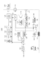
- FIG. 1 shows a configuration example of an AV system 10 as an embodiment.
- the AV system 10 includes a television receiver 100 as a sink device, an audio amplifier 200 as a repeater device, and a BD (Blu-Ray Disc) player 300 as a source device.
- a television broadcast receiving antenna 400 is connected to the television receiver 100 and the BD player 300.
- the audio amplifier 200 is connected to a 2-channel or multi-channel speaker system 500.
- the television receiver 100 and the audio amplifier 200 are connected via an HDMI cable 610.
- the television receiver 100 is provided with an HDMI terminal 101 to which an HDMI receiving unit (HDMI RX) 102 and a high-speed bus interface 103 constituting a communication unit are connected.
- HDMI is a registered trademark.
- the audio amplifier 200 is provided with an HDMI terminal 201a to which an HDMI transmission unit (HDMI TX) 202a and a high-speed bus interface 203a constituting a communication unit are connected.
- HDMI transmission unit HDMI TX
- HDMI TX HDMI transmission unit
- High-speed bus interface 203a constituting a communication unit.
- One end of the above-described HDMI cable 610 is connected to the HDMI terminal 101 of the television receiver 100, and the other end of the HDMI cable 610 is connected to the HDMI terminal 201 a of the audio amplifier 200.
- the audio amplifier 200 and the BD player 300 are connected via an HDMI cable 620.
- the audio amplifier 200 is provided with an HDMI terminal 201b to which an HDMI receiving unit (HDMI RX) 202b and a high-speed bus interface 203b constituting a communication unit are connected.
- HDMI receiving unit HDMI RX
- HDMI high-speed bus interface 203b constituting a communication unit
- the BD player 300 is provided with an HDMI terminal 301 to which an HDMI transmission unit (HDNI TX) 302 and a high-speed bus interface 303 constituting a communication unit are connected.
- HDMI transmission unit HDMI TX
- HDMI terminal 301 to which an HDMI transmission unit (HDNI TX) 302 and a high-speed bus interface 303 constituting a communication unit are connected.
- HDMI cable 620 is connected to the HDMI terminal 201 b of the audio amplifier 200, and the other end of the HDMI cable 620 is connected to the HDMI terminal 301 of the BD player 300.
- FIG. 2 shows a configuration example of the television receiver 100.
- the television receiver 100 includes an HDMI terminal 101, an HDMI receiving unit 102, a high-speed bus interface 103, and a SPDIF (Sony Philips Digital Interface) transmission circuit 104.
- the television receiver 100 also includes an antenna terminal 105, a digital broadcast tuner 106, an MPEG decoder 107, a video signal processing circuit 108, a graphic generation circuit 109, a panel drive circuit 110, and a display panel 111. ing.
- the television receiver 100 includes an audio signal processing circuit 112, an audio amplification circuit 113, a speaker 114, an Ethernet interface (Ethernet I / F) 115, and a network terminal 116.
- the television receiver 100 includes an internal bus 120, a CPU 121, a flash ROM 122, an SDRAM (Synchronous RAM) 123, a display control unit 124, a remote control reception unit 125, a remote control transmitter 126, and a power supply unit 127.
- a CPU 121 a central processing circuit 116
- SDRAM Synchronous RAM
- the CPU 121 controls the operation of each unit of the television receiver 100.
- the flash ROM 122 stores control software and data.
- the SDRAM 123 constitutes a work area for the CPU 121.
- the CPU 121 develops the software and data read from the flash ROM 122 on the SDRAM 123 to activate the software, and controls each unit of the television receiver 100.
- the remote control receiving unit 125 receives a remote control signal (remote control code) transmitted from the remote control transmitter 126 and supplies it to the CPU 121.
- the CPU 121 controls each part of the television receiver 100 based on the remote control code.
- a remote control unit is shown as the user instruction input unit.
- the user instruction input unit has other configurations, for example, a touch panel unit that inputs an instruction by proximity / touch, a mouse, a keyboard, a camera It may be a gesture input unit that detects an instruction input, a voice input unit that inputs an instruction by voice, and the like.
- the antenna terminal 105 is a terminal for inputting a television broadcast signal received by a receiving antenna (not shown).
- the digital broadcast tuner 106 processes a television broadcast signal input to the antenna terminal 105 and generates a partial TS (Transport Stream) (a TS packet of video data, audio data) from a predetermined transport stream corresponding to the user's selected channel. TS packets) are extracted.
- TS Transport Stream
- the digital broadcast tuner 106 extracts PSI / SI (Program Specific Information / Service Information) from the obtained transport stream and outputs it to the CPU 121.
- PSI / SI Program Specific Information / Service Information
- the process of extracting a partial TS of an arbitrary channel from a plurality of transport streams obtained by the digital broadcast tuner 106 obtains information on the packet ID (PID) of the arbitrary channel from PSI / SI (PAT / PMT). Is possible.
- the MPEG decoder 107 performs decoding processing on a video PES (Packetized Elementary Stream) packet composed of TS packets of video data obtained by the digital broadcast tuner 106 to obtain image data. Also, the MPEG decoder 107 performs a decoding process on the audio PES packet constituted by the TS packet of the audio data obtained by the digital broadcast tuner 106 to obtain audio data. The same processing is performed when the broadcast format is MPEG MMT instead of MPEG TS.
- a video PES Packetized Elementary Stream
- the video signal processing circuit 108 and the graphic generation circuit 109 perform scaling processing (resolution conversion processing) and graphic processing on the image data obtained by the MPEG decoder 107 or the image data received by the HDMI receiving unit 102 as necessary. Data superimposition processing is performed.
- the panel drive circuit 110 drives the display panel 111 based on the video (image) data output from the graphic generation circuit 109.
- the display control unit 124 controls the display on the display panel 111 by controlling the graphics generation circuit 109 and the panel drive circuit 110.
- the display panel 111 includes, for example, an LCD (Liquid Crystal Display), a PDP (Plasma Display Panel), an organic EL panel (Organic Electro-Luminescence Panel), and the like.
- the display control unit 124 may directly control the display on the display panel 111.
- the CPU 121 and the display control unit 124 may be a single chip or a plurality of cores.
- the power supply unit 127 supplies power to each unit of the television receiver 100.
- the power supply unit 127 may be an AC power supply or a battery (storage battery, dry battery).
- the audio signal processing circuit 112 performs necessary processing such as D / A conversion on the audio data obtained by the MPEG decoder 107.
- the audio amplifier circuit 113 amplifies the audio signal output from the audio signal processing circuit 112 and supplies the amplified audio signal to the speaker 114.
- the speaker 114 may be monaural or stereo. Further, the number of speakers 114 may be one, or two or more.
- the speaker 114 may be an earphone or a headphone. Moreover, the speaker 114 may correspond to 2.1 channel, 5.1, 7.12, or 2.2 channel.
- the speaker 114 may be connected to the television receiver 100 wirelessly.
- the speaker 114 may be another device.
- the network terminal 116 is a terminal connected to the network, and is connected to the Ethernet interface 115.
- the CPU 121, flash ROM 122, SDRAM 123, Ethernet interface 115, and display control unit 124 are connected to the internal bus 120.
- the HDMI receiving unit (HDMI sink) 102 receives baseband image (video) and audio data supplied to the HDMI terminal 101 via the HDMI cable by communication conforming to HDMI.
- the high-speed bus interface 103 is an interface of a bidirectional communication path configured using a reserved line and an HPD line that constitute an HDMI cable. Details of the HDMI receiving unit 102 will be described later.
- the SPDIF transmission circuit 104 is a circuit for transmitting a digital audio transmission signal (hereinafter referred to as “SPDIF signal” as appropriate) of the IEC 60958 standard.
- the SPDIF transmission circuit 104 is a transmission circuit that conforms to the IEC 60958 standard.
- the SPDIF transmission circuit 104 generates an SPDIF signal including a compressed digital audio signal SA having a predetermined number of channels such as 2 channels, 5.1 channels, 7.1 channels, 22.2 channels, and the like.
- the compressed digital audio signal SA is, for example, an MPEG-4 AAC compressed digital audio signal obtained from the broadcast signal by the digital broadcast tuner 106, that is, a digital audio signal before being decoded by the MPEG decoder 107.
- the SPDIF transmission circuit 104 adds the first, second, and third metadata to the compressed digital audio signal SA.
- the first metadata is metadata indicating the transmission frequency of the compressed digital audio signal.
- the second metadata is metadata indicating a sampling frequency used when the uncompressed digital audio signal of each channel is converted into an analog signal.
- the third metadata is metadata indicating the ratio of the transmission frequency to the sampling frequency. Details of the SPDIF signal will be described later.
- the high-speed bus interface 103 is inserted between the Ethernet interface 115 and the HDMI terminal 101.
- the high-speed bus interface 103 supplies received data received from the counterpart device from the HDMI cable via the HDMI terminal 101 to the CPU 121 via the Ethernet interface 115.
- the high-speed bus interface 103 transmits transmission data supplied from the CPU 121 through the Ethernet interface 115 to the counterpart device from the HDMI terminal 101 via the HDMI cable. Further, the high-speed bus interface 103 transmits the SPDIF signal generated by the SPDIF transmission circuit 104 to the counterpart device from the HDMI terminal 101 via the HDMI cable. Details of the high-speed bus interface 103 will be described later.
- the content data when the received content data is sent to the network, the content data is output to the network terminal 116 via the Ethernet interface 115.
- the received content data when the received content data is transmitted to the bidirectional communication path of the HDMI cable, the content data is output to the HDMI terminal 101 via the Ethernet interface 115 and the high-speed bus interface 103.
- it before outputting the image data, it may be transmitted after being encrypted using a copyright protection technology such as HDCP, DTCP, DTCP +, or the like.
- the operation of the television receiver 100 shown in FIG. 2 will be briefly described.
- the television broadcast signal input to the antenna terminal 105 is supplied to the digital broadcast tuner 106.
- the digital broadcast tuner 106 processes a television broadcast signal and outputs a predetermined transport stream corresponding to a user's selected channel. From the transport stream, a partial TS (TS packet of video data, TS packet of audio data) is output. ) Are extracted, and the partial TS is supplied to the MPEG decoder 107.
- the audio data is in the LATM / LOAS format.
- video data is obtained by performing a decoding process on a video PES packet composed of TS packets of video data.
- This video data is supplied to the panel drive circuit 110 after scaling processing (resolution conversion processing), graphics data superimposition processing, and the like are performed in the video signal processing circuit 108 and the graphic generation circuit 109 as necessary.
- scaling processing resolution conversion processing
- graphics data superimposition processing and the like are performed in the video signal processing circuit 108 and the graphic generation circuit 109 as necessary.
- the display panel 111 displays an image corresponding to the user's selected channel.
- audio data is obtained by performing a decoding process on the audio PES packet configured by the TS packet of the audio data.
- the audio data is subjected to necessary processing such as D / A conversion by the audio signal processing circuit 112, further amplified by the audio amplification circuit 113, and then supplied to the speaker 114. Therefore, sound corresponding to the user's selected channel is output from the speaker 114.
- the decoding process is performed according to the format.
- content data (image data, audio data) supplied from the network terminal 116 to the Ethernet interface 115 or supplied from the HDMI terminal 101 to the Ethernet interface 115 through the high-speed bus interface 103 is supplied to the MPEG decoder 107. . Thereafter, the operation is the same as that at the time of receiving the television broadcast signal described above, an image is displayed on the display panel 111, and sound is output from the speaker 114.
- the HDMI receiving unit 102 acquires image data and audio data transmitted to the HDMI terminal 101 via the HDMI cable.
- the image data is supplied to the video signal processing circuit 108.
- the audio data is supplied to the audio signal processing circuit 112. Thereafter, the operation is the same as that at the time of receiving the television broadcast signal described above, an image is displayed on the display panel 111, and sound is output from the speaker 114.
- the SPDIF signal (including the compressed digital audio signal SA having a predetermined number of channels) generated by the SPDIF transmission circuit 104 is supplied to the high-speed bus interface 103.
- the SPDIF signal is transmitted from the HDMI terminal 101 to the audio amplifier 200 via the HDMI cable 610 by the high-speed bus interface 103.
- FIG. 3 shows a configuration example of the audio amplifier 200.
- the audio amplifier 200 includes HDMI terminals 201a and 201b, an HDMI transmission unit 202a, an HDMI reception unit 202b, high-speed bus interfaces 203a and 203b, and an SPDIF reception circuit 204.
- the audio amplifier 200 also includes an MPEG decoder 205, a video / graphic processing circuit 206, an audio processing circuit 207, an audio amplification circuit 208, and an audio output terminal 209.
- the audio amplifier 200 includes an Ethernet interface 210, an internal bus 211, a CPU 212, a flash ROM 213, a DRAM 214, a display control unit 215, a panel drive circuit 216, a display panel 217, a power supply unit 218, and a remote controller.
- a receiving unit 219 and a remote control transmitter 220 are included.
- the CPU 212 controls the operation of each part of audio amplifier 200.
- the flash ROM 213 stores control software and data.
- the DRAM 214 constitutes a work area for the CPU 212.
- the CPU 212 develops software and data read from the flash ROM 213 on the DRAM 214 and activates the software to control each unit of the audio amplifier 200.
- the CPU 212, flash ROM 213, DRAM 214, Ethernet interface 210, and display control unit 215 are connected to the internal bus 211.
- the remote control receiving unit 219 receives a remote control signal (remote control code) transmitted from the remote control transmitter 220 and supplies it to the CPU 212.
- the CPU 212 controls each part of the audio amplifier 200 based on the remote control code.
- a remote control unit is shown as the user instruction input unit.
- the user instruction input unit has other configurations, for example, a touch panel unit that inputs an instruction by proximity / touch, a mouse, a keyboard, a camera It may be a gesture input unit that detects an instruction input, a voice input unit that inputs an instruction by voice, and the like.
- the HDMI transmission unit (HDMI source) 202a transmits baseband video (image) and audio data from the HDMI terminal 201a to the HDMI cable through communication conforming to HDMI.
- the HDMI receiving unit (HDMI sink) 202b receives baseband video (image) and audio data supplied to the HDMI terminal 201b via the HDMI cable by communication conforming to HDMI. Details of the HDMI transmitting unit 202a and the HDMI receiving unit 202b will be described later.
- the high-speed bus interfaces 203a and 203b are bidirectional communication interfaces using a reserved line and an HPD line that constitute an HDMI cable. Details of the high-speed bus interfaces 203a and 203b will be described later.
- the SPDIF reception circuit 204 is a circuit for receiving an SPDIF signal (IEC 60958 standard digital audio signal).
- the SPDIF receiving circuit 204 is a receiving circuit that conforms to the IEC 60958 standard.
- the SPDIF receiving circuit 204 receives an SPDIF signal including a predetermined number of channels of compressed digital audio signal SA, and outputs this compressed digital audio signal SA. In this embodiment, the SPDIF receiving circuit 204 extracts the first, second, and third metadata added to the compressed digital audio signal SA and sends it to the CPU 212.
- the first metadata is metadata indicating the transmission frequency of the compressed digital audio signal.
- the second metadata is metadata indicating a sampling frequency used when the uncompressed digital audio signal of each channel is converted into an analog signal.
- the third metadata is metadata indicating the ratio of the transmission frequency to the sampling frequency.
- the CPU 212 controls processing of each unit related to the compressed digital audio signal SA based on the first, second, and third metadata. In this case, the CPU 212 compares the ratio of the transmission frequency indicated by the first metadata to the sampling frequency indicated by the second metadata with the ratio indicated by the third metadata, and the first metadata or the first metadata. 2 detects an error in the metadata.
- the CPU 212 determines that there is an error in the first metadata or the second metadata, and processes each part related to the compressed digital audio signal SA (decoding process, converted into an analog signal) And the like, and the process of clearly indicating the playback audio frequency band to the user). At this time, for example, the CPU 212 performs control so that “error” is displayed on the display panel 217, and notifies the user that the compressed digital audio signal SA received by the SPDIF receiving circuit 204 cannot be output. Is possible.
- the MPEG decoder 205 decodes the partial TS supplied to the Ethernet interface 210 via the high-speed bus interface 203a. In this case, a decoding process is performed on an audio PES packet in the partial TS to obtain a 2-channel or multi-channel uncompressed digital audio signal.
- the MPEG decoder 205 performs a decoding process on the compressed digital audio signal SA of a predetermined number of channels obtained by the SPDIF receiving circuit 204 to obtain an uncompressed digital audio signal of each channel of two channels or multichannels.
- the MPEG decoder 205 locks the PLL to a frequency corresponding to the transmission frequency indicated by the first metadata under the control of the CPU 212, and uses the clock signal of the frequency locked by the PLL to compress the digital signal.
- the audio signal SA is subjected to decoding processing to obtain an uncompressed digital audio signal of each channel of 2 channels or multi channels.
- the audio processing circuit 207 performs necessary processing such as D / A conversion on the uncompressed digital audio signal of each channel of 2-channel or multi-channel obtained by the MPEG decoder 205 to obtain an analog audio signal of each channel. At this time, the audio processing circuit 207 converts the uncompressed digital audio signal of each channel obtained by decoding the compressed digital audio signal SA into an analog signal at the sampling frequency indicated by the second metadata. Convert.
- the audio amplifier circuit 208 amplifies the analog audio signal of each channel of 2-channel or multi-channel obtained by the audio processing circuit 207 and outputs the amplified analog audio signal to the audio output terminal 209. Note that a 2-channel or multi-channel speaker system 500 is connected to the audio output terminal 209.
- the audio processing circuit 207 further performs necessary processing on the audio data obtained by the HDMI receiving unit 202b, and then supplies the audio data to the HDMI transmitting unit 202a.
- the video / graphic processing circuit 206 supplies the video (image) data obtained by the HDMI receiving unit 202b to the HDMI transmitting unit 202a after processing such as superimposition of graphics data.
- the display control unit 215 controls the panel drive circuit 216 and controls the display on the display panel 217 in order to perform, for example, user interface display or status display of the audio amplifier 200.
- the display panel 217 includes, for example, an LCD (Liquid Crystal Display), an organic EL panel (Organic Electro-Luminescence Panel), and the like.
- the display panel 217 when the display panel 217 performs audio output related to the compressed digital audio signal SA of a predetermined number of channels obtained by the SPDIF receiving circuit 204, the display panel 217 is controlled under the control of the display control unit 215 (CPU 212).
- the sampling frequency indicated by the metadata 2 is displayed as the sampling frequency of the output analog audio signal of each channel.
- the display panel 217 uses the transmission frequency indicated by the first metadata or the ratio indicated by the third metadata under the control of the display control unit 215 (CPU 212) to compress the compressed digital audio. Displays the transmission frequency of the signal SA.
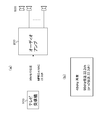
- FIG. 4B shows a display example on the display panel 217.
- a 22.2 channel MPEG-4 AAC compressed digital audio signal SA with a sampling frequency of 48 kHz is transmitted from the television receiver 100 to the audio amplifier 200 at 96 kHz. This is an example.
- the display of “48 kHz reproduction” in FIG. 4B indicates the sampling frequency of the output analog audio signal of each channel.
- “96 kHz transmission” or “x2 transmission” indicates the transmission frequency of the compressed digital audio signal SA.
- “96 kHz transmission” is a display using the transmission frequency indicated by the first metadata
- “x2 transmission” is a display using the ratio indicated by the third metadata.
- the display control unit 215 may directly control the display on the display panel 217.
- the CPU 212 and the display control unit 215 may be a single chip or a plurality of cores.
- the power supply unit 218 supplies power to each unit of the audio amplifier 200.
- the power supply unit 218 may be an AC power supply or a battery (storage battery, dry battery).
- the HDMI receiving unit 202b acquires video (image) data and audio data transmitted from the BD player 300 via the HDMI cable 620 to the HDMI terminal 201b.
- the video data and audio data are supplied to the HDMI transmission unit 202a via the video / graphic processing circuit 206 and the audio processing circuit 207, respectively, and the television receiver 100 via the HDMI cable 610 connected to the HDMI terminal 202a. Sent to.
- the high-speed bus interface 203a receives a partial TS transmitted from the television receiver 100 through a predetermined line of the HDMI cable 610 connected to the HDMI terminal 201a.
- the partial TS is supplied to the MPEG decoder 205 via the Ethernet interface 211.
- the MPEG decoder 205 the PES packet of the audio data constituting the partial TS is subjected to decoding processing to obtain an uncompressed digital audio signal of each channel of 2-channel or multi-channel.
- the uncompressed digital audio signal of each channel is supplied to the audio processing circuit 207 and subjected to necessary processing such as D / A conversion.
- necessary processing such as D / A conversion.
- the analog audio signal of each channel output from the audio processing circuit 207 is amplified and output to the audio output terminal 209. Therefore, 2-channel or multi-channel audio output can be obtained from the speaker system 500.
- the high-speed bus interface 203a receives an SPDIF signal including a predetermined number of channels of compressed digital audio signals SA transmitted from the television receiver 100 through a predetermined line of the HDMI cable 610 connected to the HDMI terminal 201a.
- the SPDIF signal is supplied to the SPDIF reception circuit 204.
- the SPDIF signal is processed to obtain a compressed digital audio signal SA having a predetermined number of channels.
- the compressed digital audio signal SA is supplied to the MPEG decoder 205.
- the MPEG decoder 205 performs a decoding process on the compressed digital audio signal SA to obtain an uncompressed digital audio signal of each channel of two channels or multi-channels.
- the uncompressed digital audio signal of each channel is supplied to the audio processing circuit 207 and subjected to necessary processing such as D / A conversion.
- necessary processing such as D / A conversion.
- the analog audio signal of each channel output from the audio processing circuit 207 is amplified and output to the audio output terminal 209. Therefore, 2-channel or multi-channel audio output can be obtained from the speaker system 500.
- the partial TS received by the high-speed bus interface 203a and supplied to the Ethernet interface 210 as described above is supplied as transmission data to the high-speed bus interface 203b. Therefore, these partial TS are transmitted to the BD player 300 via the HDMI cable 620 connected to the HDMI terminal 201b.
- FIG. 5 shows a configuration example of the BD player 300.
- the BD player 300 includes an HDMI terminal 301, an HDMI transmission unit 302, and a high-speed bus interface 303.
- the BD player 300 includes an internal bus 304, a CPU (Central Processing Unit) 305, a flash ROM (Read Only Memory) 306, an SDRAM (Synchronous Random Access Memory) 307, a display control unit 308, and a remote control reception. 309 and a remote control transmitter 310.
- a CPU Central Processing Unit
- flash ROM Read Only Memory
- SDRAM Synchronous Random Access Memory
- the BD player 300 includes a storage (recording) medium control interface 311, a BD (Blu-Ray-Disc) drive 312 a, an HDD (Hard disk drive) 312 b, an SSD (Solid State Drive) 312 c, and an Ethernet interface (Ethernet). I / F) 313 and a network terminal 314.
- the BD player 300 includes an MPEG (Moving Picture Picture Expert Group) decoder 315, a graphic generation circuit 316, a video output terminal 317, and an audio output terminal 318.
- MPEG Motion Picture Picture Expert Group
- the BD player 300 includes a panel drive circuit 319, a display panel 320, and a power supply unit 321.
- the CPU 305, flash ROM 306, SDRAM 307, storage medium control interface 311, Ethernet interface 313, and MPEG decoder 315 are connected to the internal bus 304.
- the CPU 305 controls the operation of each part of the BD player 300.
- the flash ROM 306 stores control software and data.
- the SDRAM 307 constitutes a work area for the CPU 305.
- the CPU 305 develops software and data read from the flash ROM 306 on the SDRAM 307 to activate the software, and controls each part of the BD player 300.
- the remote control receiving unit 309 receives a remote control signal (remote control code) transmitted from the remote control transmitter 310 and supplies it to the CPU 305.
- the CPU 305 controls each part of the BD player 300 according to the remote control code.
- the remote control unit is shown as the user instruction input unit.
- the user instruction input unit has other configurations, for example, a switch, a wheel, a touch panel unit for inputting an instruction by proximity / touch, a mouse It may be a keyboard, a gesture input unit for detecting an instruction input with a camera, a voice input unit for inputting an instruction by voice, or the like.
- the BD drive 312a records content data on a BD disc as a disc-shaped recording medium, or reproduces content data from the BD disc.
- the HDD 312b records content data or reproduces the content data.
- the SSD 312c records content data in a semiconductor memory such as a memory card or reproduces content data from the semiconductor memory.
- the BD drive 312a, the HDD 312b, and the SSD 312c are connected to the internal bus 304 via the storage medium control interface 311.
- a SATA interface is used as an interface for the BD drive 312a and the HDD 312b.
- a SATA interface or a PCIe interface is used as an interface for the SSD 312c.
- the MPEG decoder 315 performs decoding processing on the MPEG2 stream reproduced by the BD drive 312a, the HDD 312b, or the SSD 312c to obtain image and audio data.
- the graphic generation circuit 316 performs graphics data superimposition processing on the image data obtained by the MPEG decoder 315 as necessary.
- the video output terminal 317 outputs image data output from the graphic generation circuit 316.
- the audio output terminal 318 outputs the audio data obtained by the MPEG decoder 315.
- the panel drive circuit 319 drives the display panel 320 based on the video (image) data output from the graphic generation circuit 316.
- the display control unit 308 controls the display on the display panel 320 by controlling the graphics generation circuit 316 and the panel drive circuit 319.
- the display panel 320 includes, for example, an LCD (Liquid Crystal Display), a PDP (Plasma Display Panel) organic EL panel (Organic Electro-Luminescence Panel), or the like.
- the power supply unit 321 supplies power to each unit of the BD player 300.
- the power supply unit 321 may be an AC power supply or a battery (storage battery, dry battery).
- the HDMI transmission unit (HDMI source) 302 transmits baseband image (video) and audio data from the HDMI terminal 301 by communication conforming to HDMI.
- the high-speed bus interface 303 is an interface of a bidirectional communication path configured using a reserved line and an HPD line that configure an HDMI cable. Details of the HDMI transmission unit 302 will be described later.
- the high-speed bus interface 303 is inserted between the Ethernet interface 313 and the HDMI terminal 301.
- the high-speed bus interface 303 transmits the transmission data supplied from the CPU 305 from the HDMI terminal 301 to the counterpart device via the HDMI cable.
- the high-speed bus interface 303 supplies reception data received from the counterpart device from the HDMI cable via the HDMI terminal 301 to the CPU 305. Details of the high-speed bus interface 303 will be described later.
- the content data is input to the storage medium control interface 311 and recorded on the BD disc by the BD drive 312a, on the HDD 312b, or on the semiconductor memory by the SSD 312c.
- content data (MPEG stream) reproduced by the BD drive 312a, HDD 312b, or SSD 312c is supplied to the MPEG decoder 315 via the storage medium control interface 311.
- the MPEG decoder 315 performs decoding processing on the reproduced content data to obtain baseband image and audio data.
- the image data is output to the video output terminal 317 through the graphic generation circuit 316.
- Audio data is output to the audio output terminal 318.
- the image data obtained by the MPEG decoder 315 is supplied to the panel drive circuit 319 through the graphic generation circuit 316 according to the user operation, and the reproduced image is displayed on the display panel 320.
- the audio data obtained by the MPEG decoder 315 is supplied to a speaker (not shown) according to a user operation, and audio corresponding to the reproduced image is output.
- the image and audio data obtained by the MPEG decoder 315 are transmitted through the HDMI TMDS channel during the reproduction, the image and audio data are supplied to the HDMI transmission unit 302 and packed. The data is output from the HDMI transmission unit 302 to the HDMI terminal 301.
- the content data reproduced by the BD drive 312a, the HDD 312b, or the SSD 312c is transmitted to the network during reproduction, the content data is output to the network terminal 314 via the Ethernet interface 313.
- the content data reproduced by the BD drive 312a, the HDD 312b, or the SSD 312c is sent to the bidirectional communication path of the HDMI cable 620 during reproduction, the content data is transmitted via the high-speed bus interface 303.
- Output to terminal 301 Before outputting the image data, it may be transmitted after being encrypted using a copyright protection technology such as HDCP, DTCP, DTCP +, or the like.
- FIG. 6 shows a configuration example of the HDMI receiving unit 102 of the television receiver 100 and the HDMI transmitting unit 202a of the audio amplifier 200 in the AV system 10 of FIG. Note that the configuration example of the HDMI receiving unit 202b of the audio amplifier 200 and the HDMI transmitting unit 302 of the BD player 300 are the same, and thus the description thereof is omitted.
- the HDMI transmitting unit 202a is an effective image section that is a section obtained by removing a horizontal blanking period and a vertical blanking period from a section from a certain vertical synchronization signal to the next vertical synchronization signal (hereinafter referred to as “video field” as appropriate).
- video field a vertical synchronization signal
- active video period a differential signal of image data for one screen of baseband (uncompressed) is transmitted to the HDMI receiving unit 102 in one direction through a plurality of channels.
- the HDMI transmission unit 202a receives a plurality of differential signals corresponding to audio data and control packets (Control Packets) accompanying the image data, other auxiliary data, and the like in the horizontal blanking period and the vertical blanking period.
- the channel is transmitted to the HDMI receiving unit 102 in one direction.
- the HDMI transmission unit 202 a includes a source signal processing unit 71 and an HDMI transmitter 72.
- the source signal processing unit 71 is supplied with baseband uncompressed image (Video) and audio (Audio) data.
- the source signal processing unit 71 performs necessary processing on the supplied image and audio data and supplies the processed image and audio data to the HDMI transmitter 72. Further, the source signal processing unit 71 exchanges control information, status notification information (Control / Status), and the like with the HDMI transmitter 72 as necessary.
- the HDMI transmitter 72 converts the image data supplied from the source signal processing unit 71 into corresponding differential signals, and connects the HDMI cable 610 with the three TMDS channels # 0, # 1, and # 2, which are a plurality of channels. The data is transmitted in one direction to the HDMI receiving unit 102 connected via the network.
- auxiliary data auxiliary data supplied from the transmitter 72 and the source signal processing unit 71, the vertical synchronization signal (VSYNC), and the horizontal synchronization signal (HSYNC).
- the transmitter 72 transmits pixel clocks synchronized with image data transmitted through the three TMDS channels # 0, # 1, and # 2 to the HDMI receiving unit 102 connected via the HDMI cable 610 using the TMDS clock channel. Send.
- the HDMI receiving unit 102 receives a differential signal corresponding to image data transmitted in one direction from the HDMI transmitting unit 202a through a plurality of channels in the active video section, and also has a horizontal blanking period and a vertical blanking period.
- the differential signals corresponding to the auxiliary data and the control data transmitted from the HDMI transmitting unit 202a are received through a plurality of channels.
- the HDMI receiving unit 102 includes an HDMI receiver 81 and a sync signal processing unit 82.
- the HDMI receiver 81 is a TMDS channel # 0, # 1, # 2, and a differential signal corresponding to image data transmitted in one direction from the HDMI transmission unit 202a connected via the HDMI cable 610; A differential signal corresponding to auxiliary data and control data is received in synchronization with a pixel clock transmitted from the HDMI transmission unit 202a through the TMDS clock channel. Further, the HDMI receiver 81 converts the differential signal into corresponding image data, auxiliary data, and control data, and supplies them to the sync signal processing unit 82 as necessary.
- the sync signal processing unit 82 performs necessary processing on the data supplied from the HDMI receiver 81 and outputs the processed data. In addition, the sync signal processing unit 82 exchanges control information, status notification information (Control / Status), and the like with the HDMI receiver 81 as necessary.
- the HDMI transmission channel includes three TMDS channels for serially transmitting image data, auxiliary data, and control data in one direction in synchronization with the pixel clock from the HDMI transmitting unit 202a to the HDMI receiving unit 102.
- TMDS channels for serially transmitting image data, auxiliary data, and control data in one direction in synchronization with the pixel clock from the HDMI transmitting unit 202a to the HDMI receiving unit 102.
- # 0, # 1, and # 2 and a TMDS clock channel as a transmission channel for transmitting a pixel clock
- transmission channels called a DDC (Display Data Channel) 83 and a CEC line 84 are transmission channels called a DDC (Display Data Channel) 83 and a CEC line 84.
- the DDC 83 is composed of two lines (signal lines) (not shown) included in the HDMI cable 610, and the source device receives E-EDID (Enhanced Extended Extended Display Identification) from the sink device connected via the HDMI cable 610. Used for reading. That is, the sink device has an EDIDROM 85. The source device reads the E-EDID stored in the EDIDROM 85 from the sink device connected via the HDMI cable 610 via the DDC 83, and recognizes the settings and performance of the sink device based on the E-EDID. To do.
- E-EDID Enhanced Extended Extended Display Identification
- the CEC line 84 is composed of one line (not shown) included in the HDMI cable 610, and is used for bidirectional communication of control data between the source device and the sink device.
- the HDMI cable 610 includes a line 86 connected to a pin called HPD (Hot Plug Detect). The source device can detect the connection of the sink device using the line 86. Further, the HDMI cable 610 includes a line 87 used for supplying power from the source device to the sink device. Further, the HDMI cable 610 includes a reserved line 88.
- HPD Hot Plug Detect
- FIG. 7 shows sections of various transmission data when image data of horizontal ⁇ vertical 1920 pixels ⁇ 1080 lines is transmitted in the TMDS channel.
- a video field 24 Video Data Period
- a data island period 25 Data Island Period
- a video field in which transmission data is transmitted using the three TMDS channels of HDMI There are three types of sections, namely, control section 26 (Control26Period).
- the video field period is a period from a rising edge (Active Edge) of a certain vertical synchronizing signal to a rising edge of the next vertical synchronizing signal, and includes a horizontal blanking period 22 (Horizontal Blanking) and a vertical blanking period 23 ( Vertical Blanking) and an effective pixel section 21 (Active Video) that is a section obtained by removing the horizontal blanking period and the vertical blanking period from the video field section.
- the video data section 24 is assigned to the effective pixel section 21.
- data of 1920 pixels (pixels) ⁇ 1080 lines of effective pixels (Active Pixel) constituting uncompressed image data for one screen is transmitted.
- the data island period 25 and the control period 26 are assigned to the horizontal blanking period 22 and the vertical blanking period 23.
- auxiliary data (Auxiliary Data) is transmitted.
- the data island section 25 is allocated to a part of the horizontal blanking period 22 and the vertical blanking period 23.
- audio data packets that are not related to the control among the auxiliary data are transmitted.
- the control section 26 is allocated to other portions of the horizontal blanking period 22 and the vertical blanking period 23.
- vertical synchronization signals, horizontal synchronization signals, control packets, and the like, which are data related to control, of auxiliary data are transmitted.
- FIG. 8 shows a pin arrangement of the HDMI connector.
- This pin arrangement is an example of type A (type-A).
- TMDS Data # i + which is the differential signal of TMDS channel #i, and two lines that are TMDS Data # i- transmission lines are the pins to which TMDS Data # i + is assigned (pin number 1) , 4 and 7) and TMDS Data # i- assigned pins (pin numbers 3, 6 and 9).
- the CEC line 84 through which the CEC signal, which is control data, is transmitted is connected to the pin with the pin number 13, and the pin with the pin number 14 is a reserved pin.
- a line through which an SDA (Serial Data) signal such as E-EDID is transmitted is connected to a pin having a pin number of 16 and an SCL (Serial Clock) which is a clock signal used for synchronization when the SDA signal is transmitted and received.
- a line through which a signal is transmitted is connected to a pin having a pin number of 15.
- the above-described DDC 83 includes a line for transmitting the SDA signal and a line for transmitting the SCL signal.
- the HPD line 86 for detecting the connection of the sink device by the source device is connected to the pin having the pin number 19. Further, as described above, the power supply line 87 for supplying power is connected to the pin having the pin number 18.
- FIG. 9 shows a configuration example of the high-speed bus interface 103 of the television receiver 100 in the AV system 10 of FIG.
- the Ethernet interface 115 performs LAN (Local Area Network) communication, that is, transmission / reception of an Ethernet signal, using a transmission path configured by a pair of a reserved line and an HPD line among a plurality of lines constituting the HDMI cable 610.
- the SPDIF transmission circuit 104 transmits an SPDIF signal using the transmission path constituted by the above-described pair of lines.
- the television receiver 100 includes a LAN signal transmission circuit 441, a terminating resistor 442, AC coupling capacitors 443 and 444, a LAN signal reception circuit 445, a subtraction circuit 446, addition circuits 449 and 450, and an amplifier 451. These constitute the high-speed bus interface 103.
- the television receiver 100 includes a choke coil 461, a resistor 462, and a resistor 463 that constitute the plug connection transmission circuit 128.
- a series circuit of an AC coupling capacitor 443, a termination resistor 442, and an AC coupling capacitor 444 is connected between the 14-pin terminal 521 and the 19-pin terminal 522 of the HDMI terminal 101.
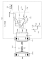
- a series circuit of a resistor 462 and a resistor 463 is connected between the power supply line (+5.0 V) and the ground line.
- a connection point between the resistor 462 and the resistor 463 is connected to a connection point Q4 between the 19-pin terminal 522 and the AC coupling capacitor 444 via the choke coil 461.
- connection point P3 between the AC coupling capacitor 443 and the termination resistor 442 is connected to the output side of the adder circuit 449 and to the positive input side of the LAN signal receiving circuit 445.
- a connection point P4 between the AC coupling capacitor 444 and the termination resistor 442 is connected to the output side of the adder circuit 450 and to the negative input side of the LAN signal receiving circuit 445.
- One input side of the addition circuit 449 is connected to the positive output side of the LAN signal transmission circuit 441, and the SPDIF signal output from the SPDIF transmission circuit 104 is supplied to the other input side of the addition circuit 449 via the amplifier 451. Is done. Further, one input side of the adder circuit 450 is connected to the negative output side of the LAN signal transmission circuit 441, and the SPDIF signal output from the SPDIF transmission circuit 104 is connected to the other input side of the addition circuit 450 via the amplifier 451. Supplied.
- a transmission signal (transmission data) SG417 is supplied from the Ethernet interface 115 to the input side of the LAN signal transmission circuit 441.
- the output signal SG418 of the LAN signal receiving circuit 445 is supplied to the positive terminal of the subtracting circuit 446, and the transmission signal SG417 is supplied to the negative terminal of the subtracting circuit 446.
- the transmission signal SG417 is subtracted from the output signal SG418 of the LAN signal receiving circuit 445 to obtain a reception signal (reception data) SG419.
- This reception signal SG419 becomes the LAN signal when a LAN signal (Ethernet signal) is transmitted as a differential signal via the reserved line and the HPD line.
- This reception signal SG419 is supplied to the Ethernet interface 115.
- FIG. 10 shows a configuration example of the high-speed bus interface 203a of the audio amplifier 200 in the AV system 10 of FIG.
- the Ethernet interface 210 performs LAN (Local Area Network) communication, that is, transmission and reception of an Ethernet signal, using a transmission path configured by a pair of lines of a reserved line and an HPD line among a plurality of lines constituting the HDMI cable 610.
- the SPDIF receiving circuit 204 receives the SPDIF signal using the transmission path constituted by the above-described pair of lines.
- the audio amplifier 200 includes a LAN signal transmission circuit 411, a termination resistor 412, AC coupling capacitors 413 and 414, a LAN signal reception circuit 415, a subtraction circuit 416, an addition circuit 419, and an amplifier 420. These constitute the high-speed bus interface 203a.
- the audio amplifier 200 includes a pull-down resistor 431, a resistor 432, a capacitor 433, and a comparator 434 that constitute a plug connection detection circuit 221.
- the resistor 432 and the capacitor 433 constitute a low-pass filter.
- a series circuit of an AC coupling capacitor 413, a termination resistor 412 and an AC coupling capacitor 414 is connected between the 14-pin terminal 511 and the 19-pin terminal 512 of the HDMI terminal 201a.
- a connection point P1 between the AC coupling capacitor 413 and the termination resistor 412 is connected to the positive output side of the LAN signal transmission circuit 411 and to the positive input side of the LAN signal reception circuit 415.
- connection point P2 between the AC coupling capacitor 414 and the termination resistor 412 is connected to the negative output side of the LAN signal transmission circuit 411 and to the negative input side of the LAN signal reception circuit 415.
- a transmission signal (transmission data) SG411 is supplied from the Ethernet interface 210 to the input side of the LAN signal transmission circuit 411.
- the output signal SG412 of the LAN signal receiving circuit 415 is supplied to the positive terminal of the subtraction circuit 416, and the transmission signal (transmission data) SG411 is supplied to the negative terminal of the subtraction circuit 416.
- the transmission signal SG411 is subtracted from the output signal SG412 of the LAN signal receiving circuit 415 to obtain a reception signal SG413.
- This reception signal SG413 is the LAN signal when a LAN signal (Ethernet signal) is transmitted as a differential signal via the reserve line and the HPD line.
- This reception signal SG413 is supplied to the Ethernet interface 210.
- connection point Q2 between the AC coupling capacitor 414 and the 19-pin terminal 512 is connected to the ground line through the pull-down resistor 431 and is connected to the ground line through a series circuit of the resistor 432 and the capacitor 433.
- the output signal of the low-pass filter obtained at the connection point between the resistor 432 and the capacitor 433 is supplied to one input terminal of the comparator 434.
- the output signal of the low-pass filter is compared with a reference voltage Vref2 (+1.4 V) supplied to the other input terminal.
- the output signal SG415 of the comparator 434 is supplied to a control unit (CPU) (not shown) of the audio amplifier 200.
- connection point P1 between the AC coupling capacitor 413 and the termination resistor 412 is connected to one input terminal of the adder circuit 419.
- connection point P2 between the AC coupling capacitor 414 and the termination resistor 412 is connected to the other input terminal of the adder circuit 419.
- the output signal of the adding circuit 419 is supplied to the SPDIF receiving circuit 115 via the amplifier 420.
- the output signal of the adding circuit 419 becomes the SPDIF signal when the SPDIF signal is transmitted as an in-phase signal via the reserved line and the HPD line.
- the high-speed bus interface 203b of the audio amplifier 200 has the same configuration as that of the high-speed bus interface 103 shown in FIG.
- the high-speed bus interface 303 of the BD player 300 has the same configuration as that of the high-speed bus interface 203a shown in FIG.
- FIG. 11 shows a frame configuration in the IEC 60958 standard.
- Each frame is composed of two subframes.
- the left channel signal is included in the first subframe
- the right channel signal is included in the second subframe.
- a preamble is provided at the head of the subframe, and “M” is assigned as the preamble to the left channel signal, and “W” is assigned as the preamble to the right channel signal.
- “B” indicating the start of a block is assigned to the leading preamble every 192 frames. That is, one block is composed of 192 frames.
- a block is a unit constituting a channel status described later.
- FIG. 12 shows a subframe configuration in the IEC 60958 standard.
- a subframe is composed of a total of 32 time slots from 0th to 31st.
- the 0th to 3rd time slots indicate a preamble (Sync preamble).
- This preamble indicates one of “M”, “W”, and “B” in order to distinguish the left and right channels and to indicate the start position of the block as described above.
- the 4th to 27th time slots are main data fields, and when the 24-bit code range is adopted, the whole represents audio data.
- the 8th to 27th time slots represent audio data (Audio (sample word).
- the fourth to seventh time slots can be used as additional information (Auxiliary sample bits).
- the illustrated example shows the latter case.
- the 28th time slot is a validity flag (Validity flag) of the main data field.
- the 29th time slot represents one bit of user data (User data).
- a series of user data can be constructed by accumulating the 29th time slot across each frame.
- This user data message is configured in units of 8-bit information units (IU: Information Unit), and one message includes 3 to 129 information units.
- [0] There can be 0 to 8 bits of “0” between information units.
- the head of the information unit is identified by the start bit “1”.
- the first seven information units in the message are reserved, and the user can set arbitrary information in the eighth and subsequent information units. Messages are divided by “0” of 8 bits or more.
- the 30th time slot represents one bit of the channel status (Channel status).
- a series of channel statuses can be constructed by accumulating the 30th time slot for each block across each frame.
- the head position of the block is indicated by the “B” preamble (0th to 3rd time slots) as described above.
- the 31st time slot is a parity bit. This parity bit is added so that the number of “0” and “1” included in the fourth to 31st time slots is an even number.
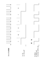
- FIG. 13 shows a signal modulation method according to the IEC 60958 standard.
- Bi-phase mark modulation is performed on the 4th to 31st time slots excluding the preamble in the subframe.
- a clock that is twice as fast as the original signal (source coding) is used. If the clock cycle of the original signal is divided into the first half and the second half, the output of the biphase mark modulation is always inverted at the edge of the first half clock cycle. Further, at the edge of the second half clock cycle, the signal is inverted when the original signal indicates “1”, and is not inverted when the original signal indicates “0”. As a result, the clock component in the original signal can be extracted from the biphase mark modulated signal.
- FIG. 14 shows channel coding of a preamble in the IEC 60958 standard.
- the fourth to 31st time slots of the subframe are biphase mark modulated.
- the preambles in the 0th to 3rd time slots are handled as bit patterns synchronized with the double speed clock, not the normal biphase mark modulation. That is, by assigning 2 bits to each time slot of the 0th to 3rd time slots, an 8-bit pattern as shown in the figure is obtained.
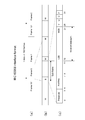
- FIG. 15 shows the IEC 60958 interface format (IEC 60958 interface format).
- FIG. 15A shows a frame configuration. One block is composed of 192 frames, and the blocks are continuous.
- FIG. 15B shows that each frame is composed of two subframes.
- a preamble is provided at the head of the subframe, and “B” representing the start of the block is given to the preamble of the head subframe of the block. Then, “W” and “M” are alternately given to the leading preamble of each subsequent subframe.
- FIG. 15C shows a subframe configuration.
- the bit stream of the compressed digital audio signal SA is divided and sequentially inserted into the 12th to 27th time slots of each subframe.
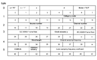
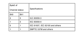
- FIG. 16 schematically shows a channel status format in the case of an SPDIF signal including a compressed digital audio signal SA having a predetermined number of channels.
- the entire channel status consists of the 0th to 23rd bytes, but in the example shown, only the 0th to 5th bytes are shown.
- the first metadata that is, metadata “IEC 60958“ Frame Rate ”indicating the transmission frequency of the compressed digital audio signal is inserted.
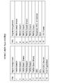
- FIG. 18 shows the correspondence between the bit values of the 24th to 27th bits and the bit values of the 30th to 31st bits and the transmission frequency indicated by the bit values. For example, when the bit values of the 24th to 27th bits are assigned to “0100b”, it is indicated that the transmission frequency is 48 kHz. For example, when the bit values of the 24th to 27th bits are assigned to “0101b”, it is indicated that the transmission frequency is 96 kHz.
- IEC 60958-Frame Rate is a basic frequency that the PLL locks when receiving an IEC 60958-3 digital audio signal (SPDF signal), and is actually 128 times higher than that of metadata. That is, when the transmission frequency indicated by “IECI60958 Frame Rate” is 48 kHz, the PLL actually locks at 6.144 MHz. This is defined in IEC 60958-1.
- the compressed digital audio signal defined in IEC 61937 has a maximum 32-bit payload allocated to this “IEC 60958” Frame “Rate”. Therefore, when “IEC 60958” Frame “Rate” is 48 kHz, the compression is about 1.5 Mbps at maximum. Digital audio signals can be transmitted. Actually, overhead such as a packet header is required, and is defined in IEC 6937-1.
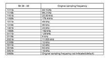
- the second metadata that is, metadata “Original” sampling frequency indicating the sampling frequency used when the uncompressed digital audio signal of each channel is converted into an analog signal.
- FIG. 19 shows the correspondence between the bit values of the 36th to 39th bits and the sampling frequency indicated thereby. For example, when the bit values of the 36th to 39th bits are assigned as “1011b”, it indicates that the sampling frequency is 48 kHz.
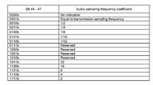
- the third metadata that is, metadata “Audio sampling frequency” indicating the ratio of the transmission frequency to the sampling frequency is inserted into the 44th to 47th bits.
- FIG. 20 shows a correspondence relationship between the bit values of the 44th to 47th bits and the ratios indicated thereby. For example, when the bit values of the 44th to 47th bits are assigned as “1111b”, it is indicated that the ratio is 2.
- next-generation TV broadcasting it is planned to broadcast 22.2 channels of MPEG-4 AAC compressed digital audio signals at a maximum of 1.9 Mbps at 48 kHz sampling.
- the television receiver 100 indicates the transmission frequency of the compressed digital audio signal in the compressed digital audio signal of the predetermined number of channels included in the SPDIF signal transmitted to the audio amplifier 200.
- First metadata second metadata indicating a sampling frequency used when converting an uncompressed digital audio signal of each channel into an analog signal
- third metadata indicating a ratio of the transmission frequency to the sampling frequency Append.
- transmission of a compressed digital audio signal having a high data rate can be performed satisfactorily. That is, transmission at a transmission rate different from the sampling frequency is possible, and on the receiving side, correct audio reproduction is possible at the original sampling frequency different from the transmission rate, and the audio frequency band that is actually reproduced for the user Can be specified.
- the audio amplifier 200 performs processing related to the compressed digital audio signal included in the SPDIF signal, and sets the transmission frequency of the compressed digital audio signal added to the compressed digital audio signal.
- First metadata indicating, second metadata indicating a sampling frequency used when converting the uncompressed digital audio signal of each channel into an analog signal, and third metadata indicating a ratio of the transmission frequency to the sampling frequency Based on. Therefore, processing related to the compressed digital audio signal, for example, decoding processing, processing for converting to an analog signal, processing for clearly indicating the playback audio frequency band to the user, and the like can be appropriately performed.
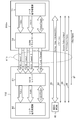
- FIG. 21 shows a configuration example of the AV system 10A when an optical cable is used as the IEC 60958 transmission line.
- the television receiver 100 includes an optical interface 129
- the audio amplifier 200 includes an optical interface 222.
- the SPDIF signal output from the SPDIF transmission circuit 104 of the television receiver 100 is transmitted to the SPDIF reception circuit 204 of the audio amplifier 200 via the optical interface 129, the optical cable 630, and the optical interface 222.
- the SPDIF signal (IEC 60958 signal) is mapped to an audio sample packet (audio sample packet) and transmitted in the same forward direction as video transmission.
- the IEC 60958 transmission path an example in which an IEC 618883-6 transmission path, an MHL transmission path, a display port transmission path (DP transmission path), or the like can be considered.
- the SPDIF signal (IEC 60958 signal) is mapped to an audio sample packet (audio sample packet) and transmitted in the same forward direction as the video transmission.
- the compressed digital audio signal SA included in the SPDIF signal is acquired from the broadcast signal.
- the compressed digital audio signal SA is reproduced and acquired from a recording medium.
- a transmission apparatus comprising: a transmission unit configured to transmit the compressed digital audio signal to which each metadata is added to an external device via a predetermined transmission path.
- the transmission unit sequentially transmits the compressed digital audio signal for each unit data,
- the metadata adding unit The transmission apparatus according to (1), wherein the metadata is added using a predetermined bit area of a channel status of each block configured by a predetermined number of the unit data.
- the transmission apparatus according to (1) or (2), wherein the encoding method of the compressed digital audio signal is MPEG-4 AAC.
- the transmission device according to any one of (1) to (4), wherein the predetermined transmission path is a coaxial cable, an optical cable, an Ethernet (IEC 61883-6) cable, an HDMI cable, an MHL cable, or a display port cable. .
- the acquisition unit according to any one of (1) to (5), further including an acquisition unit that acquires the compressed digital audio signal from a broadcast signal or reproduces and acquires the compressed digital audio signal from a recording medium. Transmitter device.
- a transmission method comprising: a transmission step of transmitting a compressed digital audio signal to which each of the metadata is added to an external device via a predetermined transmission path by a transmission unit.
- a receiving unit that receives a predetermined number of channels of compressed digital audio signals from an external device via a predetermined transmission path;
- the compressed digital audio signal includes first metadata indicating the transmission frequency of the compressed digital audio signal, and second sampling frequency used when converting the uncompressed digital audio signal of each channel into an analog signal.
- Third metadata indicating the ratio of the metadata and the transmission frequency to the sampling frequency is added,
- a receiving apparatus comprising: a processing unit that performs a process related to the compressed digital audio signal based on at least one of the metadata.
- the processing unit The PLL is locked to a frequency corresponding to the transmission frequency indicated by the first metadata, the compressed digital audio signal is decoded using a clock signal having a frequency locked by the PLL, and the predetermined number of channels
- the receiving device (8), wherein an uncompressed digital audio signal of each channel is obtained.
- the processing unit The uncompressed digital audio signal of each channel obtained by decoding the compressed digital audio signal is converted into an analog signal at the sampling frequency indicated by the second metadata and output (8) or The receiving device according to (9).
- (11) The processing unit The receiving device according to any one of (8) to (10), wherein the sampling frequency indicated by the second metadata is displayed on the display unit as the sampling frequency of the output analog audio signal of each channel.
- the processing unit Using the transmission frequency indicated by the first metadata or the ratio indicated by the third metadata, a display indicating the transmission frequency of the compressed digital audio signal is displayed on the display unit (8) to (11 ). (13) The processing unit The ratio of the transmission frequency indicated by the first metadata to the sampling frequency indicated by the second metadata is compared with the ratio indicated by the third metadata, and the first metadata or the first metadata is compared. The receiving apparatus according to any one of (8) to (13), wherein an error in the second metadata is detected. (14) The reception unit sequentially receives the compressed digital audio signal for each unit data, Each metadata is added to the compressed digital audio signal using a predetermined bit area of a channel status of each block composed of a predetermined number of the unit data.
- the receiving apparatus in any one.
- the receiving device according to any one of (8) to (14), wherein the predetermined transmission path is a coaxial cable, an optical cable, an Ethernet (IEC 61883-6) cable, an HDMI cable, an MHL cable, or a display port cable.
- the reception unit includes a reception step of receiving a predetermined number of channels of compressed digital audio signals from an external device via a predetermined transmission path,
- the compressed digital audio signal includes first metadata indicating the transmission frequency of the compressed digital audio signal, and second sampling frequency used when converting the uncompressed digital audio signal of each channel into an analog signal.
- Third metadata indicating the ratio of the metadata and the transmission frequency to the sampling frequency is added,
- a receiving method comprising a processing step of performing a process related to the compressed digital audio signal based on at least one of the metadata.
- DESCRIPTION OF SYMBOLS 10 ... AV system 100 ... Television receiver 101 ... HDMI terminal 102 ... HDMI receiving part 103 ... High speed bus interface 104 ... SPDIF transmission circuit 105 ... Antenna terminal 106 ... Digital broadcast tuner 107: MPEG decoder 108 ... Video signal processing circuit 109 ... Graphic generation circuit 110 ... Panel drive circuit 111 ... Display panel 112 ... Audio signal processing circuit 113 ... Audio amplifier circuit 114 ... Speaker 115 ... Ethernet interface 116 ... Network terminal 120 ... Internal bus 121 ... CPU 122 ... Flash ROM 123 ... DRAM 124 ... Display control unit 125 ... Remote control receiving unit 126 ... Remote control transmitter 127 ... Power supply unit 128 ...
- Plug connection transmission circuit 200 ... Audio amplifiers 201a, 201b ... HDMI terminal 202a ... HDMI transmission unit 202b ... HDMI reception unit 203a. 203b ... High-speed bus interface 204 ... SPDIF receiving circuit 205 ... MPEG decoder 206 ... Video / graphic processing circuit 207 ... Audio processing circuit 208 ... Audio amplification circuit 209 ... Audio output terminal 210: Ethernet interface 211 ... Internal bus 212 ... CPU 213: Flash ROM 214 ... DRAM 215: Display control unit 216: Panel drive circuit 217 ... Display panel 218 ... Power supply unit 219 ... Remote control reception unit 220 ... Remote control transmitter 221 ... Plug connection detection circuit 300 ..BD player 301 ...
- HDMI terminal 302 ... HDMI transmission unit 303 ... high speed bus interface 304 ... internal bus 305 ... CPU 306 ... Flash ROM 307 ... SDRAM 308: Display control unit 309: Remote control receiving unit 310 ... Remote control transmitter 311 ... Storage medium control interface 312a ... BD drive 312b ... HDD 312c ... SSD 313: Ethernet interface 314 Network terminal 315 MPEG decoder 316 Graphic generation circuit 317 Video output terminal 318 Audio output terminal 319 Panel drive circuit 320 Display panel 321 ... Power supply unit 400 ... Receiving antenna 500 ... Speaker system 610,620 ... HDMI cable 630 ... Optical cable
Landscapes
- Engineering & Computer Science (AREA)
- Multimedia (AREA)
- Signal Processing (AREA)
- Physics & Mathematics (AREA)
- Human Computer Interaction (AREA)
- Audiology, Speech & Language Pathology (AREA)
- Health & Medical Sciences (AREA)
- Computational Linguistics (AREA)
- Acoustics & Sound (AREA)
- Computer Networks & Wireless Communication (AREA)
- Theoretical Computer Science (AREA)
- Mathematical Physics (AREA)
- Two-Way Televisions, Distribution Of Moving Picture Or The Like (AREA)
Abstract
La présente invention permet d'effectuer de manière satisfaisante la transmission de données à haut débit d'un signal audio numérique compressé. Des premier, deuxième et troisième éléments de métadonnées sont annexés à des signaux audio numériques compressés d'un nombre prescrit de canaux. Le premier élément de métadonnées indique la fréquence de transmission du signal audio compressé. Le deuxième élément de métadonnées indique la fréquence d'échantillonnage à utiliser lors de la conversion des signaux audio numériques non-compressés des canaux en signaux analogiques. Le troisième élément de métadonnées indique le rapport de la fréquence de transmission à la fréquence d'échantillonnage. Les signaux audio numériques compressés, avec les éléments de métadonnées annexés, sont envoyés à un dispositif externe par l'intermédiaire d'un chemin de transmission prescrit.
Priority Applications (2)
| Application Number | Priority Date | Filing Date | Title |
|---|---|---|---|
| JP2017528616A JP6863282B2 (ja) | 2015-07-10 | 2016-07-05 | 受信装置および受信方法 |
| US15/741,376 US10593337B2 (en) | 2015-07-10 | 2016-07-05 | Transmission apparatus, transmission method, reception apparatus, and reception method |
Applications Claiming Priority (2)
| Application Number | Priority Date | Filing Date | Title |
|---|---|---|---|
| JP2015138212 | 2015-07-10 | ||
| JP2015-138212 | 2015-07-10 |
Publications (1)
| Publication Number | Publication Date |
|---|---|
| WO2017010358A1 true WO2017010358A1 (fr) | 2017-01-19 |
Family
ID=57757002
Family Applications (1)
| Application Number | Title | Priority Date | Filing Date |
|---|---|---|---|
| PCT/JP2016/069954 Ceased WO2017010358A1 (fr) | 2015-07-10 | 2016-07-05 | Dispositif d'envoi, procédé d'envoi, dispositif et procédé de réception |
Country Status (3)
| Country | Link |
|---|---|
| US (1) | US10593337B2 (fr) |
| JP (1) | JP6863282B2 (fr) |
| WO (1) | WO2017010358A1 (fr) |
Cited By (5)
| Publication number | Priority date | Publication date | Assignee | Title |
|---|---|---|---|---|
| JP2019161660A (ja) * | 2019-05-07 | 2019-09-19 | 東芝映像ソリューション株式会社 | 放送送信装置及び放送送信方法 |
| WO2019225448A1 (fr) * | 2018-05-23 | 2019-11-28 | ソニー株式会社 | Dispositif d'émission, procédé d'émission, dispositif de réception et procédé de réception |
| WO2019225449A1 (fr) * | 2018-05-23 | 2019-11-28 | ソニー株式会社 | Dispositif d'émission, procédé d'émission, dispositif de réception et procédé de réception |
| WO2020137767A1 (fr) * | 2018-12-26 | 2020-07-02 | ソニー株式会社 | Dispositif de transmission, procédé de transmission, dispositif de réception et procédé de réception |
| WO2020175249A1 (fr) * | 2019-02-27 | 2020-09-03 | ソニー株式会社 | Dispositif de transmission, procédé de transmission, dispositif de réception et procédé de réception |
Families Citing this family (4)
| Publication number | Priority date | Publication date | Assignee | Title |
|---|---|---|---|---|
| WO2021039189A1 (fr) * | 2019-08-30 | 2021-03-04 | ソニー株式会社 | Dispositif de transmission, procédé de transmission, dispositif de réception et procédé de réception |
| EP3857919B1 (fr) | 2019-12-02 | 2022-05-18 | Dolby Laboratories Licensing Corporation | Procédés et appareil de conversion d'un signal audio basé sur un canal à un signal audio basé sur un objet |
| US20240394009A1 (en) * | 2023-05-22 | 2024-11-28 | Avermedia Technologies, Inc. | Audio conversion method and device |
| CN119316549B (zh) * | 2024-12-16 | 2025-04-01 | 杭州海康威视数字技术股份有限公司 | 一种音频传输方法、视频处理设备及数据传输系统 |
Citations (1)
| Publication number | Priority date | Publication date | Assignee | Title |
|---|---|---|---|---|
| WO2009139386A1 (fr) * | 2008-05-12 | 2009-11-19 | ソニー株式会社 | Circuit d'interface |
Family Cites Families (2)
| Publication number | Priority date | Publication date | Assignee | Title |
|---|---|---|---|---|
| US7809346B2 (en) * | 2005-04-29 | 2010-10-05 | Texas Instruments Incorporated | Digital audio receiver with reduced AM interference |
| US9678707B2 (en) * | 2015-04-10 | 2017-06-13 | Sonos, Inc. | Identification of audio content facilitated by playback device |
-
2016
- 2016-07-05 WO PCT/JP2016/069954 patent/WO2017010358A1/fr not_active Ceased
- 2016-07-05 US US15/741,376 patent/US10593337B2/en active Active
- 2016-07-05 JP JP2017528616A patent/JP6863282B2/ja active Active
Patent Citations (1)
| Publication number | Priority date | Publication date | Assignee | Title |
|---|---|---|---|---|
| WO2009139386A1 (fr) * | 2008-05-12 | 2009-11-19 | ソニー株式会社 | Circuit d'interface |
Non-Patent Citations (1)
| Title |
|---|
| "IEC 60958-3 AMENDMENT 1", October 2009 (2009-10-01), Retrieved from the Internet <URL:http://www.meconinfo.co.in/IECPDF/pdf/ iec60958-3-amdl%7Bed3.0%7Den.pdf> * |
Cited By (10)
| Publication number | Priority date | Publication date | Assignee | Title |
|---|---|---|---|---|
| WO2019225448A1 (fr) * | 2018-05-23 | 2019-11-28 | ソニー株式会社 | Dispositif d'émission, procédé d'émission, dispositif de réception et procédé de réception |
| WO2019225449A1 (fr) * | 2018-05-23 | 2019-11-28 | ソニー株式会社 | Dispositif d'émission, procédé d'émission, dispositif de réception et procédé de réception |
| US11942103B2 (en) | 2018-05-23 | 2024-03-26 | Sony Corporation | Transmission apparatus, transmission method, reception apparatus, and reception method for transmitting and receiving an audio signal including a mixed signal simultaneously transmitted by mixing a compressed audio signal and a linear pulse code modulation signal |
| WO2020137767A1 (fr) * | 2018-12-26 | 2020-07-02 | ソニー株式会社 | Dispositif de transmission, procédé de transmission, dispositif de réception et procédé de réception |
| JPWO2020137767A1 (ja) * | 2018-12-26 | 2021-11-11 | ソニーグループ株式会社 | 送信装置、送信方法、受信装置および受信方法 |
| JP7396300B2 (ja) | 2018-12-26 | 2023-12-12 | ソニーグループ株式会社 | 送信装置、送信方法、受信装置および受信方法 |
| US12003886B2 (en) | 2018-12-26 | 2024-06-04 | Sony Group Corporation | Transmission device, transmission method, reception device, and reception method |
| WO2020175249A1 (fr) * | 2019-02-27 | 2020-09-03 | ソニー株式会社 | Dispositif de transmission, procédé de transmission, dispositif de réception et procédé de réception |
| JP7452526B2 (ja) | 2019-02-27 | 2024-03-19 | ソニーグループ株式会社 | 送信装置、送信方法、受信装置および受信方法 |
| JP2019161660A (ja) * | 2019-05-07 | 2019-09-19 | 東芝映像ソリューション株式会社 | 放送送信装置及び放送送信方法 |
Also Published As
| Publication number | Publication date |
|---|---|
| JPWO2017010358A1 (ja) | 2018-05-10 |
| JP6863282B2 (ja) | 2021-04-21 |
| US10593337B2 (en) | 2020-03-17 |
| US20190005968A1 (en) | 2019-01-03 |
Similar Documents
| Publication | Publication Date | Title |
|---|---|---|
| JP6863282B2 (ja) | 受信装置および受信方法 | |
| US8230118B2 (en) | Interface circuit and video apparatus | |
| EP2211545B1 (fr) | Appareil de reproduction, appareil d'affichage, procédé de reproduction et procédé d'affichage | |
| EP2362643B1 (fr) | Système de reproduction de contenu, appareil de réception de contenu, appareil de reproduction sonore, procédé de reproduction de contenu et programme | |
| US9667369B2 (en) | Interface circuit for transmitting and receiving digital signals between devices | |
| JP4752865B2 (ja) | インターフェース回路 | |
| JP6809470B2 (ja) | 送信装置、送信方法、受信装置および受信方法 | |
| JP6589875B2 (ja) | 送信装置、送信方法、受信装置および受信方法 | |
| JP6973403B2 (ja) | 送信装置、送信方法、受信装置および受信方法 | |
| JP6669071B2 (ja) | 送信装置、送信方法、受信装置および受信方法 | |
| JP6973402B2 (ja) | 送信装置、送信方法、受信装置および受信方法 | |
| WO2019225449A1 (fr) | Dispositif d'émission, procédé d'émission, dispositif de réception et procédé de réception | |
| WO2016163327A1 (fr) | Dispositif de transmission, procédé de transmission, dispositif de réception, et procédé de réception | |
| JP4596085B2 (ja) | インターフェース回路 |
Legal Events
| Date | Code | Title | Description |
|---|---|---|---|
| 121 | Ep: the epo has been informed by wipo that ep was designated in this application |
Ref document number: 16824338 Country of ref document: EP Kind code of ref document: A1 |
|
| ENP | Entry into the national phase |
Ref document number: 2017528616 Country of ref document: JP Kind code of ref document: A |
|
| NENP | Non-entry into the national phase |
Ref country code: DE |
|
| 122 | Ep: pct application non-entry in european phase |
Ref document number: 16824338 Country of ref document: EP Kind code of ref document: A1 |