WO2017010388A1 - Dispositif de conversion de puissance - Google Patents
Dispositif de conversion de puissance Download PDFInfo
- Publication number
- WO2017010388A1 WO2017010388A1 PCT/JP2016/070076 JP2016070076W WO2017010388A1 WO 2017010388 A1 WO2017010388 A1 WO 2017010388A1 JP 2016070076 W JP2016070076 W JP 2016070076W WO 2017010388 A1 WO2017010388 A1 WO 2017010388A1
- Authority
- WO
- WIPO (PCT)
- Prior art keywords
- voltage
- power converter
- converter
- power
- current
- Prior art date
- Legal status (The legal status is an assumption and is not a legal conclusion. Google has not performed a legal analysis and makes no representation as to the accuracy of the status listed.)
- Ceased
Links
Images


Classifications
-
- H—ELECTRICITY
- H02—GENERATION; CONVERSION OR DISTRIBUTION OF ELECTRIC POWER
- H02M—APPARATUS FOR CONVERSION BETWEEN AC AND AC, BETWEEN AC AND DC, OR BETWEEN DC AND DC, AND FOR USE WITH MAINS OR SIMILAR POWER SUPPLY SYSTEMS; CONVERSION OF DC OR AC INPUT POWER INTO SURGE OUTPUT POWER; CONTROL OR REGULATION THEREOF
- H02M7/00—Conversion of AC power input into DC power output; Conversion of DC power input into AC power output
- H02M7/42—Conversion of DC power input into AC power output without possibility of reversal
- H02M7/44—Conversion of DC power input into AC power output without possibility of reversal by static converters
- H02M7/48—Conversion of DC power input into AC power output without possibility of reversal by static converters using discharge tubes with control electrode or semiconductor devices with control electrode
- H02M7/483—Converters with outputs that each can have more than two voltages levels
- H02M7/4835—Converters with outputs that each can have more than two voltages levels comprising two or more cells, each including a switchable capacitor, the capacitors having a nominal charge voltage which corresponds to a given fraction of the input voltage, and the capacitors being selectively connected in series to determine the instantaneous output voltage
-
- H—ELECTRICITY
- H02—GENERATION; CONVERSION OR DISTRIBUTION OF ELECTRIC POWER
- H02M—APPARATUS FOR CONVERSION BETWEEN AC AND AC, BETWEEN AC AND DC, OR BETWEEN DC AND DC, AND FOR USE WITH MAINS OR SIMILAR POWER SUPPLY SYSTEMS; CONVERSION OF DC OR AC INPUT POWER INTO SURGE OUTPUT POWER; CONTROL OR REGULATION THEREOF
- H02M1/00—Details of apparatus for conversion
- H02M1/08—Circuits specially adapted for the generation of control voltages for semiconductor devices incorporated in static converters
- H02M1/084—Circuits specially adapted for the generation of control voltages for semiconductor devices incorporated in static converters using a control circuit common to several phases of a multi-phase system
- H02M1/0845—Circuits specially adapted for the generation of control voltages for semiconductor devices incorporated in static converters using a control circuit common to several phases of a multi-phase system digitally controlled (or with digital control)
-
- H—ELECTRICITY
- H02—GENERATION; CONVERSION OR DISTRIBUTION OF ELECTRIC POWER
- H02M—APPARATUS FOR CONVERSION BETWEEN AC AND AC, BETWEEN AC AND DC, OR BETWEEN DC AND DC, AND FOR USE WITH MAINS OR SIMILAR POWER SUPPLY SYSTEMS; CONVERSION OF DC OR AC INPUT POWER INTO SURGE OUTPUT POWER; CONTROL OR REGULATION THEREOF
- H02M1/00—Details of apparatus for conversion
- H02M1/12—Arrangements for reducing harmonics from AC input or output
-
- H—ELECTRICITY
- H02—GENERATION; CONVERSION OR DISTRIBUTION OF ELECTRIC POWER
- H02M—APPARATUS FOR CONVERSION BETWEEN AC AND AC, BETWEEN AC AND DC, OR BETWEEN DC AND DC, AND FOR USE WITH MAINS OR SIMILAR POWER SUPPLY SYSTEMS; CONVERSION OF DC OR AC INPUT POWER INTO SURGE OUTPUT POWER; CONTROL OR REGULATION THEREOF
- H02M1/00—Details of apparatus for conversion
- H02M1/32—Means for protecting converters other than automatic disconnection
-
- H—ELECTRICITY
- H02—GENERATION; CONVERSION OR DISTRIBUTION OF ELECTRIC POWER
- H02M—APPARATUS FOR CONVERSION BETWEEN AC AND AC, BETWEEN AC AND DC, OR BETWEEN DC AND DC, AND FOR USE WITH MAINS OR SIMILAR POWER SUPPLY SYSTEMS; CONVERSION OF DC OR AC INPUT POWER INTO SURGE OUTPUT POWER; CONTROL OR REGULATION THEREOF
- H02M7/00—Conversion of AC power input into DC power output; Conversion of DC power input into AC power output
- H02M7/02—Conversion of AC power input into DC power output without possibility of reversal
- H02M7/04—Conversion of AC power input into DC power output without possibility of reversal by static converters
- H02M7/12—Conversion of AC power input into DC power output without possibility of reversal by static converters using discharge tubes with control electrode or semiconductor devices with control electrode
- H02M7/21—Conversion of AC power input into DC power output without possibility of reversal by static converters using discharge tubes with control electrode or semiconductor devices with control electrode using devices of a triode or transistor type requiring continuous application of a control signal
- H02M7/217—Conversion of AC power input into DC power output without possibility of reversal by static converters using discharge tubes with control electrode or semiconductor devices with control electrode using devices of a triode or transistor type requiring continuous application of a control signal using semiconductor devices only
- H02M7/219—Conversion of AC power input into DC power output without possibility of reversal by static converters using discharge tubes with control electrode or semiconductor devices with control electrode using devices of a triode or transistor type requiring continuous application of a control signal using semiconductor devices only in a bridge configuration
-
- H—ELECTRICITY
- H02—GENERATION; CONVERSION OR DISTRIBUTION OF ELECTRIC POWER
- H02M—APPARATUS FOR CONVERSION BETWEEN AC AND AC, BETWEEN AC AND DC, OR BETWEEN DC AND DC, AND FOR USE WITH MAINS OR SIMILAR POWER SUPPLY SYSTEMS; CONVERSION OF DC OR AC INPUT POWER INTO SURGE OUTPUT POWER; CONTROL OR REGULATION THEREOF
- H02M1/00—Details of apparatus for conversion
- H02M1/0067—Converter structures employing plural converter units, other than for parallel operation of the units on a single load
- H02M1/007—Plural converter units in cascade
-
- H—ELECTRICITY
- H02—GENERATION; CONVERSION OR DISTRIBUTION OF ELECTRIC POWER
- H02M—APPARATUS FOR CONVERSION BETWEEN AC AND AC, BETWEEN AC AND DC, OR BETWEEN DC AND DC, AND FOR USE WITH MAINS OR SIMILAR POWER SUPPLY SYSTEMS; CONVERSION OF DC OR AC INPUT POWER INTO SURGE OUTPUT POWER; CONTROL OR REGULATION THEREOF
- H02M1/00—Details of apparatus for conversion
- H02M1/0083—Converters characterised by their input or output configuration
- H02M1/0085—Partially controlled bridges
-
- H—ELECTRICITY
- H02—GENERATION; CONVERSION OR DISTRIBUTION OF ELECTRIC POWER
- H02M—APPARATUS FOR CONVERSION BETWEEN AC AND AC, BETWEEN AC AND DC, OR BETWEEN DC AND DC, AND FOR USE WITH MAINS OR SIMILAR POWER SUPPLY SYSTEMS; CONVERSION OF DC OR AC INPUT POWER INTO SURGE OUTPUT POWER; CONTROL OR REGULATION THEREOF
- H02M1/00—Details of apparatus for conversion
- H02M1/08—Circuits specially adapted for the generation of control voltages for semiconductor devices incorporated in static converters
- H02M1/084—Circuits specially adapted for the generation of control voltages for semiconductor devices incorporated in static converters using a control circuit common to several phases of a multi-phase system
-
- H—ELECTRICITY
- H02—GENERATION; CONVERSION OR DISTRIBUTION OF ELECTRIC POWER
- H02M—APPARATUS FOR CONVERSION BETWEEN AC AND AC, BETWEEN AC AND DC, OR BETWEEN DC AND DC, AND FOR USE WITH MAINS OR SIMILAR POWER SUPPLY SYSTEMS; CONVERSION OF DC OR AC INPUT POWER INTO SURGE OUTPUT POWER; CONTROL OR REGULATION THEREOF
- H02M1/00—Details of apparatus for conversion
- H02M1/32—Means for protecting converters other than automatic disconnection
- H02M1/325—Means for protecting converters other than automatic disconnection with means for allowing continuous operation despite a fault, i.e. fault tolerant converters
-
- H—ELECTRICITY
- H02—GENERATION; CONVERSION OR DISTRIBUTION OF ELECTRIC POWER
- H02M—APPARATUS FOR CONVERSION BETWEEN AC AND AC, BETWEEN AC AND DC, OR BETWEEN DC AND DC, AND FOR USE WITH MAINS OR SIMILAR POWER SUPPLY SYSTEMS; CONVERSION OF DC OR AC INPUT POWER INTO SURGE OUTPUT POWER; CONTROL OR REGULATION THEREOF
- H02M1/00—Details of apparatus for conversion
- H02M1/42—Circuits or arrangements for compensating for or adjusting power factor in converters or inverters
- H02M1/4208—Arrangements for improving power factor of AC input
- H02M1/4216—Arrangements for improving power factor of AC input operating from a three-phase input voltage
-
- H—ELECTRICITY
- H02—GENERATION; CONVERSION OR DISTRIBUTION OF ELECTRIC POWER
- H02M—APPARATUS FOR CONVERSION BETWEEN AC AND AC, BETWEEN AC AND DC, OR BETWEEN DC AND DC, AND FOR USE WITH MAINS OR SIMILAR POWER SUPPLY SYSTEMS; CONVERSION OF DC OR AC INPUT POWER INTO SURGE OUTPUT POWER; CONTROL OR REGULATION THEREOF
- H02M7/00—Conversion of AC power input into DC power output; Conversion of DC power input into AC power output
- H02M7/02—Conversion of AC power input into DC power output without possibility of reversal
- H02M7/04—Conversion of AC power input into DC power output without possibility of reversal by static converters
- H02M7/12—Conversion of AC power input into DC power output without possibility of reversal by static converters using discharge tubes with control electrode or semiconductor devices with control electrode
- H02M7/125—Avoiding or suppressing excessive transient voltages or currents
-
- Y—GENERAL TAGGING OF NEW TECHNOLOGICAL DEVELOPMENTS; GENERAL TAGGING OF CROSS-SECTIONAL TECHNOLOGIES SPANNING OVER SEVERAL SECTIONS OF THE IPC; TECHNICAL SUBJECTS COVERED BY FORMER USPC CROSS-REFERENCE ART COLLECTIONS [XRACs] AND DIGESTS
- Y02—TECHNOLOGIES OR APPLICATIONS FOR MITIGATION OR ADAPTATION AGAINST CLIMATE CHANGE
- Y02E—REDUCTION OF GREENHOUSE GAS [GHG] EMISSIONS, RELATED TO ENERGY GENERATION, TRANSMISSION OR DISTRIBUTION
- Y02E60/00—Enabling technologies; Technologies with a potential or indirect contribution to GHG emissions mitigation
- Y02E60/60—Arrangements for transfer of electric power between AC networks or generators via a high voltage DC link [HVCD]
Definitions
- the present invention relates to a power converter that includes a converter having a phase arm composed of a converter cell composed of a plurality of switching elements and a DC capacitor, and converts power between the AC circuit of a plurality of phases and the DC circuit.
- the present invention relates to a power converter capable of outputting a current level at which a converter can operate a protection relay in the event of a DC line fault.
- multiplexing converters There are various methods for multiplexing converters, including reactor multiplexing, transformer multiplexing, and direct multiplexing.
- the AC side is insulated by the transformer, so that there is an advantage that the DC of each converter can be shared.
- the configuration of the multiple transformer becomes complicated and the cost of the transformer increases. Therefore, as a power converter that does not require multiple transformers suitable for high-voltage applications, multi-level converters in which the outputs of a plurality of converters are cascade-connected have been proposed, one of which is a modular multi-level converter. There is.
- a modular multilevel converter (hereinafter referred to as MMC) is composed of an arm in which a plurality of unit converters (hereinafter referred to as converter cells) called cells are cascade-connected.
- the converter cell includes a plurality of semiconductor switches and a DC capacitor, and outputs a voltage across the DC capacitor and a zero voltage by turning on and off the semiconductor switch.
- each phase is individually configured with an arm, and the output terminals of the converter cells that are half of the total number of cascade-connected converter cells are connected to the AC terminal, and both ends of each phase arm are connected to each other.
- the terminal is a DC terminal
- each phase arm is composed of two arms, a positive arm and a negative arm. Since each converter cell output of the MMC converter is connected to both sides of the AC terminal and the DC terminal of the MMC converter, each converter cell has a feature of outputting both DC and AC.
- the MMC converter since the MMC converter is connected to both sides of the AC terminal and the DC terminal, it is necessary to deal with accidents occurring at each terminal. In particular, when an accident occurs at a DC terminal, power transmission stops until the accident is removed, so it is necessary to quickly remove the accident.
- the DC line accident includes a DC short-circuit accident in which the DC line is short-circuited.
- the converter cell is short-circuited using an MMC converter having a full-bridge configuration of semiconductor switching elements. There is disclosed a method for controlling the converter so that a voltage that is opposed to the arc voltage at the time of occurrence of this is output (see, for example, Patent Document 1).
- an accident current is suppressed by outputting a voltage opposite to the gate block or the arc voltage at the time of a high-voltage DC line fault using an MMC converter including a converter cell having a full-bridge configuration.
- the accident current is suppressed at high speed by controlling the semiconductor switching element in the converter cell, the output of the DC terminal becomes zero in a short time, and the accident can be eliminated.
- accidents on the DC line are detected and removed by a protective relay on the line, but there is a problem that the protective relay is slower than the operation of the semiconductor switching element. That is, when the fault current is suppressed by the converter, the DC current that is information for detecting the fault is interrupted before the protective relay operates, and there is a problem that the fault point cannot be detected and removed.
- the present invention has been made to solve the above-described problems.
- a small amount of voltage is applied to the DC terminal of the power converter during a DC short-circuit accident, and the power converter can detect the accident with a protection relay.
- An object of the present invention is to obtain a power converter capable of outputting a current level.
- the power conversion device is connected between a plurality of phases of AC lines and a DC line, a positive arm and a negative arm corresponding to each phase of the plurality of phases are connected in series, and the plurality of positive electrodes are connected.
- One end of the side arm is connected to one another and connected to the positive DC line, and one end of the plurality of negative side arms is connected to one another and connected to the negative DC line, and power is supplied between AC and DC.
- a power converter that includes a power converter that performs conversion and a control device that controls the power converter
- Each of the plurality of positive-side arms and the plurality of negative-side arms corresponding to the plurality of phases includes a series body of a plurality of switching elements connected in series to each other, and a converter including a DC capacitor connected in parallel to the series body
- the control device includes a voltage command generation unit that generates a first voltage command value for the positive arm and a second voltage command value for the negative arm, and includes a voltage command generator in the positive arm and the negative arm.
- a predetermined DC voltage capable of operating the protective relay in the DC line from the DC terminal of the power converter when the switching element of the converter cell is controlled and a DC short-circuit accident in the DC line is detected. Is output.
- the power conversion device of the present invention even when a DC short-circuit accident occurs, the AC voltage of the power converter is output to the AC terminal as in the normal state, and the protection relay has an accident at the DC terminal of the power converter.
- the protection relay on the DC line can be operated to detect and remove the fault point.
- FIG. 1 is a schematic configuration diagram of a two-terminal HVDC (High-Voltage DC Transmission) system using a power conversion device according to Embodiment 1 of the present invention.
- the power converters 1 ⁇ / b> A and 1 ⁇ / b> B connected to the AC systems 9 ⁇ / b> A and 9 ⁇ / b> B constitute a two-terminal HVDC system by connecting their DC terminals with DC lines 2 and 3.
- the DC lines 2 and 3 include sensor groups 91A and 91B, DC circuit breaker groups 92A and 92B, and protective relays 93A and 93B.
- a DC short-circuit accident 90 occurs in the DC lines 2 and 3
- the accident current flowing through the DC terminal is detected by the sensor groups 91A and 91B, the protection relays 93A and 93B determine the accident, and the DC breaker groups 92A and 92B are connected. Open.
- FIG. 2 is a schematic configuration diagram of the power conversion device according to Embodiment 1 of the present invention.
- the power conversion device includes a power converter 1 (corresponding to 1A and 1B in FIG. 1) that is a main circuit, and a control device 100 that controls the power converter 1.
- the power converter 1 performs power conversion between a three-phase alternating current and a direct current, and the alternating current side is connected to a three-phase alternating current power source 9 which is a system as a three-phase alternating current circuit via an interconnection transformer 8.
- the DC side is connected to the DC system of the DC lines 2 and 3.
- Each phase of the power converter 1 is such that the positive side arms 5U, 5V, 5W and the negative side arms 6U, 6V, 6W are connected in series, and the AC terminals 7U, 7V, 7W, which are the connection points, are connected to each phase AC line. Phase arms 4U, 4V, and 4W connected to each other. In FIG. 2, the AC terminals 7U, 7V, and 7W are directly connected to each phase AC line, but may be connected to each phase AC line via a three-winding transformer.
- one ends of the positive side arms 5U, 5V, and 5W are connected to each other to connect the positive DC line 2 to the negative side arm 6U.
- 6V, 6W are connected to each other and connected to the negative DC line 3
- the three phase arms 4U, 4V, 4W are connected in parallel between the positive and negative DC lines 2, 3. .
- Each of the positive side arms 5U, 5V, and 5W of the phase arms 4U, 4V, and 4W and the negative side arms 6U, 6V, and 6W includes a cell group in which one or a plurality of converter cells 10 are connected in series. 11U, 11V, and 11W are connected in series. Note that the positions where the arm reactors 11U, 11V, and 11W are inserted may be any positions in each arm, and may have a plurality of configurations divided into positive and negative. Further, the control device 100 includes a voltage command value generation unit and a PWM circuit to generate a gate signal, and each converter cell in the positive side arm 5U, 5V, 5W and the negative side arm 6U, 6V, 6W of each phase. 10 is controlled. Details of the configuration of the control device 100 will be described later with reference to FIG.
- Positive arm currents ipu, ipv, ipw and negative arm currents inu, inv, inw flowing in the positive side arms 5U, 5V, 5W and negative side arms 6U, 6V, 6W of the respective phases are current detectors not shown, respectively. Is input to the control device 100. Further, each phase voltage Vsu, Vsv, Vsw, DC bus voltage Vdc and DC capacitor voltage Vcap (see FIG. 3) of the AC power supply 9 are detected by a voltage detector (not shown) and input to the control device 100. The AC current Iac and DC current Idc (see FIG.
- each phase may be detected by a current detector (not shown), and the positive side arm 5U, 5V, 5W, the negative side arm 6U, 6V of each phase, You may calculate and use from the positive side arm current ipu, ipv, ipw, and the negative side arm current inu, inv, inw which flow in 6W, respectively.
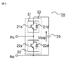
- FIG. 3 shows a transducer cell 20 employing a half-bridge configuration.
- the converter cell 20 of FIG. 3 includes a series body 23 in which a plurality (two in the illustrated case) of switches 21 and 22 are connected in series, and a DC capacitor that is connected in parallel to the series body 23 and smoothes a DC voltage. 29.
- Each of the switches 21 and 22 has a configuration in which semiconductor switching elements 21s and 22s (hereinafter simply referred to as switching elements) and diodes 21d and 22d are connected in antiparallel.
- switching elements 21 s and 22 s self-extinguishing type switching elements such as IGBTs (Insulated Gate Bipolar Transistors) and GCTs (Gate Commutated Turn-off Thyristors) are used.
- the converter cell 20 sets both terminals of the switching element 22s of the switch 22 to output terminals Po and No, and turns on and off the switching elements 21s and 22s to thereby output the output terminals Po and No. To output a positive voltage and a zero voltage of the DC capacitor 29.
- the converter cell 30 of FIG. 4 includes two series bodies 35 and 36 connected in parallel, and further includes a DC capacitor 39 that is connected in parallel to the series bodies 35 and 36 and smoothes a DC voltage.
- the series body 35 is configured by connecting in series a plurality (two in the illustrated example) of switching elements 31s and 32s to which diodes 31d and 32d are connected in antiparallel.
- the series body 36 is configured by connecting in series a switching element 34s in which either one is only the diode 33 and the other is a diode 34d connected in antiparallel.
- the switching elements 31 s, 32 s, and 34 s are composed of self-extinguishing switching elements such as IGBTs and GCTs, and switches 31, 32, and 34 configured by connecting diodes 31 d, 32 d, and 34 d in antiparallel, respectively. .
- the converter cell 30 includes an output terminal Po at the connection point between the switching elements 31 s and 32 s and the connection point between the diode 33 and the switching element 34 s as intermediate connection points between the series bodies 35 and 36. No, and switching elements 31s, 32s, and 34s are turned on and off, so that a positive voltage of the same polarity and a negative voltage of the opposite polarity are substantially equal to the magnitude of the voltage across the DC capacitor 39 from the output terminals Po and No. Is output. Moreover, the zero voltage of the state by which output terminal Po and No was short-circuited by the switching element is output.
- the converter cell 30 shown in FIG. 4 is referred to as a converter cell having a 1.5 bridge configuration.
- the converter cells 20, 30 are composed of a series body 23, 35, 36 of a plurality of switching elements or diodes and DC capacitors 29, 39 connected in parallel to the series body. , 39 is not limited to the configuration shown in FIGS. 3 and 4 as long as it selectively outputs the 39 voltages.
- converter cell 10 in phase arm 4U, 4V, 4W of power converter 1 will be further described.
- the converter cell 10 in the positive side arm 5U, 5V, 5W is shown in FIG. 4, the converter cell 20 capable of outputting the positive voltage and the zero voltage across the DC capacitor 29, as shown in FIG.
- the converter cell 30 that can output the positive voltage, the negative voltage, and the zero voltage across the DC capacitor 39 or both the converter cell 20 and the converter cell 30 is configured.
- the converter cell 10 in the negative side arm 6U, 6V, 6W is only the converter cell 30 that can output the positive voltage, the negative voltage, and the zero voltage across the DC capacitor 39 as shown in FIG. Consists of.
- all the converter cells 10 in the negative side arms 6U, 6V, 6W are constituted by the converter cells 30 capable of outputting a negative voltage, and the converter cells 10 in the positive side arms 5U, 5V, 5W are set to a positive voltage.
- a converter cell 20 capable of outputting zero voltage and a converter cell 30 capable of outputting negative voltage are combined.
- the converter cell 10 in the positive side arm 5U, 5V, 5W is configured by either the converter cell 20 or the converter cell 30.
- the converter cell 10 in the phase arms 4U, 4V, 4W is a converter cell 30 that can output a negative voltage only at least on one side arm (positive side arm 5U, 5V, 5W or negative side arm 6U, 6V, 6W). And all the converter cells 10 in the positive side arms 5U, 5V, 5W are constituted by the converter cells 30 capable of outputting a negative voltage, and the negative side arms 6U, 6V, 6W
- the converter cell 10 is configured by combining a converter cell 20 capable of outputting positive voltage and zero voltage and a converter cell 30 capable of outputting negative voltage.
- the converter cell 10 in the negative side arm 6U, 6V, 6W may be configured by either the converter cell 20 or the converter cell 30.
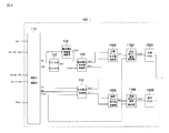
- FIG. 5 is a block diagram showing a configuration example of the control device 100 constituting the power conversion device according to Embodiment 1 of the present invention.
- the control device 100 includes a voltage command value generation unit and a PWM circuit that are configured by each control system.
- the voltage command value generation unit generates a DC voltage command value Kdc * based on the DC current Idc and DC voltage Vdc, and a normalization / calculation unit 110 that converts the detected current value / voltage value into a signal used for control.
- DC-AVR / DC-ACR control unit (DC constant voltage / DC constant current controller) 120 for controlling DC terminal voltage, and DC voltage command value Kdc * obtained by DC-AVR / DC-ACR control unit 120
- DC voltage command value calculation unit 140 for calculating DC voltage command values Vdc + * and Vdc ⁇ * of the positive side arm and the negative side arm based on the DC voltage adjustment amount ⁇ Vdc * and the DC short-circuit accident detection signal DCfault, and AC voltage AC voltage control unit 150 that controls AC voltage by calculating AC voltage command values Vac + * and Vac ⁇ * based on Vs, AC current Iac, and DC capacitor voltage Vcap; Based on the command values calculated by the DC voltage command value calculation unit 140 and the AC voltage control unit 150, the positive side and negative side arm voltage command value calculation units 160A and 160B that calculate the arm voltage command values V ++ and V ⁇ *.
- Vcell + * and Vcell- * of each converter cell based on the command values V ++ * and V ⁇ * calculated by the positive and negative arm voltage command value calculation units 160A and 160B.
- Cell individual control units 170A and 170B are provided.
- the voltage command generation unit is configured by 160A, the negative arm voltage command value calculation unit 160B, the positive cell individual control unit 170A, and the negative cell individual control unit 170B, and the voltage command value for the positive arm and the negative arm A voltage command value is generated.
- the PWM circuits 180A and 180B are configured so that, based on the positive side cell voltage command value Vcell + * and the negative side cell voltage command value Vcell- *, the positive side arm 5U, 5V, 5W, the negative side arm 6U, 6V, A gate signal for PWM control of the switching element of each converter cell 10 in 6 W is generated.
- the switching elements 21s, 22s, (31s, 32s, 34s) in each converter cell 10 are driven and controlled by the generated gate signal, and the output voltage of the power converter 1 is controlled to a desired value.
- a DC voltage command value calculation unit 140 that calculates DC voltage command values Vdc + * and Vdc ⁇ * of the positive side arm and the negative side arm at the time of a DC short-circuit accident, which is a main part of the present invention, will be described.
- the positive arm voltage command value V ++ output from the positive arm voltage command value calculation unit 160A and the negative arm voltage command value V- * output from the negative arm voltage command value calculation unit 160B will be described.
- the voltage command value V ++ for the positive arm is determined according to the DC voltage command value Vdc ++ output from the DC voltage command value calculation unit 140 and the AC voltage command value Vac ++ output from the AC voltage control unit 150, respectively.
- the negative arm voltage command value V- * is respectively applied to the DC voltage command value Vdc- * output from the DC voltage command value calculation unit 140 and the AC voltage command value Vac- * output from the AC voltage control unit 150. Will be decided accordingly. That is, the arm voltage command values V + * and V ⁇ * output from the positive and negative arm voltage command value calculation units 160A and 160B include two components, DC and AC.
- the converter cell 10 in the positive side arm 5U, 5V, 5W is composed of a converter cell 20 having a half bridge configuration capable of outputting a positive voltage and a zero voltage, and is supplied to the converter cell 10 of the positive side arm.
- the voltage command value is limited to a positive region. That is, the DC voltage command value Vdc ++ for the positive arm is limited to a positive value.
- the maximum amplitude of the AC voltage command value Vac ++ for the positive arm depends on the DC voltage command value Vdc ++.
- the converter cell 10 in the negative side arm 6U, 6V, 6W is composed of a converter cell 30 having a 1.5 bridge configuration capable of outputting positive voltage, negative voltage, and zero voltage.
- the voltage command value applied to the converter cell 10 of the negative arm can be in both positive and negative regions. That is, the DC voltage command value Vdc- * for the negative arm can be selected for both positive and negative.
- the negative arm AC voltage command value Vac- * is set to have a polarity opposite to that of the positive arm AC voltage command value Vac + *.
- the DC terminals P and N of the DC lines 2 and 3 have a configuration in which the positive side arm and the negative side arm are connected in series, the DC terminal P and N have the voltage command value V + * of the positive side arm and the negative side. A voltage substantially equal to the sum of the arm voltage command values V ⁇ * is output. Since the AC voltage command value Vac ++ for the positive arm and the AC voltage command value Vac- * for the negative arm are of opposite polarity, they cancel each other, and the DC terminals P and N have the DC voltage command value Vdc ++ for the positive arm A voltage substantially equal to the sum of the DC voltage command values Vdc- * of the negative arm is output.
- the DC voltage command value Kdc * obtained by the DC-AVR / DC-ACR control unit 120 is given to the DC voltage command value Vdc + * of the positive side arm, and the reverse of the DC voltage command value Vdc- * of the negative side arm.
- the DC voltage adjustment amount ⁇ Vdc * is output to the DC terminals P and N.
- the DC lines 2 and 3 are short-circuited, when the power converter 1 outputs the voltage of the above-mentioned DC voltage adjustment amount ⁇ Vdc * to the DC terminals P and N, the DC line is changed according to the DC line impedance. A direct current flows in 2 and 3.
- the DC voltage command value Kdc * When the DC voltage command value Kdc * is applied to the DC voltage command value Vdc + * of the positive arm and the DC voltage command value Kdc * of reverse polarity is applied to the DC voltage command value Vdc- * of the negative arm, the DC voltage command value If the magnitude of Kdc * is set to such a magnitude that the AC voltage command values Vac + * and Vac ⁇ * can be output, interconnection with the AC system is also possible.
- a current capable of detecting an accident can be caused to flow through the DC lines 2 and 3 while being connected to the AC system at the time of the accident. .
- an accident occurs, an arc voltage is generated at the DC terminals P and N. Therefore, a voltage opposite to the arc voltage is output, and after the DC terminal voltage is sufficiently low, the current that can detect the accident is applied to the DC lines 2 and 3. Shed.
- the DC voltage command value calculation unit 140 calculates the DC voltage command value Vdc + *, the DC voltage command value Kdc *, and the DC voltage of the positive arm from the DC voltage command value Kdc * obtained by the DC-AVR / DC-ACR control unit 120.
- the negative arm DC voltage command value Vdc- * is calculated from the adjustment amount ⁇ Vdc *.
- the DC voltage adjustment amount ⁇ Vdc * is equal to or higher than the voltage necessary for the current level at which the protection relay 93 operates to flow through the DC lines 2 and 3 and within the overcurrent level at which the power converter 1 stops. It is set to a preset value that is lower than the voltage.
- the DC voltage command value Vdc + * of the positive arm is configured to always give the DC voltage command value Kdc *.
- the DC voltage command value Vdc- * of the negative arm is DC short-circuited by switching the switch 142 based on a signal DCfault (normal time: 0, at time of accident: 1) given by a DC short-circuit fault detector (not shown).
- Different DC voltage command values are given depending on whether there is an accident.
- the DC voltage command value Vdc- * of the negative arm is given the DC voltage command value Kdc * when the steady state is “0”, and the DC voltage adjustment value and the DC voltage command value Kdc * are reversed when the accident is “1”.
- a value obtained by adding the amount ⁇ Vdc * to the adder 141 is given.
- the DC voltage command value Kdc * of the same component is added to the DC voltage command value Vdc + * of the positive arm and the DC voltage command value Vdc ⁇ * of the negative arm. Is given. That is, a command value that outputs a predetermined DC voltage to the DC terminals P and N is calculated.
- the DC short-circuit accident detection signal DCfault becomes “1”, the polarity of the DC voltage command value Kdc * is inverted, and the value of the DC voltage adjustment amount ⁇ Vdc * is added.
- the DC voltage adjustment amount ⁇ Vdc * is added to the DC voltage command value Kdc * and given as the DC voltage command value Vdc ⁇ * of the negative arm. If so, the DC voltage adjustment amount ⁇ Vdc * may be added to the DC voltage command value Kdc * and given as the DC voltage command value Vdc + * of the positive arm.
- all the converter cells 10 in the negative side arms 6U, 6V, 6W are constituted by the converter cells 30 capable of outputting a negative voltage, and the positive side arms 5U, 5V,
- the converter cell 10 within 5 W is composed of a converter cell 20 capable of outputting positive voltage and zero voltage.
- the DC voltage command value calculation unit 140 that calculates the DC voltage command values Vdc + * and Vdc ⁇ * of the positive side arm and the negative side arm is in a steady state at the AC end of the power converter 1 when a DC short circuit accident occurs.
- the same AC voltage is output, and a predetermined voltage at which a current level at which the protective relay 93 can detect an accident flows can be output to the DC terminal of the power converter 1.
- the protection relay 93 on the DC lines 2 and 3 can be operated to detect and remove the fault point. Become.
- the converter cell 10 is gate-blocked in the event of a DC short-circuit fault, so that the sum of the capacitor voltages of the converter cell 30 is output to the DC terminal of the power converter 1 and the fault current is suppressed.
- the ratio of the converter cells 30 in the phase arm the voltage output to the DC terminal of the power converter 1 increases, and the accident current suppression effect increases.
- the fault current suppression effect is increased, and the converter cell 10 in the positive arm is replaced by the converter cell 30 or both the converter cell 20 and the converter cell 30.
- the AC voltage of the power converter 1 is output to the AC terminal as in the normal state, It is possible to output a current at which the protective relay 93 can determine an accident to the DC terminal.
- FIG. 7 is a circuit diagram of converter cell 40 employing a full bridge configuration used as a converter cell of the power conversion device according to Embodiment 2 of the present invention.
- the converter cell 10 in the positive side arm 5U, 5V, 5W of the power converter 1 shown in FIG. 2 is used as the converter cell 20 having a half-bridge configuration, and the negative side arm 6U, 6V.
- the converter cell 10 in 6W is configured by a converter cell 40 of a full bridge cell, and the other configurations are the same as those of the first embodiment, and thus the description thereof is omitted.
- Each of the series bodies 45 and 46 is configured by connecting in series a plurality (two in the illustrated example) of switching elements 41s, 42s, 43s, and 44s to which diodes 41d, 42d, 43d, and 44d are connected in antiparallel.
- the switching elements 41 s, 42 s, 43 s, and 44 s are composed of self-extinguishing switching elements such as IGBTs and GCTs, and switches 41, 42, 43 and 44 are used.
- the converter cell 40 has terminals of the connection points of the switching elements 41 s and 42 s and the connection points of the switching elements 43 s and 44 s as intermediate connection points of the series bodies 45 and 46 at the output terminals.
- the converter cell 40 is composed of a series body of a plurality of switching elements or diodes and a DC capacitor connected in parallel to the series body, and is configured to selectively output the voltage of the DC capacitor by a switching operation.
- the configuration is not limited to that shown in FIG.
- the converter cell 10 in the positive side arm 5U, 5V, 5W is constituted by a converter cell 20 capable of outputting the positive voltage and zero voltage across the DC capacitor 29 as shown in FIG.
- the converter cell 10 in the negative side arm 6U, 6V, 6W is a converter cell 40 capable of outputting positive voltage, negative voltage and zero voltage across the DC capacitor 49 as shown in FIG. Constitute.
- the converter cell 10 in the positive arm operates so as to output a positive DC voltage and an AC voltage linked to the AC system in the event of a DC short-circuit accident, and the converter in the negative arm
- the cell 10 operates to output a negative DC voltage and an AC voltage having a polarity opposite to that of the positive arm.
- the power converter 1 when a DC short-circuit accident occurs, the power converter 1 operates to output an AC voltage similar to that in a steady state to the AC terminal, and the protection relay 93 can determine the accident at the DC terminal of the power converter 1. It is possible to output a voltage capable of flowing a large current.
- the converter cell 10 in the positive arm is configured to include the converter cell 40 or both the converter cell 20 and the converter cell 40 so that the fault current suppression effect is increased, and the converter in the negative arm is configured. Even in the main circuit configuration in which the cell 10 is composed only of the converter cell 40, the AC voltage of the power converter 1 is output to the AC terminal as in the normal state, and the protection relay 93 is provided at the DC terminal of the power converter 1. It is possible to output a voltage that can flow an accident-identifiable current.
- the converter cell 10 in the phase arm 4U, 4V, 4W is a converter cell 40 that can output a negative voltage only at least one arm (positive arm 5U, 5V, 5W or negative arm 6U, 6V, 6W).
- the converter cells 10 in the positive side arms 5U, 5V, and 5W are configured by the converter cells 40 that can output a negative voltage, and the negative side arms 6U, 6V, and 6W
- the converter cell 10 may be composed of a converter cell 20 capable of outputting positive voltage and zero voltage.
- FIG. 8 is a block diagram showing a configuration of control apparatus 100 in the power conversion apparatus according to Embodiment 3 of the present invention. 8 is the same as control device 100 in Embodiment 1 shown in FIG. 5 except that a DC voltage adjustment amount calculation unit 130 for calculating DC voltage adjustment amount ⁇ Vdc * based on DC current Idc is provided. Or, the same reference numerals are given to the corresponding parts, and the description is omitted.
- FIG. 9 shows the configuration of the DC voltage adjustment amount calculation unit 130 of the power conversion apparatus according to the third embodiment, which includes a subtracter 131 and a controller 132.
- the DC voltage adjustment amount calculation unit 130 causes a DC current command to flow a current within a current level at which the power converter 1 stops protection when the protection relay 93 on the DC lines 2 and 3 operates at a current level or higher.
- the controller 132 By controlling the controller 132 so that the difference between the value Idc * and the DC current Idc approaches zero, the DC voltage adjustment amount ⁇ Vdc * is given.
- the DC current command value Idc * is a DC component, an AC component, or an AC component if the current is equal to or higher than the current level at which the protection relay 93 on the DC lines 2 and 3 operates and within the current level at which the power converter 1 stops protection. Either one of two components of a direct current component and an alternating current component may be given. Further, a triangular wave or the like may be used instead of the AC component.
- the direct current voltage adjustment amount ⁇ Vdc * is a direct current component
- a current based on the impedance value of the resistance component of the direct current lines 2 and 3 can be passed through the direct current lines 2 and 3.
- a current based on the impedance values of the reactor components 2 and 3 can be passed through the DC lines 2 and 3, and the protection relay 93 can be operated.
- the power converter 1 outputs a voltage corresponding to the DC voltage adjustment amount ⁇ Vdc * to the DC terminal 2 and 3 at the time of a DC short-circuit accident, so that a DC current flows through the DC lines 2 and 3.
- the DC current Idc rises until an accident is detected by the protective relay 93 on the DC lines 2 and 3, and when an accident is detected, the DC circuit breaker 92 that sandwiches the accident point on the DC lines 2 and 3 opens, and the accident point is determined. Remove.
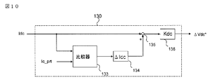
- FIG. 10 shows a configuration of DC voltage adjustment amount calculation unit 130 used in control device 100 in the power conversion device according to Embodiment 4 of the present invention.
- the configuration of the control device 100 in the power conversion device according to the fourth embodiment is the same as that in FIG. 8, and the DC voltage adjustment amount calculation unit 130 used therein has a comparator 133, a current adjustment, as shown in FIG. And a voltage command value converter 136.
- the voltage command value converter 136 calculates a DC voltage adjustment amount ⁇ Vdc * based on the magnitude of the DC current Idc, and a DC voltage that causes a current within a current level at which the power converter 1 stops protection to flow. An adjustment amount ⁇ Vdc * is given.
- the DC voltage adjustment amount calculation unit 130 shown in FIG. 10 first determines whether the magnitude of the DC current Idc is smaller than the value Ic_prt set to be equal to or lower than the protection current level of the power converter 1 by the comparator 133. If it is smaller, the comparator 133 outputs “1”, the current regulator 134 multiplies the current increase amount ⁇ Idc, and the adder 135 adds it to the DC current Idc. The voltage command value converter 136 multiplies the output of the adder 135 by the voltage command value conversion gain Kdc to calculate the DC voltage adjustment amount ⁇ Vdc *.
- the power converter 1 outputs a voltage corresponding to the DC voltage adjustment amount ⁇ Vdc * in the event of a DC short-circuit accident, thereby causing a DC component current Idc to flow through the DC lines 2 and 3.
- the DC current Idc rises until an accident is detected by the protective relay 93 on the DC lines 2 and 3, and when an accident is detected, the DC circuit breaker 92 that sandwiches the accident point on the DC lines 2 and 3 opens. Remove.
- FIG. 11 is a diagram showing a configuration of DC voltage adjustment amount calculation unit 130 used in control device 100 in the power conversion device according to Embodiment 5 of the present invention.
- the configuration of the control device 100 in the power conversion device according to the fifth embodiment is the same as that in FIG. 8, and the DC voltage adjustment amount calculation unit 130 used there is a comparator 133, a current adjustment, as shown in FIG. And a voltage command value converter 136, a maximum value holding circuit 137, a counter 138 and a multiplier 139.
- the DC voltage adjustment amount calculation unit 130 first holds the maximum value of the DC current Idc by the maximum value holding circuit 137.
- the comparator 133 determines whether the maximum value of the direct current is smaller than a value Ic_prt set to be equal to or lower than the protection current level of the power converter 1. When it is small, the comparator 133 outputs “1”, and when it is large, it outputs “0”.
- the counter 138 counts up every calculation cycle when “1” is input, and stops counting up when “0” is input.
- the output of the counter 138 is multiplied by the current amplification amount ⁇ Idc by the current regulator 134, and is multiplied by, for example, a sine wave having a frequency twice the frequency of the AC power supply 9 by the multiplier 139.
- the value to be multiplied may be a sine wave of another frequency component or a triangular wave.
- the voltage command value converter 136 multiplies the output of the multiplier 139 by the voltage command value conversion gain Kdc to calculate the DC voltage adjustment amount ⁇ Vdc *. That is, a DC voltage adjustment amount ⁇ Vdc * is applied to the DC lines 2 and 3 so that an AC component current that allows the protection relay 93 to operate is supplied.
- the power converter 1 outputs a voltage corresponding to the DC voltage adjustment amount ⁇ Vdc * in the event of a DC short-circuit accident, thereby causing a current such as an AC component to flow through the DC lines 2 and 3.
- the DC current Idc rises until an accident is detected by the protective relay 93 on the DC lines 2 and 3, and when an accident is detected, the DC circuit breaker 92 that sandwiches the accident point on the DC lines 2 and 3 opens, and the accident point is determined. Remove.
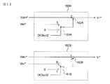
- FIG. 12 is a diagram showing a configuration of positive side and negative side arm voltage command value calculation units 160A and 160B used in control device 100 in the power conversion device according to Embodiment 6 of the present invention.
- the configuration of control device 100 in the power conversion device according to the sixth embodiment is the same as that in FIG. 5 or FIG.
- the positive arm voltage command value calculation unit 160A and the negative arm voltage command value calculation unit 160B include DC voltage command values Vdc + * and Vdc ⁇ *, an AC voltage command value Vac *, and presence / absence of AC interconnection. Based on the signal DCfault2, the positive arm voltage command value V + * and the negative arm voltage command value V- * are calculated.
- the AC output switches 161A and 161B are switched based on a signal DCfault2 (interconnection: 0, non-interconnection: 1) indicating whether or not AC interconnection is present.
- DCfault2 interconnection: 0, non-interconnection: 1
- the AC voltage command value Vac * is given to the arm DC voltage command values Vdc + * and Vdc ⁇ *
- the AC connection is “1”
- the arm DC voltage command values Vdc + * and Vdc ⁇ are supplied.
- the AC voltage command value Vac * is given as zero.
- a current is passed through the DC lines 2 and 3 using only energy stored in the DC capacitor 29 (39, 49) in the converter cell 10.
- the DC current Idc rises until an accident is detected by the protective relay 93 on the DC lines 2 and 3, and when an accident is detected, the DC circuit breaker 92 that sandwiches the accident point on the DC lines 2 and 3 opens, and the accident point is determined. Remove.
- the configuration of the converter cell 10 in the phase arm 4U, 4V, 4W of the power converter 1 includes a positive side arm 5U, 5V, 5W and a negative side arm 6U, 6V, 6W, a converter cell 20 and a converter cell.
- the configuration in which both 40 are connected in series, the configuration in any of Embodiments 1 and 2, may be used.
- FIG. 13 is a schematic configuration diagram of a three-terminal HVDC system using a power conversion device according to Embodiment 7 of the present invention.
- the power converters 1A, 1B, and 1C connected to the AC systems 9A, 9B, and 9C constitute a three-terminal HVDC system by connecting the DC terminals with DC lines 2 and 3, respectively. ing.
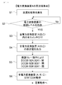
- FIG. 14 is a flowchart illustrating an accident point removal operation using the power conversion device and the protection relay according to the seventh embodiment of the present invention. With reference to FIG. 13 and FIG. 14, description will be given of DC accident removal when the DC lines 2 and 3 are short-circuited in the three-terminal HVDC system.
- each power converter 1A, 1B, 1C has a preset protection level (current value) of the power converter. Etc.) is detected (S2), and all the switching elements in the power converters 1A, 1B, 1C are turned off (S3). By turning off the switching element, it is possible to suppress the accident current flowing in each of the power conversion devices 1A, 1B, and 1C.
- each of the power conversion devices 1A, 1B, and 1C outputs a voltage that can be detected by a protective relay (not shown) at the DC end and that can be output by each of the power converters 1A, 1B, and 1C (S4).
- the impedances of the DC lines 2 and 3 increase, so that the power converters 1A, 1B, and 1C determine, for example, that the DC line accident is removed based on the fact that a predetermined current does not flow.
- the power converters 1A, 1B, and 1C cut off from the DC lines 2 and 3 can operate as STATCOM that supplies reactive power to the AC systems 9A, 9B, and 9C (S6).
- FIG. 15 is a schematic configuration diagram of a three-terminal HVDC system including a DC short-circuit fault point determination unit according to Embodiment 8 of the present invention.
- the open / close states of the circuit breaker groups 92A, 92A ′, 92B, 92B ′, 92C, 92C ′ on the DC line are given to the DC short-circuit fault point determination unit 200.
- the DC short-circuit fault point determination unit 200 determines a DC short-circuit fault point based on the switching state of the DC circuit breaker, and gives a command to operate each switch to remove the fault point.
- FIG. 16 is a flowchart illustrating an operation for removing the accident point using the power conversion device and the protection relay according to the eighth embodiment of the present invention.
- DC accident elimination and sound power transmission between two terminals when the DC lines 2 and 3 are short-circuited in the three-terminal HVDC system will be described.
- a DC short-circuit accident occurs at the closest end of the power converter 1A
- each power converter 1A, 1B, 1C detects that a preset protection level (such as a current value) of the power converter is exceeded (S12), and each power converter All switching elements in 1A, 1B and 1C are turned OFF (S13).
- a preset protection level such as a current value
- the power converter 1A outputs a voltage at which the protective relay (not shown) can detect an accident and can be output by the power converter 1A at the DC terminal (S14), so that the sensor 91A detects the accident and the circuit breaker 92A is opened (S15). Since the fault point is between the sensors 91A and 91A ′, when the converter 1A outputs a voltage to the DC terminal, a current flows through the sensor 91A, the circuit breaker 92A, and the fault point. This current is detected by the sensor 91A, and only the circuit breaker 92A is opened by operating the protective relay.
- each power converter 1A, 1B, 1C detects that a preset protection level (such as a current value) of the power converter is exceeded (S12), and each power converter All switching elements in 1A, 1B and 1C are turned OFF (S13). By turning off the switching element, it is possible to suppress the accident current flowing in each of the power conversion devices 1A, 1B, and 1C.
- a preset protection level such as a current value
- the power converter 1A outputs a voltage at which a protection relay (not shown) can detect an accident and can be output by the power converter 1A (S14), and sensors 91A, 91A ′, 91B ′ (91A) 91A ′, 91C ′) detects an accident and opens the circuit breakers 92A, 92A ′, 92B ′ (92A, 92A ′, 92C ′) (S15).
- the converter 1A Since the accident point is between the sensors 91B and 91B ′ (91C and 91C ′), the converter 1A outputs a voltage to the DC terminal, whereby the sensors 91A, 91A ′, 91B ′ (91A, 91A ′, 91C ′) are output. ), Current flows through the circuit breakers 92A, 92A ′, 92B ′ (92A, 92A ′, 92C ′) and the fault point.
- This current is detected by the sensors 91A, 91A ′, 91B ′ (91A, 91A ′, 91C ′), and the breaker 92A, 92A ′, 92B ′ (92A, 92A ′, 92C ′) is activated by the operation of the protective relay. Open. However, since the accident point is between the sensors 91B and 91B ′, power transmission between the sound terminals (power converters 1A and 1C (1B)) cannot be performed as it is.
- a signal indicating that the circuit breakers 92A, 92A ′, 92B ′ (92A, 92A ′, 92C ′) are opened is given to the DC short-circuit fault point determination unit 200 (S16), and there are a plurality of opened circuit breakers. (S17), among the opened circuit breakers, the circuit breaker 92B '(92C') farthest away from the converter and the circuit breaker 92B (93C) one distant from the converter are opened, and another circuit breaker 92A is opened. , 92A ′, 92C, 92C ′ (92A, 92A ′, 92B, 92B ′) are provided (S18 ′).
- the power converter 1A cut off from the DC lines 2 and 3 can also operate as STATCOM for supplying reactive power to the AC system 9A (S19).
- STATCOM reactive power to the AC system 9A
- the number of DC terminals may be four or more, and the number of DC line terminals and the connection method are not limited.
- the circuit breaker is opened and closed by the output of one power conversion device and the communication to the DC short-circuit fault point determination unit, but to the output of a plurality of power conversion devices and the DC short-circuit fault point determination unit The communication may not be used.
- 1, 1A, 1B, 1C power converter
- 2 positive DC line
- 3 negative DC line
- 4U, 4V, 4W phase arm
- 5U, 5V, 5W positive arm
- 6U, 6V, 6W Negative arm
- 7U, 7V, 7W AC connection point
- 8 Transformer
- 9 AC power supply
- 10, 20, 30, 40 Converter cell, 21, 22, 31, 32, 34, 41, 42 , 43, 44: switch, 21s, 22s, 31s, 32s, 34s, 41s, 42s, 43s, 44s: switching element, 21d, 22d, 31d, 32d, 34d, 41d, 42d, 43d, 44d: diode, 23, 35, 36, 45, 46: Series body, 29, 39, 49: DC capacitor
- 90 DC short-circuit accident
- 91 Sensor
- 92 DC circuit breaker
- 93 Protection relay 100: control device, 110 to 170: voltage command generation unit (110: standardization / calculation unit, 120: DC-AVR, DC-ACR
Landscapes
- Engineering & Computer Science (AREA)
- Power Engineering (AREA)
- Inverter Devices (AREA)
- Emergency Protection Circuit Devices (AREA)
- Supply And Distribution Of Alternating Current (AREA)
- Direct Current Feeding And Distribution (AREA)
- Rectifiers (AREA)
Abstract
Priority Applications (3)
| Application Number | Priority Date | Filing Date | Title |
|---|---|---|---|
| JP2017528635A JP6305653B2 (ja) | 2015-07-14 | 2016-07-07 | 電力変換装置 |
| US15/571,716 US10326355B2 (en) | 2015-07-14 | 2016-07-07 | Power conversion device |
| EP16824368.1A EP3324531B1 (fr) | 2015-07-14 | 2016-07-07 | Dispositif de conversion de puissance |
Applications Claiming Priority (2)
| Application Number | Priority Date | Filing Date | Title |
|---|---|---|---|
| JP2015-140186 | 2015-07-14 | ||
| JP2015140186 | 2015-07-14 |
Publications (1)
| Publication Number | Publication Date |
|---|---|
| WO2017010388A1 true WO2017010388A1 (fr) | 2017-01-19 |
Family
ID=57757314
Family Applications (1)
| Application Number | Title | Priority Date | Filing Date |
|---|---|---|---|
| PCT/JP2016/070076 Ceased WO2017010388A1 (fr) | 2015-07-14 | 2016-07-07 | Dispositif de conversion de puissance |
Country Status (4)
| Country | Link |
|---|---|
| US (1) | US10326355B2 (fr) |
| EP (1) | EP3324531B1 (fr) |
| JP (1) | JP6305653B2 (fr) |
| WO (1) | WO2017010388A1 (fr) |
Cited By (5)
| Publication number | Priority date | Publication date | Assignee | Title |
|---|---|---|---|---|
| WO2020110256A1 (fr) * | 2018-11-29 | 2020-06-04 | 株式会社 東芝 | Système d'alimentation électrique, dispositif de commande, et procédé d'alimentation électrique |
| CN111245222A (zh) * | 2018-11-28 | 2020-06-05 | 株式会社电装 | 用于电力转换器系统的控制设备 |
| JP2020527010A (ja) * | 2017-07-07 | 2020-08-31 | スーパーグリッド インスティテュート | 交流部に電力を管理するためのモジュールを備える変換器 |
| JP6765588B1 (ja) * | 2020-03-04 | 2020-10-07 | 三菱電機株式会社 | 電力変換システム |
| JP2021523672A (ja) * | 2018-05-18 | 2021-09-02 | シーメンス アクチエンゲゼルシヤフトSiemens Aktiengesellschaft | 高電圧直流送電の監視 |
Families Citing this family (14)
| Publication number | Priority date | Publication date | Assignee | Title |
|---|---|---|---|---|
| JP6522141B2 (ja) * | 2015-09-17 | 2019-05-29 | 三菱電機株式会社 | 電力変換装置 |
| JP6509352B2 (ja) * | 2015-09-17 | 2019-05-08 | 三菱電機株式会社 | 電力変換装置 |
| EP3352360B9 (fr) * | 2015-09-17 | 2024-07-03 | Mitsubishi Electric Corporation | Dispositif de conversion de puissance |
| US10673352B2 (en) * | 2016-03-28 | 2020-06-02 | Mitsubishi Electric Corporation | Power conversion apparatus comprising cell blocks each including cascaded converter cells and a bypass circuit connected thereto |
| DE102017202204A1 (de) * | 2017-02-13 | 2018-08-16 | Siemens Aktiengesellschaft | Umrichteranordnung |
| WO2018158935A1 (fr) * | 2017-03-03 | 2018-09-07 | 三菱電機株式会社 | Dispositif de conversion de courant et procédé de communication |
| WO2020030245A1 (fr) * | 2018-08-06 | 2020-02-13 | Abb Schweiz Ag | Procédé de commande d'un mmc |
| EP3621193B1 (fr) * | 2018-09-06 | 2025-10-29 | Hitachi Energy Ltd | Fonction de mode de défaillance de court-circuit stable artificiel à l'aide de modules parallèles pour chaque fonction de commutation |
| US11368103B2 (en) * | 2019-05-20 | 2022-06-21 | Virginia Tech Intellectual Properties, Inc. | Hybrid-current-mode switching-cycle control |
| WO2020243817A1 (fr) * | 2019-06-04 | 2020-12-10 | Transgrid Solutions Inc. | Sous-module demi-pont modifié pour convertisseur multi-niveaux de source de tension avec capacité de suppression de défaut de courant continu et procédé associé |
| CN110311543B (zh) * | 2019-07-26 | 2020-02-07 | 中国矿业大学(北京) | 级联h桥变换器故障时拓扑重构及其功率因数角计算方法 |
| EP4071996A4 (fr) * | 2019-12-03 | 2022-11-23 | Mitsubishi Electric Corporation | Dispositif de conversion de puissance |
| WO2021181583A1 (fr) * | 2020-03-11 | 2021-09-16 | 三菱電機株式会社 | Dispositif de conversion de puissance |
| CN115769477B (zh) * | 2020-07-10 | 2023-08-29 | 日立能源瑞士股份公司 | 在dc线路扰动的情况下对全桥或混合臂类型的模块化多电平转换器的控制 |
Citations (3)
| Publication number | Priority date | Publication date | Assignee | Title |
|---|---|---|---|---|
| US4544978A (en) * | 1984-03-30 | 1985-10-01 | Consolidation Coal Company | Circuit for the arcless de-energization of a direct current load |
| JP2003259649A (ja) * | 2002-03-04 | 2003-09-12 | Fuji Electric Co Ltd | 自励式直流電源装置の制御方法 |
| JP5622978B1 (ja) * | 2014-02-14 | 2014-11-12 | 三菱電機株式会社 | 直流送電系統の保護システムおよび交流直流変換器ならびに直流送電系統の遮断方法 |
Family Cites Families (14)
| Publication number | Priority date | Publication date | Assignee | Title |
|---|---|---|---|---|
| US6956752B2 (en) * | 2001-06-05 | 2005-10-18 | Koninklijke Philips Electronics N.V. | Power supply architecture with controlled power-on and power-off sequence |
| US8792261B2 (en) * | 2009-03-30 | 2014-07-29 | Hitachi, Ltd. | Power conversion device |
| JP4969614B2 (ja) * | 2009-07-21 | 2012-07-04 | 株式会社日立製作所 | 電力変換装置 |
| WO2011029480A1 (fr) * | 2009-09-11 | 2011-03-17 | Abb Research Ltd | Limitation de courant de defaut dans des systemes de transmission de puissance en courant continu |
| EP2369725B1 (fr) * | 2010-03-25 | 2012-09-26 | ABB Schweiz AG | Dispositif de court-circuit |
| WO2012103936A1 (fr) | 2011-02-01 | 2012-08-09 | Siemens Aktiengesellschaft | Procédé visant à éliminer une défaillance sur une ligne de courant continu haute tension, installation permettant de transporter un courant électrique sur une ligne de courant continu haute tension, et convertisseur correspondant |
| CN102170110B (zh) * | 2011-03-16 | 2014-01-29 | 中国电力科学研究院 | 一种模块化多电平换流器阀保护方法 |
| US20130088900A1 (en) * | 2011-10-10 | 2013-04-11 | Jong-Ho Park | Energy storage system and controlling method of the same |
| JP5894777B2 (ja) * | 2011-12-07 | 2016-03-30 | 株式会社日立製作所 | 電力変換装置 |
| WO2013115915A1 (fr) * | 2012-01-31 | 2013-08-08 | Atlantic Grid Operations A., Llc | Commande et protection d'un réseau d'alimentation c.c. |
| US9219426B2 (en) * | 2012-02-09 | 2015-12-22 | Hitachi, Ltd. | Switching element, power converter, direct current transmission system, current control device, method of controlling power converter, and method of controlling current in voltage source converter |
| JP5602176B2 (ja) * | 2012-03-27 | 2014-10-08 | 株式会社日立製作所 | 分散型電源制御装置及び分散型電源制御方法 |
| GB201209110D0 (en) * | 2012-05-24 | 2012-07-04 | Alstom Technology Ltd | Method of fault clearance |
| EP2768102B1 (fr) * | 2013-02-13 | 2016-02-10 | General Electric Technology GmbH | Dispositif d'interruption de circuit |
-
2016
- 2016-07-07 US US15/571,716 patent/US10326355B2/en active Active
- 2016-07-07 EP EP16824368.1A patent/EP3324531B1/fr active Active
- 2016-07-07 JP JP2017528635A patent/JP6305653B2/ja active Active
- 2016-07-07 WO PCT/JP2016/070076 patent/WO2017010388A1/fr not_active Ceased
Patent Citations (3)
| Publication number | Priority date | Publication date | Assignee | Title |
|---|---|---|---|---|
| US4544978A (en) * | 1984-03-30 | 1985-10-01 | Consolidation Coal Company | Circuit for the arcless de-energization of a direct current load |
| JP2003259649A (ja) * | 2002-03-04 | 2003-09-12 | Fuji Electric Co Ltd | 自励式直流電源装置の制御方法 |
| JP5622978B1 (ja) * | 2014-02-14 | 2014-11-12 | 三菱電機株式会社 | 直流送電系統の保護システムおよび交流直流変換器ならびに直流送電系統の遮断方法 |
Non-Patent Citations (1)
| Title |
|---|
| See also references of EP3324531A4 * |
Cited By (10)
| Publication number | Priority date | Publication date | Assignee | Title |
|---|---|---|---|---|
| JP2020527010A (ja) * | 2017-07-07 | 2020-08-31 | スーパーグリッド インスティテュート | 交流部に電力を管理するためのモジュールを備える変換器 |
| JP7168645B2 (ja) | 2017-07-07 | 2022-11-09 | スーパーグリッド インスティテュート | 交流部に電力を管理するためのモジュールを備える変換器 |
| JP2021523672A (ja) * | 2018-05-18 | 2021-09-02 | シーメンス アクチエンゲゼルシヤフトSiemens Aktiengesellschaft | 高電圧直流送電の監視 |
| JP7036520B2 (ja) | 2018-05-18 | 2022-03-15 | シーメンス アクチエンゲゼルシヤフト | 高電圧直流送電の監視 |
| CN111245222A (zh) * | 2018-11-28 | 2020-06-05 | 株式会社电装 | 用于电力转换器系统的控制设备 |
| CN111245222B (zh) * | 2018-11-28 | 2024-01-02 | 株式会社电装 | 用于电力转换器系统的控制设备 |
| WO2020110256A1 (fr) * | 2018-11-29 | 2020-06-04 | 株式会社 東芝 | Système d'alimentation électrique, dispositif de commande, et procédé d'alimentation électrique |
| JP6765588B1 (ja) * | 2020-03-04 | 2020-10-07 | 三菱電機株式会社 | 電力変換システム |
| WO2021176615A1 (fr) | 2020-03-04 | 2021-09-10 | 三菱電機株式会社 | Système convertisseur de puissance |
| US12294291B2 (en) | 2020-03-04 | 2025-05-06 | Mitsubishi Electric Corporation | Power conversion system |
Also Published As
| Publication number | Publication date |
|---|---|
| EP3324531A4 (fr) | 2019-04-03 |
| US20180159422A1 (en) | 2018-06-07 |
| JP6305653B2 (ja) | 2018-04-04 |
| EP3324531A1 (fr) | 2018-05-23 |
| EP3324531B1 (fr) | 2022-11-23 |
| JPWO2017010388A1 (ja) | 2017-11-24 |
| US10326355B2 (en) | 2019-06-18 |
Similar Documents
| Publication | Publication Date | Title |
|---|---|---|
| JP6305653B2 (ja) | 電力変換装置 | |
| JP6207730B2 (ja) | 直流送電電力変換装置および直流送電電力変換方法 | |
| JP6227192B2 (ja) | 電力変換装置 | |
| JP6526344B2 (ja) | 電力変換装置および電力システム | |
| US8508957B2 (en) | Power conversion device for converting DC power to AC power | |
| Ounejjar et al. | A novel six-band hysteresis control for the packed U cells seven-level converter: Experimental validation | |
| JP5248611B2 (ja) | 電力変換装置 | |
| WO2020136699A1 (fr) | Dispositif de conversion de puissance | |
| MX2011001963A (es) | Aparato de conversion de energia. | |
| Ashraf et al. | A new hybrid dual active bridge modular multilevel based DC–DC converter for HVDC networks | |
| Xu et al. | Open-loop voltage balancing algorithm for two-port full-bridge MMC-HVDC system | |
| JP5645209B2 (ja) | 電力変換装置 | |
| WO2020136698A1 (fr) | Dispositif de conversion de puissance | |
| CN108352780A (zh) | 用于处理ac侧故障的模块化多电平转换器 | |
| Yu et al. | DC fault current control of modular multilevel converter with SiC-based Power Electronics Building Blocks | |
| JP2023067539A (ja) | 電力変換装置 | |
| KR101542940B1 (ko) | 멀티 레벨 컨버터의 사고 전류 저감 구조 및 이를 이용한 장치 | |
| JP7734681B2 (ja) | 無効電力補償装置 | |
| Chaffey et al. | DC fault ride through of multilevel converters | |
| Maharjan et al. | Control of a 6.6-kV transformerless STATCOM based on the MMCC-SDBC using SiC MOSFETs | |
| WO2020030245A1 (fr) | Procédé de commande d'un mmc | |
| EP4726996A1 (fr) | Dispositif de conversion de puissance | |
| WO2023032426A1 (fr) | Dispositif de conversion de puissance | |
| WO2022208759A1 (fr) | Dispositif de conversion d'énergie |
Legal Events
| Date | Code | Title | Description |
|---|---|---|---|
| 121 | Ep: the epo has been informed by wipo that ep was designated in this application |
Ref document number: 16824368 Country of ref document: EP Kind code of ref document: A1 |
|
| ENP | Entry into the national phase |
Ref document number: 2017528635 Country of ref document: JP Kind code of ref document: A |
|
| WWE | Wipo information: entry into national phase |
Ref document number: 15571716 Country of ref document: US |
|
| NENP | Non-entry into the national phase |
Ref country code: DE |
|
| WWE | Wipo information: entry into national phase |
Ref document number: 2016824368 Country of ref document: EP |