WO2017010481A1 - Procédé et dispositif pour la fabrication d'une unité de palier - Google Patents
Procédé et dispositif pour la fabrication d'une unité de palier Download PDFInfo
- Publication number
- WO2017010481A1 WO2017010481A1 PCT/JP2016/070551 JP2016070551W WO2017010481A1 WO 2017010481 A1 WO2017010481 A1 WO 2017010481A1 JP 2016070551 W JP2016070551 W JP 2016070551W WO 2017010481 A1 WO2017010481 A1 WO 2017010481A1
- Authority
- WO
- WIPO (PCT)
- Prior art keywords
- hub
- end surface
- axial direction
- axial
- central axis
- Prior art date
- Legal status (The legal status is an assumption and is not a legal conclusion. Google has not performed a legal analysis and makes no representation as to the accuracy of the status listed.)
- Ceased
Links
Images















Classifications
-
- F—MECHANICAL ENGINEERING; LIGHTING; HEATING; WEAPONS; BLASTING
- F16—ENGINEERING ELEMENTS AND UNITS; GENERAL MEASURES FOR PRODUCING AND MAINTAINING EFFECTIVE FUNCTIONING OF MACHINES OR INSTALLATIONS; THERMAL INSULATION IN GENERAL
- F16C—SHAFTS; FLEXIBLE SHAFTS; ELEMENTS OR CRANKSHAFT MECHANISMS; ROTARY BODIES OTHER THAN GEARING ELEMENTS; BEARINGS
- F16C43/00—Assembling bearings
- F16C43/04—Assembling rolling-contact bearings
- F16C43/06—Placing rolling bodies in cages or bearings
- F16C43/08—Placing rolling bodies in cages or bearings by deforming the cages or the races
-
- B—PERFORMING OPERATIONS; TRANSPORTING
- B21—MECHANICAL METAL-WORKING WITHOUT ESSENTIALLY REMOVING MATERIAL; PUNCHING METAL
- B21D—WORKING OR PROCESSING OF SHEET METAL OR METAL TUBES, RODS OR PROFILES WITHOUT ESSENTIALLY REMOVING MATERIAL; PUNCHING METAL
- B21D39/00—Application of procedures in order to connect objects or parts, e.g. coating with sheet metal otherwise than by plating; Tube expanders
-
- B—PERFORMING OPERATIONS; TRANSPORTING
- B21—MECHANICAL METAL-WORKING WITHOUT ESSENTIALLY REMOVING MATERIAL; PUNCHING METAL
- B21D—WORKING OR PROCESSING OF SHEET METAL OR METAL TUBES, RODS OR PROFILES WITHOUT ESSENTIALLY REMOVING MATERIAL; PUNCHING METAL
- B21D39/00—Application of procedures in order to connect objects or parts, e.g. coating with sheet metal otherwise than by plating; Tube expanders
- B21D39/02—Application of procedures in order to connect objects or parts, e.g. coating with sheet metal otherwise than by plating; Tube expanders of sheet metal by folding, e.g. connecting edges of a sheet to form a cylinder
- B21D39/021—Application of procedures in order to connect objects or parts, e.g. coating with sheet metal otherwise than by plating; Tube expanders of sheet metal by folding, e.g. connecting edges of a sheet to form a cylinder for panels, e.g. vehicle doors
- B21D39/023—Application of procedures in order to connect objects or parts, e.g. coating with sheet metal otherwise than by plating; Tube expanders of sheet metal by folding, e.g. connecting edges of a sheet to form a cylinder for panels, e.g. vehicle doors using rollers
-
- B—PERFORMING OPERATIONS; TRANSPORTING
- B21—MECHANICAL METAL-WORKING WITHOUT ESSENTIALLY REMOVING MATERIAL; PUNCHING METAL
- B21J—FORGING; HAMMERING; PRESSING METAL; RIVETING; FORGE FURNACES
- B21J5/00—Methods for forging, hammering, or pressing; Special equipment or accessories therefor
- B21J5/06—Methods for forging, hammering, or pressing; Special equipment or accessories therefor for performing particular operations
- B21J5/12—Forming profiles on internal or external surfaces
-
- B—PERFORMING OPERATIONS; TRANSPORTING
- B21—MECHANICAL METAL-WORKING WITHOUT ESSENTIALLY REMOVING MATERIAL; PUNCHING METAL
- B21J—FORGING; HAMMERING; PRESSING METAL; RIVETING; FORGE FURNACES
- B21J9/00—Forging presses
- B21J9/02—Special design or construction
-
- B—PERFORMING OPERATIONS; TRANSPORTING
- B21—MECHANICAL METAL-WORKING WITHOUT ESSENTIALLY REMOVING MATERIAL; PUNCHING METAL
- B21J—FORGING; HAMMERING; PRESSING METAL; RIVETING; FORGE FURNACES
- B21J9/00—Forging presses
- B21J9/02—Special design or construction
- B21J9/025—Special design or construction with rolling or wobbling dies
-
- B—PERFORMING OPERATIONS; TRANSPORTING
- B21—MECHANICAL METAL-WORKING WITHOUT ESSENTIALLY REMOVING MATERIAL; PUNCHING METAL
- B21J—FORGING; HAMMERING; PRESSING METAL; RIVETING; FORGE FURNACES
- B21J9/00—Forging presses
- B21J9/02—Special design or construction
- B21J9/027—Special design or construction with punches moving along auxiliary lateral directions
-
- B—PERFORMING OPERATIONS; TRANSPORTING
- B21—MECHANICAL METAL-WORKING WITHOUT ESSENTIALLY REMOVING MATERIAL; PUNCHING METAL
- B21K—MAKING FORGED OR PRESSED METAL PRODUCTS, e.g. HORSE-SHOES, RIVETS, BOLTS OR WHEELS
- B21K1/00—Making machine elements
- B21K1/04—Making machine elements ball-races or sliding bearing races
-
- B—PERFORMING OPERATIONS; TRANSPORTING
- B21—MECHANICAL METAL-WORKING WITHOUT ESSENTIALLY REMOVING MATERIAL; PUNCHING METAL
- B21K—MAKING FORGED OR PRESSED METAL PRODUCTS, e.g. HORSE-SHOES, RIVETS, BOLTS OR WHEELS
- B21K1/00—Making machine elements
- B21K1/28—Making machine elements wheels; discs
- B21K1/30—Making machine elements wheels; discs with gear-teeth
-
- B—PERFORMING OPERATIONS; TRANSPORTING
- B21—MECHANICAL METAL-WORKING WITHOUT ESSENTIALLY REMOVING MATERIAL; PUNCHING METAL
- B21K—MAKING FORGED OR PRESSED METAL PRODUCTS, e.g. HORSE-SHOES, RIVETS, BOLTS OR WHEELS
- B21K1/00—Making machine elements
- B21K1/28—Making machine elements wheels; discs
- B21K1/40—Making machine elements wheels; discs hubs
-
- B—PERFORMING OPERATIONS; TRANSPORTING
- B21—MECHANICAL METAL-WORKING WITHOUT ESSENTIALLY REMOVING MATERIAL; PUNCHING METAL
- B21K—MAKING FORGED OR PRESSED METAL PRODUCTS, e.g. HORSE-SHOES, RIVETS, BOLTS OR WHEELS
- B21K1/00—Making machine elements
- B21K1/76—Making machine elements elements not mentioned in one of the preceding groups
- B21K1/762—Coupling members for conveying mechanical motion, e.g. universal joints
- B21K1/765—Outer elements of coupling members
-
- B—PERFORMING OPERATIONS; TRANSPORTING
- B21—MECHANICAL METAL-WORKING WITHOUT ESSENTIALLY REMOVING MATERIAL; PUNCHING METAL
- B21K—MAKING FORGED OR PRESSED METAL PRODUCTS, e.g. HORSE-SHOES, RIVETS, BOLTS OR WHEELS
- B21K25/00—Uniting components to form integral members, e.g. turbine wheels and shafts, caulks with inserts, with or without shaping of the components
-
- B—PERFORMING OPERATIONS; TRANSPORTING
- B60—VEHICLES IN GENERAL
- B60B—VEHICLE WHEELS; CASTORS; AXLES FOR WHEELS OR CASTORS; INCREASING WHEEL ADHESION
- B60B35/00—Axle units; Parts thereof ; Arrangements for lubrication of axles
- B60B35/02—Dead axles, i.e. not transmitting torque
-
- F—MECHANICAL ENGINEERING; LIGHTING; HEATING; WEAPONS; BLASTING
- F16—ENGINEERING ELEMENTS AND UNITS; GENERAL MEASURES FOR PRODUCING AND MAINTAINING EFFECTIVE FUNCTIONING OF MACHINES OR INSTALLATIONS; THERMAL INSULATION IN GENERAL
- F16C—SHAFTS; FLEXIBLE SHAFTS; ELEMENTS OR CRANKSHAFT MECHANISMS; ROTARY BODIES OTHER THAN GEARING ELEMENTS; BEARINGS
- F16C19/00—Bearings with rolling contact, for exclusively rotary movement
- F16C19/02—Bearings with rolling contact, for exclusively rotary movement with bearing balls essentially of the same size in one or more circular rows
- F16C19/14—Bearings with rolling contact, for exclusively rotary movement with bearing balls essentially of the same size in one or more circular rows for both radial and axial load
- F16C19/18—Bearings with rolling contact, for exclusively rotary movement with bearing balls essentially of the same size in one or more circular rows for both radial and axial load with two or more rows of balls
-
- F—MECHANICAL ENGINEERING; LIGHTING; HEATING; WEAPONS; BLASTING
- F16—ENGINEERING ELEMENTS AND UNITS; GENERAL MEASURES FOR PRODUCING AND MAINTAINING EFFECTIVE FUNCTIONING OF MACHINES OR INSTALLATIONS; THERMAL INSULATION IN GENERAL
- F16C—SHAFTS; FLEXIBLE SHAFTS; ELEMENTS OR CRANKSHAFT MECHANISMS; ROTARY BODIES OTHER THAN GEARING ELEMENTS; BEARINGS
- F16C35/00—Rigid support of bearing units; Housings, e.g. caps, covers
- F16C35/04—Rigid support of bearing units; Housings, e.g. caps, covers in the case of ball or roller bearings
- F16C35/06—Mounting or dismounting of ball or roller bearings; Fixing them onto shaft or in housing
- F16C35/063—Fixing them on the shaft
-
- F—MECHANICAL ENGINEERING; LIGHTING; HEATING; WEAPONS; BLASTING
- F16—ENGINEERING ELEMENTS AND UNITS; GENERAL MEASURES FOR PRODUCING AND MAINTAINING EFFECTIVE FUNCTIONING OF MACHINES OR INSTALLATIONS; THERMAL INSULATION IN GENERAL
- F16C—SHAFTS; FLEXIBLE SHAFTS; ELEMENTS OR CRANKSHAFT MECHANISMS; ROTARY BODIES OTHER THAN GEARING ELEMENTS; BEARINGS
- F16C43/00—Assembling bearings
- F16C43/04—Assembling rolling-contact bearings
-
- F—MECHANICAL ENGINEERING; LIGHTING; HEATING; WEAPONS; BLASTING
- F16—ENGINEERING ELEMENTS AND UNITS; GENERAL MEASURES FOR PRODUCING AND MAINTAINING EFFECTIVE FUNCTIONING OF MACHINES OR INSTALLATIONS; THERMAL INSULATION IN GENERAL
- F16D—COUPLINGS FOR TRANSMITTING ROTATION; CLUTCHES; BRAKES
- F16D1/00—Couplings for rigidly connecting two coaxial shafts or other movable machine elements
- F16D1/06—Couplings for rigidly connecting two coaxial shafts or other movable machine elements for attachment of a member on a shaft or on a shaft-end
- F16D1/076—Couplings for rigidly connecting two coaxial shafts or other movable machine elements for attachment of a member on a shaft or on a shaft-end by clamping together two faces perpendicular to the axis of rotation, e.g. with bolted flanges
-
- B—PERFORMING OPERATIONS; TRANSPORTING
- B60—VEHICLES IN GENERAL
- B60B—VEHICLE WHEELS; CASTORS; AXLES FOR WHEELS OR CASTORS; INCREASING WHEEL ADHESION
- B60B35/00—Axle units; Parts thereof ; Arrangements for lubrication of axles
- B60B35/02—Dead axles, i.e. not transmitting torque
- B60B35/10—Dead axles, i.e. not transmitting torque adjustable for varying track
- B60B35/1072—Dead axles, i.e. not transmitting torque adjustable for varying track by transversally movable elements
- B60B35/1081—Dead axles, i.e. not transmitting torque adjustable for varying track by transversally movable elements the element is a wheel
-
- F—MECHANICAL ENGINEERING; LIGHTING; HEATING; WEAPONS; BLASTING
- F16—ENGINEERING ELEMENTS AND UNITS; GENERAL MEASURES FOR PRODUCING AND MAINTAINING EFFECTIVE FUNCTIONING OF MACHINES OR INSTALLATIONS; THERMAL INSULATION IN GENERAL
- F16C—SHAFTS; FLEXIBLE SHAFTS; ELEMENTS OR CRANKSHAFT MECHANISMS; ROTARY BODIES OTHER THAN GEARING ELEMENTS; BEARINGS
- F16C19/00—Bearings with rolling contact, for exclusively rotary movement
- F16C19/02—Bearings with rolling contact, for exclusively rotary movement with bearing balls essentially of the same size in one or more circular rows
- F16C19/14—Bearings with rolling contact, for exclusively rotary movement with bearing balls essentially of the same size in one or more circular rows for both radial and axial load
- F16C19/18—Bearings with rolling contact, for exclusively rotary movement with bearing balls essentially of the same size in one or more circular rows for both radial and axial load with two or more rows of balls
- F16C19/181—Bearings with rolling contact, for exclusively rotary movement with bearing balls essentially of the same size in one or more circular rows for both radial and axial load with two or more rows of balls with angular contact
- F16C19/183—Bearings with rolling contact, for exclusively rotary movement with bearing balls essentially of the same size in one or more circular rows for both radial and axial load with two or more rows of balls with angular contact with two rows at opposite angles
- F16C19/184—Bearings with rolling contact, for exclusively rotary movement with bearing balls essentially of the same size in one or more circular rows for both radial and axial load with two or more rows of balls with angular contact with two rows at opposite angles in O-arrangement
- F16C19/186—Bearings with rolling contact, for exclusively rotary movement with bearing balls essentially of the same size in one or more circular rows for both radial and axial load with two or more rows of balls with angular contact with two rows at opposite angles in O-arrangement with three raceways provided integrally on parts other than race rings, e.g. third generation hubs
-
- F—MECHANICAL ENGINEERING; LIGHTING; HEATING; WEAPONS; BLASTING
- F16—ENGINEERING ELEMENTS AND UNITS; GENERAL MEASURES FOR PRODUCING AND MAINTAINING EFFECTIVE FUNCTIONING OF MACHINES OR INSTALLATIONS; THERMAL INSULATION IN GENERAL
- F16C—SHAFTS; FLEXIBLE SHAFTS; ELEMENTS OR CRANKSHAFT MECHANISMS; ROTARY BODIES OTHER THAN GEARING ELEMENTS; BEARINGS
- F16C2226/00—Joining parts; Fastening; Assembling or mounting parts
- F16C2226/50—Positive connections
- F16C2226/52—Positive connections with plastic deformation, e.g. caulking or staking
-
- F—MECHANICAL ENGINEERING; LIGHTING; HEATING; WEAPONS; BLASTING
- F16—ENGINEERING ELEMENTS AND UNITS; GENERAL MEASURES FOR PRODUCING AND MAINTAINING EFFECTIVE FUNCTIONING OF MACHINES OR INSTALLATIONS; THERMAL INSULATION IN GENERAL
- F16C—SHAFTS; FLEXIBLE SHAFTS; ELEMENTS OR CRANKSHAFT MECHANISMS; ROTARY BODIES OTHER THAN GEARING ELEMENTS; BEARINGS
- F16C2326/00—Articles relating to transporting
- F16C2326/01—Parts of vehicles in general
- F16C2326/02—Wheel hubs or castors
-
- F—MECHANICAL ENGINEERING; LIGHTING; HEATING; WEAPONS; BLASTING
- F16—ENGINEERING ELEMENTS AND UNITS; GENERAL MEASURES FOR PRODUCING AND MAINTAINING EFFECTIVE FUNCTIONING OF MACHINES OR INSTALLATIONS; THERMAL INSULATION IN GENERAL
- F16C—SHAFTS; FLEXIBLE SHAFTS; ELEMENTS OR CRANKSHAFT MECHANISMS; ROTARY BODIES OTHER THAN GEARING ELEMENTS; BEARINGS
- F16C43/00—Assembling bearings
- F16C43/04—Assembling rolling-contact bearings
- F16C43/06—Placing rolling bodies in cages or bearings
- F16C43/08—Placing rolling bodies in cages or bearings by deforming the cages or the races
- F16C43/086—Placing rolling bodies in cages or bearings by deforming the cages or the races by plastic deformation of the race
Definitions
- the present invention relates to a method and apparatus for manufacturing a bearing unit.
- This application claims priority based on Japanese Patent Application No. 2015-139543 filed in Japan on July 13, 2015 and Japanese Patent Application No. 2015-196510 filed in Japan on October 2, 2015. , The contents of which are incorporated herein.
- Patent Document 1 discloses a bearing unit in which a face spline for power transmission is provided on an end face of an inner ring.
- a swing press machine rotary ⁇ ⁇ ⁇ forging (machine) has been used for processing the face spline.
- An object of an aspect of the present invention is to provide a method for manufacturing a bearing unit that can reduce the manufacturing cost while ensuring the durability of the bearing unit.
- the eccentric load applied to the other axial end of the hub main body is reduced. It is an object of the present invention to provide a bearing unit manufacturing method and manufacturing apparatus that can be reduced or substantially reduced to zero.
- the bearing unit manufacturing method includes a step of setting a workpiece on a press device and a step of plastically processing the workpiece.
- the plastic working step includes moving a part of the plurality of elements arranged in the circumferential direction in the axial direction to press the first region of the workpiece, and another part of the plurality of elements in the axial direction. Moving and pressing the second region of the workpiece.
- a bearing unit manufacturing apparatus in another aspect of the present invention, includes a holder on which a workpiece is set, a plurality of elements arranged in the circumferential direction, each movable in the axial direction, and a part of the plurality of elements. A mode in which the first region of the workpiece is pressed by moving in the axial direction, and a mode in which another part of the plurality of elements is moved in the axial direction and the second region of the workpiece is pressed. The mechanism which has these.
- the bearing unit includes a hub body and an inner ring.
- the hub main body has an inner ring raceway on one axial side on the outer peripheral surface of the axially intermediate portion.
- the inner ring has an inner ring raceway on the other side in the axial direction on the outer peripheral surface, and is fitted on a portion near the other end in the axial direction of the hub body. Then, the other end surface in the axial direction of the inner ring is held down by a caulking portion formed by plastically deforming a cylindrical portion provided at the other end portion in the axial direction of the hub body in the radially outward direction, and the inner ring is moved to the hub body. It is fixed to support.
- the bearing unit includes an outer ring having a double row outer ring raceway on an inner peripheral surface, and a plurality of rolling elements provided between the outer ring raceway and the inner ring raceways so as to be capable of rolling.
- the bearing unit includes an outer ring having a double row outer ring raceway on an inner peripheral surface, and a plurality of rolling elements provided between the outer ring raceway and the inner ring raceways so as to be capable of rolling.
- the manufacturing method of the bearing unit is formed by combining a plurality of punch elements that are divided into a plurality in the circumferential direction, each capable of axial displacement and prevented from circumferential displacement.
- the one end surface in the axial direction of the molding punch having the same number of teeth as the number of teeth on the hub-side face spline is opposed to the other end surface in the axial direction of the caulking portion.
- the roll is Rotate around the center axis of the hub body.
- an inclination angle of the central axis of the roll with respect to the central axis of the hub body is set to 15 degrees or more.
- the inclination angle can be 30 degrees or less.
- the above numerical value is an example, and the present invention is not limited to this.
- the forming punch is formed from the punch elements divided into the same number as the number of teeth of the processed teeth. Specifically, each of these punch elements is divided for each processing tooth ⁇ divided at the center position of the tooth bottom existing between adjacent processing teeth (the center position in the circumferential direction of the forming punch) ⁇ . Or it shall be divided
- the rear side edge in the rotational direction of the roll centered on the central axis of the hub body, Both sides in the circumferential direction of the other end face in the axial direction of the punch element existing on the front side in the rotation direction of the roll centered on the central axis of the hub body of the one punch element in a state pressed by the pressing surface of the roll Among the edges, the rear edge in the rotation direction of the roll centering on the central axis of the hub body (that is, the one edge on the one punch element side) is not pressed by the pressing surface of the roll.
- the rear surface in the rotational direction of the roll centered on the central axis of the hub body, the central axis of the hub body, and the central axis of the roll
- the other end surface in the axial direction of the punch element existing on the front side in the rotation direction of the roll around the central axis of the hub body of the one punch element in a state where a virtual plane including the same exists on the same plane
- the side edge on the one punch element side and the pressing surface of the roll are in contact or close to each other and are opposed to each other in the circumferential direction of both sides of the circumferential direction (that is, they exist on the front side in the rotation direction of the roll).
- the pressing amount by the pressing surface of the roll (the pressing amount in the axial direction of the hub main body) is adjusted so that the other end surface in the axial direction of the punch element is not strongly pressed.
- a part of each punch element is moved to each punch. By abutting against the stepped surface provided in the part holding the element, the punch elements are prevented from being further displaced in the other axial direction.
- the bearing unit has a second axial end of the hub main body to apply a coupling force directed to one side in the axial direction with respect to the hub main body to an inner ring fitted on the hub main body.
- the other end surface in the axial direction of the inner ring is held down by a caulking portion formed by plastic deformation of a cylindrical portion provided in the portion radially outward.
- the bearing unit has a hub main body having an inner ring raceway on one side in the axial direction on the outer peripheral surface of the axially intermediate portion, and an inner ring raceway on the other side in the axial direction on the outer peripheral surface. And an inner ring fitted on the outside.
- the hub main body is restrained by the other end surface in the axial direction of the inner ring by a caulking portion formed by plastically deforming a cylindrical portion provided at the other axial end portion of the hub main body radially outward.
- the inner ring is fixed to.
- an outer ring having a double row outer ring raceway on the inner peripheral surface, and a plurality of rolling elements provided between the outer ring raceway and the inner ring raceways are provided so as to be capable of rolling.
- a manufacturing method of a bearing unit includes a plurality of mold elements that are arranged side by side in a circumferential direction around the central axis of the hub body and that are capable of axial displacement independent of each other.
- One end face in the axial direction of the caulking part molding die (the one axial end face of each molding die element) formed in combination is brought into contact with the other axial end face of the cylindrical part.
- a plurality of rollers arranged at a plurality of locations smaller than the total number of the respective molding die elements are arranged in the axial direction of the caulking portion molding die.
- the other end surface (that is, the other end surface in the axial direction of a part of the molding element facing each roller among the molding elements) is slidably pressed.
- the rollers roll in a circumferential direction around the central axis of the hub body (that is, the rollers are sequentially pressed against the other axial end surfaces of the mold elements).
- the one end surface in the axial direction of each mold element is sequentially pressed against the other end surface in the axial direction of the cylindrical portion, thereby processing the cylindrical portion into the caulking portion.
- a hub-side face spline that is an uneven portion in the circumferential direction is formed on the other end surface in the axial direction of the caulking portion.
- it is arranged side by side in the circumferential direction centering on the central axis of the hub body, and is formed by combining a plurality of mold elements provided to be capable of axial displacement independent of each other.
- One end face in the axial direction of the face spline mold that is, the face having the same number of teeth as the hub face spline, or one end face in the axial direction of each mold element It abuts on the other end surface.
- a plurality of rollers arranged at a plurality of locations smaller than the total number of the respective mold elements are arranged in the axial direction of the face spline mold.
- the other end surface that is, the other end surface in the axial direction of a part of the molding element facing each roller among the molding elements
- the rollers roll in a circumferential direction around the central axis of the hub body (that is, the rollers are sequentially pressed against the other axial end surfaces of the mold elements).
- the hub-side face spline is formed on the other end surface in the axial direction of the caulking portion by sequentially pressing one end surface in the axial direction of each mold element on the other end surface in the axial direction of the caulking portion.
- the hub-side face spline may be formed after the caulking portion is formed.
- the rollers are arranged on a circumference centered on the central axis of the hub body in a positional relationship that is rotationally symmetric about the central axis of the hub body (for example, at equal intervals in the circumferential direction).
- the rotational symmetry is a property in which when m is an integer of 2 or more and a certain positional relationship is rotated (360 / m) ° about a certain axis, the same positional relationship as before rotation is obtained. (Such a positional relationship is referred to as an m-fold symmetrical positional relationship).
- the positional relationship of m places at equal intervals in the circumferential direction on the circumference centered on a certain axis is a positional relationship of m-fold symmetry.
- a bearing unit manufacturing apparatus includes a caulking portion molding die, a pressing unit, and a pressing unit drive mechanism.
- the caulking part molding die is arranged side by side in the circumferential direction centering on the central axis of the hub body, and includes a plurality of molding element elements provided so as to be capable of axial displacement independent of each other. It is formed in combination, and one axial end surface (the one axial end surface of each mold element) can be brought into contact with the other axial end surface of the cylindrical portion of the hub body.
- the pressing unit includes a plurality of rollers arranged at a plurality of locations smaller than the total number of the molding element elements in the circumferential direction around the central axis of the hub body, and It can contact
- the pressing unit driving mechanism abuts one end surface in the axial direction of the caulking portion molding die on the other axial end surface of the cylindrical portion and the other end surface in the axial direction of the caulking portion molding die.
- a driving force for rolling the rollers in a circumferential direction around the central axis of the hub body can be applied to the pressing unit in a state where the rollers are pressed to be able to roll.
- a bearing unit manufacturing apparatus includes a face spline mold, a pressing unit, and a pressing unit drive mechanism.
- the face spline mold is arranged side by side in the circumferential direction centering on the central axis of the hub body, and a plurality of mold elements provided to be capable of axial displacement independent of each other.
- An axial end surface that is, a surface having the same number of teeth as the number of teeth of the hub-side face spline, or an axial end surface of each mold element) is formed in combination, and the axial direction of the caulking portion It can contact the other end surface.
- the pressing unit includes a plurality of rollers arranged at a plurality of locations smaller than the total number of the molding element elements in the circumferential direction around the central axis of the hub body, and It is possible to contact the other end surface in the axial direction of the face spline mold so as to allow rolling.
- the pressing unit driving mechanism abuts one end surface in the axial direction of the face spline mold on the other end surface in the axial direction of the caulking portion, and the other end surface in the axial direction of the face spline mold.
- a driving force for rolling the rollers in a circumferential direction around the central axis of the hub body can be applied to the pressing unit in a state where the rollers are pressed to be able to roll.
- the face spline mold can be formed from the mold elements divided into the same number as the number of teeth of the processed teeth. Specifically, each mold element is divided for each machining tooth ⁇ the center position of the tooth bottom existing between adjacent machining teeth (for example, the center in the circumferential direction of the face spline mold) Divided by position), or divided at the center position of the tip of each processed tooth.
- the rollers are arranged on a circumference centered on the central axis of the hub body in a positional relationship that is rotationally symmetric about the central axis of the hub body (for example, at equal intervals in the circumferential direction). To do.
- the eccentric load applied to the other axial end of the hub body is reduced. It can be reduced or substantially zero.
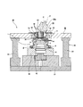
- Sectional drawing which shows one example of the rocking press apparatus which can implement the manufacturing method of 1st Embodiment of this invention in the state before starting the process for forming a hub side face spline.
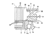
- Sectional drawing which shows one example of the said rocking press apparatus of 1st Embodiment in the state in process.
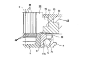
- Sectional drawing which shows one example of the said rocking press apparatus of 1st Embodiment in the state of completion of a process.
- the enlarged view which expanded the a part in FIG.
- the enlarged view which expanded the b section in FIG. The perspective view which takes out and shows one punch element.
- the top view which looked at the punch element of FIG. 5A from upper direction.
- FIG. 5B is a cross-sectional view corresponding to the line cc in FIG. 5B.
- Sectional drawing which shows a part of processing apparatus regarding 2nd Embodiment of this invention in the state before starting the process which forms a crimping part.
- a part of the processing device is placed under the caulking portion molding die on the other axial end surface of the cylindrical portion of the hub body following the state shown in FIG. Sectional drawing shown in the state which contacted the end surface.
- a part of the processing device is brought into contact with the upper end surface of the caulking portion molding die following the state shown in FIG. Sectional drawing shown in a state.
- FIG. 17 which shows an example of the said rocking press apparatus of 2nd Embodiment.
- FIG. 20 is a cross-sectional view corresponding to the line cc in FIG. 20B in an example of the rocking press device of the second embodiment.
- Sectional drawing which shows a part of processing apparatus regarding 3rd Embodiment of this invention in the state before starting the process which forms a hub side face spline.
- Sectional drawing which shows a part of processing apparatus of 3rd Embodiment in the state which made the some roller contact
- Sectional drawing which shows a part of the processing apparatus of 3rd Embodiment in the state after processing the crimping
- the perspective view which takes out and shows one shaping
- the top view which looked at the shaping
- FIG. 9 shows a wheel drive bearing unit described in Patent Document 1.
- This unit has a structure in which a rolling bearing unit for supporting a wheel, which is a kind of bearing unit that is an object of the present invention, is incorporated.
- the wheel drive bearing unit shown in FIG. 9 is formed by combining a wheel support rolling bearing unit 1 and a constant velocity joint outer ring 2.
- the wheel-supporting rolling bearing unit 1 includes an outer ring 3, a hub 4, and a plurality of rolling elements (balls in the illustrated example) 5 and 5.
- the outer ring 3 has a stationary-side flange 6 on the outer peripheral surface and double row outer ring raceways 7a and 7b on the inner peripheral surface.
- the hub 4 is formed by combining a hub body 8 and an inner ring 9.
- the hub body 8 has a rotation-side flange 10 at a portion near one end of the outer peripheral surface in the axial direction.
- the hub body 8 has an inner ring raceway 11a on one axial side at an axially intermediate portion of the outer peripheral surface.
- the hub body 8 has a small-diameter step 12 at the other axial end of the outer peripheral surface, and a center hole 13 at the center.
- one side in the axial direction means the outside in the width direction of the vehicle in an assembled state in an automobile. That is, the left side of FIG. 9 and the lower side of FIGS. 1 to 4A, 6A and 6B are referred to as “one side” with respect to the axial direction, and on the contrary, the right side of FIG. The upper side of 1-4A, 6A, 6B is referred to as the “other side” with respect to the axial direction.
- a small-diameter portion 14 through which a flange portion 16 of a bolt 15 as a coupling member can be inserted through a predetermined guide gap is provided at one end portion in the axial direction of the center hole 13.
- the inner ring 9 has an inner ring raceway 11b on the other side in the axial direction of the outer peripheral surface, and is fitted on the small-diameter step portion 12 of the hub body 8 with an interference fit.
- Each of the rolling elements 5 and 5 is provided between the outer ring raceways 7a and 7b and the inner ring raceways 11a and 11b so as to be capable of rolling plurally for each row.
- a portion protruding from the other axial end opening of the inner ring 9 is plastically deformed radially outward to cause caulking portion 20. Is forming.
- An appropriate preload is applied to each of the rolling elements 5 and 5 by suppressing the other axial end surface of the inner ring 9 by the caulking portion 20.
- a hub-side face spline 21 that is an uneven portion in the circumferential direction is formed over the entire circumference.
- the tooth tip surface of the hub-side face spline 21 is a plane perpendicular to the central axis of the hub body 8.
- the constant velocity joint outer ring 2 includes a cup-shaped mouth portion 22, an end wall portion 23 that is a bottom portion of the mouth portion 22, and a cylindrical shape that extends from the center portion of the end wall portion 23 in one axial direction. And a shaft portion 24.
- a central hole of the shaft portion 24 is a screw hole 25.
- a joint-side face spline 26 that is an uneven portion in the circumferential direction is formed over the entire circumference at a portion near the outer periphery of one end surface in the axial direction of the end wall portion 23.
- the tooth tip surface of the joint-side face spline 26 is a plane perpendicular to the central axis of the constant velocity joint outer ring 2.
- the number of teeth of the joint-side face spline 26 is the same as the number of teeth of the hub-side face spline 21.
- the hub body 8 and the joint-side face splines 21 and 26 are engaged with each other while the central axes of the hub body 8 and the constant velocity joint outer ring 2 are aligned with each other. And the transmission of the rotational force between the constant velocity joint outer ring 2. Further, in this state, the flange portion 16 of the bolt 15 is inserted into the small diameter portion 14 of the center hole 13 of the hub body 8 from one axial direction, and the male screw portion 17 provided at the tip portion of the flange portion 16 is It is screwed into the screw hole 25 and further tightened. Accordingly, the hub body 8 and the constant velocity joint outer ring 2 are coupled and fixed in a state where the hub body 8 is sandwiched between the head 18 of the bolt 15 and the constant velocity joint outer ring 2. .
- the stationary side flange 6 of the outer ring 3 is coupled and fixed to a suspension device, and the wheel (drive wheel) is attached to the rotation side flange 10 of the hub body 8.
- a brake rotating member such as a disk.
- a tip end portion of a drive shaft (not shown) that is rotationally driven by the engine via the transmission is spline-engaged with the inside of the constant velocity joint inner ring 27 provided inside the constant velocity joint outer ring 2.
- the rotation of the constant velocity joint inner ring 27 is transmitted to the constant velocity joint outer ring 2 and the hub main body 8 via a plurality of balls 28 to rotate the wheels.
- the outer ring 3 is disposed around the hub body 8, and the outer ring raceways 7a, 7b, between the outer ring raceway 7a on one axial side and the inner ring raceway 11a on one axial side, the rolling elements 5, 5 are provided in a state of being held by a cage 29a on one axial side.
- the rolling elements 5 and 5 are installed around the inner ring raceway 11b on the other axial side formed on the outer peripheral surface of the inner ring 9 while being held by the cage 29b on the other axial side.
- the inner ring 9 is externally fitted to the small-diameter step portion 12 formed at the other axial end portion of the hub body 8 with an interference fit.
- the rolling elements 5 and 5 for example, the rolling elements 5 and 5 provided in the axially other side row
- the moving surface is brought into contact with the outer ring raceway 7b on the other axial side formed on the inner peripheral surface of the outer ring 3 near the other end in the axial direction.
- the cylindrical portion 19 formed at the other axial end portion of the hub body 8 is plastically deformed radially outward to form the caulking portion 20.
- the inner ring 9 is fixed to the hub body 8 by pressing the other end surface in the axial direction of the inner ring 9 in the axial direction by the caulking portion 20.
- the hub-side face spline 21 is formed by performing rocking forging using a roll 30 having an axis ⁇ .
- members other than the hub body 8 (outer ring 3, rolling elements 5, 5, inner ring 9, etc.) are omitted from the members constituting the wheel support rolling bearing unit 1. .
- the front end surface of the roll 30 (lower end surface in FIG. 10) forms a processing surface 31 in which convex portions (processing teeth) 33 and 33 and concave portions 34 (see FIG.
- FIG. 12 is a schematic diagram showing a state in which a hub-side face spline is formed by swing forging.
- the roll 30 is supported so as to be rotatable about its own central axis ⁇ .
- the roll 30 is When the hub body 8 is rotated about the central axis ⁇ , the front end surface of the convex portions 33, 33 provided on the processing surface 31 and the other end surface in the axial direction of the caulking portion 20 are frictionally engaged.
- the roll 30 rotates (rotates) about its own central axis ⁇ .
- the roll 30 is centered on the central axis ⁇ of the hub body 8.
- the roll 30 rotates on the basis of the engagement (meshing) between the concave portion 34 and the convex portions 33, 33 constituting the processed surface 31 and the hub-side face spline 21.
- the other end surface in the axial direction of the caulking portion 20 is plastically deformed to form the hub side face spline 21 on the other end surface in the axial direction of the caulking portion 20, and further, the hub side face spline 21.
- the manufacturing method of the wheel support rolling bearing unit 1 as described above has room for improvement in terms of reducing the manufacturing cost while ensuring the durability of the wheel support rolling bearing unit 1. That is, the operation of forming the hub-side face spline 21 (oscillating forging) is performed in a state in which the processing surface 31 of the roll 30 is pressed against the other end surface in the axial direction of the caulking portion 20 with a large force (pressing force) F. The roll 30 is rotated by rotating around the central axis ⁇ of the hub body 8.
- FIG. 11 shows the relationship between the inclination angle ⁇ and the maximum value of the pressing force F.
- the tilt angle ⁇ is 5 degrees
- a pressing force F about twice that when the tilt angle ⁇ is 15 degrees is required.
- the inclination angle ⁇ is large, the straightness of the cross-sectional shape of the tooth surfaces (tooth side surfaces) of the teeth 32 constituting the hub-side face spline 21 is lowered. That is, in the case of the manufacturing method of the wheel bearing rolling bearing unit 1 as described above, among the plurality of recesses 34 constituting the processing surface 31 of the roll 30, the central position of one recess 34 (the roll 30 In the circumferential direction) is pressed against the other end surface in the axial direction of the caulking portion 20 (through the central position of the one recess 34, a virtual line ⁇ parallel to the central axis ⁇ of the roll 30 is The tooth surface of the tooth 32 formed by the one concave portion 34 (that is, the tooth 32 should be formed) in a state where the hub body 8 exists in a virtual plane including the central axis ⁇ and the central axis ⁇ .
- the inclination angle of the circumferential side surface of the one concave portion 34 with respect to the tooth surface of the tooth 32 is that of one convex portion 33 among the plurality of convex portions 33, 33 constituting the processing surface 31 of the roll 30. It becomes the largest in the state ⁇ state shown in (B) or (D) of FIG. 12 ⁇ in which the center position is pressed against the other end surface in the axial direction of the caulking portion 20.
- the inclination angle of the inner surface of the recess 34 with respect to the tooth surface of the tooth 32 increases as the inclination angle ⁇ of the central axis ⁇ of the roll 30 with respect to the central axis ⁇ of the hub body 8 increases.
- FIG. 13 is a schematic diagram showing face spline teeth formed by rocking forging
- FIG. 13A is a schematic diagram when the inclination angle of the central axis of the roll with respect to the central axis of the hub body is 5 degrees
- FIG. 13B is a schematic view when the inclination angle of the central axis of the roll with respect to the central axis of the hub body is 15 degrees.
- a stepped portion 35 is formed like a portion that is smaller or surrounded by a chain line ⁇ , and the straightness of the cross-sectional shape of the tooth surface of the tooth 32 is lowered.
- the hub side face spline 21 is configured in a state where the hub side face spline 21 and the joint side face spline 26 (see FIG. 9) formed on the constant velocity joint outer ring 2 are engaged with each other.
- the contact area between the tooth surfaces of the teeth 32 and the teeth constituting the joint-side face spline 26 is reduced, and the meshing portion of the hub-side face spline 21 and the joint-side face spline 26 is extended. There is a possibility that it is difficult to ensure the durability of the entire wheel bearing rolling bearing unit 1.
- FIG. 27 shows a wheel drive bearing unit described in Patent Document 1.
- This unit has a structure in which a rolling bearing unit for supporting a wheel, which is a kind of bearing unit that is an object of the present invention, is incorporated.
- the wheel driving bearing unit shown in FIG. 27 is formed by combining a wheel supporting rolling bearing unit 101 and a constant velocity joint outer ring 102.
- the wheel supporting rolling bearing unit 101 includes an outer ring 103, a hub 104, and a plurality of rolling elements (balls in the illustrated example) 105 and 105.
- the outer ring 103 has a stationary side flange 106 on the outer peripheral surface and double row outer ring raceways 107a and 107b on the inner peripheral surface.
- the hub 104 is formed by combining a hub main body 108 and an inner ring 109.
- the hub body 108 has a rotation-side flange 110 at a portion near one end in the axial direction on the outer peripheral surface.
- the hub body 108 has an inner ring raceway 111a on one axial side at the axially intermediate portion of the outer peripheral surface.
- the hub body 108 has a small-diameter step 112 at the other axial end of the outer peripheral surface, and an axial center hole 113 at the radial center. At one end in the axial direction of the center hole 113, there is a small-diameter portion 114 through which the flange 116 of the bolt 115 as a coupling member can be inserted through a predetermined guide gap.
- one side in the axial direction means the outside in the width direction of the vehicle in an assembled state in an automobile. That is, the left side of FIG. 27 and the lower side of FIGS. 14, 16 to 18, 21 to 24 are referred to as “one side” with respect to the axial direction, and conversely, the right side of FIG. 14, 16 to 18 and 21 to 24 are referred to as “other side” with respect to the axial direction.
- the inner ring 109 has an inner ring raceway 111b on the other side in the axial direction of the outer peripheral surface, and is fitted on the small-diameter step portion 112 of the hub body 108 with an interference fit.
- Each of the rolling elements 105, 105 is provided between the outer ring raceways 107a, 107b and the inner ring raceways 111a, 111b so that a plurality of rolling elements can be rolled for each row.
- a portion protruding from the other axial end opening of the inner ring 109 is plastically deformed radially outward so as to be caulked portion 120. Is forming.
- each rolling element 105 is provided.
- 105 is provided with an appropriate preload, and separation of the inner ring 109 from the hub body 108 is prevented.
- a hub-side face spline 121 that is an uneven portion in the circumferential direction is formed over the entire circumference.
- the tooth tip surface of the hub-side face spline 121 is a plane perpendicular to the central axis of the hub body 108.
- the constant velocity joint outer ring 102 includes a cup-shaped mouth portion 122, an end wall portion 123 that is a bottom portion of the mouth portion 122, and a cylindrical shape that extends from the center portion of the end wall portion 123 in one axial direction. And a shaft portion 124.
- a central hole of the shaft portion 124 is a screw hole 125.
- a joint-side face spline 126 which is an uneven portion in the circumferential direction, is formed over the entire circumference at a portion near the outer periphery of one end surface in the axial direction of the end wall portion 123.
- the tooth tip surface of the joint-side face spline 126 is a plane perpendicular to the center axis of the constant velocity joint outer ring 102.
- the number of teeth of the joint-side face spline 126 is the same as the number of teeth of the hub-side face spline 121.
- the hub main body 108 and the joint-side face splines 121 and 126 are engaged with each other while the central axes of the hub main body 108 and the constant velocity joint outer ring 102 are aligned with each other, whereby the hub main body 108 is engaged. And a rotational force between the constant velocity joint outer ring 102 can be transmitted. Further, in this state, the flange portion 116 of the bolt 115 is inserted into the small diameter portion 114 of the center hole 113 of the hub body 108 from one side in the axial direction, and the male thread portion 117 provided at the distal end portion of the flange portion 116 is It is screwed into the screw hole 125 and further tightened. Thus, the hub main body 108 and the constant velocity joint outer ring 102 are coupled and fixed in a state where the hub main body 108 is sandwiched between the head 118 of the bolt 115 and the constant velocity joint outer ring 102. .
- the stationary side flange 106 of the outer ring 103 is coupled and fixed to a suspension device, and the wheel (drive wheel) is connected to the rotation side flange 110 of the hub body 108.
- a brake rotating member such as a disk.
- a tip portion of a drive shaft (not shown) that is rotationally driven by the engine via the transmission is spline-engaged with the inner side of the constant velocity joint inner ring 127 provided inside the constant velocity joint outer ring 102.
- the rotation of the constant velocity joint inner ring 127 is transmitted to the constant velocity joint outer ring 102 and the hub main body 108 via a plurality of balls 128 to rotate the wheels.
- the outer ring 103 is arranged around the hub body 108, and the outer ring raceways 107a and 107b are arranged.
- the rolling elements 105 and 105 are provided between the outer ring raceway 107a on one axial side and the inner ring raceway 111a on one axial side in a state of being held by the cage 129a on one axial side.
- each of the rolling elements 105, 105 is installed around the inner ring race 111b on the other axial side formed on the outer peripheral surface of the inner ring 109 in a state of being held by the cage 129b on the other axial side.
- the inner ring 109 is externally fitted with a small diameter step 112 formed at the other axial end of the hub main body 108 with an interference fit.
- the rolling elements 105, 105 for example, the rolling elements 105, 105 provided in the other axial row
- the moving surface is brought into contact with the outer ring raceway 107b on the other axial side formed on the inner peripheral surface of the outer ring 103 near the other end in the axial direction.
- the caulking portion 120 is formed by plastically deforming the cylindrical portion 119 formed at the other axial end portion of the hub body 108 radially outward.
- the hub-side face spline 121 is formed on the other axial end surface of the caulking portion 120.
- the caulking portion 120 and the hub-side face spline 121 are pressed against the other end surface in the axial direction of the hub main body 108 with a processing surface of a roll having a central axis inclined by a predetermined angle with respect to the central axis of the hub main body 108. Then, the roll is rotated (revolved) around the central axis of the hub body 108 and rotated (rotated) around the central axis of the hub body 108, so that it is formed with a relatively small processing force.
- a processing surface of a roll having a central axis inclined by a predetermined angle with respect to the central axis of the hub main body 108.
- the load applied to the other axial end portion of the hub main body 108 from the processed surface of the roll is only one load in the circumferential direction. That is, when the above-described swing forging is performed, a large offset load (for example, from the central axis of the hub main body 108 to the radial direction) from the processing surface of the roll to the other axial end of the hub main body 108. A load acting on the offset position) is applied. For this reason, after the caulking portion 120 and the hub-side face spline 121 are formed, the force with which the caulking portion 120 restrains the other end surface in the axial direction of the inner ring 109 may be nonuniform in the circumferential direction.
- the outer ring 3 is arranged around the hub body 8 and a plurality of outer ring raceways 7a on one axial side and a plurality of inner ring raceways 11a on one axial side are disposed in the same manner as the manufacturing method described above.
- the rolling elements 5 and 5 are provided in a state where they are held by a cage 29a (see FIG. 9) on one axial side.
- the rolling elements 5, 5 are installed around the inner ring raceway 11 b on the other axial side formed on the outer peripheral surface of the inner ring 9 while being held by the cage 29 b on the other axial side.
- the inner ring 9 is externally fitted to the small-diameter step portion 12 formed at the other axial end portion of the hub body 8 with an interference fit.
- the caulking portion 20 is formed by plastically deforming the cylindrical portion 19 formed at the other axial end portion of the hub body 8 radially outward.
- FIG. 1 is a cross-sectional view showing an example of an oscillating press apparatus capable of performing the manufacturing method according to the first embodiment of the present invention before a process for forming a hub-side face spline is started.
- FIG. 2 is a cross-sectional view showing an example of the oscillating press device shown in FIG. 1 in a state during processing.
- FIG. 3 is a cross-sectional view showing an example of the oscillating press device in a state of completion of processing.
- 4A is an enlarged view in which the a part in FIG. 2 is enlarged
- FIG. 4B is an enlarged view in which the b part in FIG. 3 is enlarged.
- the oscillating press device 36 includes a base 37, a holder 38 supported and fixed to the other side surface in the axial direction of the base 37, a roll 30a, a forming punch 39, a punch lifting mechanism 40, a control device (not shown). As shown).
- the control device includes a circuit and is configured to control the entire swing press device 36 in an integrated manner.
- the holder 38 On the other side surface in the axial direction, the holder 38 is provided with a holding concave portion 42 provided at one end portion in the axial direction of the hub body 8 and capable of inserting a cylindrical portion 41 called a pilot portion without rattling.
- the roll 30a is supported so as to be able to rotate (rotate) about its own central axis ⁇ inclined by a predetermined angle ⁇ with respect to the central axis ⁇ of the hub body 8, and has a tip surface (FIG. 1 to FIG. 1). 3 (lower end surface) is a truncated cone-shaped pressing surface 43.
- the predetermined angle ⁇ is set to 15 degrees or more and 30 degrees or less (15 ⁇ ⁇ ⁇ 30).
- FIG. 5A is a perspective view showing one punch element taken out
- FIG. 5B is a plan view of the punch element of FIG. 5A as viewed from above
- FIG. 5C corresponds to the line cc in FIG. 5B.
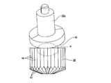
- FIG. The molding punch 39 is formed in a substantially cylindrical shape as a whole, and has the same number of machining teeth 44, 44 as the number of teeth of the hub-side face spline 21 on one end face in the axial direction at equal intervals in the circumferential direction.
- a flange portion 45 protruding radially outward is provided over the entire circumference in the axially intermediate portion of the outer peripheral surface.
- Such forming punch 39 is divided into each of the machining teeth 44, 44 in the same number as each of the machining teeth 44, 44 (the center position of the tooth base existing between the machining teeth 44, 44).
- the punch elements 46 and 46 are divided by (1).
- the shape of the forming punch 39 viewed from the axial direction is a sector shape, and an element main body 47 in which one processing tooth 44 is provided on one end face in the axial direction, and the axial direction of the outer peripheral surface of the element main body 47
- a punch element 46 composed of a projecting portion 48 provided at an intermediate portion is combined in the circumferential direction.
- the punch holding plates 49 constituting the punch lifting mechanism 40 allow the punch elements 46 and 46 to be displaced only in the axial direction with respect to the punch holding plate 49. It is supported by.
- the punch raising / lowering mechanism 40 is for raising and lowering the forming punch 39 (displacement in the axial direction of the hub main body 8), and between the punch holding plate 49, the punch holding plate 49 and the base 37.
- the hydraulic cylinders 50 and 50 provided are provided.
- the punch holding plate 49 is provided with a holding hole 51 at the center for holding the forming punch 39 in the radial direction and the circumferential direction without rattling.
- the holding hole 51 is provided with a stepped surface portion 52 at the intermediate portion in the axial direction for connecting the small diameter portion on one axial side and the large diameter portion on the other axial side.
- the dimension regarding the axial direction of the said large diameter part is larger than the dimension (thickness) regarding the axial direction of the flange part 45 of the said shaping
- an annular closing plate 53 is supported and fixed around the other axial opening of the holding hole 51 in a state where the half axial portion of the forming punch 39 is inserted into the holding hole 51.
- Such a punch holding plate 49 is supported by the hydraulic cylinders 50 and 50 so as to be movable up and down with respect to the base 37 (position adjustment in the axial direction is possible).
- each of the hydraulic cylinders 50, 50 is operated to displace the punch holding plate 49 downward, so that one axial end surface of the forming punch 39 held on the punch holding plate 49 and the caulking portion 20 The other axial end surface is brought into contact.
- the punch holding plate 49 is further displaced downward to displace the forming punch 39 in the other axial direction with respect to the holding plate 49.
- the other end surface in the axial direction of the flange portion 45 of 39 and the inner diameter side portion of one side surface in the axial direction of the closing plate 53 are brought into contact with each other. In this state, a gap 54 ⁇ see FIG.
- the axial dimension L 54 of the gap 54 is, teeth 32 of the hub-side face splines 21 so as to be the same as the tooth depth (see FIG. 12), Ya the flange portion 45 The axial dimension of the holding hole 51 is restricted.
- the ram that supports the roll 30 a is lowered, and the pressing surface 43 of the roll 30 a is brought into contact with the other axial end surface of the forming punch 39.
- the roll 30a is rotated around the central axis ⁇ of the hub body 8 in a state where the other axial end surface of the forming punch 39 is pressed with a predetermined pressing force by the pressing surface 43 of the roll 30a. That is, in a state where the other axial end surfaces of the punch elements 46, 46 constituting the forming punch 39 are directed to one axial direction and pressed by the pressing surface 43 of the roll 30a with a predetermined pressing force, the roll 30a is The hub body 8 is rotated around the central axis ⁇ .
- the punch elements 46 and 46 that are in contact with the pressing surface 43 of the roll 30a are pressed toward one axial direction, and the processing teeth 44 formed on one axial end surface of the punch elements 46 and 46, 44 is pressed against the other end surface in the axial direction of the caulking portion 20 to plastically deform the other end surface in the axial direction of the caulking portion 20.
- the punch elements 46, 46 pressed by the pressing surface 43 of the roll 30 a are arranged so that the roll 30 a rotates (revolves) around the central axis ⁇ of the hub body 8. The circumferential direction shifts in the same direction as the revolution direction.
- the plurality of punch elements (a plurality of elements) 46 are arranged so as to be independently movable at least in the axial direction.
- the punch raising / lowering mechanism (mechanism) 40 moves a part of the plurality of punch elements 46 (one punch element 46 or a small number of punch elements 46) in the axial direction to move the first region of the bearing unit 1 (workpiece). And a second part of the bearing unit 1 (workpiece) by moving another part (one punch element 46 or a small number of punch elements 46) of the plurality of punch elements 46 in the axial direction.
- a pressing mode In this plastic working, the press area changes along the circumferential direction.
- FIG. 6A is a side view showing a roll and a molding punch taken out
- FIG. 6B is an enlarged view in which a portion d in FIG. 6A is enlarged.
- the hub out of both circumferential edges of the other axial end surface of one punch element 46 out of the punch elements 46, 46.
- the rotation direction of the roll 30a about the central axis ⁇ of the main body 8 (the direction of the arrow ⁇ in FIG. 6B) in the state where the rear edge ⁇ is pressed by the pressing surface 43 of the roll 30a.
- the rotational side rear surface of the roll 30a centered on the central axis ⁇ of the hub body 8
- the central axis ⁇ and the roll Punch element existing on the front side in the rotation direction of the roll 30a around the central axis ⁇ of the one punch element 46 in a state where a virtual plane including the central axis ⁇ of 30a exists on the same plane
- the side edge ⁇ on the one punch element 46 side and the pressing surface 46 of the roll 30a are in contact or close to each other (that is, the rotation of the roll).
- the other end surface in the axial direction of the punch element that is adjacent to the front side in the direction is not strongly pressed).
- the pressing amount in the axial direction of the hub body is adjusted.
- FIG. 7A schematically shows a cross section of a contact portion between the pressing surface 43 of the roll 30 a and one axial end surface of the forming punch 39.
- FIG. 7B shows a state in which FIG. 7A is viewed from the left. That is, FIG. 7B shows the outer shape of the pressing surface 43 of the roll 30a, the origin, the radially outer side of the contact portion between the pressing surface 43 of the roll 30a and one axial end surface of the forming punch 39.
- the maximum value L 46 of the width of the punch element 46, 46 (the width in the circumferential direction of the forming punch 39), when the total number of each of these punch elements 46, 46 is N, the following (3) It is expressed by a formula.
- the width L 46 represented by the equation (3) into the equation (2), the central axis of the circumferentially opposite side edges of the other axial end surface of the one punch element 46 can be obtained.
- the side edge ⁇ on the one punch element 46 side, and the roll Pressing amount ⁇ d max at which the pressing surface 43 of 30a does not come into contact (the upper limit value of the pressing amount ⁇ d of each of the punch elements 46 and 46 per rotation around the central axis ⁇ of the hub body 8 of the roll 30a) Can be obtained approximately.
- the pressing amount ⁇ d is adjusted to 0.13 to 0.3 [mm].
- the roll 30a is supported so as to be able to rotate (rotate) about its own central axis ⁇ . Therefore, when the roll 30a is rotated about the central axis ⁇ of the hub body 8, the roll 30a is based on the frictional engagement between the pressing surface 43 of the roll 30a and the other axial end surface of the forming punch 39. 30a rotates (rotates) about its own central axis ⁇ .
- the manufacturing cost can be reduced while ensuring the durability of the wheel support rolling bearing unit 1. That is, in the case of this embodiment, the other axial end surface of the molding punch 39 is set to the roll 30a in a state where the one axial end surface of the molding punch 39 is opposed to the other axial end surface of the caulking portion 20.
- the roll 30 a is rotated about the central axis ⁇ of the hub body 8 while being pressed by the pressing surface 43. Accordingly, the hub side face is pressed against the other axial end surface of the caulking portion 20 by pressing the processing teeth 44, 44 formed on one axial end surface of the molding punch 39 against the other axial end surface of the caulking portion 20.
- the spline 21 is formed.
- the punch elements 46 and 46 constituting the forming punch 39 can only be displaced in the axial direction. Therefore, even if the other axial end surfaces of the punch elements 46, 46 are pressed by the pressing surface 43 of the roll 30a while rotating the roll 30a around the central axis ⁇ of the hub body 8,
- the tooth surfaces of the processing teeth 44, 44 are not inclined with respect to the tooth surfaces of the teeth 32 constituting the hub-side face spline 21. Accordingly, it is possible to prevent the occurrence of local contact between the tooth surfaces of the processed teeth 44 and 44 and the axial end surfaces of the caulking portions 20 such that the tooth surfaces of the teeth 32 are locally plastically deformed. .
- each tooth 32 can be improved, and the hub-side face spline 21 and the joint-side face spline 26 (see FIG. 9) formed on the constant velocity joint outer ring 2 are engaged with each other.
- the contact area between the tooth surfaces of the teeth 32 constituting the hub-side face spline 21 and the teeth constituting the joint-side face spline 26 can be sufficiently increased.
- the pressing surface 43 of the roll 30a is directed toward the other end surface in the axial direction of the caulking portion 20 via the forming punch 39.
- the pressing force (pressing force) F can be prevented from becoming excessively large.
- the roll 30a centering on the central axis ⁇ among both circumferential edges of the other axial end face of the punch element 46 of the punch elements 46, 46.
- the inclination angle ⁇ of the central axis ⁇ of the roll 30a with respect to the central axis ⁇ of the hub body 8 exceeds 30 degrees, the pressing surface 43 of the roll 30a and the molding There is a possibility that the contact area with the other end surface in the axial direction of the punch 39 is reduced, the contact surface pressure between these two surfaces is excessively increased, and it is difficult to ensure the durability of the pressing surface 43 of the roll 30a. . Therefore, in the present embodiment, the inclination angle ⁇ is set to 30 degrees or less.
- the outer peripheral surface of the molding punch is not provided with a flange portion protruding radially outward, and the outer diameter of the outer peripheral surface of the molding punch is not changed in the axial direction.
- One cylindrical surface can also be used. That is, the molding punch is a combination of a plurality of punch elements 46a provided with processing teeth 44 on one axial end face as shown in FIGS. 8A to 8C.
- 8A is a view similar to FIG. 5A showing another example of the punch element
- FIG. 8B is a view similar to FIG. 5B showing another example of the punch element
- FIG. 8C is a view different from the punch element. It is a figure similar to FIG. 5C which shows an example.
- the displacement amount of the roll 30a in the axial direction of the hub body 8 is detected, and when the displacement amount becomes the same as the tooth height of the teeth 32 constituting the hub-side face spline 21, Processing for forming the hub-side face spline 21 is completed.
- the other axial end surface of one punch element 46 is used.
- the one punch in the state where the rotation direction rear side edge of the roll 30a centering on the central axis ⁇ of the hub body 8 is pressed by the pressing surface 43 of the roll 30a.
- the circumferential edges on the other end face in the axial direction of the punch element 46 that is adjacent to the front side in the rotational direction of the roll 30a (left side in FIG.
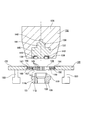
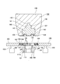
- FIG. 14 is a sectional view showing a part of the processing apparatus according to the second embodiment of the present invention in a state before starting the processing for forming the caulking portion.
- FIG. 15 is a schematic side view of a processing apparatus, with a part omitted, in one example of the oscillating press apparatus according to the second embodiment.
- FIG. 16 shows an example of the oscillating press device according to the second embodiment, in which a part of the processing device is caulked to the other axial end surface of the cylindrical portion of the hub body following the state shown in FIG. It is sectional drawing shown in the state which contacted the lower end surface of the shaping
- FIG. 17 shows an example of the oscillating press device according to the second embodiment, in which a part of the processing device is placed on the upper end surface of the caulking portion molding die following the state shown in FIG. It is sectional drawing shown in the state contact
- FIG. 18 shows a state after processing the cylindrical portion of the hub body into a caulking portion in a part of the processing device in one example of the oscillating press device of the second embodiment, following the state shown in FIG. It is sectional drawing shown by.
- FIG. 19A is an enlarged view of a portion a in FIG. 17 showing an example of the oscillating press device of the second embodiment.
- FIG. 19B is an enlarged view of a portion b in FIG. FIG.
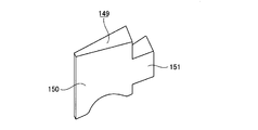
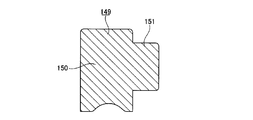
- FIG. 20A is a perspective view showing one mold element taken out from an example of the oscillating press device of the second embodiment.
- FIG. 20B is a plan view of the mold element of FIG. 20A as viewed from above.
- 20C is a cross-sectional view corresponding to the line cc in FIG. 20B.
- the outer ring 103 and the hub 104 (the hub main body 108 having the inner ring raceway 111a on one axial side on the outer peripheral surface in the axial direction, and An inner ring 109) having an inner ring raceway 111b on the other side in the axial direction on the outer peripheral surface, and a plurality of rolling elements 105, 105, and a caulking portion 120 is formed on the inner end in the axial direction of the hub body 108, Further, the wheel support rolling bearing unit 101 in which the hub-side face spline 121 is formed on the other end face in the axial direction of the caulking portion 120 will be described.
- the cylindrical portion 119 provided at the other axial end portion of the hub body 108 is subjected to plastic working so that the caulking portion 120 (the caulking portion 120 before the hub-side face spline 121 is formed) is formed.
- a method of forming will be described. Manufacturing method and assembling method of each member constituting the wheel supporting rolling bearing unit 101 until just before the caulking portion 120 is formed, and formation of the hub-side face spline 121 after the caulking portion 120 is formed Since the method is the same as a widely known method including the assembly method described above, the description thereof is omitted in this embodiment.
- the vertical direction means the vertical direction of FIGS. 14 to 19B.
- the vertical direction in FIGS. 14 to 19B does not necessarily coincide with the vertical direction during processing.
- a processing device (manufacturing device) for forming the caulking portion 120 includes a base 130 (shown only in FIG. 15), and a holder 131 (shown only in FIG. 15) supported and fixed on the upper surface of the base 130. , A pressing unit 132, a pressing unit drive mechanism 133, a caulking part molding die 134, a molding die lifting mechanism 135, and a control device (not shown).
- the control device includes a circuit and is configured to control the entire swing press device 36 in an integrated manner.
- the holder 131 aligns the central axis of the hub main body 108 in the vertical direction (vertical direction), and the wheel bearing rolling bearing unit 101 with the other axial end of the hub main body 108 facing upward. Is to hold.
- the pressing unit 132 includes a head 136, a roller jig 137, and a plurality of (for example, 2 to 6) rollers 138 and 138, and is disposed above the hub body 108.
- the central axis of the head 136 coincides with the central axis of the hub body 108.
- the head 136 has a bottomed mounting hole 139 that opens at the center in the radial direction of the lower end surface.
- the roller jig 137 is formed in a stepped columnar shape, with a large-diameter columnar portion 140 at the lower end, an intermediate-diameter columnar portion 141 at the middle in the vertical direction, and a small-diameter columnar portion 142 at the upper end. Prepare for the same axis.
- the roller jig 137 has holding recesses 143 and 143 at a plurality (the same number as the rollers 138 and 138) at equal intervals in the circumferential direction of the lower end surface of the large-diameter cylindrical portion 140. Yes.
- Such a roller jig 137 is fixedly mounted in the mounting hole 139 of the head 136.
- the mounting hole 139 is a bottomed stepped hole.
- An outer diameter side retaining ring groove (not shown) is formed on the inner peripheral surface of the small diameter hole provided at the upper end portion of the mounting hole 139, and the outer diameter side retaining ring groove has a retaining ring (not shown).
- a radially outer half is housed.
- the diameter dimension of the groove bottom of the said outer diameter side retaining ring groove is larger than the outer diameter dimension in the free state of the said retaining ring.
- the retaining ring is elastically expanded, and then the retaining ring is formed on the outer peripheral surface of the small-diameter cylindrical portion 142.
- the retaining ring is aligned with the side retaining ring groove, the retaining ring is elastically restored, and the retaining ring is spanned between the outer diameter side and inner diameter side retaining ring grooves, whereby the mounting hole 139 is provided. This prevents the roller jig 137 from coming out.
- the head 136 and the roller jig are formed by spline-engaging the inner peripheral surface of the medium-diameter hole provided in the vertical middle portion of the mounting hole 139 and the outer peripheral surface of the medium-diameter cylindrical portion 141. Torque transmission to and from 137 is possible. Further, the large-diameter cylindrical portion 140 is fitted in the large-diameter hole provided at the lower end of the mounting hole 139 without rattling.
- the pressing unit drive mechanism 133 is for rotating and moving up and down (displacement in the axial direction of the hub main body 108) of the pressing unit 132, and is supported by a support column 166 fixed to the base 130. .
- Such a pressing unit drive mechanism 133 is driven by an electric motor 144 to directly rotate (without a speed reduction mechanism), and a spindle 145 arranged in the vertical direction, and a hydraulic type that drives the spindle 145 up and down. Cylinder 146.
- a head 136 (not shown in FIG. 15) of the pressing unit 132 is attached and fixed to the lower end portion of the spindle 145.
- the caulking part forming die 134 is configured in a substantially cylindrical shape as a whole, and is disposed in a portion between the hub main body 108 and the pressing unit 132 in the vertical direction.
- the caulking portion forming die 134 has a shape that matches the other end surface in the axial direction of the caulking portion 120 at a lower end surface that is one end surface in the axial direction (a circular concave surface having a substantially arc-shaped cross section). 147 is provided, and a flange portion 148 projecting radially outward is provided at the axially intermediate portion of the outer peripheral surface over the entire circumference.
- Such a caulking portion molding die 134 has a plurality of molding elements 149 and 149 (for example, 20 to 40) divided in the circumferential direction (for example, in the circumferential direction around the central axis of the hub body 108). It is configured by combining a plurality of mold elements 149, 149) arranged side by side.
- the caulking part forming die 134 has a fan-shaped shape when viewed from the axial direction, and an element main body 150 having a lower end surface provided with a part in the circumferential direction of the processed surface 147, and an outer periphery of the element main body 150
- the mold element 149 is formed by combining in a circumferential direction a molding element 149 formed from a protruding portion 51 which is a part in the circumferential direction of the flange portion 148 provided at an axially intermediate portion of the surface.
- the caulking part mold 134 having such a configuration allows the respective mold elements 149 and 149 to be axially displaced independently from each other with respect to the holding plate 152 constituting the mold lifting mechanism 135. It is supported by.
- the mold raising / lowering mechanism 135 is for raising and lowering the caulking part molding die 134 (displacement in the axial direction of the hub main body 108), and includes a holding plate 152, the holding plate 152, and the base 130. And hydraulic or pneumatic cylinders 153 and 153 provided therebetween.
- the holding plate 152 is arranged in the horizontal direction, and a holding hole 154 for holding the caulking part molding die 134 in the radial direction and the circumferential direction is provided in the center part.
- the holding hole 154 is a stepped hole in which a lower small diameter portion and an upper large diameter portion are made continuous by a step surface portion 155.
- the axial dimension of the large diameter part is larger than the axial dimension of the flange part 148 of the caulking part molding die 134.
- an inward flange portion 167 is provided in the upper half portion of the large diameter portion.
- the holding plate 152 has a configuration that can be divided into two in the radial direction.
- annular holding plate 156 is fitted into the large diameter part of the holding hole 154.
- the center hole of the pressing plate 156 is a stepped hole in which the upper small diameter portion and the lower large diameter portion are made continuous by the step surface portion 157.
- An outward flange 168 is provided in the lower half of the outer peripheral surface of the holding plate 156.
- the upper half portion of the outer peripheral surface of the holding plate 156 is guided by the inner peripheral surface of the inward flange portion 167 so as to be able to be displaced in the axial direction without shaking in the radial direction.
- the holding plate 156 is biased in a direction approaching the stepped surface portion 155 of the holding hole 154 by a biasing spring 158 schematically shown in FIGS. 19A and 19B. Has been.
- the flange portion 148 of the caulking portion molding die 134 in the state before the start of forming the caulking portion 120 is caused by the elasticity of the biasing spring 158. It is sandwiched between the step surface portion 155 and the step surface portion 157 of the holding plate 156. In this state, a gap is formed between the upper surface of the outward flange 168 and the lower surface of the inward flange 167.
- the holding plate 152 as described above is supported by the cylinders 153 and 153 so as to be movable up and down with respect to the base 130.
- the holding plate 152 includes a machining surface 147 provided at a lower end surface of the caulking portion forming die 134 and an axial other end surface of the wheel supporting rolling bearing unit 101 held by the holder 131 (the hub body).
- the other end surface in the axial direction of the cylindrical portion 119 of the cylinder 108 is positioned above the vertical direction so as not to abut.
- the flange portion 148 of the caulking portion molding die 134 is formed between the step surface portion 155 of the holding hole 154 and the step surface portion 157 of the holding plate 156 by the elasticity of the biasing spring 158. It is in a state of being sandwiched between them. Further, the wheel support rolling bearing unit 101 holds the holder 131 in a state where the central axis of the hub body 108 coincides with the vertical direction, and the other axial end of the hub body 108 faces upward. Keep it.
- the pressing unit 132 is further displaced downward based on the operation of the pressing unit drive mechanism 133.
- the pressing unit 132 is rotationally driven in a state where the outer peripheral surfaces of the rollers 138 and 138 are pressed against the upper end surface of the caulking portion molding die 134, that is, the upper end surfaces of the molding die elements 149 and 149 so as to roll.
- the rollers 138 and 138 roll in the circumferential direction.
- each of the plurality of mold elements (plural elements) 149 is arranged to be independently movable at least in the axial direction.
- the pressing unit drive mechanism (mechanism) 133 moves part of the plurality of mold elements 149 (one mold element 149 or a small number of mold elements 149) in the axial direction to move the hub main body 108 (workpiece). ) And a mode in which another part of the plurality of mold elements 149 is moved in the axial direction to press the second region of the hub body 108 (workpiece). In this plastic working, the press area changes along the circumferential direction.
- the axial dimension L 159 of the gap 159 is such that when the caulking portion 120 is formed, one roller 138 is arranged in the circumferential direction on the upper end surface of each mold element 149, 149. Each time it passes once, it is made larger than the downward displacement amount (working stroke) of the respective mold elements 149, 149.
- the cylinders 153 and 153 prevent the gap 159 from disappearing by continuously applying a downward force to the holding plate 152.
- the processing for forming the caulking portion 120 as described above ends when a certain time has elapsed after the plastic processing of the cylindrical portion 119 is started. Until the predetermined time elapses, a press load (a load for displacing the press unit 132 downward) of the cylinder 146 (see FIG. 15) constituting the press unit drive mechanism 133 is a predetermined value. And when the pressing unit 132 is in a predetermined position, it is determined that the caulking portion 120 is properly formed. On the other hand, when the press load does not reach the predetermined value until the predetermined time elapses, or when the pressing unit 132 is not in the predetermined position, the caulking portion 120 is appropriate. It was determined that it was not formed.
- the press load 132 reaches the predetermined position while the press load reaches the predetermined value in the processing for forming the caulking portion 120 as described above. Can be terminated after a predetermined time has elapsed.
- the shaft of the hub main body 108 is processed when the axial other end portion (the caulking portion 120) of the hub main body 108 is processed. Uneven load applied to the other end in the direction can be reduced or substantially zero. That is, in the case of the present embodiment, when the caulking portion 120 is formed, the load (working force) applied to the cylindrical portion 119 provided at the other axial end portion of the hub body 108 is equal in the circumferential direction. Loads at equal intervals in the circumferential direction are applied from the arranged rollers 138 and 138 via some of the mold elements 149 and 149.
- the caulking portion 120 can be formed without substantially applying an offset load to the other axial end surface of the cylindrical portion 119. Therefore, after the caulking portion 120 is formed, the force that the caulking portion 120 suppresses the other end surface in the axial direction of the inner ring 109 can be easily made uniform over the entire circumference.
- FIG. 21 is sectional drawing which shows a part of processing apparatus regarding the 3rd Embodiment of this invention in the state before starting the process which forms a hub side face spline.
- FIG. 22 shows a part of the processing apparatus of the third embodiment in which the lower end surface of the face spline mold is brought into contact with the other end surface in the axial direction of the caulking portion of the hub body, following the state shown in FIG. It is sectional drawing shown in a state.
- FIG. 21 is sectional drawing which shows a part of processing apparatus regarding the 3rd Embodiment of this invention in the state before starting the process which forms a hub side face spline.
- FIG. 22 shows a part of the processing apparatus of the third embodiment in which the lower end surface of the face spline mold is brought into contact with the other end surface in the axial direction of the caulking portion of the hub body, following the state shown in FIG. It is sectional drawing shown in a state.
- FIG. 21 is sectional drawing which shows
- FIG. 23 is a cross-sectional view showing a part of the processing apparatus of the third embodiment in a state in which a plurality of rollers are brought into contact with the upper end surface of the face spline mold after the state shown in FIG. is there.
- 24 is a cross-sectional view showing a part of the processing apparatus of the third embodiment in a state after the caulking portion of the hub body is processed into a hub-side face spline following the state shown in FIG.
- FIG. 25A is an enlarged view of a portion d in FIG. 23 of the third embodiment.
- FIG. 25B is an enlarged view of an e portion in FIG. 24 of the third embodiment.
- FIG. 26A is a perspective view showing one mold element according to the third embodiment.
- FIG. 26B is a plan view of the mold element of FIG. 26A of the third embodiment as viewed from above.
- FIG. 26C is a cross-sectional view corresponding to the line ff in FIG. 26B of the third embodiment.
- the outer ring 103, the hub 104 (the hub main body 108 having the inner ring raceway 111a on one axial side on the outer circumferential surface in the axial direction, and the outer circumference And an inner ring 109) having an inner ring raceway 111b on the other side in the axial direction, and a plurality of rolling elements 105, 105, and a caulking portion 120 is formed at the inner end of the hub body 108 in the axial direction.
- a wheel support rolling bearing unit 101 in which a hub-side face spline 121 is formed on the other end surface in the axial direction of the caulking portion 120 will be described.
- a method of forming the hub-side face spline 121 by performing plastic working on the caulking portion 120 formed at the other axial end portion of the hub body 108 will be described.
- the manufacturing method and assembling method (including the method for forming the caulking portion 120) of each member constituting the wheel supporting rolling bearing unit 101 until immediately before the hub-side face spline 121 is formed have been described above. Since this method is the same as a widely known method including an assembling method and the manufacturing method of the first example of the above-described embodiment, the description thereof is omitted in this embodiment.
- the vertical direction means the vertical direction of FIGS.
- the vertical direction in FIGS. 21 to 25B does not necessarily coincide with the vertical direction during processing.
- the processing device (manufacturing device) for forming the hub-side face spline 121 includes a face spline forming die 160 as a forming die instead of the caulking portion forming die 134 (see FIGS. 14 and 16 to 18). Is different from the processing apparatus of the second embodiment described above. About the structure and operation
- the face spline molding die 160 is formed in a substantially cylindrical shape as a whole, and the processing teeth 161, 161 having the same number as the number of teeth of the hub side face spline 121 are circular on the lower end surface which is one end surface in the axial direction.
- a flange portion 162 that is formed at an equal pitch in the circumferential direction and protrudes radially outward is provided at the axially intermediate portion of the outer circumferential surface over the entire circumference.
- Such a face spline mold 160 has a plurality of mold elements 163, 163 (for example, 20 to 40 in the present embodiment. In this embodiment, the mold elements 163, 163 (the same number as the processing teeth 161, 161) are divided.
- the face-spline mold 160 has a fan-shaped shape viewed from the axial direction and an element main body 164 provided with one processing tooth 161 on the lower end surface, and an axis of the outer peripheral surface of the element main body 164.
- the mold element 163 is formed by combining in the circumferential direction a molding element 163 that is provided at a middle portion in the direction and includes a projecting portion 165 that is a part in the circumferential direction of the flange portion 162.
- the face spline molding die 160 is provided at the center of the holding plate 152 constituting the molding die lifting mechanism 135.
- the respective mold elements 163 and 163 are held without shakiness in the radial direction and the circumferential direction in a state in which they can be independently displaced in the axial direction.
- the flange portion 162 of the face spline mold 160 changes the posture of the face spline mold 160.
- the holding plate 152 is held by processing teeth 161 and 161 provided on a lower end surface of the face spline mold 160 and a holder 131 (see FIG. 15).
- the wheel-supporting rolling bearing unit 101 is positioned above the other end surface in the axial direction (the other end surface in the axial direction of the caulking portion 120) so as not to contact.
- the flange portion 162 of the face spline mold 160 is formed between the step surface portion 155 of the holding hole 154 and the step surface portion 157 of the holding plate 156 by the elasticity of the biasing spring 158. It is in a state of being sandwiched between them. Further, the wheel support rolling bearing unit 101 holds the holder 131 in a state where the central axis of the hub body 108 coincides with the vertical direction, and the other axial end of the hub body 108 faces upward. Keep it.
- a gap 159 a in the axial direction is formed between the lower surface of the flange portion 162 and the stepped surface portion 155 of the holding hole 154.
- the axial dimension L 159a of the gap 159a will be described later.
- the pressing unit 132 is further displaced downward to The pressing unit 132 is rotationally driven while the outer peripheral surfaces of the rollers 138 and 138 are pressed against the upper end surface of the face spline mold 160, that is, the upper end surfaces of the molding element 163 and 163, respectively.
- the rollers 138 and 138 roll in the circumferential direction.
- the rolling teeth of the rollers 138 and 138 are sequentially pressed against the other side surface in the axial direction of the mold elements 163 and 163, so that the processing teeth 161 and 161 of the mold elements 163 and 163 are pressed.
- the other end surface in the axial direction of the caulking portion 120 is plastically deformed to form the hub-side face spline 121.
- the axial dimension L 159a of the gap 159a is such that when the hub-side face spline 121 is formed, one roller 138 is attached to the upper end surface of each of the mold elements 163 and 163. Each time it passes once in the circumferential direction, it is larger than the downward displacement amount (machining stroke) of the respective mold elements 163 and 163.
- the cylinders 153 and 153 prevent the gap 159a from disappearing by continuously applying a downward force to the holding plate 152.
- the processing for forming the hub-side face spline 121 as described above ends when a certain time has elapsed since the plastic processing of the caulking portion 120 is started. Until the predetermined time elapses, a press load (a load for displacing the press unit 132 downward) of the cylinder 146 (see FIG. 15) constituting the press unit drive mechanism 133 is a predetermined value. And when the pressing unit 132 is in a predetermined position, it is determined that the hub-side face spline 121 is properly formed.
- the hub-side face spline 121 is used. Is determined not to be properly formed.
- the processing for forming the hub-side face spline 121 as described above is performed while the pressing load reaches the predetermined value and the pressing unit 132 is positioned at a predetermined position. Can be continued until a predetermined time elapses.
- the hub main body 108 is processed when the other axial end portion (the hub-side face spline 121) of the hub main body 108 is processed.
- the offset load applied to the other axial end can be reduced or substantially zero. That is, in the case of this embodiment, when forming the hub-side face spline 121, the load (working force) applied to the other end surface in the axial direction of the caulking portion 120 is the rollers arranged at equal intervals in the circumferential direction. From 138 and 138, it becomes the load of the circumferential direction equal intervals applied via some shaping
- the hub-side face spline 121 can be formed without substantially applying an offset load to the other axial end surface of the caulking portion 120. Therefore, after the hub-side face spline 121 is formed, the force that the caulking portion 120 suppresses the other end surface in the axial direction of the inner ring 109 can be easily made uniform over the entire circumference.
- the eccentric load applied to the other axial end of the hub body is reduced or substantially zero. It is possible to provide a method and apparatus for manufacturing a rolling bearing unit that can be made.
- the axial end of the molding punch has a central axis that is inclined with respect to the central axis of the hub body, with the axial end of the molding punch facing the other axial end of the caulking portion.
- the roll is rotated around the central axis of the hub body while being pressed by the pressing surface of the roll.
- the processing teeth formed on one axial end surface of the forming punch are pressed against the other axial end surface of the caulking portion, and the hub side face spline is formed on the other axial end surface of the caulking portion.
- the plurality of punch elements constituting the forming punch are allowed to be displaced in the axial direction and are prevented from being displaced in the circumferential direction.
- the processing teeth can be prevented from being inclined with respect to the tooth surfaces of the teeth constituting the hub side face spline. Occurrence of local contact between the processed surface of the roll and the axial end surface of the caulking portion, in which the tooth surface of the tooth is locally plastically deformed, can be prevented. Accordingly, the straightness of these teeth can be improved, and the durability of the bearing unit can be sufficiently ensured. In addition, it is possible to suppress the force that presses the pressing surface of the roll toward the other side in the axial direction, and to prevent the processing apparatus used for processing for forming the hub-side face spline from being enlarged, thereby reducing the manufacturing cost. Increase can be suppressed.
- a load (working force) applied to the cylindrical portion provided at the other axial end portion of the hub body is a circle centered on the central axis of the hub body. Loads at a plurality of locations in the circumferential direction are applied from a plurality of rollers arranged at a plurality of locations in the circumferential direction via some of the molding elements. For this reason, compared to the case where the caulking portion is processed by swing forging, the uneven load applied to the cylindrical portion provided at the other axial end portion of the hub body can be reduced or substantially zero.
- the load (working force) applied to the caulking portion provided at the other axial end of the hub body is a circumferential direction around the center axis of the hub body. Loads at a plurality of locations in the circumferential direction are applied from a plurality of rollers arranged at a plurality of locations via some of the mold elements. For this reason, it is possible to reduce or substantially eliminate the uneven load applied to the caulking portion provided at the other axial end portion of the hub body as compared with the case where the hub side face spline is processed by swing forging.
- the manufacturing method of the present invention can be implemented not only for the rolling bearing units described in the above-described embodiments but also for various rolling bearing units that satisfy the requirements described in the claims.
- the invention characterized by the method of forming the caulking portion is implemented for a rolling bearing unit that does not have a hub-side face spline on the other axial end surface of the caulking portion after completion. You can also.
- a mode in which a plurality of rollers are arranged in a rotationally symmetric positional relationship around the central axis of the hub main body on a circumference around the central axis of the hub main body is a circle.
- the caulking portion (hub-side face spline) can be formed without substantially applying an offset load to the cylindrical portion (caulking portion) of the hub body.
Landscapes
- Engineering & Computer Science (AREA)
- Mechanical Engineering (AREA)
- General Engineering & Computer Science (AREA)
- Rolling Contact Bearings (AREA)
Abstract
L'invention concerne un procédé pour la fabrication d'une unité de palier à roulement, dans lequel une surface d'extrémité axiale d'un poinçon de formage (46) est positionnée pour être en regard de l'autre surface d'extrémité axiale d'une section (20) à frapper, le poinçon de formage (46) étant formé par combinaison d'une pluralité d'éléments de poinçon (46, 46) séparés circonférentiellement, chacun d'eux pouvant être déplacé axialement et le déplacement circonférentiel de chacun d'eux étant empêché, le poinçon de formage (46) ayant des dents de travail (44, 44) formées sur sa surface d'extrémité axiale. Dans l'état susmentionné, un rouleau (30a) ayant un axe central (β) incliné par rapport à l'axe central (α) d'un corps de moyeu (8) est amené à tourner autour de l'axe central (α) alors que la surface de pression (43) du rouleau (30a) appuie sur l'autre surface d'extrémité axiale du poinçon de formage (46).
Priority Applications (4)
| Application Number | Priority Date | Filing Date | Title |
|---|---|---|---|
| CN201680040787.1A CN107848014B (zh) | 2015-07-13 | 2016-07-12 | 轴承单元的制造方法以及制造装置 |
| EP16824461.4A EP3323525B1 (fr) | 2015-07-13 | 2016-07-12 | Procédé et dispositif pour la fabrication d'une unité de palier |
| US15/572,581 US10557505B2 (en) | 2015-07-13 | 2016-07-12 | Method and device for manufacturing bearing unit |
| US16/700,171 US11162538B2 (en) | 2015-07-13 | 2019-12-02 | Method and device for manufacturing bearing unit |
Applications Claiming Priority (4)
| Application Number | Priority Date | Filing Date | Title |
|---|---|---|---|
| JP2015-139543 | 2015-07-13 | ||
| JP2015139543A JP6222177B2 (ja) | 2015-07-13 | 2015-07-13 | 転がり軸受ユニットの製造方法、車両の製造方法 |
| JP2015-196510 | 2015-10-02 | ||
| JP2015196510A JP6222197B2 (ja) | 2015-10-02 | 2015-10-02 | 転がり軸受ユニットの製造方法及び製造装置、車両の製造方法 |
Related Child Applications (2)
| Application Number | Title | Priority Date | Filing Date |
|---|---|---|---|
| US15/572,581 A-371-Of-International US10557505B2 (en) | 2015-07-13 | 2016-07-12 | Method and device for manufacturing bearing unit |
| US16/700,171 Division US11162538B2 (en) | 2015-07-13 | 2019-12-02 | Method and device for manufacturing bearing unit |
Publications (1)
| Publication Number | Publication Date |
|---|---|
| WO2017010481A1 true WO2017010481A1 (fr) | 2017-01-19 |
Family
ID=57757370
Family Applications (1)
| Application Number | Title | Priority Date | Filing Date |
|---|---|---|---|
| PCT/JP2016/070551 Ceased WO2017010481A1 (fr) | 2015-07-13 | 2016-07-12 | Procédé et dispositif pour la fabrication d'une unité de palier |
Country Status (4)
| Country | Link |
|---|---|
| US (2) | US10557505B2 (fr) |
| EP (1) | EP3323525B1 (fr) |
| CN (1) | CN107848014B (fr) |
| WO (1) | WO2017010481A1 (fr) |
Cited By (3)
| Publication number | Priority date | Publication date | Assignee | Title |
|---|---|---|---|---|
| CN108006086A (zh) * | 2017-12-31 | 2018-05-08 | 无锡华洋滚动轴承有限公司 | 自定位等分压装装置 |
| US20200392988A1 (en) * | 2018-02-26 | 2020-12-17 | Nsk Ltd. | Rotary machining apparatus, method of manufacturing hub unit bearing, and method of manufacturing vehicle |
| CN113976926A (zh) * | 2021-12-17 | 2022-01-28 | 中国船舶重工集团公司第十二研究所 | 一种双止推滑动轴承在精加工阶段的加工装置及方法 |
Families Citing this family (10)
| Publication number | Priority date | Publication date | Assignee | Title |
|---|---|---|---|---|
| EP3603841B1 (fr) * | 2017-03-29 | 2021-05-19 | Fuji Shoji Co., Ltd. | Dispositif de contrainte de la bague interne d'un roulement de moyeu de véhicule |
| CN110523903B (zh) * | 2019-08-22 | 2022-06-03 | 重庆伊洛美克动力总成有限公司 | 一种台阶式齿毂成型机构及其成型方法 |
| CN110805622A (zh) * | 2019-11-28 | 2020-02-18 | 浙江陀曼精密机械有限公司 | 一种轴承套圈打入机构 |
| IT202000015166A1 (it) | 2020-06-25 | 2021-12-25 | Skf Ab | Attrezzatura e metodo migliorati per la formatura di una dentatura frontale su un anello interno di un mozzo ruota |
| IT202000024166A1 (it) * | 2020-10-14 | 2022-04-14 | Skf Ab | Attrezzatura e metodo per la formatura di una dentatura frontale su un anello interno di un mozzo ruota e dentatura frontale associata |
| CN113134541A (zh) * | 2021-04-06 | 2021-07-20 | 杭州晨龙智能科技有限公司 | 冲床转盘机构和冲床 |
| IT202100008984A1 (it) * | 2021-04-12 | 2022-10-12 | Skf Ab | Metodo per la formatura di una dentatura frontale su un anello interno di un mozzo ruota e attrezzatura associata |
| CN115301885A (zh) * | 2022-09-02 | 2022-11-08 | 人本股份有限公司 | 用于轮毂轴承端面花键加工的旋铆装置 |
| CN117620018A (zh) * | 2023-11-15 | 2024-03-01 | 杭州首连电气有限公司 | 表带触指的铆接方法及表带触指 |
| CN120502979B (zh) * | 2025-07-22 | 2025-10-31 | 万向钱潮股份公司 | 一种轴承加工方法及系统 |
Citations (6)
| Publication number | Priority date | Publication date | Assignee | Title |
|---|---|---|---|---|
| US1625131A (en) * | 1924-01-26 | 1927-04-19 | Timken Roller Bearing Co | Die |
| JPS63224833A (ja) * | 1987-03-12 | 1988-09-19 | Aida Eng Ltd | 成形用金型 |
| JPH0381239U (fr) * | 1989-12-05 | 1991-08-20 | ||
| JPH07317755A (ja) * | 1994-05-20 | 1995-12-08 | Ntn Corp | ハブユニット軸受外輪およびその製造方法 |
| JP2002254901A (ja) * | 2000-12-26 | 2002-09-11 | Ntn Corp | 車輪軸受装置およびその製造方法 |
| JP2013224746A (ja) * | 2013-07-16 | 2013-10-31 | Ntn Corp | 固定式等速自在継手の外側継手部材 |
Family Cites Families (15)
| Publication number | Priority date | Publication date | Assignee | Title |
|---|---|---|---|---|
| US3834501A (en) | 1971-11-17 | 1974-09-10 | Daikin Mfg Co Ltd | Dual spring device for preventing improper disengagement of clutch |
| CA2338376A1 (fr) | 1998-07-24 | 2000-02-03 | Masateru Shiraishi | Procede de forgeage par matrices |
| JP4067751B2 (ja) | 2000-09-04 | 2008-03-26 | Ntn株式会社 | 車輪軸受装置の加締方法 |
| JP2004162913A (ja) | 2002-10-21 | 2004-06-10 | Nsk Ltd | 車輪支持用転がり軸受ユニットの製造方法及び製造装置 |
| JP2006305599A (ja) | 2005-04-28 | 2006-11-09 | Honda Motor Co Ltd | 傘歯車の鍛造成形方法及び装置 |
| JP5261023B2 (ja) | 2008-05-13 | 2013-08-14 | Ntn株式会社 | 車輪用軸受装置の加工方法 |
| JP5355938B2 (ja) | 2008-06-09 | 2013-11-27 | Ntn株式会社 | 駆動車輪用軸受装置 |
| US8096045B2 (en) * | 2008-12-17 | 2012-01-17 | Il Jin Global Co., Ltd. | Device and method for manufacturing wheel bearing assembly |
| CN101623736A (zh) * | 2009-08-06 | 2010-01-13 | 上海交通大学 | 薄壁钣金件三维曲面模压成形模具及其压模方法 |
| CN103313809B (zh) * | 2011-01-07 | 2016-10-12 | 丰田自动车株式会社 | 滚子卷边装置 |
| CN103429780B (zh) | 2011-03-01 | 2017-05-17 | 斯奈克玛 | 用于制造金属部件,诸如涡轮发动机叶片加强件的方法 |
| ITTO20110700A1 (it) | 2011-07-29 | 2013-01-30 | Skf Ab | Metodo per la formatura di una dentatura frontale su un anello interno di un mozzo ruota |
| ITTO20110703A1 (it) | 2011-07-29 | 2013-01-30 | Skf Ab | Attrezzatura per la formatura di una dentatura frontale, in particolare su un anello interno di un mozzo ruota |
| ITTO20110701A1 (it) | 2011-07-29 | 2013-01-30 | Skf Ab | Metodo per la formatura di una dentatura frontale su un anello interno di un mozzo ruota |
| CN203453296U (zh) | 2012-07-05 | 2014-02-26 | 日本精工株式会社 | 车轮支承用滚动轴承单元 |
-
2016
- 2016-07-12 EP EP16824461.4A patent/EP3323525B1/fr active Active
- 2016-07-12 WO PCT/JP2016/070551 patent/WO2017010481A1/fr not_active Ceased
- 2016-07-12 US US15/572,581 patent/US10557505B2/en active Active
- 2016-07-12 CN CN201680040787.1A patent/CN107848014B/zh active Active
-
2019
- 2019-12-02 US US16/700,171 patent/US11162538B2/en active Active
Patent Citations (6)
| Publication number | Priority date | Publication date | Assignee | Title |
|---|---|---|---|---|
| US1625131A (en) * | 1924-01-26 | 1927-04-19 | Timken Roller Bearing Co | Die |
| JPS63224833A (ja) * | 1987-03-12 | 1988-09-19 | Aida Eng Ltd | 成形用金型 |
| JPH0381239U (fr) * | 1989-12-05 | 1991-08-20 | ||
| JPH07317755A (ja) * | 1994-05-20 | 1995-12-08 | Ntn Corp | ハブユニット軸受外輪およびその製造方法 |
| JP2002254901A (ja) * | 2000-12-26 | 2002-09-11 | Ntn Corp | 車輪軸受装置およびその製造方法 |
| JP2013224746A (ja) * | 2013-07-16 | 2013-10-31 | Ntn Corp | 固定式等速自在継手の外側継手部材 |
Non-Patent Citations (1)
| Title |
|---|
| See also references of EP3323525A4 * |
Cited By (6)
| Publication number | Priority date | Publication date | Assignee | Title |
|---|---|---|---|---|
| CN108006086A (zh) * | 2017-12-31 | 2018-05-08 | 无锡华洋滚动轴承有限公司 | 自定位等分压装装置 |
| CN108006086B (zh) * | 2017-12-31 | 2023-09-15 | 无锡华洋滚动轴承有限公司 | 自定位等分压装装置 |
| US20200392988A1 (en) * | 2018-02-26 | 2020-12-17 | Nsk Ltd. | Rotary machining apparatus, method of manufacturing hub unit bearing, and method of manufacturing vehicle |
| US11732751B2 (en) * | 2018-02-26 | 2023-08-22 | Nsk Ltd. | Rotary machining apparatus, method of manufacturing hub unit bearing, and method of manufacturing vehicle |
| US11821463B2 (en) | 2018-02-26 | 2023-11-21 | Nsk Ltd. | Rotary machining device, method of manufacturing hub unit bearing and method of manufacturing vehicle |
| CN113976926A (zh) * | 2021-12-17 | 2022-01-28 | 中国船舶重工集团公司第十二研究所 | 一种双止推滑动轴承在精加工阶段的加工装置及方法 |
Also Published As
| Publication number | Publication date |
|---|---|
| EP3323525A4 (fr) | 2019-03-27 |
| US10557505B2 (en) | 2020-02-11 |
| EP3323525A1 (fr) | 2018-05-23 |
| US11162538B2 (en) | 2021-11-02 |
| US20200102987A1 (en) | 2020-04-02 |
| CN107848014B (zh) | 2021-06-29 |
| CN107848014A (zh) | 2018-03-27 |
| US20180202495A1 (en) | 2018-07-19 |
| EP3323525B1 (fr) | 2021-09-29 |
Similar Documents
| Publication | Publication Date | Title |
|---|---|---|
| WO2017010481A1 (fr) | Procédé et dispositif pour la fabrication d'une unité de palier | |
| JP6222177B2 (ja) | 転がり軸受ユニットの製造方法、車両の製造方法 | |
| JP6213528B2 (ja) | 転がり軸受ユニットの製造方法及び車両の製造方法 | |
| CN103608136B (zh) | 端面花键成形装置、端面花键成形方法、外侧联轴器构件及等速万向联轴器 | |
| JP7512977B2 (ja) | かしめアセンブリの製造方法、ハブユニット軸受の製造方法、かしめ装置、及び車両の製造方法 | |
| WO2018159670A1 (fr) | Dispositif de forgeage rotatif, procédé de forgeage rotatif, procédé de fabrication de palier de moyeu à l'aide d'un procédé de forgeage rotatif, et procédé de fabrication de véhicule | |
| JP4127266B2 (ja) | 車輪支持用転がり軸受ユニットの製造方法及び製造装置 | |
| JP6724895B2 (ja) | 軸受ユニットの製造方法及び揺動プレス装置 | |
| JP6222197B2 (ja) | 転がり軸受ユニットの製造方法及び製造装置、車両の製造方法 | |
| JP2004162913A (ja) | 車輪支持用転がり軸受ユニットの製造方法及び製造装置 | |
| JP2017106510A (ja) | 転がり軸受ユニットの製造方法及び転がり軸受ユニットの製造装置 | |
| JP2017067254A5 (fr) | ||
| US12123466B2 (en) | Staking apparatus and staking method for bearing unit, manufacturing method and manufacturing apparatus of hub unit bearing, and manufacturing method of vehicle | |
| JP6372627B2 (ja) | 車輪支持用軸受ユニットの製造方法及び製造装置、並びに車両の製造方法 | |
| JP7210719B2 (ja) | 軸受けリングを加工し、転がり軸受けを製造するための方法 | |
| WO2025210955A1 (fr) | Procédé d'assemblage par sertissage, procédé de fabrication de palier d'unité de moyeu, procédé de fabrication de véhicule, procédé de fabrication de dispositif de machine et dispositif de sertissage | |
| JP2026075114A (ja) | かしめ結合方法、ハブユニット軸受の製造方法、車両の製造方法、機械装置の製造方法、およびかしめ加工装置 |
Legal Events
| Date | Code | Title | Description |
|---|---|---|---|
| 121 | Ep: the epo has been informed by wipo that ep was designated in this application |
Ref document number: 16824461 Country of ref document: EP Kind code of ref document: A1 |
|
| WWE | Wipo information: entry into national phase |
Ref document number: 15572581 Country of ref document: US |
|
| NENP | Non-entry into the national phase |
Ref country code: DE |
|
| WWE | Wipo information: entry into national phase |
Ref document number: 2016824461 Country of ref document: EP |