WO2017010497A1 - Procédé de production pour stratifié optique - Google Patents
Procédé de production pour stratifié optique Download PDFInfo
- Publication number
- WO2017010497A1 WO2017010497A1 PCT/JP2016/070638 JP2016070638W WO2017010497A1 WO 2017010497 A1 WO2017010497 A1 WO 2017010497A1 JP 2016070638 W JP2016070638 W JP 2016070638W WO 2017010497 A1 WO2017010497 A1 WO 2017010497A1
- Authority
- WO
- WIPO (PCT)
- Prior art keywords
- thin glass
- optical
- adhesive
- optical film
- film
- Prior art date
- Legal status (The legal status is an assumption and is not a legal conclusion. Google has not performed a legal analysis and makes no representation as to the accuracy of the status listed.)
- Ceased
Links
Images
Classifications
-
- B—PERFORMING OPERATIONS; TRANSPORTING
- B32—LAYERED PRODUCTS
- B32B—LAYERED PRODUCTS, i.e. PRODUCTS BUILT-UP OF STRATA OF FLAT OR NON-FLAT, e.g. CELLULAR OR HONEYCOMB, FORM
- B32B37/00—Methods or apparatus for laminating, e.g. by curing or by ultrasonic bonding
- B32B37/12—Methods or apparatus for laminating, e.g. by curing or by ultrasonic bonding characterised by using adhesives
-
- B—PERFORMING OPERATIONS; TRANSPORTING
- B32—LAYERED PRODUCTS
- B32B—LAYERED PRODUCTS, i.e. PRODUCTS BUILT-UP OF STRATA OF FLAT OR NON-FLAT, e.g. CELLULAR OR HONEYCOMB, FORM
- B32B17/00—Layered products essentially comprising sheet glass, or glass, slag, or like fibres
- B32B17/06—Layered products essentially comprising sheet glass, or glass, slag, or like fibres comprising glass as the main or only constituent of a layer, next to another layer of a specific material
-
- B—PERFORMING OPERATIONS; TRANSPORTING
- B32—LAYERED PRODUCTS
- B32B—LAYERED PRODUCTS, i.e. PRODUCTS BUILT-UP OF STRATA OF FLAT OR NON-FLAT, e.g. CELLULAR OR HONEYCOMB, FORM
- B32B17/00—Layered products essentially comprising sheet glass, or glass, slag, or like fibres
- B32B17/06—Layered products essentially comprising sheet glass, or glass, slag, or like fibres comprising glass as the main or only constituent of a layer, next to another layer of a specific material
- B32B17/10—Layered products essentially comprising sheet glass, or glass, slag, or like fibres comprising glass as the main or only constituent of a layer, next to another layer of a specific material of synthetic resin
-
- B—PERFORMING OPERATIONS; TRANSPORTING
- B32—LAYERED PRODUCTS
- B32B—LAYERED PRODUCTS, i.e. PRODUCTS BUILT-UP OF STRATA OF FLAT OR NON-FLAT, e.g. CELLULAR OR HONEYCOMB, FORM
- B32B27/00—Layered products comprising a layer of synthetic resin
- B32B27/06—Layered products comprising a layer of synthetic resin as the main or only constituent of a layer, which is next to another layer of the same or of a different material
- B32B27/08—Layered products comprising a layer of synthetic resin as the main or only constituent of a layer, which is next to another layer of the same or of a different material of synthetic resin
-
- B—PERFORMING OPERATIONS; TRANSPORTING
- B32—LAYERED PRODUCTS
- B32B—LAYERED PRODUCTS, i.e. PRODUCTS BUILT-UP OF STRATA OF FLAT OR NON-FLAT, e.g. CELLULAR OR HONEYCOMB, FORM
- B32B7/00—Layered products characterised by the relation between layers; Layered products characterised by the relative orientation of features between layers, or by the relative values of a measurable parameter between layers, i.e. products comprising layers having different physical, chemical or physicochemical properties; Layered products characterised by the interconnection of layers
- B32B7/04—Interconnection of layers
- B32B7/12—Interconnection of layers using interposed adhesives or interposed materials with bonding properties
-
- H—ELECTRICITY
- H10—SEMICONDUCTOR DEVICES; ELECTRIC SOLID-STATE DEVICES NOT OTHERWISE PROVIDED FOR
- H10K—ORGANIC ELECTRIC SOLID-STATE DEVICES
- H10K50/00—Organic light-emitting devices
-
- B—PERFORMING OPERATIONS; TRANSPORTING
- B32—LAYERED PRODUCTS
- B32B—LAYERED PRODUCTS, i.e. PRODUCTS BUILT-UP OF STRATA OF FLAT OR NON-FLAT, e.g. CELLULAR OR HONEYCOMB, FORM
- B32B37/00—Methods or apparatus for laminating, e.g. by curing or by ultrasonic bonding
- B32B37/12—Methods or apparatus for laminating, e.g. by curing or by ultrasonic bonding characterised by using adhesives
- B32B2037/1253—Methods or apparatus for laminating, e.g. by curing or by ultrasonic bonding characterised by using adhesives curable adhesive
-
- B—PERFORMING OPERATIONS; TRANSPORTING
- B32—LAYERED PRODUCTS
- B32B—LAYERED PRODUCTS, i.e. PRODUCTS BUILT-UP OF STRATA OF FLAT OR NON-FLAT, e.g. CELLULAR OR HONEYCOMB, FORM
- B32B2307/00—Properties of the layers or laminate
- B32B2307/40—Properties of the layers or laminate having particular optical properties
-
- B—PERFORMING OPERATIONS; TRANSPORTING
- B32—LAYERED PRODUCTS
- B32B—LAYERED PRODUCTS, i.e. PRODUCTS BUILT-UP OF STRATA OF FLAT OR NON-FLAT, e.g. CELLULAR OR HONEYCOMB, FORM
- B32B2551/00—Optical elements
-
- C—CHEMISTRY; METALLURGY
- C03—GLASS; MINERAL OR SLAG WOOL
- C03B—MANUFACTURE, SHAPING, OR SUPPLEMENTARY PROCESSES
- C03B17/00—Forming molten glass by flowing-out, pushing-out, extruding or drawing downwardly or laterally from forming slits or by overflowing over lips
-
- C—CHEMISTRY; METALLURGY
- C03—GLASS; MINERAL OR SLAG WOOL
- C03B—MANUFACTURE, SHAPING, OR SUPPLEMENTARY PROCESSES
- C03B17/00—Forming molten glass by flowing-out, pushing-out, extruding or drawing downwardly or laterally from forming slits or by overflowing over lips
- C03B17/06—Forming glass sheets
-
- C—CHEMISTRY; METALLURGY
- C03—GLASS; MINERAL OR SLAG WOOL
- C03B—MANUFACTURE, SHAPING, OR SUPPLEMENTARY PROCESSES
- C03B35/00—Transporting of glass products during their manufacture, e.g. hot glass lenses, prisms
-
- H—ELECTRICITY
- H05—ELECTRIC TECHNIQUES NOT OTHERWISE PROVIDED FOR
- H05B—ELECTRIC HEATING; ELECTRIC LIGHT SOURCES NOT OTHERWISE PROVIDED FOR; CIRCUIT ARRANGEMENTS FOR ELECTRIC LIGHT SOURCES, IN GENERAL
- H05B33/00—Electroluminescent light sources
- H05B33/02—Details
- H05B33/04—Sealing arrangements, e.g. against humidity
Definitions
- the present invention relates to a method for manufacturing an optical laminate.
- an optical laminate composed of a glass material and an optical film has been used as a member constituting an image display device, for example, a substrate for a display element, a sealing material for an organic EL element, a whole surface protective plate, and the like.
- an optical laminate is produced by manufacturing a glass material, and then sticking an optical film to the glass material via an adhesive, or by applying a coating liquid as a material of the optical film to the glass material. Manufactured by coating. When the glass material is thin enough to exhibit flexibility, the glass material is manufactured in a roll shape, and the sticking or coating is performed on the glass fed out from the roll.
- the present invention has been made to solve the above-described conventional problems, and an object of the present invention is to provide a method for producing an optical laminate having excellent production efficiency while using thin glass.
- the method for producing an optical laminate includes a thin glass production step for producing a thin glass having a thickness of 100 ⁇ m or less, and a lamination step for laminating an optical film on one or both sides of the thin glass, the thin glass production step,
- the laminating step is performed in an integrated line, and in the laminating step, an adhesive is applied to the optical film to form a coating layer, and the thin glass and the optical film are bonded via the coating layer. Then, the adhesive is cured to form an adhesive layer between the optical film and the thin glass.
- the elastic modulus at 23 ° C. of the optical film is 1.5 GPa to 10 GPa.
- the adhesive layer has a thickness of 0.001 ⁇ m to 20 ⁇ m.
- the curing shrinkage rate of the coating layer formed by applying the adhesive is 0.1% to 30%.
- a method for manufacturing an optical laminated body having excellent manufacturing efficiency while using thin glass is provided. can do.
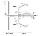
- FIG. 1 is a diagram illustrating a method for manufacturing an optical laminate according to an embodiment of the present invention. It should be noted that FIG. 1 is schematic for ease of viewing, and the scale is not accurately described.
- the optical laminate manufacturing method in this embodiment includes (a) a process of manufacturing the thin glass 10 (hereinafter, also referred to as a thin glass manufacturing process), and (b) laminating the optical films 20 and 20 ′ on the thin glass 10.
- a process hereinafter also referred to as a lamination process.
- a thin glass manufacturing process and a lamination process are performed by an integrated line. More specifically, the thin glass continuously formed in the thin glass production process is used as it is without being wound.
- the thin glass 10 is a mixture of a main raw material such as silica and alumina, an antifoaming agent such as sodium nitrate and antimony oxide, and a reducing agent such as carbon at a temperature of 1400 ° C. to 1600 ° C. It is produced by melting and forming into a thin plate shape and then cooling.
- the method for forming the thin glass 10 include a slot down draw method, a fusion method, and a float method.
- the thin glass formed into a plate shape by these methods may be chemically polished with a solvent such as hydrofluoric acid, if necessary, in order to reduce the thickness or improve the smoothness.
- the line speed in the thin glass production process is preferably 1 m / min or more, more preferably 5 m / min or more, further preferably 10 m / min or more, particularly preferably 15 m / min or more, and most preferably. Is 20 m / min or more.
- the upper limit of the line speed is preferably 100 m / min or less, more preferably 60 m / min or less.
- the line speed in the thin glass manufacturing process and the line speed in the laminating process are the same speed, and the speed is consistent. It is also the line speed of the line.
- the thickness of the thin glass 10 is 100 ⁇ m or less, preferably 80 ⁇ m or less, more preferably 50 ⁇ m or less, still more preferably 40 ⁇ m or less, and particularly preferably 10 ⁇ m to 35 ⁇ m. In the present invention, even if a very thin glass is used, the glass is prevented from being damaged, and an optical laminate can be obtained with high production efficiency.
- the width of the thin glass 10 is preferably 500 mm to 2000 mm, and more preferably 750 mm to 1500 mm.
- the light transmittance of the thin glass 10 at a wavelength of 550 nm is preferably 85% or more.
- the refractive index ng of the thin glass 10 at a wavelength of 550 nm is preferably 1.4 to 1.65.
- the density of the thin glass 10 is preferably 2.3 g / cm 3 to 3.0 g / cm 3 , and more preferably 2.3 g / cm 3 to 2.7 g / cm 3 . If it is the said range, a lightweight optical laminated body will be obtained.
- the thin glass 10 is preferably long.
- the length of the thin glass 10 is, for example, 10 m to 5000 m, and preferably 50 m to 5000 m.
- the thin glass 10 formed with a predetermined thickness and a predetermined width is sent to the next step, the lamination step, by any appropriate conveying method without being wound up in the step.
- conveyance method include roll conveyance and belt conveyance.
- an optical film is laminated on one side or both sides of the thin glass.
- the optical films 20 and 20 ′ are laminated on both surfaces of the thin glass 10 as shown in the illustrated example.
- an optical film is laminated on one surface of a thin glass, and a resin film is laminated on the other surface.
- the resin film mainly has a function as a protective film for protecting the thin glass.
- an optical film is laminated on one surface of a thin glass, and an optical laminate including the thin glass and one optical film is manufactured.
- any appropriate material is used as the material constituting the optical films 20 and 20 '.
- the material constituting the optical films 20 and 20 ' include, for example, polyvinyl alcohol (PVA) resin, polyolefin resin, cyclic olefin resin, polycarbonate resin, cellulose resin, polyester resin, polyvinyl alcohol resin, Polyamide resins, polyimide resins, polyether resins, polystyrene resins, (meth) acrylic resins, (meth) acrylic urethane resins, polysulfone resins, acetate resins, epoxy resins, silicone resins, etc. It is done.
- a metal film, a metal oxide film such as an ITO film, or a laminated film of a metal film and a resin film may be used.
- thermoplastic resin is preferably used as a material constituting the resin film.
- the resin include polyether sulfone resins; polycarbonate resins; acrylic resins; polyester resins such as polyethylene terephthalate resins and polyethylene naphthalate resins; polyolefin resins; cycloolefin resins such as norbornene resins.
- a crosslinkable resin such as an epoxy resin, a urethane resin, or a silicone resin may be used.
- the elastic modulus at 23 ° C. of the optical films 20, 20 ′ and the resin film is preferably 1.5 GPa to 10 GPa, more preferably 1.8 GPa to 9 GPa, and further preferably 1.8 GPa to 8 GPa. If it is such a range, the effect which protects thin glass is high, and the manufacturing method of the optical laminated body excellent in manufacturing efficiency can be provided.
- the elastic modulus in the present invention can be measured by dynamic viscoelastic spectrum measurement.
- the thickness of the optical films 20 and 20 ′ can be set to any appropriate thickness depending on the use of the optical film.
- the thickness of the optical films 20 and 20 ' is, for example, 1 ⁇ m to 300 ⁇ m, preferably 5 ⁇ m to 200 ⁇ m.
- the thickness of the resin films 20 and 20 ' is preferably 1 ⁇ m to 60 ⁇ m, more preferably 10 ⁇ m to 50 ⁇ m, and still more preferably 20 ⁇ m to 40 ⁇ m.
- the widths of the optical films 20, 20 'and the resin film are preferably 300 mm to 2200 mm, more preferably 500 mm to 2000 mm, and further preferably 750 mm to 1500 mm.
- variety of both films may be the same and may differ.
- the optical films 20, 20 'and the resin film are narrower than the thin glass. If the widths of the optical films 20, 20 ′ and the resin film are made narrower than the width of the thin glass, the edge of the thin glass in the width direction can be detected after the laminating step to correct the skew and meander of the thin glass. it can. As a result, the thin glass is prevented from being broken during winding.
- the optical films 20, 20 ′ and the resin film are wider than the thin glass 10. If the widths of the optical films 20 and 20 ′ and the resin film are wider than the width of the thin glass 10, the end of the thin glass 10 is protected and breakage during the process can be prevented.
- the optical films 20, 20 ′ and the resin film are preferably long, and the films can be laminated on the long thin glass 10 continuously.
- the lengths of the optical films 20 and 20 ′ and the resin film may be the same as or different from the length of the thin glass 10.
- the length of both films may be the same and may differ.
- the optical films 20 and 20 ′ are laminated on a thin glass via an adhesive layer 31. More specifically, in the laminating step, after the adhesive film is applied to the optical films 20 and 20 ′ to form the coating layer 30, the thin glass 10 and the optical films 20 and 20 ′ are interposed through the coating layer 30. And then the adhesive is cured.
- the adhesive layer 31 is formed by curing the adhesive (that is, the coating layer 30).
- the line speeds of the thin glass manufacturing process and the laminating process are the same. In general, the line speed of glass production increases as the glass to be produced is thinner.
- the line speed of the entire integrated line is increased, and the line speed of the laminating process is also increased.
- the manufacturing method having such a configuration as described above, after forming the coating layer of the adhesive, the thin glass and the optical film are bonded together, and the adhesive layer is formed by curing the adhesive, thereby bonding. Problems such as defects can be prevented, and the line length can be shortened.
- any appropriate adhesive is used as the adhesive.
- the adhesive include an adhesive including a resin having a cyclic ether group such as an epoxy group, a glycidyl group, and an oxetanyl group, an acrylic resin, a silicone resin, and the like.
- an ultraviolet curable adhesive is used.
- the adhesive applied to both surfaces of the thin glass 10 may be the same or different.
- the above-mentioned adhesive coating methods include air doctor coating, blade coating, knife coating, reverse coating, transfer roll coating, gravure roll coating, kiss coating, cast coating, spray coating, slot orifice coating, calendar coating, and electrodeposition coating.
- Coating methods such as dip coating and die coating; relief printing methods such as flexographic printing; intaglio printing methods such as direct gravure printing methods and offset gravure printing methods; lithographic printing methods such as offset printing methods; stencil printing such as screen printing methods And printing methods such as law.
- the thickness of the adhesive coating layer 30 is preferably 0.001 ⁇ m to 20 ⁇ m, more preferably 0.005 ⁇ m to 20 ⁇ m, still more preferably 0.01 ⁇ m to 10 ⁇ m, and particularly preferably 0.1 ⁇ m. ⁇ 10 ⁇ m.
- the thickness of the coating layer formed on both surfaces of the thin glass 10 may be the same, and may differ.
- the thin glass 10 and the optical films 20 and 20 ′ are pasted at a predetermined interval. Match.
- the adhesive may be semi-cured before the thin glass 10 and the optical films 20 and 20 ′ are bonded together.
- Arbitrary appropriate methods can be employ
- the two optical films 20 and 20 ′ may be laminated at the same timing, or the two optical films 20 and 20 ′ may be laminated at different timings. May be.
- the thin glass 10 and the optical films 20, 20 ′ having the thin glass 10 and the adhesive coating layer 30 formed thereon are run between a pair of rolls. And paste together.
- the thin glass 10 and the optical films 20 and 20 ′ are bonded together. This can prevent the thin glass 10 from being damaged. More specifically, since the roll gap can be widened and the surface hardness of the roll can be set soft, breakage of the thin glass is prevented.
- the gap between the pair of rolls is preferably 50% to 99%, more preferably 60% to 99%, based on the total thickness of the thin glass, the adhesive coating layer, and the optical film.
- total thickness of thin glass and adhesive coating layer and optical film means thin glass and adhesive The total of the coating layer and two optical films.
- the rubber hardness of the roll used for bonding is preferably 10 degrees to 95 degrees, and more preferably 20 degrees to 90 degrees. In one embodiment, the rubber hardness of the roll used for laminating is preferably 95 degrees or less, more preferably 20 degrees to 90 degrees, further preferably 50 degrees to 90 degrees, and particularly preferably. 50 degrees to 80 degrees. The rubber hardness is measured according to JIS K-6253 (A type).
- thin glass is inserted from below into a pair of rolls (that is, the thin glass travels from below to above) in one embodiment. If it does in this way, since the said roll rotates in the direction opposite to the self-weight direction (downward direction) of air, bonding thin glass and an optical film can be performed, suppressing that thin glass entrains air. it can. As a result, it is possible to prevent poor adhesion between the thin glass and the optical film and poor appearance of the optical laminate. In order to prevent air entrapment between the thin glass / optical film, a method of increasing the pressure by the roll or increasing the hardness of the roll to such an extent that the thin glass is not broken may be employed.
- the thin glass is fed into the laminating process while transporting the belt, and between the belt and the roll, the optical film on which the thin glass and the coating layer of the adhesive are formed is run, A thin glass and an optical film are bonded together.
- the thin glass is prevented from being damaged.
- the adhesive coating layer 30 is cured.
- the method of curing the adhesive include a method of curing by ultraviolet light irradiation and / or heat treatment.
- the irradiation condition of the ultraviolet light irradiation is typically such that the cumulative amount of irradiation is 100 mJ / cm 2 to 2000 mJ / cm 2 , preferably 200 mJ / cm 2 to 1000 mJ / cm 2 .
- the adhesive is cured by ultraviolet irradiation.
- the adhesive By curing the adhesive by irradiating with ultraviolet rays, it becomes easy to cope with the thinning of the glass and the increase of the line speed.
- the curing shrinkage rate of the adhesive coating layer is preferably 0.1% to 30%, more preferably 0.5% to 20%.
- the “curing shrinkage rate of the adhesive coating layer” is a volume change rate when the adhesive coating layer is cured to form the adhesive layer, and ⁇ (volume of coating layer ⁇ adhesive layer) / Volume of coating layer ⁇ .
- the cure shrinkage rate can be measured by a cure shrinkage sensor “resin cure shrinkage stress measuring device EU201C” manufactured by Sentec. Details of the method for measuring the curing shrinkage rate are described in JP2013-104869A, which is incorporated herein by reference.
- the adhesive when optical films are laminated on both sides of a thin glass, the adhesive is cured after the optical films are bonded to both sides of the thin glass.
- the adhesive disposed between the thin glass and the first optical film is cured, and then the thin glass After bonding a 2nd optical film on the other surface of this, the adhesive agent arrange
- the adhesive can be cured as described above, and the thin glass and the resin film can be laminated.
- the adhesive layer 31 is formed between the thin glass 10 and the optical films 20 and 20 ', and as a result, an optical laminate is obtained.
- the thickness of the adhesive layer 31 is preferably 0.001 ⁇ m to 20 ⁇ m, and more preferably 0.01 ⁇ m to 10 ⁇ m. If it is such thickness, there will be little influence with respect to the transparency of a transparent substrate, and sufficient adhesive force can be expressed also under a high temperature, high humidity condition.
- both ends of the thin glass in the width direction may be slit at any appropriate timing.
- the thin glass can be prevented from being damaged by slitting and removing both ends in the width direction of the thin glass damaged at both ends in the thin glass manufacturing process.
- the slit is performed before the thin glass and the optical film are bonded (that is, in a state where the thin glass is a single body).
- the slit is performed after laminating the thin glass and the optical film and before the winding process described later.
- the optical laminated body manufactured as described above is subjected to a winding process, and an optical laminated body wound up in a roll shape through the winding process is obtained. finish. Further, after the stacking step, that is, after forming the optical layered body, the optical layered body may be wound after the optical layered body is subjected to any appropriate treatment.
- the optical laminate obtained by the production method of the present invention can be suitably used for a substrate for a display element, a sealing material for an organic EL element, a whole surface protective plate, and the like.
Landscapes
- Chemical & Material Sciences (AREA)
- Engineering & Computer Science (AREA)
- Materials Engineering (AREA)
- Organic Chemistry (AREA)
- Physics & Mathematics (AREA)
- Optics & Photonics (AREA)
- Laminated Bodies (AREA)
- Surface Treatment Of Glass (AREA)
- Electroluminescent Light Sources (AREA)
- Joining Of Glass To Other Materials (AREA)
Abstract
Priority Applications (4)
| Application Number | Priority Date | Filing Date | Title |
|---|---|---|---|
| KR1020187001348A KR20180018760A (ko) | 2015-07-15 | 2016-07-13 | 광학 적층체의 제조 방법 |
| CN201680041564.7A CN107848252B (zh) | 2015-07-15 | 2016-07-13 | 光学积层体的制造方法 |
| EP16824477.0A EP3323608B1 (fr) | 2015-07-15 | 2016-07-13 | Procédé de production pour stratifié optique |
| US15/743,414 US20180207906A1 (en) | 2015-07-15 | 2016-07-13 | Production method for optical laminate |
Applications Claiming Priority (2)
| Application Number | Priority Date | Filing Date | Title |
|---|---|---|---|
| JP2015-141265 | 2015-07-15 | ||
| JP2015141265A JP6614833B2 (ja) | 2015-07-15 | 2015-07-15 | 光学積層体の製造方法 |
Publications (1)
| Publication Number | Publication Date |
|---|---|
| WO2017010497A1 true WO2017010497A1 (fr) | 2017-01-19 |
Family
ID=57757500
Family Applications (1)
| Application Number | Title | Priority Date | Filing Date |
|---|---|---|---|
| PCT/JP2016/070638 Ceased WO2017010497A1 (fr) | 2015-07-15 | 2016-07-13 | Procédé de production pour stratifié optique |
Country Status (7)
| Country | Link |
|---|---|
| US (1) | US20180207906A1 (fr) |
| EP (1) | EP3323608B1 (fr) |
| JP (1) | JP6614833B2 (fr) |
| KR (1) | KR20180018760A (fr) |
| CN (1) | CN107848252B (fr) |
| TW (1) | TWI698657B (fr) |
| WO (1) | WO2017010497A1 (fr) |
Families Citing this family (2)
| Publication number | Priority date | Publication date | Assignee | Title |
|---|---|---|---|---|
| CN113853300A (zh) * | 2019-06-27 | 2021-12-28 | 日东电工株式会社 | 层叠膜的制造方法 |
| CN118927760A (zh) * | 2024-08-26 | 2024-11-12 | 伯恩光学(惠州)有限公司 | 一种超薄玻璃点胶贴合固化方法 |
Citations (5)
| Publication number | Priority date | Publication date | Assignee | Title |
|---|---|---|---|---|
| JP2001097733A (ja) * | 1999-09-29 | 2001-04-10 | Mitsubishi Plastics Ind Ltd | ガラスフィルムの取扱い方法及びガラス積層体 |
| JP2013014441A (ja) * | 2011-06-30 | 2013-01-24 | Nippon Electric Glass Co Ltd | ガラスロールの製造方法 |
| WO2013114979A1 (fr) * | 2012-01-30 | 2013-08-08 | コニカミノルタアドバンストレイヤー株式会社 | Plaque polarisante, procédé de fabrication d'une plaque polarisante et dispositif d'affichage à cristaux liquides |
| JP2014215592A (ja) * | 2013-04-30 | 2014-11-17 | コニカミノルタ株式会社 | 偏光機能付きガラスおよびそれを備えた液晶表示装置 |
| JP2015007764A (ja) * | 2013-05-27 | 2015-01-15 | 富士フイルム株式会社 | 光学フィルム、組成物、平面画像表示装置、立体画像表示装置、液晶表示装置、有機el表示装置、光学フィルムの製造方法 |
Family Cites Families (14)
| Publication number | Priority date | Publication date | Assignee | Title |
|---|---|---|---|---|
| EP1048628A1 (fr) * | 1999-04-30 | 2000-11-02 | Schott Glas | Substrat de folie en verre revêtu avec une couche polymerisée |
| US20040069770A1 (en) * | 2002-10-11 | 2004-04-15 | Schott Corporation | Glass/metal laminate for appliances |
| DE602006019317D1 (de) * | 2005-11-29 | 2011-02-10 | Seiko Instr Inc | Prozess zur display-herstellung und laminationsverfahren |
| EP2204355A4 (fr) * | 2007-10-30 | 2012-10-31 | Asahi Glass Co Ltd | Procédés de fabrication de composite de verre/résine |
| JP4691205B1 (ja) * | 2010-09-03 | 2011-06-01 | 日東電工株式会社 | 薄型高機能偏光膜を含む光学フィルム積層体の製造方法 |
| KR101362881B1 (ko) * | 2010-12-31 | 2014-02-14 | 제일모직주식회사 | 디스플레이용 광학 점착제 조성물 |
| CN103347665B (zh) * | 2011-02-10 | 2015-06-17 | 埃西勒国际通用光学公司 | 用一种热塑性膜来防护破裂和龟裂的对有机玻璃钻孔的方法 |
| TWI547369B (zh) * | 2011-05-27 | 2016-09-01 | 康寧公司 | 玻璃塑膠積層之裝置、處理線、及方法 |
| US20130196163A1 (en) * | 2012-01-31 | 2013-08-01 | 3M Innovative Properties Company | Composite glass laminate and web processing apparatus |
| JP5781464B2 (ja) * | 2012-03-30 | 2015-09-24 | 富士フイルム株式会社 | 塗膜付きフィルムの製造方法 |
| JP5883333B2 (ja) * | 2012-04-02 | 2016-03-15 | 日東電工株式会社 | 透明シートおよびその製造方法 |
| KR101949561B1 (ko) * | 2012-10-12 | 2019-02-18 | 코닝 인코포레이티드 | 잔류 강도를 갖는 제품 |
| TWI631019B (zh) * | 2013-04-19 | 2018-08-01 | 美商康寧公司 | 形成積層玻璃結構之方法 |
| JP2015147916A (ja) * | 2014-02-10 | 2015-08-20 | 日本化薬株式会社 | タッチパネル用紫外線硬化型接着剤組成物、それを用いた貼り合せ方法及び物品 |
-
2015
- 2015-07-15 JP JP2015141265A patent/JP6614833B2/ja active Active
-
2016
- 2016-07-13 KR KR1020187001348A patent/KR20180018760A/ko not_active Ceased
- 2016-07-13 US US15/743,414 patent/US20180207906A1/en not_active Abandoned
- 2016-07-13 CN CN201680041564.7A patent/CN107848252B/zh active Active
- 2016-07-13 EP EP16824477.0A patent/EP3323608B1/fr active Active
- 2016-07-13 WO PCT/JP2016/070638 patent/WO2017010497A1/fr not_active Ceased
- 2016-07-15 TW TW105122464A patent/TWI698657B/zh active
Patent Citations (5)
| Publication number | Priority date | Publication date | Assignee | Title |
|---|---|---|---|---|
| JP2001097733A (ja) * | 1999-09-29 | 2001-04-10 | Mitsubishi Plastics Ind Ltd | ガラスフィルムの取扱い方法及びガラス積層体 |
| JP2013014441A (ja) * | 2011-06-30 | 2013-01-24 | Nippon Electric Glass Co Ltd | ガラスロールの製造方法 |
| WO2013114979A1 (fr) * | 2012-01-30 | 2013-08-08 | コニカミノルタアドバンストレイヤー株式会社 | Plaque polarisante, procédé de fabrication d'une plaque polarisante et dispositif d'affichage à cristaux liquides |
| JP2014215592A (ja) * | 2013-04-30 | 2014-11-17 | コニカミノルタ株式会社 | 偏光機能付きガラスおよびそれを備えた液晶表示装置 |
| JP2015007764A (ja) * | 2013-05-27 | 2015-01-15 | 富士フイルム株式会社 | 光学フィルム、組成物、平面画像表示装置、立体画像表示装置、液晶表示装置、有機el表示装置、光学フィルムの製造方法 |
Also Published As
| Publication number | Publication date |
|---|---|
| TW201730587A (zh) | 2017-09-01 |
| JP2017019255A (ja) | 2017-01-26 |
| JP6614833B2 (ja) | 2019-12-04 |
| EP3323608A4 (fr) | 2019-03-20 |
| EP3323608A1 (fr) | 2018-05-23 |
| US20180207906A1 (en) | 2018-07-26 |
| TWI698657B (zh) | 2020-07-11 |
| CN107848252B (zh) | 2020-11-24 |
| EP3323608B1 (fr) | 2024-02-14 |
| KR20180018760A (ko) | 2018-02-21 |
| CN107848252A (zh) | 2018-03-27 |
Similar Documents
| Publication | Publication Date | Title |
|---|---|---|
| TWI840323B (zh) | 玻璃薄膜-樹脂複合物 | |
| JP6614833B2 (ja) | 光学積層体の製造方法 | |
| JP6614834B2 (ja) | 光学積層体の製造方法 | |
| JP7402860B2 (ja) | 積層フィルムの製造方法 | |
| WO2019208360A1 (fr) | Composite film de verre-résine | |
| TWI820120B (zh) | 玻璃薄膜-樹脂複合體 | |
| JP7410948B2 (ja) | 積層フィルムの製造方法 | |
| WO2018079441A1 (fr) | Procédé de production de stratifié de films | |
| KR102842335B1 (ko) | 폴더블 스마트폰용 보호필름 제조방법 | |
| KR20240042367A (ko) | 장척 적층체 |
Legal Events
| Date | Code | Title | Description |
|---|---|---|---|
| 121 | Ep: the epo has been informed by wipo that ep was designated in this application |
Ref document number: 16824477 Country of ref document: EP Kind code of ref document: A1 |
|
| WWE | Wipo information: entry into national phase |
Ref document number: 15743414 Country of ref document: US |
|
| ENP | Entry into the national phase |
Ref document number: 20187001348 Country of ref document: KR Kind code of ref document: A |
|
| NENP | Non-entry into the national phase |
Ref country code: DE |
|
| WWE | Wipo information: entry into national phase |
Ref document number: 2016824477 Country of ref document: EP |