WO2017013699A1 - 内燃機関用電源装置 - Google Patents
内燃機関用電源装置 Download PDFInfo
- Publication number
- WO2017013699A1 WO2017013699A1 PCT/JP2015/070494 JP2015070494W WO2017013699A1 WO 2017013699 A1 WO2017013699 A1 WO 2017013699A1 JP 2015070494 W JP2015070494 W JP 2015070494W WO 2017013699 A1 WO2017013699 A1 WO 2017013699A1
- Authority
- WO
- WIPO (PCT)
- Prior art keywords
- power generation
- generation coil
- voltage
- load
- coil
- Prior art date
- Legal status (The legal status is an assumption and is not a legal conclusion. Google has not performed a legal analysis and makes no representation as to the accuracy of the status listed.)
- Ceased
Links
Images




Classifications
-
- H—ELECTRICITY
- H02—GENERATION; CONVERSION OR DISTRIBUTION OF ELECTRIC POWER
- H02P—CONTROL OR REGULATION OF ELECTRIC MOTORS, ELECTRIC GENERATORS OR DYNAMO-ELECTRIC CONVERTERS; CONTROLLING TRANSFORMERS, REACTORS OR CHOKE COILS
- H02P9/00—Arrangements for controlling electric generators for the purpose of obtaining a desired output
- H02P9/14—Arrangements for controlling electric generators for the purpose of obtaining a desired output by variation of field
- H02P9/26—Arrangements for controlling electric generators for the purpose of obtaining a desired output by variation of field using discharge tubes or semiconductor devices
- H02P9/30—Arrangements for controlling electric generators for the purpose of obtaining a desired output by variation of field using discharge tubes or semiconductor devices using semiconductor devices
- H02P9/305—Arrangements for controlling electric generators for the purpose of obtaining a desired output by variation of field using discharge tubes or semiconductor devices using semiconductor devices controlling voltage
-
- H—ELECTRICITY
- H02—GENERATION; CONVERSION OR DISTRIBUTION OF ELECTRIC POWER
- H02K—DYNAMO-ELECTRIC MACHINES
- H02K21/00—Synchronous motors having permanent magnets; Synchronous generators having permanent magnets
- H02K21/02—Details
- H02K21/04—Windings on magnets for additional excitation ; Windings and magnets for additional excitation
-
- H—ELECTRICITY
- H02—GENERATION; CONVERSION OR DISTRIBUTION OF ELECTRIC POWER
- H02K—DYNAMO-ELECTRIC MACHINES
- H02K21/00—Synchronous motors having permanent magnets; Synchronous generators having permanent magnets
- H02K21/02—Details
- H02K21/04—Windings on magnets for additional excitation ; Windings and magnets for additional excitation
- H02K21/046—Windings on magnets for additional excitation ; Windings and magnets for additional excitation with rotating permanent magnets and stationary field winding
-
- H—ELECTRICITY
- H02—GENERATION; CONVERSION OR DISTRIBUTION OF ELECTRIC POWER
- H02M—APPARATUS FOR CONVERSION BETWEEN AC AND AC, BETWEEN AC AND DC, OR BETWEEN DC AND DC, AND FOR USE WITH MAINS OR SIMILAR POWER SUPPLY SYSTEMS; CONVERSION OF DC OR AC INPUT POWER INTO SURGE OUTPUT POWER; CONTROL OR REGULATION THEREOF
- H02M7/00—Conversion of AC power input into DC power output; Conversion of DC power input into AC power output
- H02M7/02—Conversion of AC power input into DC power output without possibility of reversal
- H02M7/04—Conversion of AC power input into DC power output without possibility of reversal by static converters
- H02M7/12—Conversion of AC power input into DC power output without possibility of reversal by static converters using discharge tubes with control electrode or semiconductor devices with control electrode
- H02M7/145—Conversion of AC power input into DC power output without possibility of reversal by static converters using discharge tubes with control electrode or semiconductor devices with control electrode using devices of a thyratron or thyristor type requiring extinguishing means
- H02M7/155—Conversion of AC power input into DC power output without possibility of reversal by static converters using discharge tubes with control electrode or semiconductor devices with control electrode using devices of a thyratron or thyristor type requiring extinguishing means using semiconductor devices only
-
- H—ELECTRICITY
- H02—GENERATION; CONVERSION OR DISTRIBUTION OF ELECTRIC POWER
- H02M—APPARATUS FOR CONVERSION BETWEEN AC AND AC, BETWEEN AC AND DC, OR BETWEEN DC AND DC, AND FOR USE WITH MAINS OR SIMILAR POWER SUPPLY SYSTEMS; CONVERSION OF DC OR AC INPUT POWER INTO SURGE OUTPUT POWER; CONTROL OR REGULATION THEREOF
- H02M7/00—Conversion of AC power input into DC power output; Conversion of DC power input into AC power output
- H02M7/02—Conversion of AC power input into DC power output without possibility of reversal
- H02M7/04—Conversion of AC power input into DC power output without possibility of reversal by static converters
- H02M7/12—Conversion of AC power input into DC power output without possibility of reversal by static converters using discharge tubes with control electrode or semiconductor devices with control electrode
- H02M7/145—Conversion of AC power input into DC power output without possibility of reversal by static converters using discharge tubes with control electrode or semiconductor devices with control electrode using devices of a thyratron or thyristor type requiring extinguishing means
- H02M7/155—Conversion of AC power input into DC power output without possibility of reversal by static converters using discharge tubes with control electrode or semiconductor devices with control electrode using devices of a thyratron or thyristor type requiring extinguishing means using semiconductor devices only
- H02M7/1555—Conversion of AC power input into DC power output without possibility of reversal by static converters using discharge tubes with control electrode or semiconductor devices with control electrode using devices of a thyratron or thyristor type requiring extinguishing means using semiconductor devices only with control circuit
- H02M7/1557—Conversion of AC power input into DC power output without possibility of reversal by static converters using discharge tubes with control electrode or semiconductor devices with control electrode using devices of a thyratron or thyristor type requiring extinguishing means using semiconductor devices only with control circuit with automatic control of the output voltage or current
-
- H—ELECTRICITY
- H02—GENERATION; CONVERSION OR DISTRIBUTION OF ELECTRIC POWER
- H02P—CONTROL OR REGULATION OF ELECTRIC MOTORS, ELECTRIC GENERATORS OR DYNAMO-ELECTRIC CONVERTERS; CONTROLLING TRANSFORMERS, REACTORS OR CHOKE COILS
- H02P1/00—Arrangements for starting electric motors or dynamo-electric converters
- H02P1/02—Details of starting control
-
- H—ELECTRICITY
- H02—GENERATION; CONVERSION OR DISTRIBUTION OF ELECTRIC POWER
- H02P—CONTROL OR REGULATION OF ELECTRIC MOTORS, ELECTRIC GENERATORS OR DYNAMO-ELECTRIC CONVERTERS; CONTROLLING TRANSFORMERS, REACTORS OR CHOKE COILS
- H02P1/00—Arrangements for starting electric motors or dynamo-electric converters
- H02P1/16—Arrangements for starting electric motors or dynamo-electric converters for starting dynamo-electric motors or dynamo-electric converters
-
- H—ELECTRICITY
- H02—GENERATION; CONVERSION OR DISTRIBUTION OF ELECTRIC POWER
- H02P—CONTROL OR REGULATION OF ELECTRIC MOTORS, ELECTRIC GENERATORS OR DYNAMO-ELECTRIC CONVERTERS; CONTROLLING TRANSFORMERS, REACTORS OR CHOKE COILS
- H02P11/00—Arrangements for controlling dynamo-electric converters
- H02P11/04—Arrangements for controlling dynamo-electric converters for controlling dynamo-electric converters having a DC output
-
- H—ELECTRICITY
- H02—GENERATION; CONVERSION OR DISTRIBUTION OF ELECTRIC POWER
- H02P—CONTROL OR REGULATION OF ELECTRIC MOTORS, ELECTRIC GENERATORS OR DYNAMO-ELECTRIC CONVERTERS; CONTROLLING TRANSFORMERS, REACTORS OR CHOKE COILS
- H02P9/00—Arrangements for controlling electric generators for the purpose of obtaining a desired output
- H02P9/04—Control effected upon non-electric prime mover and dependent upon electric output value of the generator
-
- H—ELECTRICITY
- H02—GENERATION; CONVERSION OR DISTRIBUTION OF ELECTRIC POWER
- H02P—CONTROL OR REGULATION OF ELECTRIC MOTORS, ELECTRIC GENERATORS OR DYNAMO-ELECTRIC CONVERTERS; CONTROLLING TRANSFORMERS, REACTORS OR CHOKE COILS
- H02P9/00—Arrangements for controlling electric generators for the purpose of obtaining a desired output
- H02P9/08—Control of generator circuit during starting or stopping of driving means, e.g. for initiating excitation
-
- H—ELECTRICITY
- H02—GENERATION; CONVERSION OR DISTRIBUTION OF ELECTRIC POWER
- H02P—CONTROL OR REGULATION OF ELECTRIC MOTORS, ELECTRIC GENERATORS OR DYNAMO-ELECTRIC CONVERTERS; CONTROLLING TRANSFORMERS, REACTORS OR CHOKE COILS
- H02P9/00—Arrangements for controlling electric generators for the purpose of obtaining a desired output
- H02P9/10—Control effected upon generator excitation circuit to reduce harmful effects of overloads or transients, e.g. sudden application of load, sudden removal of load, sudden change of load
-
- H—ELECTRICITY
- H02—GENERATION; CONVERSION OR DISTRIBUTION OF ELECTRIC POWER
- H02P—CONTROL OR REGULATION OF ELECTRIC MOTORS, ELECTRIC GENERATORS OR DYNAMO-ELECTRIC CONVERTERS; CONTROLLING TRANSFORMERS, REACTORS OR CHOKE COILS
- H02P9/00—Arrangements for controlling electric generators for the purpose of obtaining a desired output
- H02P9/10—Control effected upon generator excitation circuit to reduce harmful effects of overloads or transients, e.g. sudden application of load, sudden removal of load, sudden change of load
- H02P9/107—Control effected upon generator excitation circuit to reduce harmful effects of overloads or transients, e.g. sudden application of load, sudden removal of load, sudden change of load for limiting effects of overloads
-
- H—ELECTRICITY
- H02—GENERATION; CONVERSION OR DISTRIBUTION OF ELECTRIC POWER
- H02P—CONTROL OR REGULATION OF ELECTRIC MOTORS, ELECTRIC GENERATORS OR DYNAMO-ELECTRIC CONVERTERS; CONTROLLING TRANSFORMERS, REACTORS OR CHOKE COILS
- H02P9/00—Arrangements for controlling electric generators for the purpose of obtaining a desired output
- H02P9/14—Arrangements for controlling electric generators for the purpose of obtaining a desired output by variation of field
- H02P9/26—Arrangements for controlling electric generators for the purpose of obtaining a desired output by variation of field using discharge tubes or semiconductor devices
- H02P9/30—Arrangements for controlling electric generators for the purpose of obtaining a desired output by variation of field using discharge tubes or semiconductor devices using semiconductor devices
-
- H—ELECTRICITY
- H02—GENERATION; CONVERSION OR DISTRIBUTION OF ELECTRIC POWER
- H02P—CONTROL OR REGULATION OF ELECTRIC MOTORS, ELECTRIC GENERATORS OR DYNAMO-ELECTRIC CONVERTERS; CONTROLLING TRANSFORMERS, REACTORS OR CHOKE COILS
- H02P9/00—Arrangements for controlling electric generators for the purpose of obtaining a desired output
- H02P9/48—Arrangements for obtaining a constant output value at varying speed of the generator, e.g. on vehicle
-
- H—ELECTRICITY
- H02—GENERATION; CONVERSION OR DISTRIBUTION OF ELECTRIC POWER
- H02P—CONTROL OR REGULATION OF ELECTRIC MOTORS, ELECTRIC GENERATORS OR DYNAMO-ELECTRIC CONVERTERS; CONTROLLING TRANSFORMERS, REACTORS OR CHOKE COILS
- H02P2201/00—Indexing scheme relating to controlling arrangements characterised by the converter used
- H02P2201/03—AC-DC converter stage controlled to provide a defined DC link voltage
Definitions
- the present invention relates to a power supply apparatus that supplies electric power to various electrical components using a generator driven by an internal combustion engine as a power source.
- the generator attached to the internal combustion engine includes a magnet rotor having a magnetic field formed by permanent magnets, and a stator formed by winding a power generation coil around an armature core having a magnetic pole portion facing the magnetic pole of the magnet rotor.
- Many magnet generators are provided. While the magnet generator is an AC generator, most of the electrical components provided in the equipment equipped with the internal combustion engine are DC loads, so that this type of generator is used as a power source to supply power to various electrical components.
- a circuit for converting the output voltage of the generator into a DC voltage is required.
- a battery When a battery is not installed in equipment equipped with an internal combustion engine, it is always driven to operate the engine, such as a fuel pump of a fuel injection device that supplies fuel to the internal combustion engine or an ignition device that ignites the internal combustion engine. It is necessary to drive an electrical component load that is required to be performed by a power supply device that uses a generator driven by an internal combustion engine as a power source. In such a case, in order to improve the startability of the engine, the voltage generated by the generator during the extremely low speed rotation of the engine is increased so that the rotation speed at which the supply of power from the power source to the load is started as much as possible. Not only is it required to be low, but it is also necessary to generate sufficient voltage necessary to drive the load even at high engine speeds.
- a power supply device using a generator driven by the engine as a power source is used to charge the battery.
- a power supply device for an internal combustion engine There is a need to generate a large output voltage at low engine speed without sacrificing the output voltage at high engine speed.
- Patent Document 1 chopper control for intermittently passing a current flowing through a specific power generation coil provided in the generator (an operation of passing a short-circuit current or a current close to a short-circuit current to the power generation coil and this current)
- a power supply device has been proposed in which a boosted voltage is induced in a power generation coil by performing a control for repeatedly performing the shut-off operation) during low-speed rotation of the engine.
- a mixed bridge circuit in which the upper side of the bridge is configured by a diode and the lower side is configured by a MOSFET is used.
- Chopper control is performed by intermittently turning on and off the MOSFETs on both lower sides of the bridge during low-speed rotation, thereby inducing a boosted voltage in the generator coil.
- the voltage is rectified by a rectifier circuit including a diode and a diode on the upper side of the bridge and converted to a DC voltage.
- the voltage induced in a power generation coil at the time of the low speed of an engine can be made high, and the rotational speed at which the drive of a load is started can be made low. Further, since the output of the power generation coil can be increased during low-speed rotation without increasing the number of turns of the power generation coil, it is possible to prevent the voltage generated by the power generation coil from decreasing during high-speed rotation of the engine.
- An object of the present invention is for an internal combustion engine that obtains a boosted DC voltage by rectifying a voltage induced in a power generation coil by intermittently passing a current flowing through a power generation coil provided in a generator driven by the engine.
- An object of the present invention is to make it possible to further increase the DC voltage obtained during low-speed rotation in the power supply device.
- the first invention is an armature core having n teeth (n is an integer of 2 or more) arranged radially, and m pieces (m is an integer of 2 to n) provided in the armature core. And a magnetic field provided with a plurality of magnetic poles opposed to the magnetic pole part formed at the tip of each tooth part of the armature core.
- a power supply device for an internal combustion engine including an AC generator having a rotor that is driven to rotate by the internal combustion engine and an AC / DC conversion circuit that converts an output voltage of the AC generator into a DC voltage is an object.
- m unit coils wound around m tooth portions (m is an integer of 2 or more and n or less) is a configuration in which unit coils are wound around all n tooth portions. This is intended to include both the case of taking and the case of taking a configuration in which some of the n teeth are allowed to play without being wound by a unit coil.
- the m unit coils are connected so as to constitute at least a first power generation coil and a second power generation coil.
- the first power generating coil is formed by connecting a plurality of unit coils wound respectively around a plurality of teeth arranged every other tooth among m teeth provided on the armature core.
- the second power generation coil has a positional relationship adjacent to the tooth portion around which any of the plurality of unit coils constituting the first power generation coil is wound out of the m tooth portions. It is configured by connecting a plurality of unit coils wound around every other tooth part.
- the AC / DC converter circuit used in the present invention rectifies the voltage induced in the first power generating coil and the first switch means for intermittently passing the current flowing through the first power generating coil when the on / off control is performed.
- a first voltage converting circuit having a first rectifying circuit for converting to a DC voltage supplied to the second voltage, a second switch means for intermittently passing a current flowing through the second power generation coil when on / off controlled, and a second
- a second voltage converter circuit having a second rectifier circuit that rectifies the voltage induced in the power generation coil and converts the voltage into a DC voltage supplied to the second load; and from the second voltage converter circuit to the second load And an energization control switch for controlling the energization of the.
- the energization control switch is turned off to keep the energization from the second voltage conversion circuit to the second load, or from the second voltage conversion circuit to the second load.
- a switch controller for performing is provided.
- the current flowing through the first power generation coil and the second power generation coil in a state where the current flowing from the second voltage conversion circuit to the second load is restricted by turning on and off the energization control switch with a duty ratio of less than 1.
- the energy released from the second power generating coil when the current flowing through the second power generating coil is interrupted is closely packed in the second power generating coil.
- Magnetically coupled second When the current flowing through the first power generation coil is cut off and the energy released from the first power generation coil can be superimposed on the first power generation coil, it is induced in the first power generation coil.
- the voltage can be made higher than the voltage induced when only the current flowing through the first power generation coil is cut off.
- the second invention is also directed to an internal combustion engine power supply device similar to the first invention.
- each unit coil constituting the first power generation coil is replaced with the second power generation coil.
- the unit coil is provided so as to be paired with any of the constituting unit coils, and the unit coil forming each pair of the first power generation coil and the second power generation coil is wound around the same tooth portion of the armature core. ing.
- Other configurations are the same as those of the first invention.
- the first power generation coil and the second power generation coil can be closely magnetically coupled. Therefore, when the current flowing through the second power generation coil is interrupted, the second power generation coil is cut off.
- a voltage induced in the first power generation coil by superimposing the energy released from the first power generation coil on the energy discharged from the first power generation coil when the current flowing through the first power generation coil is interrupted Can be made higher than the voltage induced when only the current flowing through the first power generation coil is cut off.
- the third invention is applied to the first invention and the second invention.
- the first load is an electrical component that is essential to be driven to operate the internal combustion engine.
- the second load is a load that is allowed to stop driving in the process of starting the internal combustion engine, such as a ramp load.
- the rotational speed of the rotor increases to the first set speed set lower than the idling rotational speed of the internal combustion engine, and the second rotational speed of the rotor is higher than the first set speed.
- the number of turns of the first power generation coil and the second power generation coil is set so that the output of the load current is started from the first voltage conversion circuit and the second voltage conversion circuit, respectively, when the speed increases to the set speed. .
- the electrical component that is essential to drive the internal combustion engine is driven by the generator driven by the engine, and the system driven by the internal combustion engine has a battery-less configuration.
- the rotational speed at which the driving of the electrical component is started can be lowered, the startability of the engine can be improved.
- the fourth invention is applied to the third invention.
- the switch control unit controls the on / off control of the first switch means and the second switch means until the start of the internal combustion engine is completed.
- the on / off control is performed at the same time.
- the fifth invention is applied to the fourth invention.
- the switch control unit performs the on / off control of the first switch means and the on / off control of the second switch means in synchronization. Configured to let
- the first voltage conversion circuit includes a first bridge circuit in which one and the other of the upper arm and the lower arm of each leg are each configured by a diode and a MOSFET, and the first bridge circuit
- the first switch means is constituted by the MOSFET constituting the other arm of the first, the diode constituting one arm of the first bridge circuit and the drain source of the MOSFET constituting the other arm of the first bridge circuit.
- a first rectifier circuit is configured by the parasitic diode formed therebetween.
- the second voltage conversion circuit includes a second bridge circuit in which one and the other of the upper arm and the lower arm of each leg are respectively configured by a diode and a MOSFET, and the other arm of the second bridge circuit.
- the second switch means is constituted by the MOSFET constituting the circuit, and is formed between the diode constituting one arm of the second bridge circuit and the drain source of the MOSFET constituting the other arm of the second bridge circuit.
- a second rectifier circuit is configured by the parasitic diode.
- the seventh invention is applied to any one of the third to sixth inventions, and in the present invention, for energization control between the second rectifier circuit and the load of the second rectifier circuit.
- a switch is inserted.
- the switch control unit keeps the energization control switch off until the start of the internal combustion engine is completed, and allows the energization control switch to be turned on after the start of the internal combustion engine is completed. Control the energization control switch.
- the eighth invention is applied to any one of the third to fifth inventions.
- the first voltage conversion circuit, the second voltage conversion circuit, and the switch control unit are as follows. Configured as follows.
- the first voltage conversion circuit includes a first bridge circuit in which one and the other of the upper arm and the lower arm of each leg are respectively configured by a diode and a MOSFET, and the other arm of the first bridge circuit is A parasitic diode formed between a diode constituting one arm of the first bridge circuit and a drain source of the MOSFET constituting the other arm of the first bridge circuit, the first switch means being constituted by the MOSFET constituting Thus, a first rectifier circuit is configured.
- the second voltage conversion circuit includes a second bridge circuit in which one and the other of the upper arm and the lower arm of each leg are respectively constituted by a thyristor and a MOSFET, and the other arm of the second bridge circuit.
- the second switch means is constituted by the MOSFET that constitutes the parasitic element, and is formed between the thyristor that constitutes one arm of the second bridge circuit and the drain source of the MOSFET that constitutes the other arm of the second bridge circuit.
- the diode forms a second rectifier circuit.
- the switch control unit stops supplying the trigger signal to each thyristor of the second voltage conversion circuit until the start of the internal combustion engine is completed, and after the start of the internal combustion engine is completed, the second voltage conversion circuit A trigger signal is supplied to each thyristor.
- the ninth invention is directed to a power supply device similar to the power supply device for an internal combustion engine that is the subject of the first invention.
- control for intermittently passing the current flowing through the second power generation coil is performed. Only the induced voltage of the first power generation coil is boosted.
- the second power generation coil has more turns than the first power generation coil.
- each unit coil constituting the first power generation coil is adjacent to a tooth portion around which one of the unit coils constituting the second power generation coil is wound. It is wound around the teeth.
- the AC / DC converter circuit rectifies the voltage induced in the first power generation coil in order to boost the voltage induced in the first power generation coil simply by controlling the current flowing through the second power generation coil intermittently.
- a first voltage conversion circuit that converts the DC voltage to be supplied to the first load, second switch means for intermittently passing a current flowing through the second power generation coil when on / off controlled, and the second
- a second voltage converter circuit having a second rectifier circuit that rectifies a voltage induced in the power generation coil and converts the voltage into a DC voltage supplied to the second load; and the second voltage converter circuit and the second load And a switch for energization control inserted between the two.
- the switch control unit keeps the energization control switch in the off state, or turns on the energization control switch so as to limit the current flowing from the second power generation coil to the second load.
- the second switch means is configured to perform on / off control so as to boost the voltage supplied to the load.
- the second power generation coil has an inductance larger than the inductance of the first power generation coil.
- the first power generating coil having a small inductance and the second power generating coil having a large inductance are magnetically coupled to each other and the current flowing through the second power generating coil having the larger inductance is intermittently connected, Since the large energy released when the current flowing through the power generating coil is interrupted can be transferred to the first power generating coil, the current flowing through the first power generating coil with the smaller inductance is not interrupted.
- the voltage induced in the first power generation coil can be made higher than when the current flowing in the first power generation coil is intermittent.
- the circuit configuration of the power supply apparatus is complicated. Therefore, the voltage applied to the load driven by the output of the first power generation coil can be increased.
- each unit coil constituting the first power generation coil is provided so as to be paired with any unit coil constituting the second power generation coil.
- the unit coil has a configuration similar to that of the ninth invention except that the unit coil forming each pair of the coil and the second power generating coil is wound around the same tooth portion of the armature core.
- the eleventh aspect of the invention is applied to any one of the first to tenth aspects of the invention.
- m pieces of winding wound around m tooth portions of the armature core of the AC generator are respectively provided.
- the unit coil further includes a unit coil that constitutes another power generation coil. That is, in the present invention, it is allowed that a generator coil is further provided in addition to the first and second generator coils in the stator of the generator.
- the twelfth invention is applied to any one of the first invention to the tenth invention, and in the present invention, m wound around m tooth portions of the armature core of the AC generator.
- a control power source that includes a unit coil that constitutes a third power generating coil having a number of turns that is greater than the number of turns of the first power generating coil, and that converts the output of the third power generating coil into a constant DC voltage.
- a circuit is provided.
- the switch control unit is configured to operate by obtaining a power supply voltage from the control power supply circuit.
- the output voltage of the control power supply circuit is established at a rotational speed lower than the rotational speed at which the first power generation coil starts driving the load, and the switch control unit is made operable. Therefore, the voltage for driving the load can be generated by functioning the switch control unit without using a battery, and the power supply device according to the present invention can be applied to a battery-less system.
- the first power generating coil and the second power generating coil provided in the stator are magnetically tightly coupled, and the second power generating coil. Since the current flowing through both coils is interrupted at the same time in the state where the current from the load to the load is cut off or restricted, the current flowing through the second power generation coil is released from the second power generation coil. The generated energy is transferred to the first power generation coil, and the voltage induced in the first power generation coil is increased to a voltage higher than that in the case where control is performed to interrupt only the current flowing through the first power generation coil. The voltage can be boosted.
- the load induced by the output of the first power generation coil is further increased than before by increasing the voltage induced in the first power generation coil in the region where the rotational speed of the engine is low. It can be activated at a low rotational speed.
- the number of turns of the second power generation coil is made larger than that of the first power generation coil so that the second power generation coil has a larger inductance than that of the first power generation coil.
- the first power generation coil and the second power generation coil are magnetically tightly coupled so that the current flowing through the second power generation coil having the larger inductance is interrupted. Since the voltage induced in the coil is boosted, the induced voltage in the first power generating coil can be boosted to a voltage higher than the conventional one without performing control to interrupt the energization current of the first power generating coil.
- the voltage applied to the load driven by the output of the first power generation coil can be increased without complicating the circuit configuration of the power supply device.
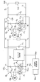
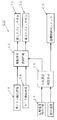
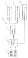
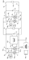
- FIG. 1 is a circuit diagram showing a circuit configuration of an embodiment of a power supply device for an internal combustion engine according to the present invention. It is the block diagram which showed one structural example of the control part used by embodiment of FIG. It is the block diagram which showed the other structural example of the control part used by embodiment of FIG. It is a circuit diagram which shows the circuit structure of other embodiment of the power supply device for internal combustion engines which concerns on this invention. It is a circuit diagram which shows the circuit structure of further another embodiment of the power supply device for internal combustion engines which concerns on this invention. It is the front view which showed roughly the example of 1 structure of the generator used by embodiment of this invention. It is the front view which showed schematically the other structural example of the generator used by embodiment of this invention.
- (A)-(E) are the waveform diagrams for demonstrating operation
- the power supply device according to the present invention when neither the current flowing through the first power generation coil nor the current flowing through the second power generation coil is chopper controlled, only the current flowing through the first power generation coil is chopper controlled.
- the present invention will be described by taking as an example the case where the present invention is applied to a power supply device for an internal combustion engine used in a so-called battery-less device in which an internal combustion engine is mounted. A form is demonstrated.
- the load supplied by the generator attached to the internal combustion engine is constantly driven to operate the engine, such as an ignition device that ignites the internal combustion engine and a fuel pump that supplies fuel to the engine.
- a load that needs to be driven (must be driven), a load that includes a control device such as an ECU (electronic control unit) that controls an ignition device or a fuel pump that needs to be driven at all times, and a driver
- loads such as lamps that are driven according to the conditions.
- a load that needs to be constantly driven to operate the engine such as an ignition device or a fuel pump, is referred to as “always driven load” or “first load”.
- a load that is driven as necessary after the driver starts the engine is referred to as an “anytime drive load” or a “second load”.
- a load such as a control device that controls the constantly driven load is referred to as a “control system load” or a “third load”.
- the always-on load (first load) needs to start operation immediately after the start operation of the engine is started. It is necessary to start the operation at the rotation speed immediately after the start (rotation speed sufficiently lower than the rotation speed at the completion of the start).
- the control system load (third load) needs to be in a state where the constant drive load can already be controlled when the constant drive load starts operation when the engine is started. It is necessary to start the operation at a lower rotational speed than the rotational speed at which the load starts the operation.
- the drive load (second load) at any time does not necessarily have to be operated when the engine is started, and is allowed to start operation after the start of the engine is completed.
- an internal combustion engine power supply device applied to a battery-less device needs to supply power to a load having different required drive characteristics, and a power generation coil having a single winding number is used for all loads. Since power cannot be supplied, a power generation coil having output characteristics suitable for each load is provided.
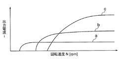
- FIG. 12 schematically shows output characteristics (output current vs. rotational speed characteristics) of a power generation coil required for a power supply device applied to a battery-less device.
- the horizontal axis of FIG. 12 shows the rotational speed N of the rotor of the generator, and the vertical axis shows the output current i of the generator coil.
- Curves a and b in FIG. 12 show the output characteristics of the power generation coil for driving the control system load (third load) and the constant drive load (first load), respectively, and the curve c shows the drive load (first load) at any time.
- 2 shows the output characteristics of the power generating coil for driving the load 2).
- the power generation coil for driving the control system load needs to drive the load from the very low speed rotation immediately after the start operation of the engine is started as shown by the curve a in FIG. It is necessary to have it wrapped. Increasing the number of turns of the power generation coil causes the output to saturate or decrease during high-speed rotation of the engine, but does not cause a problem because the power required to drive the control system load is small.
- the power generation coil that drives a constantly driven load not only needs to generate the output necessary to drive the load even at the engine rotation speed, but also needs to generate a certain amount of output even at high engine speeds. Therefore, it is necessary to reduce the number of turns as compared with the power generation coil that drives the control system load. Therefore, the output characteristics of the power generation coil that drives the constantly driven load are higher than the rotational speed at which the output of the power generation coil that drives the control system load rises, as shown by the curve b in FIG. 12, and sufficiently higher than the idling rotational speed of the engine. The output rises at a very low rotational speed, and has a characteristic that generates a larger output than the power generation coil that drives the control system load when the engine rotates at high speed.
- the power generation coil that drives the drive load at any time may have insufficient output when the engine is started, but generates a sufficiently large output after the start of the engine is completed and does not decrease during high-speed rotation of the engine. Therefore, the number of turns is minimized. Therefore, as shown by the curve c in FIG. 12, the output characteristic rises at a rotational speed higher than the rotational speed at which the output of the power generating coil that constantly drives the driving load rises, and always drives the driving load when the engine rotates at high speed. It becomes a characteristic that generates a larger output than the power generating coil.
- the power supply device may be configured so that the output voltage of the power generating coil that drives the driving load can be boosted until the start of the engine is completed. Therefore, it has been conventionally performed to increase the output voltage of the power generation coil by performing chopper control for intermittently passing the energization current of the power generation coil that drives the driving load until the start of the engine is completed. As described above, there is a limit in increasing the output voltage during low-speed rotation only by chopper-controlling the current flowing through the power generation coil for boosting the output voltage.
- a power generation coil in this embodiment, a power generation coil that constantly drives a drive load
- first power generation coil a power generation coil that attempts to increase the power supplied to the load by performing chopper control that interrupts the energization current
- first power generation coil a power generation coil that attempts to increase the power supplied to the load by performing chopper control that interrupts the energization current
- second power generation coil the power generation coil that drives the drive load at any time
- the first power generation coil and the second power generation coil are magnetically and tightly coupled to each other.
- the first power generation coil has a larger number of turns than the second power generation coil, and the rotation speed of the internal combustion engine (rotation speed of the rotor of the generator) is higher than the idling rotation speed of the internal combustion engine. From the first power generation coil and the second power generation coil when the engine speed increases to a first set speed set low and when the engine speed increases to a second set speed higher than the first set speed, respectively. The output of the load current is started.
- the power generation coil that drives the control system load is referred to as a “third power generation coil”, and this power generation coil supplies the load current at a lower rotational speed than the rotational speed at which the first power generation coil starts supplying the load current. In order to be able to start, winding is performed with a greater number of turns than the first power generation coil.
- FIG. 1 shows an electrical configuration of a first embodiment of a power supply device for an internal combustion engine according to the present invention.
- Wa and Wb are first and second power generation coils provided in an AC generator driven by an internal combustion engine, respectively, and Ld1 and Ld2 are supplied with power from the first power generation coil and the second power generation coil, respectively.
- VC1 is a first voltage conversion circuit that converts the output voltage of the first power generation coil Wa into a DC voltage supplied to the first load Ld1
- VC2 is the output voltage of the second power generation coil Wb that is the second load Ld2.
- CS is a second voltage conversion circuit for converting the DC voltage supplied to the second voltage conversion circuit VC2 and the second load Ld2 between the second voltage conversion circuit VC2 and the second load Ld2.
- the AC / DC conversion circuit that converts the AC output voltage of the generator into the DC voltage supplied to the first load Ld1 and the second load Ld2 is configured by the voltage conversion circuits VC1 and VC2 and the energization control switch CS. .
- the upper arm of the two legs of the bridge is configured by diodes D11 and D12, and the lower arm of the two legs is configured by MOSFETs F11 and F12. It is made up of.
- the first switch means is constituted by the MOSFETs F11 and F12 constituting the lower arm of the first bridge circuit B1, and the diodes D11 and D12 constituting the upper arm of the first bridge circuit B1.
- a first full-bridge rectifier circuit is formed by parasitic diodes Dp11 and Dp12 formed between the drains and sources of MOSFETs F11 and F12 constituting the lower arm of the first bridge circuit B1.
- connection point a1 between the anode of the diode D11 and the drain of the MOSFET F11 and the connection point b1 between the anode of the diode D12 and the drain of the MOSFET F12 are input terminals of the first rectifier circuit.
- a voltage induced in one power generation coil Wa is input.
- the common connection point of the cathodes of the diodes D11 and D12 and the common connection point of the sources of the MOSFETs F11 and F12 are the output terminals c1 and d1 on the positive side and the negative side of the first rectifier circuit, respectively. Is connected to a smoothing capacitor C1.
- Load connection terminals e1 and f1 are drawn from output terminals c1 and d1 of the first rectifier circuit, and a first load Ld1 is connected between these load connection terminals.
- the upper arm of the two legs of the bridge is configured by diodes D21 and D22, and the lower arm of the two legs is configured by MOSFETs F21 and F22. It is made up of.
- the second switch means is constituted by MOSFETs F21 and F22 constituting the lower arm of the second bridge circuit B2, and the diodes D21 and D22 constituting the upper arm of the second bridge circuit B2 and the second A full bridge type second rectifier circuit is constituted by the parasitic diodes Dp21 and Dp22 formed between the drains and sources of the MOSFETs F21 and F22 constituting the lower arm of the second bridge circuit B2.
- connection point a2 between the anode of the diode D21 and the drain of the MOSFET F21 and the connection point b2 between the anode of the diode D22 and the drain of the MOSFET F22 are input terminals of the second rectifier circuit,
- the voltage induced in the second power generation coil Wb is input.
- the common connection point of the cathodes of the diodes D21 and D22 and the common connection point of the sources of the MOSFETs F21 and F22 are respectively the positive and negative output terminals c2 and d2 of the second rectifier circuit.
- the positive side load connection terminal e2 is drawn out from c2 through the energization control switch CS.
- a minus side load connection terminal f2 is drawn from the minus side output terminal d2 of the second rectifier circuit, and the second load Ld2 is connected between the load connection terminals e2 and f2 via the switch SW.
- a smoothing capacitor C2 is also connected between the output terminals c2 and d2 of the second rectifier circuit via an energization control switch CS for controlling energization to the second load.
- the energization control switch CS is composed of a switching element that can be turned on and off, such as a MOSFET, and is controlled by a switch control unit described later.
- the switch SW is a switch that is closed when the second load Ld2 is operated after the internal combustion engine is started, and includes a switch element that can be turned on and off.
- a CU is a switch control unit that controls a first switch means constituted by MOSFETs F11 and F12, a second switch means constituted by MOSFETs F21 and F22, and an energization control switch CS. It is.
- the switch control unit CU is provided with a sufficiently large number of turns in the generator and outputs a constant DC voltage Vcc using a third power generation coil Wc that outputs a voltage from an extremely low speed of the internal combustion engine as a power source.
- the power supply circuit PS operates by being supplied with a power supply voltage.
- the illustrated switch control unit CU includes a first power generation coil for operating the first load (always driving load in the present embodiment) Ld1 in a region where the rotational speed of the engine is low, such as when the internal combustion engine is started.
- the induced voltage of Wa is boosted and the DC voltage applied to the first load Ld1 needs to be higher than the voltage obtained when the induced voltage of the first power generation coil Wa is rectified as it is (
- the energization control switch CS is turned off to keep the second voltage conversion circuit from energizing the second load,
- the voltage supplied to the first load Ld1 in the state where the energization control switch CS is turned on / off so as to limit the current flowing from the second power generation coil Wb to the second load Ld2 (a state in which PWM control is performed).
- both the first switch means (MOSFETs F11 and F12)) and the second switch means (MOSFETs F21 and F22) are controlled to be turned on and off, and the current flowing through the first power generation coil Wa and the second power generation coil
- the chopper control of both the current flowing through Wb is performed simultaneously.
- the first and second power generation coils Wa and Wb are provided in an AC generator driven by an internal combustion engine.
- a magnet generator in which the rotor field is composed of permanent magnets is used as an AC generator driven by an internal combustion engine.
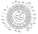
- the magnet generator used in this embodiment is configured as shown in FIG.
- 1 is an 18-pole magnet rotor and 2 is an 18-pole stator.
- the magnet rotor 1 includes a cup-shaped rotor yoke (flywheel) 101 and 18 permanent magnets M1 to M18 fixed to the inner periphery of the peripheral wall portion 101a of the rotor yoke 101 at equal angular intervals.
- the series of permanent magnets M1 to M18 are alternately magnetized in the radial direction of the rotor yoke, thereby forming an 18-pole magnet field inside the peripheral wall of the rotor yoke 101. ing.
- the stator 2 includes an armature core 201 having a structure in which 18 tooth portions T1 to T18 project radially from an outer peripheral portion of the annular yoke Y at equal angular intervals, and a series of tooth portions T1 of the armature core 201. To unit coils W1 to W18 wound around T18, respectively.
- the stator 2 is fixed to an engine case, a cover or the like in a state of being concentrically disposed inside the magnet rotor 1, and a magnetic pole portion formed at each tip of the tooth portions T1 to T18 of the armature core.
- the magnet rotor 1 is opposed to the magnetic poles M1 to M18 via a gap.
- the unit coils W1 to W18 provided in the stator 2 are connected so as to constitute the first to third power generation coils Wa to Wc.
- the first power generation coil Wa is connected to a plurality of unit coils wound around a plurality of tooth portions arranged alternately, among the tooth portions provided on the armature core.
- the second power generation coil Wb is a tooth portion around which any of a plurality of unit coils constituting the first power generation coil is wound out of the tooth portions provided in the armature core.
- the third power generation coil Wc is configured by connecting other unit coils.
- unit coils W2, W4, W6, W8, which are alternately arranged, out of a series of unit coils W1 to W18 wound around the tooth portions T1 to T18 of the armature core, respectively.
- W10 and W12 are connected in series to form a first power generation coil Wa, and tooth portions T2, T4, T6, T8, in which unit coils W2, W4, W6, W8, W10 and W12 are wound, respectively.
- the second power generation coil Wb is configured by being connected in series.
- the other five unit coils W14 to W18 are connected in series to constitute a third power generation coil Wc.
- the switch control unit CU is configured as shown in FIG. 2, for example.
- reference numeral 10 denotes a drive signal supply circuit for supplying drive signals to the MOSFETs F11 and F12 constituting the first switch means 11 and the MOSFETs F21 and F22 constituting the second switch means 12.
- the drive signal supply circuit 10 includes a zero cross point of the output voltage of the first generator coil W1 (a zero cross point when the output voltage shifts from a negative half wave to a positive half wave, and a negative half wave from the positive half wave.
- Output of the zero cross detection circuit 13 for detecting the peak point of the output voltage of the first generator coil W1, and the output of the peak detection circuit 14 for detecting each peak point of the output voltage of the first generator coil W1.
- the output of the rejection determination means 15 is input.
- the drive signal supply circuit 10 simultaneously applies a drive signal having a pulse waveform to the gates of the MOSFETs F11 and F12 and the MOSFETs F21 and F22 when it is necessary to increase the voltage induced in the first power generation coil Wa.
- a drive signal having a pulse waveform to the gates of the MOSFETs F11 and F12 and the MOSFETs F21 and F22 when it is necessary to increase the voltage induced in the first power generation coil Wa.
- the first power generation coil Wa is turned on and off.
- the chopper control of the flowing current and the chopper control of the current flowing through the second power generation coil Wb are simultaneously performed.
- the drive signal supply circuit 10 used in this embodiment detects a peak after the zero cross detection circuit 13 detects each zero cross point of the output voltages of the power generation coils Wa and Wb when it is necessary to perform a boost operation. Until the circuit 14 detects the peak point, a high level drive signal is simultaneously applied to the gates of the MOSFETs F11, F12 and F21, F22 constituting the first switch means and the second switch means to provide the first switch. The first switch means and the second switch means are turned on at the same time, from when the peak detection circuit 14 detects each peak point to when the zero cross detection circuit 13 detects the zero cross point.
- the drive signal applied to the MOSFETs constituting the switch means is set to zero level so that the first switch means and the second switch means are simultaneously turned off. It is.
- the boosting necessity determination means 15 is a means for determining whether or not it is necessary to boost the induced voltage of the first power generation coil Wa.
- the boosting necessity determination means 15 shown in the figure is set to a speed suitable for determining that the engine has been started, with the rotation speed detected by the rotation speed detection means 16 for detecting the rotation speed of the internal combustion engine.
- the rotational speed of the internal combustion engine is lower than the set speed (when the start of the engine is not completed) as compared with the set speed (start completion speed) as compared with the set speed (start completion speed)
- start completion speed the output voltage of the first power generation coil needs to be boosted.
- a drive signal output command is given to the drive signal supply circuit 10, and an off command is given to the energization control switch CS to turn off the energization control switch.
- the boosting necessity determination means 15 also determines that the need for boosting has disappeared when the rotational speed of the internal combustion engine is equal to or higher than the set speed (when the engine has been started), and sends a drive signal to the drive signal supply circuit 10. In addition to giving a stop command, an on command is given to the energization control switch CS to turn on the energization control switch.
- Rotational speed detection means 16 detects the rotational speed of the engine by an arbitrary method.
- the rotational speed detecting means 16 can be configured to detect the rotational speed of the engine from the time from when the zero cross detection circuit 13 detects each zero cross point until the next zero cross point is detected.
- the rotation speed of the engine is detected from the interval at which the signal generator generates a pulse. be able to.
- FIG. 8 shows an example of voltage and current waveforms indicating the operation of the power supply device according to this embodiment.
- FIG. 8A shows the waveform of the alternating voltage induced in the first power generation coil Wa and the second power generation coil Wb when the crankshaft of the engine rotates, and FIG. Drive signals V11, V12, and V21, V22 given to the MOSFETs F11, F12, F21 and F22 are shown.
- FIG. 8C shows the waveform of a direct current output from the first power generation coil Wa through the first voltage conversion circuit VC1
- FIG. 8D shows the first voltage from the first power generation coil Wa.
- the waveform of the DC voltage output through the conversion circuit VC1 is shown.
- FIG. 8E shows a change in DC power output from the first power generation coil Wa through the first voltage conversion circuit VC1.
- the drive signal supply circuit 10 is in a high level state from when the zero cross detection circuit 13 detects each zero cross point of the induced voltage of the first generator coil Wa until the peak detection circuit 14 detects the peak point.
- the rectangular-wave drive signals V11 and V12 that hold the zero level from when the peak detection circuit detects the peak point of the induced voltage of the power generation coil Wa until the zero cross detection circuit 13 detects the zero cross point are held. Apply simultaneously to the gates of MOSFETs F11 and F12.
- the drive signal supply circuit 10 also detects the peak point of the second power generation coil Wb after the zero cross detection circuit 13 detects each zero cross point of the induced voltage of the second power generation coil Wb. Until the zero cross detection circuit 13 detects the zero cross point after the peak detection circuit 14 detects the peak point of the induced voltage of the generator coil Wb.
- the rectangular-wave drive signals V21 and V22 are simultaneously applied to the gates of the MOSFETs F21 and F22.
- the first power generation coil Wa and the second power generation coil Wb are closely magnetically coupled, and the power from the second power generation coil Wb to the second load Ld2 Since the supply is stopped, a large part of the energy (L ⁇ i 2 ) / 2 released from the second power generation coil when the current flowing through the second power generation coil Wb is interrupted is the first.
- the energy released from the first power generation coil can be superimposed. Therefore, the voltage induced in the first power generation coil Wa can be made higher than the voltage induced when only the current flowing through the first power generation coil Wa is cut off.
- the voltage induced in the first power generation coil is made higher than the voltage induced when only the current flowing through the first power generation coil is cut off. Therefore, when the power supply device of the present embodiment is applied to a batteryless internal combustion engine drive device, the output voltage of the first power generation coil is raised at a lower rotational speed than before when starting the engine, It is possible to improve the startability of the engine by driving a constant drive load such as a fuel pump from a low speed rotation.
- the phase difference between the two voltages is very small, so that the boosting operation is caused by the phase difference between the two voltages. There will be no hindrance.
- the inventor of the present invention relates to chopper control performed assuming that an output is obtained from the first power generation coil in a state where the first power generation coil and the second power generation coil are magnetically tightly coupled, and the effect of the chopper control.
- the following three types of control were conducted. (1) Chopper-controlled both the first power generation coil Wa and the second power generation coil having a smaller number of turns than the first power generation coil. (2) Chopper control is performed only on the first power generation coil Wa. (3) Chopper control is performed only on the second power generation coil Wb.
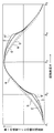
- FIG. 9 schematically shows changes in the amount of magnetic flux interlinked with the first power generation coil Wa when the controls (1) to (3) are performed, with respect to the rotation angle ⁇ of the rotor.
- a curve a shows a change in the amount of magnetic flux interlinked with the first power generation coil as the magnet rotor rotates at no load
- a curve b shows the first power generation coil Wa without the chopper control.
- a change in the amount of magnetic flux linked to the first power generation coil when the output is subjected to full-wave rectification is shown.
- Curve c shows the change in the amount of magnetic flux interlinked with the first power generation coil when the second power generation coil Wb is in a no-load state and only the current flowing through the first power generation coil Wa is chopper-controlled. Shows a change in the amount of magnetic flux interlinking with the first power generation coil when the first power generation coil is in a no-load state and only the current flowing through the second power generation coil Wb is chopper-controlled.
- Curve e shows the change in the amount of magnetic flux interlinked with the first power generation coil Wa when both the current flowing through the first power generation coil Wa and the current flowing through the second power generation coil Wb are chopper-controlled. Yes.
- the positions of the angles ⁇ 1, ⁇ 3, and ⁇ 5 shown on the horizontal axis are positions where the current starts to flow through the respective power generation coils
- the position of the angle ⁇ 2 and the position of the angle ⁇ 4 are positions where the current that has been flowing so far is cut off.
- the first voltage conversion circuit VC1 that converts the output voltage of the first power generation coil Wa into a DC voltage
- the first voltage is generated along with the rotation of the magnet rotor as indicated by a curve a in FIG.
- the amount of magnetic flux interlinked with the power generation coil Wa changes in a substantially sine wave shape. Further, even when the chopper control is not performed for either the first power generation coil Wa or the second power generation coil Wb, the amount of magnetic flux interlinked with the first power generation coil Wa is accompanied by the rotation of the rotor. As shown by a curve b in FIG.
- the current flowing through the second power generation coil Wb when only the current flowing through the second power generation coil Wb is chopper-controlled while keeping the first power generation coil Wa in a no-load state, the current flowing through the second power generation coil Wa at the positions of the angles ⁇ 2 and ⁇ 4 Since the change in magnetic flux generated when the power is interrupted is superimposed on the change in the amount of magnetic flux interlinked with the first power generation coil that is magnetically tightly coupled, the amount of magnetic flux interlinked with the first power generation coil As shown in the curve d, the amount of magnetic flux interlinking with the first power generation coil at the positions of the angles ⁇ 2 and ⁇ 4 changes more than the sinusoidal change when chopper control is not performed. It is shown that the boosted voltage is induced in the first power generation coil Wa due to the change in the amount of magnetic flux.
- the current flowing through the first power generation coil Wa when both the current flowing through the first power generation coil Wa and the current flowing through the second power generation coil Wb are chopper-controlled, the current flowing through the first power generation coil Wa at the position of the angle ⁇ 2 and the position of the angle ⁇ 4 Magnetic flux generated when the current flowing through the second power generation coil is interrupted due to a change in the amount of magnetic flux interlinked with the first power generation coil when the current flowing through the second power generation coil Wb is simultaneously interrupted. Since the change in the amount is superimposed, the amount of magnetic flux interlinking with the first power generation coil Wa is obtained when the current flowing through the first power generation coil is chopper-controlled as shown by the curve e in FIG. It shows a greater change than c).
- the first current is cut off when the energization current is cut off at the position of the angle ⁇ 2 and the position of the angle ⁇ 4.
- the voltage induced in the power generation coil Wa is higher than that in the case where only the current flowing through the first power generation coil Wa is chopper-controlled (in the case of the curve c).
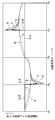
- FIG. 10 shows a waveform a of a voltage induced in the first power generation coil when neither the current flowing through the first power generation coil nor the current flowing through the second power generation coil is chopper-controlled, and the first power generation
- the voltage b induced in the first power generation coil when only the current flowing through the coil is chopper-controlled, and the voltage induced in the first power generation coil when only the current flowing through the second power generation coil is chopper-controlled.
- a waveform c and a waveform d of a voltage induced in the first power generation coil Wa when both the current flowing in the first power generation coil and the current flowing in the second power generation coil are chopper-controlled.
- only the current flowing through the first power generation coil is controlled by simultaneously performing chopper control on both the current flowing through the first power generation coil and the current flowing through the second power generation coil.
- a higher voltage can be output from the first power generation coil than when chopper control is performed.
- FIG. 11 shows the first output from the first power generation coil Wa through the first voltage conversion circuit VC1 when the voltage output from the first power generation coil shows the waveforms a, b, c and d in FIG.
- the change of the direct-current power supplied to load Ld1 is shown.
- a curve a in FIG. 11 indicates that the first voltage conversion circuit from the first power generation coil Wa when the current flowing through the first power generation coil Wa and the current through the second power generation coil Wb are not chopper-controlled.
- the change of the DC power supplied to the load through VC1 is shown, and curve b shows the load from the first power generation coil Wa through the first voltage conversion circuit VC1 when only the current flowing through the first power generation coil Wa is chopper-controlled.
- Curve c shows a change in the DC power supplied from the first power generation coil Wa to the load through the first voltage conversion circuit VC1 when only the current flowing through the second power generation coil Wb is chopper-controlled. Is supplied from the first power generating coil Wa to the load through the first voltage conversion circuit VC1 when both the current flowing through the first power generating coil Wa and the current flowing through the second power generating coil Wb are simultaneously controlled by chopper control. It shows the change in DC power.
- the current flowing through the first power generation coil Wa and the current flowing through the second power generation coil Wb are simultaneously controlled by chopper control, so that only the current flowing through the first power generation coil Wa is chopper controlled. It can be seen that an output larger than the output supplied to the load from the first power generation coil Wa can be obtained from the first power generation coil.
- the MOSFETs F11, F12, F21, and F22w are simultaneously turned on and off, and both the current flowing through the first power generation coil Wa and the current flowing through the second power generation coil Wb are simultaneously controlled by chopper control, and induced in the first power generation coil Wa.
- the energy released from the second power generation coil when the current flowing through the second power generation coil Wb is cut off is transferred to the second load Ld2 side. It is desirable to prevent absorption and loss and transfer as much energy released from the second power generation coil as possible to the first power generation coil.
- the energization control switch CS is turned off, and the second power generation coil Power is not supplied from Wb to the second load Ld2.
- the energization control switch CS when the current flowing through the first power generating coil and the current flowing through the second power generating coil are both chopper controlled to increase the output of the first power generating coil, although the energization control switch CS provided between the second load Ld2 and the energization control switch CS is kept off, the energization control switch CS is turned on and off at a predetermined duty ratio instead of keeping the energization control switch CS in an off state. (The power supplied from the second power generation coil Wb to the second load Ld2 through the second voltage conversion circuit VC2 is PWM-controlled), so that the power supplied from the second power generation coil to the second load is changed.
- the current flowing through the first power generation coil and the current flowing through the second power generation coil may be controlled by chopper simultaneously.
- the voltage value output from the first power generation coil can be adjusted by controlling the on-duty ratio of the energization control switch CS.
- the first cross-point is detected so that the zero crossing point and the peak point of the induced voltage of the power generating coil are detected, the current starts to flow through the power generating coil at the zero crossing point of the induced voltage, and the current is cut off at the peak point.
- the switch means and the second switch means are turned on and off, the way to turn on and off the first switch means and the second switch means is not limited to that shown in the above embodiment.
- a pulse signal having a frequency higher than the maximum value of the output frequency of the first power generation coil and the second power generation coil is simultaneously applied as a drive signal to the gates of MOSFETs constituting the first switch means and the second switch means.
- the current flowing through the first power generation coil and the second power generation coil may be intermittently provided at a frequency sufficiently higher than the maximum frequency of the output voltage of both power generation coils.
- the zero cross detection circuit and the peak detection circuit can be omitted from the switch control unit CU.
- the switch control unit CU is preferably configured to synchronize the on / off control of the first switch means and the on / off control of the second switch means as in the above embodiment.
- the on / off control of the switch means and the on / off control of the second switch means are performed at a frequency sufficiently higher than the maximum frequency of the output voltage of the first and second power generating coils, the on / off of the first switch means is performed.
- the control and the on / off control of the second switch means may be performed asynchronously.
- the switch SW for determining whether or not the load Ld2 is energized is provided, the switch SW may be omitted, and the energization control switch CS may be configured to also function as the switch SW.
- the energization control switch CS is inserted between the second voltage conversion circuit VC2 and the second load Ld2.
- the energization control switch is connected to the second voltage conversion circuit from the second voltage conversion circuit. Any switch can be used as long as it can control the energization of the load, and the switch is not necessarily inserted between the second voltage conversion circuit VC2 and the second load Ld2.
- the upper arm and the lower arm of the two legs of the second bridge circuit B2 constituting the second voltage conversion circuit VC2 are constituted by thyristors Th1 and Th2 and MOSFETs F21 and F22, respectively.
- the MOSFETs F21 and F22 constitute the second switch means, and are formed between the thyristors constituting the upper arm of the second bridge circuit B2 and the drains and sources of the MOSFETs F21 and F22 constituting the lower arm.
- a second rectifier circuit may be configured by a parasitic diode, and the thyristors Th1 and Th2 may have a function as an energization control switch.
- the switch control unit CU stops supplying the trigger signal to the thyristors Th1 and Th2 of the second voltage conversion circuit VC2 until the start of the internal combustion engine is completed, and after the start of the internal combustion engine is completed, the thyristor A trigger signal is supplied to Th1 and Th2.
- the inductance L of the second power generation coil Wb can be made larger than the inductance of the first power generation coil Wa, Even if the current flowing through the first power generating coil Wa is not chopper-controlled, the energy released from the second power generating coil Wb when the current flowing through the second power generating coil Wb is cut off.
- the induced voltage of the first power generation coil Wa can boost the only current flowing in the generator coil Wa of the first to a higher voltage than if you choose to chopper control.
- the voltage output from the first power generation coil needs to be higher than when only the current flowing through the first power generation coil is chopper-controlled, but the current flowing through the first power generation coil and the second If it is not necessary to increase the voltage obtained when both currents flowing through the power generation coil are chopper-controlled, the number of turns of the second power generation coil Wb is set to be larger than the number of turns of the first power generation coil Wa.
- the voltage output from the first power generation coil can be boosted by chopper-controlling only the current flowing through the second power generation coil Wb.
- the first voltage conversion circuit VC1 Is constituted by a full-bridge type diode bridge rectifier circuit including diodes D11 and D12 constituting the upper arm of the bridge and diodes Da1 and Da2 constituting the lower arm of the bridge, and the second voltage conversion circuit VC2 Only is constituted by a mixed bridge circuit of diodes D21 and D22 and MOSFETs F21 and F22.
- the switch control unit CU turns off the energization control switch CS to prevent energization from the second voltage conversion circuit to the second load, or from the second power generation coil Wb to the second load.
- each unit coil constituting the first power generation coil Wa is replaced with the second power generation coil Wb.
- the unit coil forming each pair of the first power generation coil and the second power generation coil is wound around the same tooth portion of the armature core, The first power generation coil and the second power generation coil may be magnetically tightly coupled.
- the first power generation coil Wa is composed of unit coils W1a to W13a
- the second power generation coil Wb is composed of unit coils W1b to W13b.
- the unit coils W1a to W13a are paired with the unit coils W1b to W13b, respectively, and the unit coils (W1a, W1b), (W2a, W2b),.
- the iron core is wound around the tooth portions T1 to T13.
- the unit coils forming each pair are wound around the same tooth portion in a state of being arranged in the radial direction of the armature core, but the unit coils forming a pair are wound around the same tooth portion. It may be.
- the first generator coil or the third generator coil is provided in the generator, but another generator coil may be provided in the generator.
- the first switch means and the second switch means provided in the voltage conversion circuit are constituted by MOSFETs, but the first switch means and the second switch means are other types that can be controlled on and off. What is necessary is just to comprise by a semiconductor switch element, and a 1st switch means and a 2nd switch means can also be comprised by other switch elements, such as IGBT.
- the switch elements constituting the first switch means and the second switch means do not have a parasitic diode, the diodes are arranged in parallel with the switch elements constituting the first switch means and the second switch means, respectively. Is connected.
- the diode or thyristor is disposed on the upper arm of the bridge, and the first switch means or the first
- the switch element (MOSFET in the above embodiment) constituting the second switch means is disposed on the lower arm of the bridge, the first switch means and the second switch means are switched on when they are turned on.
- the first generator coil and the second generator coil may be provided so as to be short-circuited.
- the switch element constituting the first switch means or the second switch means is disposed on the upper arm of the bridge circuit, and the diode or thyristor is provided. It may be arranged on the lower arm of the bridge.
- the generator is configured to output a single-phase AC voltage, but the present invention can also be applied to a case where the generator is configured to output a three-phase AC voltage.
Landscapes
- Engineering & Computer Science (AREA)
- Power Engineering (AREA)
- Control Of Eletrric Generators (AREA)
Priority Applications (5)
| Application Number | Priority Date | Filing Date | Title |
|---|---|---|---|
| US15/744,200 US10263554B2 (en) | 2015-07-17 | 2015-07-17 | Power supply device for internal combustion engine |
| EP15898861.8A EP3327924A4 (de) | 2015-07-17 | 2015-07-17 | Stromversorgungsvorrichtung für verbrennungsmotor |
| PCT/JP2015/070494 WO2017013699A1 (ja) | 2015-07-17 | 2015-07-17 | 内燃機関用電源装置 |
| JP2017529175A JP6445698B2 (ja) | 2015-07-17 | 2015-07-17 | 内燃機関用電源装置 |
| CN201580081776.3A CN107925372A (zh) | 2015-07-17 | 2015-07-17 | 内燃机用电源装置 |
Applications Claiming Priority (1)
| Application Number | Priority Date | Filing Date | Title |
|---|---|---|---|
| PCT/JP2015/070494 WO2017013699A1 (ja) | 2015-07-17 | 2015-07-17 | 内燃機関用電源装置 |
Publications (1)
| Publication Number | Publication Date |
|---|---|
| WO2017013699A1 true WO2017013699A1 (ja) | 2017-01-26 |
Family
ID=57834101
Family Applications (1)
| Application Number | Title | Priority Date | Filing Date |
|---|---|---|---|
| PCT/JP2015/070494 Ceased WO2017013699A1 (ja) | 2015-07-17 | 2015-07-17 | 内燃機関用電源装置 |
Country Status (5)
| Country | Link |
|---|---|
| US (1) | US10263554B2 (de) |
| EP (1) | EP3327924A4 (de) |
| JP (1) | JP6445698B2 (de) |
| CN (1) | CN107925372A (de) |
| WO (1) | WO2017013699A1 (de) |
Families Citing this family (2)
| Publication number | Priority date | Publication date | Assignee | Title |
|---|---|---|---|---|
| US11428116B2 (en) | 2019-11-29 | 2022-08-30 | Pratt & Whitney Canada Corp. | System and method for measuring an axial position of a rotating component of an engine |
| CN111555645B (zh) * | 2020-04-09 | 2022-01-11 | 北京中航智科技有限公司 | 一种输出可控电压的稳压电路 |
Citations (5)
| Publication number | Priority date | Publication date | Assignee | Title |
|---|---|---|---|---|
| JPH11234992A (ja) * | 1998-02-13 | 1999-08-27 | Kokusan Denki Co Ltd | 磁石式交流発電機を用いた電源装置 |
| US6414400B1 (en) * | 1999-02-03 | 2002-07-02 | Coleman Powermate, Inc. | Small engine driven generator |
| JP2003079004A (ja) * | 2001-09-05 | 2003-03-14 | Nissan Motor Co Ltd | 車両の発電駆動制御装置 |
| JP2005245144A (ja) * | 2004-02-27 | 2005-09-08 | Hitachi Ltd | 車両駆動装置 |
| JP2013146131A (ja) * | 2012-01-13 | 2013-07-25 | Kokusan Denki Co Ltd | 直流電源装置 |
Family Cites Families (20)
| Publication number | Priority date | Publication date | Assignee | Title |
|---|---|---|---|---|
| US4328427A (en) * | 1980-07-07 | 1982-05-04 | General Electric Company | Smooth series parallel transition for dual winding traction alternator |
| US4539515A (en) * | 1982-03-18 | 1985-09-03 | Mitsubishi Denki Kabushiki Kaisha | Vehicular direct-current three-wire electric system |
| US5057763A (en) * | 1988-09-12 | 1991-10-15 | Nippondenso Co., Ltd. | High power supply for motor vehicle |
| JP3161241B2 (ja) | 1994-05-12 | 2001-04-25 | 国産電機株式会社 | 内燃機関用電源装置 |
| JP3161232B2 (ja) * | 1994-07-05 | 2001-04-25 | 国産電機株式会社 | 内燃機関用電源装置 |
| US5808451A (en) * | 1995-12-29 | 1998-09-15 | Kokusan Denki Co., Ltd. | Power device for internal combustion engine |
| US6111390A (en) | 1998-01-20 | 2000-08-29 | Kokusan Kenki Co., Ltd. | Magneto-equipped power device |
| US6674180B2 (en) * | 2001-10-12 | 2004-01-06 | Ford Global Technologies, Llc | Power supply for a hybrid electric vehicle |
| JP2004068792A (ja) * | 2002-08-09 | 2004-03-04 | Kokusan Denki Co Ltd | 内燃機関用燃料噴射・点火装置 |
| JP2006345592A (ja) * | 2005-06-07 | 2006-12-21 | Fuji Seratekku Kk | 極低速で回転する高出力発電機 |
| JP4285458B2 (ja) * | 2005-08-08 | 2009-06-24 | トヨタ自動車株式会社 | 車両の電源装置およびその制御方法 |
| US20080122463A1 (en) * | 2006-06-30 | 2008-05-29 | Sanjay Dabral | Testing microelectronic devices using electro-optic modulator probes |
| JP2008133735A (ja) * | 2006-11-27 | 2008-06-12 | Kokusan Denki Co Ltd | 電子式制御ユニット |
| DE102008023332B4 (de) * | 2008-05-13 | 2010-12-02 | Siemens Aktiengesellschaft | Dieselelektrisches Antriebssystem |
| CN102237842A (zh) * | 2010-04-23 | 2011-11-09 | 鸿富锦精密工业(深圳)有限公司 | 磁场产生及控制电路 |
| DE102011003940A1 (de) * | 2011-02-10 | 2012-08-16 | Robert Bosch Gmbh | System mit einer elektrisch erregten Maschine |
| US9358898B2 (en) * | 2011-12-15 | 2016-06-07 | Toyota Jidosha Kabushiki Kaisha | Hybrid vehicle |
| US9425726B2 (en) * | 2013-06-25 | 2016-08-23 | Masdar Institute Of Science And Technology | Fault-tolerant wind energy conversion system |
| US10355628B2 (en) * | 2015-10-01 | 2019-07-16 | Shindengen Electric Manufacturing Co., Ltd. | Starting power generation apparatus and starting power generation method |
| JP2017154637A (ja) * | 2016-03-02 | 2017-09-07 | トヨタ自動車株式会社 | 自動車 |
-
2015
- 2015-07-17 EP EP15898861.8A patent/EP3327924A4/de not_active Withdrawn
- 2015-07-17 CN CN201580081776.3A patent/CN107925372A/zh active Pending
- 2015-07-17 US US15/744,200 patent/US10263554B2/en not_active Expired - Fee Related
- 2015-07-17 JP JP2017529175A patent/JP6445698B2/ja not_active Expired - Fee Related
- 2015-07-17 WO PCT/JP2015/070494 patent/WO2017013699A1/ja not_active Ceased
Patent Citations (5)
| Publication number | Priority date | Publication date | Assignee | Title |
|---|---|---|---|---|
| JPH11234992A (ja) * | 1998-02-13 | 1999-08-27 | Kokusan Denki Co Ltd | 磁石式交流発電機を用いた電源装置 |
| US6414400B1 (en) * | 1999-02-03 | 2002-07-02 | Coleman Powermate, Inc. | Small engine driven generator |
| JP2003079004A (ja) * | 2001-09-05 | 2003-03-14 | Nissan Motor Co Ltd | 車両の発電駆動制御装置 |
| JP2005245144A (ja) * | 2004-02-27 | 2005-09-08 | Hitachi Ltd | 車両駆動装置 |
| JP2013146131A (ja) * | 2012-01-13 | 2013-07-25 | Kokusan Denki Co Ltd | 直流電源装置 |
Non-Patent Citations (1)
| Title |
|---|
| See also references of EP3327924A4 * |
Also Published As
| Publication number | Publication date |
|---|---|
| US20180205336A1 (en) | 2018-07-19 |
| JP6445698B2 (ja) | 2018-12-26 |
| US10263554B2 (en) | 2019-04-16 |
| EP3327924A4 (de) | 2019-04-17 |
| EP3327924A1 (de) | 2018-05-30 |
| JPWO2017013699A1 (ja) | 2018-04-26 |
| CN107925372A (zh) | 2018-04-17 |
Similar Documents
| Publication | Publication Date | Title |
|---|---|---|
| CN1037478C (zh) | 单相电子换向电动机系统及其方法 | |
| EP3767095B1 (de) | Motorrad mit einem einzylinder-motor | |
| EP3064762B1 (de) | Grätschsitzfahrzeug mit motoreinheit | |
| US9716455B2 (en) | Power conversion device and method of controlling the same | |
| CN103348585A (zh) | 旋转电机驱动系统 | |
| CN101635558A (zh) | 逆变器式发电机 | |
| CN103780042A (zh) | 一种无刷直流磁阻式起动发电机 | |
| CN104242580A (zh) | 一种汽车用可变绕组起动发电机 | |
| CN108111089B (zh) | 开关磁阻马达用的控制装置 | |
| JP6445698B2 (ja) | 内燃機関用電源装置 | |
| JP5130143B2 (ja) | インバータ発電機 | |
| JP5690651B2 (ja) | インバータ発電機 | |
| CN111801882B (zh) | 逆变发电机 | |
| US9579982B2 (en) | Resonant motor system | |
| US7928676B2 (en) | Vehicle motor control apparatus | |
| JP4487736B2 (ja) | バッテリ充電装置 | |
| JP6590457B2 (ja) | 車両駆動制御装置及び車両駆動制御方法 | |
| Sun et al. | Driving switched reluctance motor by full-bridge converter with ring structure | |
| JP2000102279A (ja) | 内燃機関始動用電動機兼用発電機 | |
| JP2012244690A (ja) | インバータ発電機 | |
| CN102324825A (zh) | 电动车用五相永磁同步直流无刷电机 | |
| CN202268791U (zh) | 电动车用五相永磁同步直流无刷电机 | |
| JP2015070699A (ja) | スイッチトリラクタンスモータの制御回路 | |
| OA17778A (en) | Engine unit and vehicle | |
| JP2013110942A (ja) | 回転電機及び回転電機制御システム |
Legal Events
| Date | Code | Title | Description |
|---|---|---|---|
| 121 | Ep: the epo has been informed by wipo that ep was designated in this application |
Ref document number: 15898861 Country of ref document: EP Kind code of ref document: A1 |
|
| ENP | Entry into the national phase |
Ref document number: 2017529175 Country of ref document: JP Kind code of ref document: A |
|
| WWE | Wipo information: entry into national phase |
Ref document number: 15744200 Country of ref document: US |
|
| NENP | Non-entry into the national phase |
Ref country code: DE |
|
| WWE | Wipo information: entry into national phase |
Ref document number: 2015898861 Country of ref document: EP |