WO2017013702A1 - 歩行に適した靴の靴底 - Google Patents
歩行に適した靴の靴底 Download PDFInfo
- Publication number
- WO2017013702A1 WO2017013702A1 PCT/JP2015/070505 JP2015070505W WO2017013702A1 WO 2017013702 A1 WO2017013702 A1 WO 2017013702A1 JP 2015070505 W JP2015070505 W JP 2015070505W WO 2017013702 A1 WO2017013702 A1 WO 2017013702A1
- Authority
- WO
- WIPO (PCT)
- Prior art keywords
- groove
- bent
- shoe sole
- intersection
- extending
- Prior art date
- Legal status (The legal status is an assumption and is not a legal conclusion. Google has not performed a legal analysis and makes no representation as to the accuracy of the status listed.)
- Ceased
Links
Images






Classifications
-
- A—HUMAN NECESSITIES
- A43—FOOTWEAR
- A43B—CHARACTERISTIC FEATURES OF FOOTWEAR; PARTS OF FOOTWEAR
- A43B13/00—Soles; Sole-and-heel integral units
- A43B13/14—Soles; Sole-and-heel integral units characterised by the constructive form
Definitions
- the present invention relates to a shoe sole suitable for walking, for example, elderly people with low muscular strength.
- Patent Document 1 aims at a shoe sole with good running efficiency, and does not consider the stability of walking of elderly people.
- the shoe sole disclosed in Patent Document 2 has a plurality of bent grooves extending obliquely rearward from the inner side of the foot to the outer side of the foot along the arrangement of the MP joints of the first to fifth heels from the forefoot to the toes. It is arranged in the same direction up to the part. These multiple bends will dominate how the pedestrian's toe joint bends.
- Patent Document 2 aims to improve the walking stability of elderly people and infants.
- the invention of the same document has not been sufficiently studied on the walking mechanism of the elderly.
- Patent Document 3 aims to selectively change the degree of expansion and contraction in a specific portion of the upper. A large number of notches for separating the shoe sole in the front-rear direction are formed in almost the entire region of the shoe sole of the invention.
- an object of the present invention is to provide a shoe sole in which elderly people with reduced muscle strength can improve the stability performance during walking.
- FIG. 11 shows the arrangement of the shoe sole during the both-leg support period. As shown in this figure, the front and rear legs are grounded while being slightly opened from side to side. As shown by the dot pattern in FIG. 11, only the rear end S10 of the front shoe sole S1 is grounded, while only the front end S20 of the rear shoe sole S2 is grounded.
- the present inventor has found that the step SD of both legs and the walking angle ⁇ tend to be larger in the case of elderly people than in young people. The reason for this is considered that the elderly lose their muscular strength and balance ability with aging, and compensate for these decreases by increasing the step SD and the walking angle ⁇ .
- the ground reaction force F of the pedestrian shown in FIG. 12 (b) was measured for the left / right x component Fx and the up / down z component Fz in FIG.
- the value of the inclination angle 1 for one cycle of walking is shown in FIG. In FIG. 12 (c), it can be understood that the swing width W ⁇ of the tilt angle heel is maximized in the both-leg support period TE with the dot pattern.
- the present invention is a shoe sole, wherein the shoe sole includes a front longitudinal groove G0 extending at least in the longitudinal direction Y at a central portion 1C between the inner side M and the outer side L of the front foot portion 3, and a mother of the front foot portion.
- a first bent groove G1 which is disposed in front DF from the Ryukyu O1 and extends in at least the lateral direction X so as to intersect the front longitudinal groove G0 at a virtual first intersection C1;
- the first bent groove G1 extends from the central portion 1C toward the inner edge 11 to the inner bent portion G11, and extends obliquely forward from the central portion 1C toward the outer edge 10.
- the second angle ⁇ formed by the outer bent portion G10 and the front vertical groove G0 is larger than the first angle ⁇ formed by the inner bent portion G11 and the front vertical groove G0.
- a front longitudinal groove G0 extending in the longitudinal direction is provided in the central portion 1C.
- the first bending groove G1 disposed in front of the main ball O1 has an inner bending portion G11 extending from the central portion 1C toward the inner edge 11 rightward or obliquely rearward, and the central portion. And an outer bent portion G10 extending obliquely forward from the portion 1C toward the outer edge 10.
- the virtual first intersection C1 (second intersection C2) means that such an intersection cannot actually be seen with eyes.
- “so as to intersect at the intersection” means that the grooves do not have to actually intersect.
- the front longitudinal groove G0 is close to about 2 to 3 mm and does not intersect with the first bent groove G1.
- the second angle ⁇ formed by the outer bent portion G10 and the front vertical groove G0 is larger than the first angle ⁇ formed by the inner bent portion G11 and the front vertical groove G0. Therefore, the first bending groove G1 extending obliquely forward on the outside will make it easier to move the trajectory of the pressure center point of the toe portion inward during the both-leg support period TE when the step distance between the left and right feet is large. Thereby, stable toe grounding can be expected.
- the front longitudinal groove G0 and the first bent groove G1 can be specified by various definitions as will be described later.
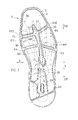
- FIG. 1 is a bottom view of a shoe sole showing Example 1 of the present invention.
- a dot pattern is given to the main groove portion.
- FIG. 2 is a schematic perspective view of the shoe sole.
- FIG. 2 and FIG. 8 to be described later, for convenience of drawing, the illustration of a thin groove formed on the grounding surface of the outsole is omitted.
- FIGS. 2 and 8 a dot pattern is attached to the part of the outsole.
- FIG. 3 is a schematic bottom view showing the sole with the foot skeleton.
- FIG. 4 is a schematic bottom view of the shoe sole. In FIG. 3 and FIG. 4, the illustration of thin grooves formed on the ground contact surface of the outsole is omitted in order to make the drawings easy to see. 5A, FIG.
- FIG. 5B, FIG. 5C, FIG. 5D, FIG. 5E and FIG. 5F are partial cross-sectional views of the shoe sole taken along the cross-sectional lines A, B, C, D, E, and F shown in FIG. .
- FIG. 6 is a bottom view of a shoe sole showing Example 2 of the present invention. In FIG. 7 and FIG. 9 described later, a dot pattern is given to the main groove portion.
- FIG. 7 is a bottom view of a shoe sole showing Example 3 of the present invention.
- FIG. 8 is a schematic perspective view of the shoe sole.
- FIG. 9 is a bottom view of a shoe sole showing Example 4 of the present invention.
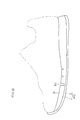
- FIG. 10 is a schematic side view of a shoe showing Example 5 of the present invention.
- FIG. 11 is a conceptual diagram showing the arrangement of left and right shoe soles in the both-leg support period TE.
- a dot pattern is attached to the ground contact portion.
- FIG. 12 is a graph showing the slope of ground reaction force in one cycle of walking.
- FIG. 13 is a graph showing the results of measuring the stability of the test samples T1 to T4.
- FIG. 14 is a graph showing the results of measuring the stability of the test samples T5 to T7.
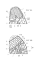
- FIG. 15A and FIG. 15B are bottom views of toe portions of shoe soles according to Examples 6 and 7, respectively.
- 16A and 16B are bottom views of a toe portion of a shoe sole showing Examples 8 and 9, respectively.
- a dot pattern is attached to the main groove portion.
- the front longitudinal groove G0 and the first bent groove G1 of the present invention are defined as follows in the first aspect. That is, in the first aspect, The average depth H0 of the front longitudinal groove G0 in the range from the first intersection C1 to 5 cm behind is set to 3 to 20 mm, The average depth H1 of the first bent groove G1 is set to 3 to 12 mm. “Average depth” means an average value obtained by averaging the depth of the deepest portion in an arbitrary cross section of the groove in the direction in which the groove extends.
- the average depth H0 of the front longitudinal groove G0 is preferably about 4 to 20 mm, and most preferably about 5 to 15 mm.
- the shoe sole bends along the bend of the foot at the first bend groove G1. If the first bending groove G1 is shallow, the shoe sole is difficult to bend. From this point of view, the depth H1 of the first bent groove G1 is preferably about 3.5 to 12 mm, and most preferably about 4 to 10 mm.
- the front longitudinal groove G0 and the first bent groove G1 of the present invention are defined as follows in the second aspect. That is, in the second aspect, The average value of the cross-sectional area of the front longitudinal groove G0 in the range from the first intersection C1 to 5 cm rear DB is set to 10 to 200 square millimeters, The average value of the cross-sectional area of the first bent groove G1 is set to 10 to 120 square millimeters.
- the “average value of the cross-sectional area” means an average value obtained by averaging the cross-sectional areas in an arbitrary cross section of the groove in the extending direction of the groove.
- the groove In order to bend the sole in the groove, the groove needs to have a sufficient depth. However, in order to obtain a stable walking posture by smoothly bending the shoe sole, it is preferable that the width of the groove is sufficiently large.
- the average value of the cross-sectional area of the front longitudinal groove G0 is preferably set to 15 to 200 square millimeters, more preferably 20 to 200 square millimeters, and most preferably 25 to 200 square millimeters. Is done.
- the average value of the cross-sectional area of the first bent groove G1 is preferably about 20 to 120 square millimeters, and most preferably 25 to 100 square millimeters.
- the front longitudinal groove G0 and the first bent groove G1 of the present invention are defined as follows in the third aspect. That is, in the third aspect, The average depth H0 of the front longitudinal groove G0 in the range from the first intersection C1 to 5 cm behind is set to 3 to 20 mm, The average value of the cross-sectional area of the front longitudinal groove G0 in the range from the first intersection C1 to 5 cm behind is set to 25 to 200 square millimeters, The average depth H1 of the first bent groove G1 is set to 3 to 12 mm, The average value of the cross-sectional area of the first bent groove G1 is set to 10 to 120 square millimeters.
- the grooves G0 and G1 are defined by both the average depths H0 and H1 and the average values of the cross-sectional areas, respectively. Therefore, the shoe sole is more easily bent in both the grooves.
- One or more vertical fine grooves G7 extending in at least the vertical direction Y in the forefoot portion 3 and different from the front vertical groove G0;
- the shoe sole defines one or a plurality of lateral grooves G6 that extend in the lateral direction intersecting the longitudinal direction Y in the forefoot portion 3 and are different from the first bent groove G1.
- the front longitudinal groove G0 and the first bent groove G1 of the present invention are defined as follows in the fourth aspect. That is, in the fourth aspect, The average depth H0 of the front longitudinal groove G0 in the range from the first intersection C1 to the rear of 5 cm is greater than the average depth of each of the one or more vertical grooves G7, The average depth of the first bent groove G1 is larger than the average depth of each of the one or more lateral grooves G6.
- the vertical ground groove G7 and the lateral groove G6 for preventing slipping in the horizontal direction and the vertical direction may be provided on the ground contact surface and the bottom surface of the shoe sole.
- the depth of the front longitudinal groove G0 and the first bent groove G1 is greater than the depth of the anti-slip grooves G7 and G6. For this reason, the shoe sole is most easily bent in the deep front longitudinal groove G0 and the first bent groove G1, and therefore, the expected stability performance is likely to be exhibited.
- the front longitudinal groove G0 and the first bent groove G1 of the present invention are defined as follows in the fifth aspect. That is, in the fifth aspect, The average value of the cross-sectional area of the front longitudinal groove G0 in the range from the first intersection C1 to the rear of 5 cm is larger than the average value of the cross-sectional areas of the one or more vertical fine grooves G7, The average value of the cross-sectional area of the first bent groove G1 is larger than the average value of the cross-sectional areas of the one or more horizontal grooves G6.
- the front longitudinal groove G0 and the first bent groove G1 are larger than the average value of the cross-sectional areas of the anti-slip grooves G7 and G6. Therefore, the shoe sole is most easily bent in the front longitudinal groove G0 and the first bent groove G1 having a large cross-sectional area, and therefore, the expected stability performance is likely to be exhibited.
- the average depths H0 and H1 of the front longitudinal groove G0 and the first bent groove G1 may be the values set in the first aspect described above.
- the average values of the cross sectional areas of the front longitudinal groove G0 and the first bent groove G1 may be the values set in the second aspect described above. Good.
- the front longitudinal groove G0 is formed by both the outsole 2 and the midsole 1
- the first bent groove G1 is formed by both the outsole 2 and the midsole 1.
- the front longitudinal groove G0 and the first bent groove G1 are formed not only in the outsole but also in the midsole, so that the shoe sole will be bent easily.
- the shoe sole further defines an auxiliary bending groove G3 extending obliquely rearward from the front longitudinal groove G0 toward the outer edge 10 in the rear DB with respect to the outer bending part G10,
- the average depth H3 of the auxiliary bending groove G3 in the range from the outer edge 10 to the front longitudinal groove G0 is the same as the average depth H1 of the first bending groove G1, or the first bending groove It is smaller than the average depth H1 of G1.
- the shoe sole further defines an auxiliary bending groove G3 extending obliquely rearward from the front longitudinal groove G0 toward the outer edge 10 behind the outer bending part G10.
- the average value of the cross-sectional area of the auxiliary bending groove G3 in the range from the outer edge 10 to the front longitudinal groove G0 is the same as the average value of the cross-sectional area of the first bending groove G1, or the first It is smaller than the average value of the bending groove G1.
- the auxiliary bending groove G3 disposed rearward of the outer bending portion G10 extends obliquely rearward from the front longitudinal groove G0 toward the outer edge 10, and the MP joints of the third to fourth footpads. Easy to follow the arrangement. Therefore, the shoe sole will be easily bent along the bending of the MP joint.
- the auxiliary bending groove G3 is more easily bent than the first bending groove G1, the bending of the shoe sole along the MP joint becomes dominant. In this case, the auxiliary bending groove G3 may hinder intended bending in the first bending groove G1. From this viewpoint, it is more preferable that the depth H3 of the auxiliary bending groove G3 is smaller than the depth H1 of the first bending groove G1. Similarly, it is more preferable that the average value of the cross-sectional area of the auxiliary bending groove G3 is smaller than the average value of the cross-sectional area of the first bending groove G1.
- the depth H3 of the auxiliary bending groove G3 is preferably about 2 to 8 mm, and most preferably about 2.5 to 6 mm.
- the average value of the cross-sectional area of the auxiliary bending groove G3 is preferably set to 10 to 100 square millimeters, and most preferably set to 12 to 80 square millimeters.
- the shoe sole region 30 surrounded by the front longitudinal groove G0, the first bending groove G1, the auxiliary bending groove G3, and the outer edge 10 has a triangular shape and a trapezoidal shape. In many cases, it is formed in a fan shape.
- the average depth H1 of the first bent groove G1 is larger than the average depth H6 of each of the one or more lateral grooves G6.
- the average value of the cross-sectional areas of the first bent grooves G1 is larger than the average value of the cross-sectional areas of the one or more horizontal grooves G6.
- the shoe sole is disposed in the rear longitudinal groove G5 extending in at least the longitudinal direction Y between the inner side M and the outer side L of the rear foot part 5, and the rear foot part 5
- a second bent groove G2 extending at least in the lateral direction X so as to intersect the rear longitudinal groove G5 at the virtual second intersection point C2,
- the second bent groove G2 extends obliquely forward from the inner edge 11 toward the outer edge 10.
- the rear end portion of the shoe sole with the toe facing outward is inclined obliquely with respect to the shoe center SC during the both-leg support period TE. Therefore, the second bending groove G2 extending obliquely forward from the inner edge 11 toward the outer edge 10 is easy to bend when the leading leg is heel-grounded, and will be useful for stable grounding of the rear end portion.
- the center of pressure should move forward while being positioned at the center inside and outside the rear foot.
- the rear longitudinal groove G5 arranged between the inner side M and the outer side L will help to move forward while the center of pressure is located at the center of the inside and outside of the rear foot.
- the rear longitudinal groove G5 and the second bent groove G2 are defined by an average depth and / or an average value of the cross-sectional area for the same reason as described above.
- the average depth H5 of the rear longitudinal groove G5 in the range from the second intersection C2 to the front of 5 cm is set to 3 to 16 mm, more preferably 5 to 16 mm.
- the average depth H2 of the second bent groove G2 is preferably set to 1 to 12 mm, more preferably set to 2 to 12 mm, and most preferably set to 3 to 12 mm.
- the average value of the cross sectional area of the rear longitudinal groove G5 in the range from the second intersection C2 to the front of 5 cm is set to 25 to 600 square millimeters, and more preferably 30 to 600 square millimeters.
- the average value of the cross-sectional area of the second bent groove G2 is preferably set to 5 to 120 square millimeters, and more preferably 8 to 100 square millimeters.
- the central portion 1C is a central 3 portion obtained by dividing the shoe sole into three equal parts in the lateral direction, and the center line of the longitudinal groove G0 or the rear longitudinal groove G5 is disposed in the central portion 1C.
- the first bent groove G1 is formed to be convex toward the rear DB, so that the first bent groove G1 will be bent along the toe grounding of the succeeding leg in the both-leg supporting period TE. Therefore, stable toe grounding can be expected.
- the first bent groove G1 is formed in an arc shape.
- the bending of the shoe sole will be smooth due to the arc-shaped first bending groove G1.
- the front longitudinal groove G0 and the first bent groove G1 are formed at least on the ground contact surface side of the shoe sole.
- the first bent groove G1 provided on the ground contact surface side may be easily bent compared to the case where the first bent groove G1 is provided on the upper surface of the shoe sole.
- An upper groove G8 extending obliquely forward along the outer bent portion G10 is provided. In this case, the shoe sole will be more easily bent by the upper groove G8 and bend smoothly.
- a first embodiment of the present invention will be described below with reference to FIGS.
- This embodiment is, for example, a shoe sole for walking shoes.
- a main sole MS shown in FIGS. 1 and 2 includes a rubber outsole 2 and a resin midsole 1.
- an upper that wraps the instep of the foot (not shown) is provided.
- the midsole 1 includes a midsole body made of a resin foam such as EVA, and may further include a reinforcing device.
- “Made of resin” means that it has a resin component such as thermoplasticity, and includes any appropriate other component.
- the outsole 2 in FIG. 2 is a grounded bottom that has higher wear resistance than the foam of the midsole body, and generally has a higher hardness than the foam of the midsole body.
- the term “made of rubber” means that it has components of natural rubber and synthetic rubber, and includes any other component.
- the midsole 1 and the insole (not shown) of this embodiment cover almost the entire sole.
- the outsole 2 is attached to the lower surface of the midsole 1 and partially covers the sole.
- a front longitudinal groove G0, a first bending groove G1, a second bending groove G2, an auxiliary bending groove G3, and a rear longitudinal groove G5 are formed on the ground contact surface side of the main sole MS. ing.
- the vertical groove G ⁇ b> 0 extends at least in the vertical direction Y between the inner side M and the outer side L of the forefoot part 3.
- the first bent groove G1 is disposed in front DF of the front ball O1 of the forefoot, and extends at least in the lateral direction X so as to intersect the front longitudinal groove G0 of FIG. 4 at a virtual first intersection C1. .
- the front longitudinal groove G0 and the first bent groove G1 actually intersect (cross) at the first intersection C1.
- the first bent groove G1 includes an inner bent portion G11 and an outer bent portion G10.
- the inner bent portion G11 extends laterally or obliquely rearward from the first intersection C1 toward the inner edge 11.
- the outer bent portion G10 extends obliquely forward from the first intersection C1 toward the outer edge 10.
- the inner bent portion G11 is disposed in front of the main ball O1 and rearward of the rear end of the distal phalanx B1 of the first heel.
- the outer side bending part G10 is arrange
- the auxiliary bending groove G3 extends obliquely rearward from the front longitudinal groove G0 toward the outer edge 10 in the rear DB with respect to the outer bending part G10.
- Another auxiliary bending groove G4 extends from the front longitudinal groove G0 toward the inner edge 11 behind the inner bending part G11.
- Each of the auxiliary bending grooves G3 and G4 may be disposed along the five metatarsal joints MP of the footpad and in the posterior DB with respect to the joints MP of the midfoot toes.
- the outsole 2 includes a plurality of parts separated from each other.
- Each of the grooves G0 to G5 is formed by a gap between parts of the outsole 2.
- the front longitudinal groove G0, the first bending groove G1, the auxiliary bending groove G3, and the rear longitudinal groove G5 constitute deep grooves by grooving the bottom surface of the midsole 1 exposed between the parts.
- the first bent groove G1 is formed to be convex toward the rear DB, and is curved, for example, in an arc shape.
- the front longitudinal groove G 0 is curved along the outer edge 10 of the midsole 1.
- the region 30 of the shoe sole surrounded by the front longitudinal groove G0, the first bending groove G1, the auxiliary bending groove G3, and the outer edge 10 is triangular as shown in FIG. 4, FIG. 6, FIG. It may be formed in a shape, trapezoidal shape or fan shape.
- the first angle ⁇ formed by the inner bent portion G11 and the front vertical groove G0 is smaller than the second angle ⁇ formed by the outer bent portion G10 and the front vertical groove G0.
- the sizes of the first and second angles ⁇ and ⁇ may be calculated by the following method (1) or (2), for example.
- the average value of the angle formed by the tangent at each point separated by a distance is defined as the first or second angle ⁇ , ⁇ .
- the angle formed by the tangent at the point separated by the length of the line segment is defined as the first or second angle ⁇ , ⁇ .
- the average depth H0 of the front longitudinal groove G0 in FIGS. 5A and 5C is set to about 5 to 15 mm.
- the average depth H1 of the first bent groove G1 in FIGS. 5B and 5D is set to about 4 to 10 mm.
- the average depth H3 of the auxiliary bending groove G3 in FIG. 5E is set to about 2.5 to 6 mm.
- the average depth H3 of the auxiliary bending groove G3 in the range from the outer edge 10 to the front longitudinal groove G0 is smaller than the average depth H1 of the first bending groove G1.
- the depth H3 may be the same as the average depth H1 of the first bent groove G1.
- the outsole 2 further includes a plurality of lateral grooves G6 extending in the lateral direction intersecting the longitudinal direction Y in the forefoot portion 3 and different from the first bent groove G1.
- the average depth H1 of the first bent groove G1 in FIG. 5D is larger than the average depth H6 of each of the lateral grooves G6.
- the rear longitudinal groove G5 of FIG. 4 extends at least in the longitudinal direction Y between the inner side M and the outer side L of the rear foot part 5.
- the second bent groove G2 is disposed in the rear foot part 5 and extends at least in the lateral direction X so as to intersect the rear vertical groove G5 at the virtual second intersection point C2.
- the rear longitudinal groove G5 and the front longitudinal groove G0 actually intersect at the second intersection C2.
- the second bent groove G2 extends obliquely forward from the inner edge 11 toward the outer edge 10.
- the center line L5 of the rear longitudinal groove G5 and the center line L0 of the front longitudinal groove G0 are arranged in the central portion 1C obtained by dividing the main sole MS into the inner M, the outer L and the central portion. Yes. More preferably, the main sole MS is disposed in a central portion 1C obtained by dividing the main sole MS into five equal parts in the width direction X.
- the average depth H5 of the rear longitudinal groove G5 in FIG. 5A is set to 3 to 16 mm.
- the average depth H2 of the second bent groove G2 in FIG. 5F is set to 1 to 12 mm.
- the average depth H0 of the front vertical groove G0 in FIG. 5C is larger than the average depth H7 of each of the plurality of vertical thin grooves G7. Further, the average depth H1 of the first bent groove G1 in FIG. 5D is larger than the average depth H6 of each of the plurality of lateral grooves G6.
- the outsole 2 is not disposed on the outer peripheral edge of the midsole 1. Therefore, as shown in FIG. 2, there is almost no height difference on the bottom surface at the outer edge 10 and the inner edge 11 of the midsole 1. Therefore, it should be recognized that the first bent groove G1, the second bent groove G2, and the auxiliary bent grooves G3, G4 are not formed on the outer edge 10 and the inner edge 11 of the main sole MS. In other words, each of the bent grooves G1 to G4 only needs to be provided between the central portion 1C and the side edges 10 and 11, and need not be provided over the entire width between the side edges 10 and 11.
- the average values such as the average depths H1 to H4 (FIGS. 5A to 5E) of the grooves are the depths in the range excluding the outer edge 10 and the inner edge 11 in FIG. Mean value.
- the average depths H1 to H6 in FIGS. 5A to 5E mean the average value of the depth of the deepest portion in the cross section of each groove.
- the average value of the cross-sectional area of the front longitudinal groove G0 in FIGS. 5A and 5C in the range from the first intersection C1 to 5 cm rear DB in FIG. 4 is set to about 25 to 200 square millimeters.
- the average value of the cross-sectional area of the first bent groove G1 in FIGS. 5B and 5D is set to about 20 to 100 square millimeters.
- the average value of the cross-sectional area of the auxiliary bending groove G3 in FIG. 5E is set to about 12 to 80 square millimeters.
- the average value of the cross sectional area of the auxiliary bending groove G3 in the range from the vicinity of the outer edge 10 to the front longitudinal groove G0 is smaller than the average value of the first bending groove G1.
- the average value of the cross sectional area of the auxiliary bending groove G3 may be the same as that of the first bending groove G1.
- the average value of the cross-sectional areas of the first bent grooves G1 in FIG. 5D is larger than the average value of the cross-sectional areas of the one or more horizontal grooves G6.
- the average cross-sectional area of the rear longitudinal groove G5 in FIG. 5A in the range from the second intersection C2 in FIG. 4 to 5 cm forward is set to about 30 to 600 square millimeters.
- the average value of the cross-sectional area of the second bent groove G2 in FIG. 5F is set to about 8 to 10 square millimeters.
- the average value of the cross-sectional area of the front vertical groove G0 in FIG. 5C is larger than the average value of the cross-sectional areas of the plurality of vertical fine grooves G7.
- the average value of the cross-sectional area of the first bent groove G1 in FIG. 5D is larger than the average value of the cross-sectional areas of the plurality of horizontal grooves G6.
- An upper groove G8 indicated by a broken line is formed on the upper surface of the main sole MS in FIG.
- the upper groove G8 extends along the outer bent portion G10 in the region 30 between the outer bent portion G10 on the upper surface and the auxiliary bent groove G3 and in the region 32 in front of the outer bent portion G10 on the upper surface. It extends diagonally forward.
- the front longitudinal groove G0 and the rear longitudinal groove G5 are connected to each other via the reinforcing portion 20 formed by the outsole 2.
- the reinforcing portion 20 defines a shallow groove of about 1 to 5 mm, for example.
- the reinforcing part 20 may not be provided. Further, the front vertical groove G0 and the rear vertical groove G5 may be smoothly connected to each other.
- the front longitudinal groove G0 and the first bent groove G1 may intersect with a T shape instead of a cross shape.
- the auxiliary bending groove G3 may extend from the front longitudinal groove G0 in the vicinity of the first intersection C1 to the outer edge 10 obliquely rearward.
- the region 30 has a triangular shape.
- the average value of the second bent groove G2 and the average value of the cross-sectional area may be approximately the same as those values of the first bent groove G1.
- the auxiliary bending groove G4 (FIG. 2) different from the auxiliary bending groove G3 may not be provided.
- the outsole 2 is provided from the inner edge 11 to the outer edge 10 of the midsole 1.
- the first bent groove G1 extends from the end of the outer edge 10 to the end of the inner edge 11. It can be recognized as extending.
- the front longitudinal groove G0 and the first bent groove G1 are formed at least on the ground contact surface side of the shoe sole.
- the first bent groove G ⁇ b> 1 may be formed on the upper surface 1 ⁇ / b> F on the side opposite to the ground surface side.
- the front longitudinal groove G0 and the first bent groove G1 in FIG. 1 actually intersect at the first intersection C1.
- the front longitudinal groove G0 and the first bent groove G1 do not have to actually intersect.
- FIG. 15A, FIG. 15B, and FIG. 16A show an example in which the front longitudinal groove G0 and the first bent groove G1 are partially discontinuous with each other.
- the outsole 2 in the rear DB of the first bent groove G1, the outsole 2 has a portion 21 that is connected to the inside and outside and is grounded.
- the first bent groove G1 and the front longitudinal groove G0 are discontinuous with each other in the portion 21.
- the outsole 2 is connected to the front and back on both sides of the front longitudinal groove G0, and has a portion 22 to be grounded.
- the outer bent portion G10 and the inner bent portion G11 are separated from each other and are discontinuous.
- the midsole 1 is exposed at the portion 23 including the first intersection C1.
- This portion 23 is not recessed as compared with other portions of the midsole 1.
- the protruding amount of the outsole 2 from the midsole 1 is small, it is not necessary to determine whether the portion 23 is a part of the front longitudinal groove G0 and / or the first bending groove G1.
- the first bent groove G1 is set so that the center line L1 is a straight line.
- the width of the groove of the first bent groove G1 may be constant, but the width of the groove may increase from the central portion 1C toward the outer edge 10 and / or the inner edge 11 as shown in FIG. 16B.
- the groove end G12 on the toe side of the first bent groove G1 is formed to be convex rearward, and more preferably formed in an arc shape.
- T1 to T4 in FIG. 13 were prepared as test samples.
- a groove G15 corresponding to the first bent groove G1 (FIG. 1) was formed at a position indicated by a two-dot chain line in FIG.
- the angles of the grooves G15 of the test samples T1 to T3 with respect to the center SC were set to 70 °, 88 °, or 106 °, respectively.
- the test sample T4 is not provided with a groove corresponding to the first bent groove G1.
- the subject walked at 6 km / h while wearing the shoes of the test samples T1 to T4, and measured the swing width W ⁇ in the above-mentioned two-leg support period TE in FIG. The result is shown in FIG.
- the subject is a man in his 60s.
- test sample T3 having the groove G15 approximate to the first bent groove G1 of each example is superior in stability performance to the other test samples T1, T2, and T4.
- test sample T5 in FIG. 14 a shoe having a shoe sole that defines grooves approximate to the grooves G0 to G7 in FIG.
- test samples T6 and T7 the current version of the shoe was prepared.
- test sample T5 approximated to the structure of Example 1 is superior in stability performance to the other test samples T6 and T7.
- the midsole may be provided with a gel or sheath-like cushioning part.
- the main sole may be formed of only a material such as a flexible midsole or only an outsole.
- channel may be formed only by the outsole. Accordingly, such changes and modifications are to be construed as within the scope of the present invention.
- the present invention can be applied to various shoes for walking and business use.
Landscapes
- Footwear And Its Accessory, Manufacturing Method And Apparatuses (AREA)
Abstract
靴底は、前足部の内側と外側との間において少なくとも縦方向に延びている前縦溝と、前足部の母趾球よりも前方に配置され前縦溝に仮想の第1交点で交わるように少なくとも横方向に延びている第1屈曲溝とを定義し、前記第1屈曲溝の内側屈曲部と前縦溝とのなす第1角よりも、前記第1屈曲溝の外側屈曲部と前記前縦溝とのなす第2角のほうが大きい。
Description
本発明は筋力の低い例えば高齢者等の歩行に適した靴の靴底に関する。
ランニングやウォーキング等の前方移動を伴う靴において、足の本来の動きを実現するために、足の関節に対応した屈曲溝を設けた靴底は一般的である。また、近年、走行効率を高めるために靴の縦方向に延びている縦溝が設けられた靴底も開発されている。
前記特許文献1に開示された発明は、走行効率の良い靴底を狙っており、高齢者の歩行の安定については配慮されていない。
前記特許文献2に開示された靴底は、第1趾から第5趾のMP関節の配置に沿って足の内側から足の外側に斜め後方に延びている複数の屈曲溝が前足部から爪先部まで同じ様な向きで配置されている。これらの複数の屈曲溝は歩行者の足趾の関節がどのように屈曲するかを支配するであろう。
前記特許文献2の発明は高齢者や幼児の歩行の安定性能の向上を狙っている。しかし、同文献の発明は高齢者等の歩行のメカニズムについて十分な検討がなされていない。
特許文献3に開示された発明は、アッパーの特定の部分における伸縮度を選択的に変化させることを狙っている。同発明の靴底の概ね全域には、靴底を前後方向に分離する多数の切り込みが形成されている。
しかし、同文献3の靴底は高齢者等の歩行の安定性能を向上することは難しいだろう。たとえば、靴底の全域に形成された前記多数の切り込みは靴底の不安定な変形をもたらすであろう。
したがって、本発明の目的は、筋力の低下した高齢者等が歩行時の安定性能を高めることのできる靴底を提供することである。
つぎに、高齢者等の歩行のメカニズムについて説明する。
歩行中には、体重を片脚のみで支える片脚支持期と、体重を両脚で支える両脚支持期とが交互に繰り返し現れる。
歩行中には、体重を片脚のみで支える片脚支持期と、体重を両脚で支える両脚支持期とが交互に繰り返し現れる。
図11は両脚支持期における靴底の配置を示す。この図のように、前後の足は互いに若干左右に開いた状態で接地している。図11のドット模様で示すように、前方の靴底S1は後端部S10のみが接地し、一方、後方の靴底S2は前端部S20のみが接地する。
本発明者は両足の歩隔SDおよび歩行角θが、高齢者の場合、若年者に比べ大きい傾向があることを発見した。その理由は高齢者は加齢と共に筋力およびバランス能力が低下し、これらの低下を前記歩隔SDと歩行角θを大きくすることで補っていると考えられる。
つぎに、歩行が不安定となる歩行のタイミングについて研究した結果について説明する。
図12(b)に示す歩行者の地面反力Fを図12(a)の左右x成分Fxおよび上下z成分Fzについて計測し、左右への傾斜角Фを算出した。歩行の1サイクルについての傾斜角Фの値を図12(c)に示す。図12(c)において、ドット模様を付した両脚支持期TEにおいて前記傾斜角Фの振れ幅WФが最大になっていることが理解できる。
つまり、歩行動作において両脚で接地している時、左右へ力がブレ易くなり、不安定な状態になっていると推測される。その為、両脚支持期TEにおいて安定した接地を行うためには、この傾斜角Фの振れ幅WФを小さくすることが重要と考えられる。
一方、両脚支持期TEにおいては図11に示すように、先導脚の靴底S1の後端部S10と後継脚の靴底S2の前端部S20とが接地し、その他の部分は接地していない。したがって、前記後端部S10および前端部S20の安定した接地状態を得ることが重要である。
一方、本発明者等の研究によれば、筋力の強い若年者と異なり高齢者は、歩行時に、いわゆるローリング動作(あおり運動)やヒールライズの高さが小さいと考えられている。また、後継脚の靴底S2の前端部S20に注目すると、前記歩隔SDが大きいため、接地してから離地するまでの間に圧力中心が内側Mに移動するであろうと推測される。この移動時に小趾球には圧力が負荷されにくいだろう。
したがって、両脚支持期TE(図11)における後継脚の靴底S2の前端部S20の後端のラインS21は図11のように後方DBに向かって凸となるであろうと推測される。また、前記歩行角θが大きいことから、前記後端のラインS21は足の内側Mから外側Lに向かって斜め前方に延びるだろうと推測される。更に、前記ラインS21が前記センタSCとなす角α1、β1を比べると、β1>α1となるであろうと推測される。
両脚支持期TE(図11)における先導脚について考察する。前記ローリング動作が小さいことから、靴底S1の後端部S10の前端のラインS11は進行方向に向かって直交する方向に近づくであろうと推測される。したがって、前記ラインS11は前記センタSCに対して、足の内側Mから外側Lに向かって斜め前方DFに延びるだろうと推測される。
つぎに、本発明の種々の局面における共通の構成が説明される。
本発明は靴底であって、前記靴底は、前足部3の内側Mと外側Lとの間の中央部1Cにおいて少なくとも縦方向Yに延びている前縦溝G0と、前記前足部の母趾球O1よりも前方DFに配置され前記前縦溝G0に仮想の第1交点C1で交わるように少なくとも横方向Xに延びている第1屈曲溝G1とを定義し、
前記第1屈曲溝G1は前記中央部1Cから前記内側縁11に向かって真横または斜め後方に延びている内側屈曲部G11と、前記中央部1Cから前記外側縁10に向かって斜め前方に延びている外側屈曲部G10とを包含しており、
前記内側屈曲部G11と前記前縦溝G0とのなす第1角αよりも、前記外側屈曲部G10と前記前縦溝G0とのなす第2角βのほうが大きい。
本発明は靴底であって、前記靴底は、前足部3の内側Mと外側Lとの間の中央部1Cにおいて少なくとも縦方向Yに延びている前縦溝G0と、前記前足部の母趾球O1よりも前方DFに配置され前記前縦溝G0に仮想の第1交点C1で交わるように少なくとも横方向Xに延びている第1屈曲溝G1とを定義し、
前記第1屈曲溝G1は前記中央部1Cから前記内側縁11に向かって真横または斜め後方に延びている内側屈曲部G11と、前記中央部1Cから前記外側縁10に向かって斜め前方に延びている外側屈曲部G10とを包含しており、
前記内側屈曲部G11と前記前縦溝G0とのなす第1角αよりも、前記外側屈曲部G10と前記前縦溝G0とのなす第2角βのほうが大きい。
本発明においては、前記中央部1Cにおいて縦方向に延びる前縦溝G0が設けられている。これにより、片足支持期に、前足部において圧力中心点がシューズ中央付近に安定して集まり易くなり、安定した接地状態から次の両脚支持期TEへの移行が期待できる。
本発明において、母趾球O1よりも前方に配置された前記第1屈曲溝G1は前記中央部1Cから前記内側縁11に向かって真横または斜め後方に延びている内側屈曲部G11と、前記中央部1Cから前記外側縁10に向かって斜め前方に延びている外側屈曲部G10とを包含している。これにより、両脚支持期TEにおいて、爪先部の圧力中心点の軌跡が内側に移動した時にも、安定した爪先接地が可能となるであろう。
本明細書において、仮想の第1交点C1(第2交点C2)とは、かかる交点が実際には目で見ることができないことを意味する。
また、「交点で交わるように」とは、溝同士が実際に交わっていなくてもよいことを意味する。たとえば、第1屈曲溝G1に対し、前縦溝G0が2~3mm程度まで接近し、かつ、交わっていない場合が含まれることを意味する。
また、「交点で交わるように」とは、溝同士が実際に交わっていなくてもよいことを意味する。たとえば、第1屈曲溝G1に対し、前縦溝G0が2~3mm程度まで接近し、かつ、交わっていない場合が含まれることを意味する。
また、前記内側屈曲部G11と前記前縦溝G0とのなす第1角αよりも、前記外側屈曲部G10と前記前縦溝G0とのなす第2角βのほうが大きい。そのため、外側において斜め前方に延びる第1屈曲溝G1は、左右の足の歩隔が大きい場合、両脚支持期TEにおいて、爪先部の圧力中心点の軌跡を内側に移動し易くするであろう。これにより、安定した爪先接地が期待できる。
本発明において、前縦溝G0および第1屈曲溝G1は、後述するように、種々の定義により特定することが可能である。
本発明の前縦溝G0および第1屈曲溝G1は第1の局面において以下のように定義される。すなわち、第1の局面において、
前記第1交点C1から5cm後方までの範囲における前記前縦溝G0の平均深さH0は3~20mmに設定され、
前記第1屈曲溝G1の平均深さH1は3~12mmに設定されている。
「平均深さ」とは、溝の任意の横断面における最深部の深さを溝の延びている方向について平均した平均値を意味する。
前記第1交点C1から5cm後方までの範囲における前記前縦溝G0の平均深さH0は3~20mmに設定され、
前記第1屈曲溝G1の平均深さH1は3~12mmに設定されている。
「平均深さ」とは、溝の任意の横断面における最深部の深さを溝の延びている方向について平均した平均値を意味する。
前記前縦溝G0の部位に荷重が負荷されて靴底が屈曲し、靴底が下方に沈む。これにより圧力中心が前縦溝G0に沿って移動し易い状態となる。かかる前縦溝G0の機能から、前記前縦溝G0の平均深さH0は4~20mm程度が好ましく、5~15mm程度が最も好ましい。
前記第1屈曲溝G1の部位において、足の屈曲に沿って靴底が屈曲する。第1屈曲溝G1が浅いと靴底が屈曲しにくい。かかる観点から前記第1屈曲溝G1の深さH1は3.5~12mm程度が好ましく、4~10mm程度が最も好ましい。
本発明の前縦溝G0および第1屈曲溝G1は第2の局面において以下のように定義される。すなわち、第2の局面において、
前記第1交点C1から5cm後方DBまでの範囲における前記前縦溝G0の横断面積の平均値は10~200平方ミリメートルに設定され、
前記第1屈曲溝G1の横断面積の平均値は10~120平方ミリメートルに設定される。
前記「横断面積の平均値」とは、溝の任意の横断面における横断面積を溝の延びている方向について平均した平均値を意味する。
前記第1交点C1から5cm後方DBまでの範囲における前記前縦溝G0の横断面積の平均値は10~200平方ミリメートルに設定され、
前記第1屈曲溝G1の横断面積の平均値は10~120平方ミリメートルに設定される。
前記「横断面積の平均値」とは、溝の任意の横断面における横断面積を溝の延びている方向について平均した平均値を意味する。
溝において靴底が屈曲するには溝に十分な深さが必要である。しかし、靴底がスムースに屈曲して安定した歩行姿勢を得るためには、溝の幅が十分な大きさであるのが好ましい。
かかる観点から、前記前縦溝G0の横断面積の平均値は、好ましくは15~200平方ミリメートルに設定され、より好ましくは20~200平方ミリメートルに設定され、最も好ましくは25~200平方ミリメートルに設定される。
同様の観点から、前記第1屈曲溝G1の横断面積の平均値は20~120平方ミリメートル程度が好ましく、最も好ましくは25~100平方ミリメートルに設定される。
本発明の前縦溝G0および第1屈曲溝G1は第3の局面において以下のように定義される。すなわち、第3の局面において、
前記第1交点C1から5cm後方までの範囲における前記前縦溝G0の平均深さH0は3~20mmに設定され、
前記第1交点C1から5cm後方までの範囲における前記前縦溝G0の横断面積の平均値は25~200平方ミリメートルに設定され、
前記第1屈曲溝G1の平均深さH1は3~12mmに設定され、
前記第1屈曲溝G1の横断面積の平均値は10~120平方ミリメートルに設定される。
前記第1交点C1から5cm後方までの範囲における前記前縦溝G0の平均深さH0は3~20mmに設定され、
前記第1交点C1から5cm後方までの範囲における前記前縦溝G0の横断面積の平均値は25~200平方ミリメートルに設定され、
前記第1屈曲溝G1の平均深さH1は3~12mmに設定され、
前記第1屈曲溝G1の横断面積の平均値は10~120平方ミリメートルに設定される。
本第3の局面において、前記両溝G0,G1は、それぞれ、前記各平均深さH0,H1および横断面積の各平均値の双方で定義されている。したがって、前記両溝において靴底がよりスムースにより屈曲し易い。
本発明の第4および第5の局面においては、前記両溝G0,G1に加え、
前記前足部3において少なくとも縦方向Yに延び前記前縦溝G0とは異なる1又は複数の縦細溝G7と、
前記前足部3において前記縦方向Yに交差する横方向に延び前記第1屈曲溝G1とは異なる1又は複数の横溝G6とを、靴底が定義する。
前記前足部3において少なくとも縦方向Yに延び前記前縦溝G0とは異なる1又は複数の縦細溝G7と、
前記前足部3において前記縦方向Yに交差する横方向に延び前記第1屈曲溝G1とは異なる1又は複数の横溝G6とを、靴底が定義する。
本発明の前縦溝G0および第1屈曲溝G1は前記第4の局面において以下のように定義される。すなわち、第4の局面において、
前記第1交点C1から5cm後方までの範囲における前記前縦溝G0の平均深さH0は前記1又は複数の縦細溝G7の各々の平均深さよりも大きく、
前記第1屈曲溝G1の平均深さは前記1又は複数の横溝G6の各々の平均深さよりも大きい。
前記第1交点C1から5cm後方までの範囲における前記前縦溝G0の平均深さH0は前記1又は複数の縦細溝G7の各々の平均深さよりも大きく、
前記第1屈曲溝G1の平均深さは前記1又は複数の横溝G6の各々の平均深さよりも大きい。
靴底の接地面や底面には横方向および縦方向への防滑のための縦細溝G7および横溝G6が設けられる場合がある。第4の局面において、かかる防滑用の各溝G7,G6の深さに比べ前記前縦溝G0や第1屈曲溝G1の深さは大きい。そのため、深い前縦溝G0および第1屈曲溝G1において靴底は最も屈曲し易く、したがって、所期の安定性能が発揮され易いだろう。
本発明の前縦溝G0および第1屈曲溝G1は第5の局面において以下のように定義される。すなわち、第5の局面において、
前記第1交点C1から5cm後方までの範囲における前記前縦溝G0の横断面積の平均値は前記1又は複数の各縦細溝G7の横断面積の各々の平均値よりも大きく、
前記第1屈曲溝G1の横断面積の平均値は前記1又は複数の横溝G6の横断面積の各々の平均値よりも大きい。
前記第1交点C1から5cm後方までの範囲における前記前縦溝G0の横断面積の平均値は前記1又は複数の各縦細溝G7の横断面積の各々の平均値よりも大きく、
前記第1屈曲溝G1の横断面積の平均値は前記1又は複数の横溝G6の横断面積の各々の平均値よりも大きい。
第5の局面において、かかる防滑用の各溝G7,G6の横断面積の平均値に比べ前記前縦溝G0および第1屈曲溝G1のそれは大きい。そのため、横断面積が大きい前縦溝G0および第1屈曲溝G1において靴底は最も屈曲し易く、したがって、所期の安定性能が発揮され易いだろう。
前記第2~第5局面において、前記前縦溝G0および第1屈曲溝G1の各平均深さH0,H1は、前述の第1局面において設定された値が採用されてもよい。
一方、前記第1局面および第3~第5局面において、前記前縦溝G0および第1屈曲溝G1の横断面積の各平均値は、前述の第2局面において設定された値が採用されてもよい。
前記各局面において好ましくは、前記前縦溝G0はアウトソール2およびミッドソール1の双方で形成され、
前記第1屈曲溝G1は前記アウトソール2および前記ミッドソール1の双方で形成されている。
前記第1屈曲溝G1は前記アウトソール2および前記ミッドソール1の双方で形成されている。
これらの場合、前記前縦溝G0および第1屈曲溝G1は、アウトソールだけでなくミッドソールにも形成されており、そのため、深く、靴底が屈曲し易いだろう。
前記各局面において好ましくは、前記靴底は、前記外側屈曲部G10よりも後方DBにおいて前記前縦溝G0から前記外側縁10に向かって斜め後方に延びている補助屈曲溝G3を更に定義し、
前記外側縁10から前記前縦溝G0に至るまでの範囲における前記補助屈曲溝G3の平均深さH3は、前記第1屈曲溝G1の平均深さH1と同じか、あるいは、前記第1屈曲溝G1の平均深さH1よりも小さい。
前記外側縁10から前記前縦溝G0に至るまでの範囲における前記補助屈曲溝G3の平均深さH3は、前記第1屈曲溝G1の平均深さH1と同じか、あるいは、前記第1屈曲溝G1の平均深さH1よりも小さい。
また、各局面において好ましくは、前記靴底は、前記外側屈曲部G10よりも後方において前記前縦溝G0から前記外側縁10に向かって斜め後方に延びている補助屈曲溝G3を更に定義し、
前記外側縁10から前記前縦溝G0に至るまでの範囲における前記補助屈曲溝G3の横断面積の平均値は、前記第1屈曲溝G1の横断面積の平均値と同じか、あるいは、前記第1屈曲溝G1の平均値よりも小さい。
前記外側縁10から前記前縦溝G0に至るまでの範囲における前記補助屈曲溝G3の横断面積の平均値は、前記第1屈曲溝G1の横断面積の平均値と同じか、あるいは、前記第1屈曲溝G1の平均値よりも小さい。
これらの場合、前記外側屈曲部G10よりも後方に配置された補助屈曲溝G3は前縦溝G0から外側縁10に向かって斜め後方に延びており、第3~第4足趾のMP関節の配置に沿い易い。そのため、靴底がMP関節の屈曲に沿って屈曲し易いであろう。
一方、補助屈曲溝G3が第1屈曲溝G1よりも屈曲し易いと、前記MP関節に沿った靴底の屈曲が支配的になる。この場合、補助屈曲溝G3は第1屈曲溝G1における所期の屈曲の妨げとなるおそれがある。かかる観点から、前記補助屈曲溝G3の深さH3が第1屈曲溝G1の深さH1よりも小さいのが更に好ましい。同様に、前記補助屈曲溝G3の横断面積の平均値が前記第1屈曲溝G1の横断面積の平均値よりも小さいのが更に好ましい。
かかる観点から、前記補助屈曲溝G3の深さH3は2~8mm程度が好ましく、2.5~6mm程度が最も好ましい。
同様の観点から、前記補助屈曲溝G3の横断面積の平均値は、好ましくは10~100平方ミリメートルに設定され、最も好ましくは12~80平方ミリメートルに設定される。
前記補助屈曲溝G3を設けた場合、前記前縦溝G0、前記第1屈曲溝G1、前記補助屈曲溝G3および前記外側縁10に囲まれた前記靴底の領域30は、三角形状、台形状ないし扇状に形成される場合が多いであろう。
前述した理由から、前記第1~第3局面において、好ましくは、前記第1屈曲溝G1の平均深さH1は前記1又は複数の各横溝G6の各々の平均深さH6よりも大きい。
同様に、第1~第3局面において、好ましくは、前記第1屈曲溝G1の横断面積の平均値は前記1又は複数の各横溝G6の横断面積の各々の平均値よりも大きい。
同様に、第1~第3局面において、好ましくは、前記第1屈曲溝G1の横断面積の平均値は前記1又は複数の各横溝G6の横断面積の各々の平均値よりも大きい。
前記各局面において、好ましくは、前記靴底は後足部5の内側Mと外側Lとの間において少なくとも前記縦方向Yに延びている後縦溝G5と、前記後足部5に配置され前記後縦溝G5に仮想の前記第2交点C2で交わるように少なくとも横方向Xに延びている第2屈曲溝G2とを更に定義し、
前記第2屈曲溝G2が前記内側縁11から前記外側縁10に向かって斜め前方に延びる。
前記第2屈曲溝G2が前記内側縁11から前記外側縁10に向かって斜め前方に延びる。
前述の先導脚について考察したとおり、爪先が外側に向かっている靴底の後端部は、両脚支持期TEにおいて、シュー(ズ)センタSCに対して斜めに傾いている。したがって、前記内側縁11から外側縁10に向かって斜め前方に延びる第2屈曲溝G2は、先導脚が踵接地する際に、屈曲し易く、前記後端部の安定した接地に役立つだろう。
一方、前記両脚支持期TEから片脚支持期に移行する際に、着用者の姿勢を安定させるためには、圧力中心が後足部の内外の中央に位置しながら前方へ移動するべきである。前記内側Mと外側Lとの間に配置された前記後縦溝G5は前記圧力中心が後足部において内外の中央に位置しながら前方へ移動するのに役立つだろう。
この場合において、前記後縦溝G5および第2屈曲溝G2は、前述と同様の理由で、平均深さ及び/又は横断面積の平均値で定義される。
好ましくは、前記第2交点C2から5cm前方までの範囲における前記後縦溝G5の平均深さH5は3~16mmに設定され、更に好ましくは、5~16mmに設定される。一方、前記第2屈曲溝G2の平均深さH2は1~12mmに設定されるのが好ましく、更に好ましくは、2~12mmに設定され最も好ましくは3~12mmに設定される。
好ましくは、前記第2交点C2から5cm前方までの範囲における前記後縦溝G5の横断面積の平均値は25~600平方ミリメートルに設定され、更に好ましくは、30~600平方ミリメートルに設定される。一方、前記第2屈曲溝G2の横断面積の平均値は5~120平方ミリメートルに設定されるのが好ましく、更に好ましくは、8~100平方ミリメートルに設定される。
本明細書において、前足部3(後足部5)の内側Mと外側Lとの間の中央部1Cにおいて少なくとも縦方向Yに延びているとは、前縦溝G0または後縦溝G5の中心線が内外の縁に近い部位を通っておらず、内外の中央部1Cを通っていることを意味する。
好ましくは、前記中央部1Cは靴底を横方向に3等分した中央の1/3の部位であり、この中央部1Cに前記縦溝G0または後縦溝G5の中心線が配置される。
好ましくは、前記中央部1Cは靴底を横方向に3等分した中央の1/3の部位であり、この中央部1Cに前記縦溝G0または後縦溝G5の中心線が配置される。
好ましくは、第1屈曲溝G1が後方DBに向かって凸に形成されており、そのため、両脚支持期TEにおける後継脚の爪先接地に沿って第1屈曲溝G1が屈曲するだろう。
したがって、安定した爪先接地が期待できる。
したがって、安定した爪先接地が期待できる。
更に好ましくは、前記第1屈曲溝G1が円弧状に形成されている。
この場合、円弧状の第1屈曲溝G1により靴底の屈曲がスムースであろう。
この場合、円弧状の第1屈曲溝G1により靴底の屈曲がスムースであろう。
好ましくは、前記前縦溝G0および前記第1屈曲溝G1は少なくとも靴底の接地面側に形成されている。
接地面側に設けられた第1屈曲溝G1は靴底の上面に設けられる場合に比べ、靴底が屈曲し易いだろう。
接地面側に設けられた第1屈曲溝G1は靴底の上面に設けられる場合に比べ、靴底が屈曲し易いだろう。
好ましくは、前記接地面とは反対側の上面の前記外側屈曲部G10と前記補助屈曲溝G3との間の前記領域30、及び/又は、前記上面の前記外側屈曲部G10よりも前方の領域32において、前記外側屈曲部G10に沿う前記斜め前方に延びている上溝G8が設けられる。
この場合、上溝G8により靴底が更に屈曲し易く、かつ、スムースに屈曲するだろう。
この場合、上溝G8により靴底が更に屈曲し易く、かつ、スムースに屈曲するだろう。
1つの前記各実施態様または下記の実施例に関連して説明および/または図示した特徴は、1つまたはそれ以上の他の実施態様または他の実施例において同一または類似な形で、および/または他の実施態様または実施例の特徴と組み合わせて、または、その代わりに利用することができる。
本発明は、添付の図面を参考にした以下の好適な実施例の説明からより明瞭に理解されるであろう。しかし、実施例および図面は単なる図示および説明のためのものであり、本発明の範囲を定めるために利用されるべきものではない。本発明の範囲は請求の範囲によってのみ定まる。添付図面において、複数の図面における同一の部品番号は、同一または相当部分を示す。
以下、本発明の実施例1が図1~図5にしたがって説明される。
本実施例は例えばウォーキング用の靴の靴底である。
図1および図2に示すメインソールMSはゴム製のアウトソール2と樹脂製のミッドソール1とを備える。メインソールMSの上には図示しない足の甲を包むアッパーが設けられる。
本実施例は例えばウォーキング用の靴の靴底である。
図1および図2に示すメインソールMSはゴム製のアウトソール2と樹脂製のミッドソール1とを備える。メインソールMSの上には図示しない足の甲を包むアッパーが設けられる。
ミッドソール1は例えばEVAのような樹脂製の発泡体からなるミッドソール本体を備え、更に、強化装置を備えていてもよい。「樹脂製」とは、熱可塑性等の樹脂成分を有するという意味で、任意の適宜の他の成分を含む。
図2のアウトソール2は前記ミッドソール本体の発泡体よりも耐摩耗性の大きい接地底で、一般に、ミッドソール本体の発泡体よりも硬度が大きい。なお、「ゴム製」とは天然ゴムや合成ゴムの成分を有するという意味で、任意の他の成分を含む。
図3において、本実施例のミッドソール1および図示しないインソールは足裏の概ね全面を覆う。一方、図1および図2に示すように、アウトソール2はミッドソール1の下面に付着され足裏を部分的に覆う。
図1および図2に明示するように、メインソールMSの接地面側には、前縦溝G0,第1屈曲溝G1, 第2屈曲溝G2,補助屈曲溝G3および後縦溝G5が形成されている。
図3において、前記縦溝G0は、前足部3の内側Mと外側Lとの間において少なくとも縦方向Yに延びている。前記第1屈曲溝G1は前記前足部の母趾球O1よりも前方DFに配置され、図4の前記前縦溝G0に仮想の第1交点C1で交わるように少なくとも横方向Xに延びている。なお、本実施例の場合、前縦溝G0と第1屈曲溝G1とは第1交点C1において実際に交差(クロス)している。
図4において、前記第1屈曲溝G1は内側屈曲部G11および外側屈曲部G10とを備える。前記内側屈曲部G11は前記第1交点C1から前記内側縁11に向かって真横または斜め後方に延びている。前記外側屈曲部G10は前記第1交点C1から前記外側縁10に向かって斜め前方に延びている。例えば、図3に示すように、内側屈曲部G11は母趾球O1よりも前方で、かつ、第1趾の末節骨B1の後端よりも後方に配置される。一方、外側屈曲部G10は第5趾の末節骨B5の先端よりも前方に配置される。
図3において、前記補助屈曲溝G3は、前記外側屈曲部G10よりも後方DBにおいて前記前縦溝G0から前記外側縁10に向かって斜め後方に延びている。なお、別の補助屈曲溝G4は前記内側屈曲部G11よりも後方において前記前縦溝G0から前記内側縁11に向かって延びている。前記各補助屈曲溝G3,G4は足趾の5つの中足趾節間関節MPに沿うように、かつ、前記中足趾節間関節MPよりも後方DBに配置されていてもよい。
図2において、前記アウトソール2は互いに離間した複数のパーツを備える。前記各溝G0~G5は、前記アウトソール2のパーツとパーツとの間の隙間で形成されている。更に、前記前縦溝G0,第1屈曲溝G1,補助屈曲溝G3および後縦溝G5については、パーツ間において露出したミッドソール1の底面が抉られていることで深い溝を構成する。
図4において、前記第1屈曲溝G1は後方DBに向かって凸に形成され、たとえば、円弧状に湾曲している。前記前縦溝G0はミッドソール1の外側縁10に沿って湾曲している。前記前縦溝G0、前記第1屈曲溝G1、前記補助屈曲溝G3および前記外側縁10に囲まれた前記靴底の領域30は、図4、図6、図7、図9のように三角形状、台形状ないし扇状に形成されていてもよい。
図4において、前記内側屈曲部G11と前記前縦溝G0とのなす第1角αは、前記外側屈曲部G10と前記前縦溝G0とのなす第2角βよりも小さい。前記第1屈曲溝G1が湾曲している場合、前記第1および第2角α,βの大きさは、例えば下記の(1)または(2)の手法で算出されてもよい。
(1)各屈曲部G10,11の中心線L10,L11上において第1交点C1から任意の距離離れた各点における接線と、前記前縦溝G0の中心線L0上において第1交点C1から同距離だけ離れた各点における接線とがなす角の平均値を前記第1または第2角α,βとする。
(2)各屈曲部G10,11の中心線L10,L11を長さ方向に2等分する点における接線と、前記前縦溝G0の中心線L0上において第1交点C1から前記2等分された線分の長さ離れた点における接線とがなす角を前記第1または第2角α,βとする。
(2)各屈曲部G10,11の中心線L10,L11を長さ方向に2等分する点における接線と、前記前縦溝G0の中心線L0上において第1交点C1から前記2等分された線分の長さ離れた点における接線とがなす角を前記第1または第2角α,βとする。
図4の前記第1交点C1から5cm後方までの範囲における図5Aおよび図5Cの前記前縦溝G0の平均深さH0は5~15mm程度に設定されている。図5Bおよび図5Dの前記第1屈曲溝G1の平均深さH1は4~10mm程度に設定されている。
図5Eの前記補助屈曲溝G3の平均深さH3は2.5~6mm程度に設定されている。前記外側縁10から前記前縦溝G0に至るまでの範囲における前記補助屈曲溝G3の平均深さH3は前記第1屈曲溝G1の平均深さH1よりも小さい。なお、深さH3は前記第1屈曲溝G1の平均深さH1と同じであってもよい。
図1において、アウトソール2には、前記前足部3において前記縦方向Yに交差する横方向に延び前記第1屈曲溝G1とは異なる複数本の横溝G6が更に形成されている。図5Dの前記第1屈曲溝G1の平均深さH1は前記各横溝G6の各々の平均深さH6よりも大きい。
図4の前記後縦溝G5は後足部5の内側Mと外側Lとの間において少なくとも前記縦方向Yに延びている。前記第2屈曲溝G2は前記後足部5に配置され前記後縦溝G5に仮想の前記第2交点C2で交わるように少なくとも横方向Xに延びている。本実施例の場合、後縦溝G5と前縦溝G0とは第2交点C2において実際に交わっている。
前記第2屈曲溝G2は前記内側縁11から前記外側縁10に向かって斜め前方に延びている。
前記第2屈曲溝G2は前記内側縁11から前記外側縁10に向かって斜め前方に延びている。
図4において、前記後縦溝G5の中心線L5および前記前縦溝G0の中心線L0は、メインソールMSを内側M、外側L及び中央部に3等分した前記中央部1Cに配置されている。より好ましくは、メインソールMSを幅方向Xに5等分した中央部1Cに配置される。
図4の前記第2交点C2から5cm前方までの範囲における図5Aの前記後縦溝G5の平均深さH5は3~16mmに設定されている。図5Fの前記第2屈曲溝G2の平均深さH2は1~12mmに設定されている。
図5Cの前記前縦溝G0の前記平均深さH0は前記複数の縦細溝G7の各々の平均深さH7よりも大きい。また、図5Dの前記第1屈曲溝G1の前記平均深さH1は前記複数の横溝G6の各々の平均深さH6よりも大きい。
図2および図1に示すように、ミッドソール1の外周縁にはアウトソール2が配置されていない。そのため、ミッドソール1の外側縁10および内側縁11においては図2に示すように底面に高低差が殆ど生じていない。したがって、第1屈曲溝G1、第2屈曲溝G2および補助屈曲溝G3、G4はメインソールMSの外側縁10および内側縁11に形成されていないと認定すべきである。すなわち、各屈曲溝G1~G4は中央部1Cと側縁10,11との間に設けられていればよく、両側縁10,11の間の全幅にわたって設けられている必要はない。
このような理由から、各溝の平均深さH1~H4(図5A~図5E)などの平均値は、図1の前記外側縁10および内側縁11の部位を除いた範囲の深さ等の平均値を意味する。また、図5A~図5Eの平均深さH1~H6は各溝の横断面における最深部の深さの平均値を意味する。
図4の前記第1交点C1から5cm後方DBまでの範囲における図5Aおよび図5Cの前記前縦溝G0の横断面積の平均値は25~200平方ミリメートル程度に設定されている。図5Bおよび図5Dの前記第1屈曲溝G1の横断面積の平均値は20~100平方ミリメートル程度に設定されている。
図5Eの前記補助屈曲溝G3の横断面積の平均値は12~80平方ミリメートル程度に設定されている。前記外側縁10の近傍から前記前縦溝G0に至るまでの範囲における前記補助屈曲溝G3の横断面積の平均値は、前記第1屈曲溝G1の平均値よりも小さい。なお、補助屈曲溝G3の横断面積の平均値は、前記第1屈曲溝G1のそれと同じであってもよい。
図5Dの前記第1屈曲溝G1の横断面積の平均値は前記1又は複数の各横溝G6の横断面積の各々の平均値よりも大きい。
図4の前記第2交点C2から5cm前方までの範囲における図5Aの前記後縦溝G5の横断面積の平均値は30~600平方ミリメートル程度に設定されている。図5Fの前記第2屈曲溝G2の横断面積の平均値は8~10平方ミリメートル程度に設定されている。
図5Cの前記前縦溝G0の前記横断面積の平均値は前記複数の各縦細溝G7の横断面積の各々の平均値よりも大きい。また、図5Dの前記第1屈曲溝G1の前記横断面積の平均値は前記複数の横溝G6の横断面積の各々の平均値よりも大きい。
図1のメインソールMSにおける接地面とは反対側の上面には破線で示す上溝G8が形成されている。前記上溝G8は前記上面の前記外側屈曲部G10と前記補助屈曲溝G3との間の前記領域30並びに前記上面の前記外側屈曲部G10よりも前方の領域32において、前記外側屈曲部G10に沿う前記斜め前方に延びている。
図2に示すように、本実施例1においては、前縦溝G0と後縦溝G5とが、アウトソール2による強化部20を介して互いに連なっている。前記強化部20は例えば1~5mm程度の浅い溝を定義している。
図6の例に示すように、前記強化部20(図2)は設けられなくてもよい。また、前記前縦溝G0と後縦溝G5とは互いに滑らかに連なっていてもよい。
図7および図8の例に示すように、前縦溝G0と第1屈曲溝G1とは十字状ではなく、T字状に交わっていてもよい。
図7および図9の例に示すように、補助屈曲溝G3は前記第1交点C1の近傍の前縦溝G0から斜め後方に向かって外側縁10に至るまで延びていてもよい。この場合、前記領域30は三角形状である。
また、図8の例に示すように、第2屈曲溝G2の平均深さおよび横断面積の平均値は第1屈曲溝G1のそれらの値と同程度であってもよい。
図7および図9の例のように、前記補助屈曲溝G3とは別の補助屈曲溝G4(図2)は設けられていなくてもよい。これらの例の場合、アウトソール2はミッドソール1の内側縁11から外側縁10まで設けられており、その場合、例えば、第1屈曲溝G1は外側縁10の端から内側縁11の端まで延びていると認定することができる。
前記各実施例では前記前縦溝G0および前記第1屈曲溝G1は少なくとも靴底の接地面側に形成されている。しかし、図10の実施例5に示すように、例えば第1屈曲溝G1が接地面側とは反対側の上面1Fに形成されていてもよい。
前記実施例1~4において、図1の前縦溝G0と第1屈曲溝G1とは第1交点C1において実際に交わっている。しかし、前縦溝G0と第1屈曲溝G1とが実際に交わっている必要はない。
図15A、図15Bおよび図16Aは、前縦溝G0と第1屈曲溝G1とが互いに一部において不連続である場合の例を示す。
図15Aにおいて、第1屈曲溝G1の後方DBにおいて、アウトソール2は内外に連なり、かつ、接地する部位21を有している。この場合、前記部位21において第1屈曲溝G1と前縦溝G0とは互いに不連続である。
図15Bにおいて、前縦溝G0の両側においてアウトソール2は前後に連なり、かつ、接地する部位22を有している。この場合、前記部位22において外側屈曲部G10と内側屈曲部G11とは互いに分断されて不連続である。
図16Aにおいて、第1交点C1を含む部位23はミッドソール1が露出している。この部位23はミッドソール1の他の部分に比べ窪んでいない。ミッドソール1からアウトソール2の突出量が小さい場合、前記部位23が前縦溝G0およびまたは第1屈曲溝G1の一部か否かの判断をする必要はない。
図16Bの例において、第1屈曲溝G1は中心線L1が直線となるように設定されている。この場合、第1屈曲溝G1の溝の幅は一定でもよいが、図16Bのように、中央部1Cから外側縁10および/または内側縁11に向かって溝の幅が拡がっていてもよい。また、第1屈曲溝G1の爪先側の溝端G12が後方に向かって凸に形成されているのが好ましく、円弧状に形成されているのが更に好ましい。
つぎに、前記第1屈曲溝G1の溝の傾きについて検証したテストについて説明する。
テストサンプルとして図13のT1~T4が用意された。テストサンプルT1~T3の靴底には、図13の二点鎖線で示す位置に第1屈曲溝G1(図1)に相当する溝G15が形成された。テストサンプルT1~T3の各溝G15のセンタSCに対する角度は、それぞれ、70°、88°または106°に設定された。テストサンプルT4には第1屈曲溝G1に相当する溝が設けられていない。
被験者が前記各テストサンプルT1~T4の靴を着用して6km/hで歩行し、前述の図12の両脚支持期TEにおける振れ幅WΦを計測した。その結果が図13に示される。なお、前記被験者は60代の男性である。
図13のテスト結果から、各実施例の第1屈曲溝G1に近似した溝G15を有するテストサンプルT3は他のテストサンプルT1,T2,T4に比べ、安定性能に優れていることが分かる。
つぎに、前述の実施例1(図1)の靴底に関し検証したテストについて説明する。
図14のテストサンプルT5として、前記図1の各溝G0~G7に近似した溝を定義する靴底を有する靴を試作した。テストサンプルT6およびT7として同靴の現行バージョンの靴を用意した。
3名の被験者が前記各靴を着用し4km/hで歩行し、前述の図12の両脚支持期TEにおける振れ幅WΦを計測した。その結果が図14に示される。
図14のテスト結果から、実施例1の構造に近似したテストサンプルT5は他のテストサンプルT6,T7に比べ、安定性能に優れていることが分かる。
以上のとおり、図面を参照しながら好適な実施例を説明したが、当業者であれば、本明細書を見て、自明な範囲内で種々の変更および修正を容易に想定するであろう。
たとえば、ミッドソールにはゲルや鞘様の緩衝パーツが設けられていてもよい。また、メインソールは柔軟なミッドソールのような素材のみ、あるいは、アウトソールのみで形成されていてもよい。また、溝はアウトソールのみで形成されていてもよい。
したがって、そのような変更および修正は、本発明の範囲内のものと解釈される。
たとえば、ミッドソールにはゲルや鞘様の緩衝パーツが設けられていてもよい。また、メインソールは柔軟なミッドソールのような素材のみ、あるいは、アウトソールのみで形成されていてもよい。また、溝はアウトソールのみで形成されていてもよい。
したがって、そのような変更および修正は、本発明の範囲内のものと解釈される。
本発明はウォーキング用、ビジネス用などの種々の靴に適用できる。
1:ミッドソール 1C:中央部 1F:上面 10:外側縁 11:内側縁
2:アウトソール 20:強化部 21~23:部位
3:前足部 30,32:領域
5:後足部
C1:第1交点 C2:第2交点
DF:前方 DB:後方
G0:前縦溝 G1:第1屈曲溝 G2:第2屈曲溝 G3:補助屈曲溝 G4:別の補助屈曲溝 G5:後縦溝 G6:横溝 G7:縦細溝 G8:上溝 G10:外側屈曲部 G11:内側屈曲部
H1,H2,H3,H5,H6:深さ
L0,L1,L10,L11:中心線
L:外側 M:内側
MS:メインソール
O1:母趾球 B1,B5:末節骨
S1,S2:靴底 S10:後端部 S20:前端部 SC:シュー(ズ)センタ SD:歩隔
TE:両脚支持期
X:横方向 Y:縦方向
WΦ:振れ幅
θ:歩行角
2:アウトソール 20:強化部 21~23:部位
3:前足部 30,32:領域
5:後足部
C1:第1交点 C2:第2交点
DF:前方 DB:後方
G0:前縦溝 G1:第1屈曲溝 G2:第2屈曲溝 G3:補助屈曲溝 G4:別の補助屈曲溝 G5:後縦溝 G6:横溝 G7:縦細溝 G8:上溝 G10:外側屈曲部 G11:内側屈曲部
H1,H2,H3,H5,H6:深さ
L0,L1,L10,L11:中心線
L:外側 M:内側
MS:メインソール
O1:母趾球 B1,B5:末節骨
S1,S2:靴底 S10:後端部 S20:前端部 SC:シュー(ズ)センタ SD:歩隔
TE:両脚支持期
X:横方向 Y:縦方向
WΦ:振れ幅
θ:歩行角
Claims (21)
- 靴底であって、前記靴底は、前足部3の内側Mと外側Lとの間の中央部1Cにおいて少なくとも縦方向Yに延びている前縦溝G0と、前記前足部の母趾球O1よりも前方DFに配置され前記前縦溝G0に仮想の第1交点C1で交わるように少なくとも横方向Xに延びている第1屈曲溝G1とを定義し、
前記第1交点C1から5cm後方までの範囲における前記前縦溝G0の平均深さH0は3~20mmに設定され、
前記第1屈曲溝G1の平均深さH1は3~12mmに設定され、
前記第1屈曲溝G1は前記中央部1Cから前記内側縁11に向かって真横または斜め後方に延びている内側屈曲部G11と、前記中央部1Cから前記外側縁10に向かって斜め前方に延びている外側屈曲部G10とを包含しており、
前記内側屈曲部G11と前記前縦溝G0とのなす第1角αよりも、前記外側屈曲部G10と前記前縦溝G0とのなす第2角βのほうが大きい。 - 請求項1の靴底において、
前記前縦溝G0はアウトソール2およびミッドソール1の双方で形成され、
前記第1屈曲溝G1は前記アウトソール2および前記ミッドソール1の双方で形成されている。 - 請求項1もしくは2の靴底において、
前記靴底は、前記外側屈曲部G10よりも後方DBにおいて前記前縦溝G0から前記外側縁10に向かって斜め後方に延びている補助屈曲溝G3を更に定義し、
前記外側縁10から前記前縦溝G0に至るまでの範囲における前記補助屈曲溝G3の平均深さH3は、前記第1屈曲溝G1の平均深さH1と同じか、あるいは、前記第1屈曲溝G1の平均深さH1よりも小さい。 - 請求項3の靴底において、前記補助屈曲溝G3の平均深さH3は2~8mmに設定されている。
- 請求項3もしくは4の靴底において、
前記前縦溝G0、前記第1屈曲溝G1、前記補助屈曲溝G3および前記外側縁10に囲まれた前記靴底の領域30は、三角形状、台形状ないし扇状に形成されている。 - 請求項1~5にいずれか1項の靴底において、
前記靴底は前記前足部3において前記縦方向Yに交差する横方向Xに延びている前記第1屈曲溝G1とは異なる1又は複数の横溝G6を更に定義し、
前記第1屈曲溝G1の平均深さH1は前記1又は複数の各横溝G6の各々の平均深さH6よりも大きい。 - 請求項1~6のいずれか1項の靴底において、
前記靴底は後足部5の内側Mと外側Lとの間において少なくとも前記縦方向Yに延びている後縦溝G5と、前記後足部5に配置され前記後縦溝G5に仮想の第2交点C2で交わるように少なくとも横方向Xに延びている第2屈曲溝G2とを更に定義し、
前記第2交点C2から5cm前方までの範囲における前記後縦溝G5の平均深さH5は3~16mmに設定され、
前記第2屈曲溝G2の平均深さH2は1~12mmに設定され、
前記第2屈曲溝G2が前記内側縁11から前記外側縁10に向かって斜め前方に延びている。 - 靴底であって、前記靴底は、前足部3の内側Mと外側Lとの間の中央部1Cにおいて少なくとも縦方向Yに延びている前縦溝G0と、前記前足部3の母趾球O1よりも前方DFに配置され前記前縦溝G0に仮想の第1交点C1で交わるように少なくとも横方向Xに延びている第1屈曲溝G1とを定義し、
前記第1交点C1から5cm後方DBまでの範囲における前記前縦溝G0の横断面積の平均値は10~200平方ミリメートルに設定され、
前記第1屈曲溝G1の横断面積の平均値は10~120平方ミリメートルに設定され、
前記第1屈曲溝G1は前記中央部1Cから前記内側縁11に向かって真横または斜め後方に延びている内側屈曲部G11と、前記中央部1Cから前記外側縁10に向かって斜め前方に延びている外側屈曲部G10とを包含しており、
前記内側屈曲部G11と前記前縦溝G0とのなす第1角αよりも、前記外側屈曲部G10と前記前縦溝G0とのなす第2角βのほうが大きい。 - 請求項8の靴底において、
前記前縦溝G0はアウトソール2およびミッドソール1の双方で形成され、
前記第1屈曲溝G1は前記アウトソール2および前記ミッドソール1の双方で形成されている。 - 請求項8もしくは9の靴底において、
前記靴底は、前記外側屈曲部G10よりも後方において前記前縦溝G0から前記外側縁10に向かって斜め後方に延びている補助屈曲溝G3を更に定義し、
前記外側縁10から前記前縦溝G0に至るまでの範囲における前記補助屈曲溝G3の横断面積の平均値は、前記第1屈曲溝G1の横断面積の平均値と同じか、あるいは、前記第1屈曲溝G1の平均値よりも小さい。 - 請求項10の靴底において、前記補助屈曲溝G3の横断面積の平均値は10~100平方ミリメートルに設定されている。
- 請求項10もしくは11の靴底において、
前記前縦溝G0、前記第1屈曲溝G1、前記補助屈曲溝G3および前記外側縁10に囲まれた前記靴底の領域30は、三角形状、台形状ないし扇状に形成されている。 - 請求項8~12のいずれか1項の靴底において、
前記靴底は前記前足部3において前記縦方向Yに交差する横方向Xに延び前記第1屈曲溝G1とは異なる1又は複数の横溝G6を更に定義し、
前記第1屈曲溝G1の横断面積の平均値は前記1又は複数の各横溝G6の横断面積の各々の平均値よりも大きい。 - 請求項8~13のいずれか1項の靴底において、
前記靴底は後足部5の内側Mと外側Lとの間において少なくとも前記縦方向Yに延びている後縦溝G5と、前記後足部5に配置され前記後縦溝G5に仮想の第2交点C2で交わるように少なくとも横方向Xに延びている第2屈曲溝G2とを更に定義し、
前記第2交点C2から5cm前方までの範囲における前記後縦溝5の横断面積の平均値は25~600平方ミリメートルに設定され、
前記第2屈曲溝G2の横断面積の平均値は5~120平方ミリメートルに設定され、
前記第2屈曲溝G2が前記内側縁11から前記外側縁10に向かって斜め前方に延びている。 - 靴底であって、前記靴底は、前足部3の内側Mと外側Lとの間の中央部1Cにおいて少なくとも縦方向Yに延びている前縦溝G0と、前記前足部3の母趾球O1よりも前方DFに配置され前記前縦溝G0に仮想の第1交点C1で交わるように少なくとも横方向Xに延びている第1屈曲溝G1とを定義し、
前記第1交点C1から5cm後方までの範囲における前記前縦溝G0の平均深さH0は3~20mmに設定され、
前記第1交点C1から5cm後方までの範囲における前記前縦溝G0の横断面積の平均値は25~200平方ミリメートルに設定され、
前記第1屈曲溝G1の平均深さH1は3~12mmに設定され、
前記第1屈曲溝G1の横断面積の平均値は10~120平方ミリメートルに設定され、
前記第1屈曲溝G1は前記中央部1Cから前記内側縁11に向かって真横または斜め後方に延びている内側屈曲部G11と、前記中央部1Cから前記外側縁10に向かって斜め前方に延びている外側屈曲部G10とを包含しており、
前記内側屈曲部G11と前記前縦溝G0とのなす第1角αよりも、前記外側屈曲部G10と前記前縦溝G0とのなす第2角βのほうが大きい。 - 靴底であって、前記靴底は、前足部3の内側Mと外側Lとの間の中央部1Cにおいて少なくとも縦方向Yに延びている前縦溝G0と、前記前足部3において少なくとも前記縦方向Yに延び前記前縦溝G0とは異なる1又は複数の縦細溝G7と、前記前足部3の母趾球O1よりも前方DFに配置され前記前縦溝G0に仮想の第1交点C1で交わるように少なくとも横方向Xに延びている第1屈曲溝G1と、前記前足部3において少なくとも前記横方向に延び前記第1屈曲溝G1とは異なる1又は複数の横溝G6とを定義し、
前記第1交点C1から5cm後方までの範囲における前記前縦溝G0の平均深さH0は前記1又は複数の縦細溝G7の各々の平均深さH7よりも大きく、
前記第1屈曲溝G1の平均深さは前記1又は複数の横溝G6の各々の平均深さH6よりも大きく、
前記第1屈曲溝G1は前記第1交点C1から前記内側縁11に向かって真横または斜め後方に延びている内側屈曲部G11と、前記第1交点C1から前記外側縁10に向かって斜め前方に延びている外側屈曲部G10とを包含しており、
前記内側屈曲部G11と前記前縦溝G0とのなす第1角αよりも、前記外側屈曲部G10と前記前縦溝G0とのなす第2角βのほうが大きい。 - 靴底であって、前記靴底は、前足部3の内側Mと外側Lとの間の中央部1Cにおいて少なくとも縦方向Yに延びている前縦溝G0と、前記前足部3において少なくとも前記縦方向Yに延び前記前縦溝G0とは異なる1又は複数の縦細溝G7と、前記前足部3の母趾球O1よりも前方DFに配置され前記前縦溝G0に仮想の第1交点C1で交わるように少なくとも横方向Xに延びている第1屈曲溝G1と、前記前足部3において少なくとも前記横方向に延び前記第1屈曲溝G1とは異なる1又は複数の横溝H6とを定義し、
前記第1交点C1から5cm後方までの範囲における前記前縦溝G0の横断面積の平均値は前記1又は複数の各縦細溝G7の横断面積の各々の平均値よりも大きく、
前記第1屈曲溝G1の横断面積の平均値は前記1又は複数の横溝G6の横断面積の各々の平均値よりも大きく、
前記第1屈曲溝G1は前記中央部1Cから前記内側縁11に向かって真横または斜め後方に延びている内側屈曲部G11と、前記中央部1Cから前記外側縁10に向かって斜め前方に延びている外側屈曲部G10とを包含しており、
前記内側屈曲部G11と前記前縦溝G0とのなす第1角αよりも、前記外側屈曲部G10と前記前縦溝G0とのなす第2角βのほうが大きい。 - 請求項1~17のいずれか1項の靴底において、前記第1屈曲溝G1は後方に向かって凸に形成されている。
- 請求項1~18のいずれか1項の靴底において、前記第1屈曲溝G1が円弧状に形成されている。
- 請求項1~19のいずれか1項の靴底において、
前記前縦溝G0および前記第1屈曲溝G1は少なくとも靴底の接地面側に形成されている。 - 請求項20の靴底において、前記靴底は、
前記接地面とは反対側の上面の前記外側屈曲部G10と前記補助屈曲溝G3との間の領域30及び/又は前記上面の前記外側屈曲部G10よりも前方の領域32において、
前記外側屈曲部G10に沿う前記斜め前方に延びている上溝G8を更に定義する。
Priority Applications (2)
| Application Number | Priority Date | Filing Date | Title |
|---|---|---|---|
| JP2015559348A JP5923224B1 (ja) | 2015-07-17 | 2015-07-17 | 歩行に適した靴の靴底 |
| PCT/JP2015/070505 WO2017013702A1 (ja) | 2015-07-17 | 2015-07-17 | 歩行に適した靴の靴底 |
Applications Claiming Priority (1)
| Application Number | Priority Date | Filing Date | Title |
|---|---|---|---|
| PCT/JP2015/070505 WO2017013702A1 (ja) | 2015-07-17 | 2015-07-17 | 歩行に適した靴の靴底 |
Publications (1)
| Publication Number | Publication Date |
|---|---|
| WO2017013702A1 true WO2017013702A1 (ja) | 2017-01-26 |
Family
ID=56015222
Family Applications (1)
| Application Number | Title | Priority Date | Filing Date |
|---|---|---|---|
| PCT/JP2015/070505 Ceased WO2017013702A1 (ja) | 2015-07-17 | 2015-07-17 | 歩行に適した靴の靴底 |
Country Status (2)
| Country | Link |
|---|---|
| JP (1) | JP5923224B1 (ja) |
| WO (1) | WO2017013702A1 (ja) |
Cited By (2)
| Publication number | Priority date | Publication date | Assignee | Title |
|---|---|---|---|---|
| WO2021044702A1 (ja) * | 2019-09-02 | 2021-03-11 | 株式会社ブリヂストン | 競技用義足のソール |
| JP2025036401A (ja) * | 2023-09-04 | 2025-03-14 | アルタフィット コーポーレーション | ウィンドラスメカニズムで足底筋膜炎の緩和に役に立ち、脊椎と膝関節の衝撃を軽減する機能性靴 |
Families Citing this family (1)
| Publication number | Priority date | Publication date | Assignee | Title |
|---|---|---|---|---|
| JPWO2018193489A1 (ja) * | 2017-04-17 | 2019-11-07 | 株式会社アシックス | シューソール |
Citations (2)
| Publication number | Priority date | Publication date | Assignee | Title |
|---|---|---|---|---|
| JP2003052404A (ja) * | 2001-06-07 | 2003-02-25 | Mizuno Corp | スポーツシューズのソール組立体 |
| WO2014068128A1 (de) * | 2012-11-05 | 2014-05-08 | Stefan Lederer | Sohle für schuhe oder sandalen |
Family Cites Families (2)
| Publication number | Priority date | Publication date | Assignee | Title |
|---|---|---|---|---|
| US6990755B2 (en) * | 2003-10-09 | 2006-01-31 | Nike, Inc. | Article of footwear with a stretchable upper and an articulated sole structure |
| US20130152428A1 (en) * | 2011-12-15 | 2013-06-20 | Nike, Inc. | Articulated sole structure with rearwardly angled mediolateral midfoot sipes |
-
2015
- 2015-07-17 WO PCT/JP2015/070505 patent/WO2017013702A1/ja not_active Ceased
- 2015-07-17 JP JP2015559348A patent/JP5923224B1/ja active Active
Patent Citations (2)
| Publication number | Priority date | Publication date | Assignee | Title |
|---|---|---|---|---|
| JP2003052404A (ja) * | 2001-06-07 | 2003-02-25 | Mizuno Corp | スポーツシューズのソール組立体 |
| WO2014068128A1 (de) * | 2012-11-05 | 2014-05-08 | Stefan Lederer | Sohle für schuhe oder sandalen |
Cited By (5)
| Publication number | Priority date | Publication date | Assignee | Title |
|---|---|---|---|---|
| WO2021044702A1 (ja) * | 2019-09-02 | 2021-03-11 | 株式会社ブリヂストン | 競技用義足のソール |
| JP2021037039A (ja) * | 2019-09-02 | 2021-03-11 | 株式会社ブリヂストン | 競技用義足のソール |
| CN114340564A (zh) * | 2019-09-02 | 2022-04-12 | 株式会社普利司通 | 竞技用义足的足底 |
| JP7261128B2 (ja) | 2019-09-02 | 2023-04-19 | 株式会社ブリヂストン | 競技用義足のソール |
| JP2025036401A (ja) * | 2023-09-04 | 2025-03-14 | アルタフィット コーポーレーション | ウィンドラスメカニズムで足底筋膜炎の緩和に役に立ち、脊椎と膝関節の衝撃を軽減する機能性靴 |
Also Published As
| Publication number | Publication date |
|---|---|
| JPWO2017013702A1 (ja) | 2017-07-20 |
| JP5923224B1 (ja) | 2016-05-24 |
Similar Documents
| Publication | Publication Date | Title |
|---|---|---|
| US20230088924A1 (en) | Article of footwear with medial contact portion | |
| JP5292652B2 (ja) | 走行効率の良い運動靴の靴底 | |
| US20180199666A1 (en) | Shoe having shoe sole with divided forefoot portion | |
| US7047672B2 (en) | Sole for article of footwear for sand surfaces | |
| US7204044B2 (en) | Sole for article of footwear for granular surfaces | |
| US20190000180A1 (en) | Shoe having shoe sole with divided rear foot portion | |
| EP3114957B1 (en) | Shoe sole | |
| CN102669876B (zh) | 鞋底结构和包括其的鞋类物件 | |
| CN104168790B (zh) | 具有带有柔性槽的鞋底结构的鞋类物品 | |
| EP3275330B1 (en) | Shoe having stabilizer | |
| US20130283641A1 (en) | Sole Structure and Article of Footwear Including Same | |
| JP2001178502A (ja) | ソール | |
| US20200022452A1 (en) | Shoe sole | |
| JP5923224B1 (ja) | 歩行に適した靴の靴底 | |
| JP5083660B2 (ja) | スポーツ用シューズのソール構造およびスポーツ用シューズ | |
| JPWO2018193489A1 (ja) | シューソール | |
| KR20090124479A (ko) | 건강 신발 | |
| JP7402230B2 (ja) | シューズ | |
| KR101400912B1 (ko) | 신발 밑창 | |
| JP3009039B2 (ja) | 履 物 | |
| JP2013081710A (ja) | ヒール部材、およびこれを備えた履物 | |
| KR100947901B1 (ko) | 안정적인 보행이 가능하도록 하는 힐링워킹 신발창 | |
| KR20220002367U (ko) | 낙상 방지용 신발 | |
| KR20120084618A (ko) | 신발용 아웃솔 및 신발창 | |
| KR20200043750A (ko) | 웰빙건강신발 |
Legal Events
| Date | Code | Title | Description |
|---|---|---|---|
| ENP | Entry into the national phase |
Ref document number: 2015559348 Country of ref document: JP Kind code of ref document: A |
|
| 121 | Ep: the epo has been informed by wipo that ep was designated in this application |
Ref document number: 15898864 Country of ref document: EP Kind code of ref document: A1 |
|
| NENP | Non-entry into the national phase |
Ref country code: DE |
|
| 122 | Ep: pct application non-entry in european phase |
Ref document number: 15898864 Country of ref document: EP Kind code of ref document: A1 |