WO2017013728A1 - Appareil d'émission, appareil de réception, système de communication par radio, et procédé de traitement - Google Patents
Appareil d'émission, appareil de réception, système de communication par radio, et procédé de traitement Download PDFInfo
- Publication number
- WO2017013728A1 WO2017013728A1 PCT/JP2015/070654 JP2015070654W WO2017013728A1 WO 2017013728 A1 WO2017013728 A1 WO 2017013728A1 JP 2015070654 W JP2015070654 W JP 2015070654W WO 2017013728 A1 WO2017013728 A1 WO 2017013728A1
- Authority
- WO
- WIPO (PCT)
- Prior art keywords
- signal sequence
- relationship
- parameter
- shift amount
- signal
- Prior art date
- Legal status (The legal status is an assumption and is not a legal conclusion. Google has not performed a legal analysis and makes no representation as to the accuracy of the status listed.)
- Ceased
Links
Images


Classifications
-
- H—ELECTRICITY
- H04—ELECTRIC COMMUNICATION TECHNIQUE
- H04J—MULTIPLEX COMMUNICATION
- H04J11/00—Orthogonal multiplex systems, e.g. using WALSH codes
-
- H—ELECTRICITY
- H04—ELECTRIC COMMUNICATION TECHNIQUE
- H04W—WIRELESS COMMUNICATION NETWORKS
- H04W72/00—Local resource management
- H04W72/04—Wireless resource allocation
Definitions
- the present invention relates to a transmission device, a reception device, a wireless communication system, and a processing method.
- a wireless communication system including a transmission device and a reception device that communicates wirelessly is known (for example, see Non-Patent Document 1).
- the transmission device transmits a signal sequence generated according to a predetermined method.
- the receiving apparatus performs channel estimation based on the signal sequence generated according to the above method and the received signal.
- a shift amount is determined based on identification information for identifying a period during which the second signal sequence is transmitted from a plurality of periods included in the radio frame, and the first shift amount is determined by the determined shift amount.
- a second signal sequence is generated by cyclically shifting the signal sequence.
- 3GPP TS 36.211 V12.5.0 “Technical Specification Group, Radio Access Network, Evolved Universal Terrestrial, and 15 (E-UTRA). Search on June 15, 2015], Internet ⁇ URL: http://www.3gpp.org/ftp/Specs/archive/36_series/36.211/36211-c50.zip>
- the cycle in which the second signal sequence is transmitted may be a cycle obtained by multiplying the time length of the radio frame by a natural number.
- the identification information for identifying the period in which the second signal sequence is transmitted in each of the plurality of radio frames in which the second signal sequence is transmitted is the same information. Therefore, in this case, the same signal sequence is transmitted as the second signal sequence in each of the plurality of radio frames in which the second signal sequence is transmitted. As a result, for example, a state in which the reception quality of the second signal sequence is excessively low due to the presence of an interference wave may continue.
- one of the objects of the present invention is to improve the reception quality of a signal sequence.
- the transmission device transmits a signal wirelessly. Furthermore, the transmission device includes an acquisition unit and a transmission unit. The acquisition unit acquires a frame number of a radio frame. The transmission unit transmits a second signal sequence obtained by cyclically shifting the first signal sequence by a first shift amount based on the acquired frame number in the radio frame having the acquired frame number. To do.
- the receiving device receives a signal wirelessly. Further, the receiving device includes an acquisition unit and an estimation unit.
- the acquisition unit acquires a frame number of a radio frame.
- the estimation unit performs channel estimation for the radio frame based on the second signal series and the signal received in the radio frame having the acquired frame number.
- the second signal sequence is a signal sequence obtained by cyclically shifting the first signal sequence by a first shift amount based on the acquired frame number.
- FIG. 1 It is a block diagram showing an example of composition of a radio communications system of a 1st embodiment. It is a block diagram showing an example of a structure of the terminal device of FIG. It is a table showing an example of the parameter which the terminal device of FIG. 1 uses. It is explanatory drawing showing an example of allocation of the radio resource with respect to transmission of DM-RS. It is a table showing an example of the relationship between a shift amount and the cyclically shifted symbol parameter series. It is explanatory drawing showing an example of the relationship between a symbol period number and the symbol parameter used for calculation of a signal sequence cyclic shift parameter. It is explanatory drawing showing an example of the relationship between a symbol period number and the symbol parameter used for calculation of a signal sequence cyclic shift parameter. FIG.
- FIG. 2 is a block diagram illustrating an example of a configuration of a base station apparatus in FIG. 1. It is explanatory drawing showing an example of the process which the frequency deviation estimation part of FIG. 8 performs. It is a flowchart showing an example of the process which the terminal device of FIG. 1 performs. It is a flowchart showing an example of the process which the base station apparatus of FIG. 1 performs. It is a graph showing an example of the change with respect to the sub-frame of a frequency deviation estimated value in case the symbol parameter cyclic shift is not performed. It is a graph showing an example of the change with respect to the sub-frame of a frequency deviation estimated value in case symbol symbol cyclic shift is performed.
- the wireless communication system 1 includes a plurality of base station devices 10, a plurality of terminal devices 20, and a plurality of terminal devices 30.
- the number of base station apparatuses 10 included in the wireless communication system 1 may be one.
- the number of terminal devices 20 included in the wireless communication system 1 may be one.
- the number of terminal devices 30 included in the wireless communication system 1 may be one.
- the radio communication system 1 may not include the terminal device 30.
- the wireless communication system 1 performs communication according to a predetermined communication method.
- the communication method is the LTE method.
- LTE is an abbreviation for Long Term Evolution.
- the communication method may be a method different from the LTE method (for example, a method such as LTE-Advanced).
- the base station apparatus 10 forms a cell.
- the base station apparatus 10 may form a plurality of cells.
- a cell is an example of a wireless area.
- the wireless area may be represented as a coverage area or a communication area.
- the cell is a macro cell, a micro cell, a nano cell, a pico cell, a femto cell, a home cell, a small cell, a sector cell, or the like.
- the base station device 10 communicates wirelessly with terminal devices 20 and 30 located in a cell formed by the base station device 10.
- the base station apparatus 10 provides radio resources in a cell formed by the base station apparatus 10.
- radio resources are identified by time and frequency.
- a radio resource corresponding to the time of one OFDM symbol of one subcarrier in OFDM may be represented as a resource element (RE; Resource Element).
- OFDM is an abbreviation for Orthogonal Frequency-Division Multiplexing.
- the radio resource includes a plurality of REs having different combinations of time and frequency.
- a period corresponding to seven REs that are continuous along the time axis is called a slot.
- Two slots that are continuous along the time axis form one subframe.
- 10 subframes that are continuous along the time axis form one radio frame.
- the base station apparatus 10 communicates with the terminal apparatuses 20 and 30 located in the cell formed by the base station apparatus 10 by using radio resources provided in the cell.
- the base station device 10 may be represented as a base station, an eNB (Evolved Node B), a wireless device, or a wireless communication device.
- the base station device 10 is an example of a receiving device.
- the base station apparatus 10 is connected to a communication network (for example, a core network) NW so that communication is possible.
- a communication network for example, a core network
- NW a communication network
- An interface between the base station apparatus 10 and the communication network NW may be represented as an S1 interface.
- the interface between the base station apparatuses 10 may be represented as an X2 interface.
- EPC The portion of the wireless communication system 1 that is closer to the communication network NW (that is, the upper level) than the base station device 10 may be represented as EPC.
- EPC is an abbreviation for Evolved Packet Core.
- a portion formed by the base station apparatus 10 in the wireless communication system 1 may be represented as E-UTRAN.
- E-UTRAN is an abbreviation for Evolved Universal Terrestrial Radio Access Network.
- the terminal device 20 or 30 communicates wirelessly with the base station device 10 that forms the cell, using the radio resource provided in the cell in which the terminal device 20 or 30 is located.
- the terminal device 20 or 30 may be represented as a radio terminal, a radio device, or a user terminal (UE; User Equipment).
- the terminal device 20 or 30 is an example of a transmission device.
- the terminal device 20 includes a reception antenna 201, a reception RF unit 202, a PDSCH demodulation unit 203, and a CQI calculation unit 204.
- RF is an abbreviation for Radio Frequency.
- PDSCH is an abbreviation for Physical Downlink Shared Channel.
- CQI is an abbreviation for Channel Quality Indicator.
- the terminal device 20 includes a symbol parameter generation unit 205, a switching unit 206, a symbol parameter cyclic shift unit 207, and a signal sequence cyclic shift parameter calculation unit 208.
- the terminal device 20 includes a DM-RS generation unit 209, a PUCCH generation unit 210, a PUSCH generation unit 211, a channel multiplexing unit 212, a transmission RF unit 213, and a transmission antenna 214.
- DM-RS is an abbreviation for Demodulation Reference Signal.
- PUCCH is an abbreviation for Physical Uplink Control Channel.
- PUSCH is an abbreviation for Physical Uplink Shared Channel.
- Each of PDSCH and PUSCH is an example of a communication channel used for data signal transmission.
- PUCCH is an example of a communication channel used for transmission of a control signal.
- the reception RF unit 202 executes reception RF processing for converting a radio signal received via the reception antenna 201 into a baseband signal (in other words, a BB signal).
- the reception RF processing includes conversion from a radio frequency to a base frequency (in other words, down conversion) and conversion from an analog signal to a digital signal.
- Reception RF section 202 outputs the BB signal to PDSCH demodulation section 203 and CQI calculation section 204, respectively.
- the PDSCH demodulation unit 203 performs demodulation on a signal transmitted using a radio resource allocated to the PDSCH among BB signals input from the reception RF unit 202.
- PDSCH demodulation section 203 outputs information obtained by demodulation to switching section 206, signal sequence cyclic shift parameter calculation section 208, DM-RS generation section 209, and PUCCH generation section 210.
- the information obtained by demodulation includes PUCCH resource information and setting information described later.
- the PUCCH resource information is information associated with a radio resource allocated to the PUCCH in communication between the base station apparatus 10 and the terminal apparatus 20.
- the PUCCH resource information may be expressed as a PUCCH resource index.
- the CQI calculation unit 204 calculates the CQI based on the BB signal input from the reception RF unit 202. For example, the CQI is calculated based on CSI-RS.
- CSI-RS is an abbreviation for Channel State Information Reference Signal.
- CQI is an example of information indicating the reception quality of a communication channel.
- CQI calculating section 204 outputs the calculated CQI to PUCCH generating section 210.
- symbol parameter generation unit 205 switching unit 206, symbol parameter cyclic shift unit 207, and signal sequence cyclic shift parameter calculation unit 208 will be described later.
- signal sequence cyclic shift parameter calculation section 208 calculates signal sequence cyclic shift parameter ⁇ , and transmits the calculated signal sequence cyclic shift parameter ⁇ to DM-RS generation section 209 and PUCCH generation section 210, respectively. Output.
- the DM-RS generation unit 209 generates a DM-RS based on the signal sequence cyclic shift parameter ⁇ input from the signal sequence cyclic shift parameter calculation unit 208.
- DM-RS is a reference signal used for demodulation of a control signal transmitted via PUCCH.
- DM-RS generation section 209 outputs the generated DM-RS to channel multiplexing section 212.
- the DM-RS generation unit 209 generates a signal sequence r ( ⁇ ) u, ⁇ (q) transmitted as DM-RS based on Equation 1.
- q represents each integer which is 0 or more and is smaller than M RS sc .
- M RS sc represents the number of signals included in the DM-RS.
- M RS sc signals included in the DM-RS are transmitted using M RS sc REs, respectively.
- M RS sc is equal to the number of subcarriers included in one RB.
- j represents an imaginary unit.
- r base u, ⁇ (q) is represented as a base sequence.
- the DM-RS generation unit 209 generates a base sequence r base u, ⁇ (q) based on Equation 2.
- ⁇ (q) is determined in advance in association with the parameter u, for example, as shown in FIG.
- the DM-RS generation unit 209 calculates the parameter u based on Equation 3 to Equation 5.
- the DM-RS generation unit 209 uses an identifier for identifying a cell (in other words, a cell identifier) as the parameter n RS ID .
- the cell identifier may be expressed as a cell ID.
- the DM-RS generation unit 209 acquires a cell identifier that identifies the cell in which the terminal device 20 is located. For example, the cell identifier is transmitted from the base station device 10 to the terminal device 20. The cell identifier may be acquired by the terminal device 20 based on information transmitted from the base station device 10 to the terminal device 20. Also, the DM-RS generation unit 209 may use a value set by the wireless communication system 1 as the parameter n RS ID .
- n s represents a slot number.
- the slot number is information for identifying a slot in each radio frame.
- the slot number starts from 0 and increases by 1 for each slot in the direction in which the time advances along the time axis in the radio frame.
- the DM-RS generation unit 209 initializes the pseudo-random sequence c (x) using the initialization parameter c init expressed by Equation 6.
- the initialization parameter c init may be expressed as a seed. Therefore, in this example, the pseudo-random sequence c (x) is determined based on the parameter n RS ID (in this example, a cell identifier).
- the DM-RS generation unit 209 rotates the phase of the base sequence r base u, ⁇ (q) by the signal sequence cyclic shift parameter ⁇ in the frequency domain.
- the phase rotation in the frequency domain corresponds to a cyclic shift in the time domain. Therefore, the signal sequence cyclic shift parameter ⁇ corresponds to the shift amount of the cyclic shift in the time domain.
- the base sequence r base u, ⁇ (q) is an example of a first signal sequence.
- Signal sequence r ( ⁇ ) u, ⁇ ( q) is an example of a second signal sequence.
- the signal sequence cyclic shift parameter ⁇ is an example of a first shift amount.
- the cyclic shift may be represented as a cyclic shift.
- the PUCCH generation unit 210 is a control signal transmitted via the PUCCH based on the CQI input from the CQI calculation unit 204 and the signal sequence cyclic shift parameter ⁇ input from the signal sequence cyclic shift parameter calculation unit 208. Is generated.
- a control signal transmitted via the PUCCH may be represented as a PUCCH signal.
- the PUCCH generation unit 210 generates a PUCCH signal by rotating the phase of a signal representing CQI in the frequency domain based on the signal sequence cyclic shift parameter ⁇ . Note that transmission via a communication channel may be expressed as transmission using radio resources allocated to the communication channel. PUCCH generation section 210 outputs the generated control signal to channel multiplexing section 212.
- the PUSCH generation unit 211 generates a data signal transmitted via the PUSCH based on the user data, and outputs the generated data signal to the channel multiplexing unit 212.
- the user data is information input by the user of the terminal device 20.
- the channel multiplexing unit 212 multiplexes signals input from the DM-RS generation unit 209, the PUCCH generation unit 210, and the PUSCH generation unit 211, and outputs the multiplexed signals to the transmission RF unit 213.
- signal multiplexing is performed such that the PUCCH signal and the DM-RS are transmitted in a radio frame having the frame number used for generating the PUCCH signal and the DM-RS.
- radio resources are allocated to PUCCH signals and DM-RS transmissions according to a predetermined format.
- the format may be expressed as PUCCH format 2.
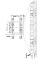
- the transmission of the PUCCH signal and DM-RS is assigned to one subframe every predetermined transmission period (in this example, a period obtained by multiplying the time length of the radio frame by a natural number). Further, for example, as shown in FIG. 4, the transmission of the PUCCH signal and the DM-RS is transmitted to RBs 901 to 908 at both ends in the direction along the frequency axis among a plurality of RBs included in the system bandwidth. Assigned.
- a DM-RS is allocated to each of two symbol periods (ST # 1 and ST # 5 in this example).
- the symbol period is a period corresponding to one RE.
- a PUCCH signal is assigned.
- the signal sequence cyclic shift parameter ⁇ is calculated based on a parameter determined for each terminal device 20.
- the plurality of signals that are respectively phase-rotated based on a plurality of different signal sequence cyclic shift parameters ⁇ are orthogonal to each other.
- the PUCCH signal and the DM-RS are received by the base station apparatus 10 as a code-multiplexed signal by being transmitted from each of the plurality of terminal apparatuses 20.
- the signals S-UE # 0 to # 2 respectively transmitted from the first to third terminal apparatuses 20 are received by the base station apparatus 10 as code-multiplexed signals. .
- the transmission of the PUCCH signal and the DM-RS is allocated to the RB associated with the PUCCH resource information n (2, p) PUCCH .
- the RB assigned to the transmission of the PUCCH signal and DM-RS is determined in advance in association with the parameter m.
- RBs associated with the same parameter m have different frequencies. In other words, frequency hopping is applied to radio resources allocated to PUCCH signals and DM-RS transmissions.
- N RB sc represents the number of subcarriers included in one RB.
- the transmission RF unit 213 executes transmission RF processing for converting the BB signal input from the channel multiplexing unit 212 into a radio signal.
- the transmission RF processing includes conversion from a digital signal to an analog signal and conversion from a base frequency to a radio frequency (in other words, up-conversion).
- the transmission RF unit 213 transmits a radio signal via the transmission antenna 214.
- the symbol parameter generation unit 205 the switching unit 206, the symbol parameter cyclic shift unit 207, and the signal sequence cyclic shift parameter calculation unit 208 will be described.
- the symbol parameter generation unit 205 acquires a cell identifier that identifies a cell in which the terminal device 20 is located. For example, the cell identifier is transmitted from the base station device 10 to the terminal device 20. The cell identifier may be acquired by the terminal device 20 based on information transmitted from the base station device 10 to the terminal device 20. The symbol parameter generation unit 205 generates a symbol parameter n cell cs (n) for each of a plurality of symbol periods included in the radio frame based on Expression 8.
- the symbol period number n represents a symbol period number.
- the symbol period number n is information for identifying a symbol period in each radio frame. In this example, the symbol period number starts from 0 and increases by 1 for each symbol period in the direction in which the time advances along the time axis in the radio frame.
- the symbol period number n is an example of identification information that identifies each of a plurality of periods included in a radio frame.
- the relationship between the symbol period number n and the symbol parameter n cell cs (n) represented by Expression 8 is an example of a third relationship.
- the symbol period number n represents each integer that is greater than or equal to 0 and smaller than N symb .
- N symb denotes (in other words, a symbol period number) number of symbol periods included in one radio frame.
- the number of symbol periods N sym is expressed by Equation 9.
- N UL symb represents the number of symbol periods included in one slot.
- N frame slot represents the number of slots included in one radio frame. In this example, the number of symbol periods N sym is 140.
- a plurality of respective symbols parameter n cell cs generated for symbol period included in the radio frame (0), ..., n cell cs (N symb -1) may be represented as symbol parameter sequence n cell cs .
- the symbol parameter generation unit 205 initializes the pseudo-random sequence c (x) based on the acquired cell identifier and Equation 6, as with the DM-RS generation unit 209. Therefore, in this example, the symbol parameter n cell cs (n) is determined based on the cell identifier that identifies the cell in which the terminal device 20 is located. Note that the symbol parameter generation unit 205 may share the pseudo-random sequence c (x) with the DM-RS generation unit 209.
- the symbol period number n may be expressed by Equation 10.
- l represents a symbol number.
- the symbol number is information for identifying a symbol period in each slot. In this example, the symbol number starts from 0 and increases by 1 for each symbol period in the direction in which the time advances along the time axis in the slot.
- Symbol parameter generating unit 205 outputs the generated symbol parameter sequence n cell cs to the switching unit 206. Based on the input setting information, the switching unit 206 transfers the symbol parameter sequence n cell cs input from the symbol parameter generation unit 205 to one of the symbol parameter cyclic shift unit 207 and the signal sequence cyclic shift parameter calculation unit 208. Is output.
- the setting information represents whether or not to perform symbol parameter cyclic shift described later.
- the setting information may be transmitted from the base station device 10 to the terminal device 20.
- the switching unit 206 outputs the symbol parameter sequence n cell cs to the symbol parameter cyclic shift unit 207 when the setting information indicates that the symbol parameter cyclic shift is executed.
- switching section 206 outputs symbol parameter sequence n cell cs to signal sequence cyclic shift parameter calculation section 208.
- the symbol parameter cyclic shift unit 207 acquires the frame number of the radio frame.
- the frame number may be expressed as SFN (System Frame Number).
- SFN System Frame Number
- the frame number is transmitted from the base station device 10 to the terminal device 20.
- the frame number may be acquired by the terminal device 20 based on information transmitted from the base station device 10 to the terminal device 20.
- the symbol parameter cyclic shift unit 207 is an example of an acquisition unit.
- the symbol parameter cyclic shift unit 207 cyclically shifts the symbol parameter series n cell cs input from the switching unit 206 by the shift amount ⁇ SFN (i) based on the acquired frame number i.
- i represents each integer from 0 to a predetermined maximum number.
- the maximum number is 1023, for example.
- the shift amount may be regarded as ⁇ SFN (i) mod N symb .
- the remainder calculated by the operator mod is a positive number.
- the cyclic shift of the symbol parameter series n cell cs may be expressed as a symbol parameter cyclic shift.
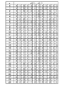
- the relationship between the shift amount ⁇ SFN (i) and the cyclically shifted symbol parameter sequence n ′ cell cs is expressed as shown in FIG.
- the symbol parameter cyclic shift unit 207 calculates the shift amount ⁇ SFN (i) based on Equation 12.
- the shift amount ⁇ SFN (i) is determined based on the relationship between the symbol period number n and the symbol parameter n cell cs (n) represented by Expression 8 and the acquired frame number i. Is done.
- the shift amount ⁇ SFN (i) is an example of a second shift amount.
- Symbol parameter cyclic shift section 207 outputs the cyclically shifted symbol parameter series n ′ cell cs to signal series cyclic shift parameter calculation section 208.
- the signal sequence cyclic shift parameter calculation unit 208 calculates a signal sequence cyclic shift parameter ⁇ (n).
- the signal sequence cyclic shift parameter ⁇ (n) is calculated based on the symbol parameter sequence n cell cs input from the switching unit 206 or the symbol parameter sequence n ′ cell cs input from the symbol parameter cyclic shift unit 207. It is.
- the signal sequence cyclic shift parameter calculation unit 208 calculates the signal sequence cyclic shift parameter ⁇ (n) based on Equation 13.
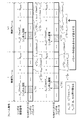
- the signal sequence cyclic shift parameter calculation unit 208 calculates the parameter n (p) cs (n) based on Equation 14.
- n ′ p (n s ) is a parameter determined based on the PUCCH resource information. Accordingly, the parameter n ′ p (n s ) is determined for each terminal device 20.
- the relationship between the symbol parameter n cell cs (n) and the signal sequence cyclic shift parameter ⁇ (n) represented by Equation 13 and Equation 14 is an example of a fourth relationship. Further, the relationship between the symbol period number n and the signal sequence cyclic shift parameter ⁇ (n) represented by Equation 8, Equation 13, and Equation 14 is an example of a first relationship.
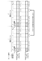
- the signal sequence cyclic shift parameter calculation unit 208 calculates the parameter n (p) cs (n) based on Equation 15.
- the relationship between the symbol period number n and the signal sequence cyclic shift parameter ⁇ (n) expressed by Equation 8, Equation 11 to Equation 13, and Equation 15 is an example of a second relationship.
- the signal sequence cyclic shift parameter calculation unit 208 outputs the calculated signal sequence cyclic shift parameter ⁇ (n) to the DM-RS generation unit 209 and the PUCCH generation unit 210, respectively.
- the DM-RS generation unit 209 includes a signal sequence cyclic shift parameter ⁇ (n) associated with a symbol period allocated to transmission of a DM-RS to be generated, of the input signal sequence cyclic shift parameter ⁇ (n). ) To generate the DM-RS.
- the PUCCH generation unit 210 is based on a signal sequence cyclic shift parameter ⁇ (n) associated with a symbol period allocated to transmission of a PUCCH signal scheduled to be generated among the input signal sequence cyclic shift parameters ⁇ (n). To generate the PUCCH signal.
- the DM-RS generated based on the signal sequence cyclic shift parameter ⁇ (n) calculated based on Expression 14 is an example of a signal sequence that is cyclically shifted without being based on the frame number.
- the DM-RS generated based on the signal sequence cyclic shift parameter ⁇ (n) calculated based on Equation 15 is an example of a signal sequence that is cyclically shifted based on the frame number.
- the symbol parameter n cell cs (n) generated by the symbol parameter generation unit 205 is used to calculate the signal sequence cyclic shift parameter ⁇ (n) for the symbol period number n. It is done.
- each terminal apparatus 20 calculates the signal sequence cyclic shift parameter ⁇ (n) using the symbol parameter n cell cs (n) common between radio frames for the same symbol period number n.
- the setting information represents performing symbol parameter cyclic shift
- the calculation of the signal sequence cyclic shift parameters for symbol period number n ⁇ (n) the symbol parameter was allowed to cyclic shift by the signal sequence cyclic shift parameter calculating unit 208 n 'cell cs (n) is used.
- the symbol parameter n ′ cell cs (n) used to calculate the signal sequence cyclic shift parameter ⁇ (n) is the symbol parameter n cell cs ⁇ (n ⁇ SFN (i)) mod N symb in the radio frame with frame number i. ⁇ .
- the symbol parameter n ′ cell cs (n) used for calculating the signal sequence cyclic shift parameter ⁇ (n) is the symbol parameter n cell cs ⁇ (n ⁇ ⁇ SFN (i + 1)) mod in the radio frame with frame number i + 1. N sym ⁇ .
- the symbol parameter n ′ cell cs (n) used for calculating the signal sequence cyclic shift parameter ⁇ (n) for the symbol period number n includes the radio frame with the frame number i, the radio frame with the frame number i + 1, Vary between.
- each terminal device 20 calculates the signal sequence cyclic shift parameter ⁇ (n) using the symbol parameter n ′ cell cs (n) that differs between radio frames for the same symbol period number n.
- the shift amount ⁇ SFN (i) has different values between cells for the same frame number i, as expressed in Expression 8 and Expression 12.
- the extent to which the DM-RSs transmitted by the first and second terminal devices 20 interfere with each other is likely to change with changes in the radio frame.
- the symbol parameter cyclic shift unit 207, the signal sequence cyclic shift parameter calculation unit 208, the DM-RS generation unit 209, the channel multiplexing unit 212, the transmission RF unit 213, and the transmission antenna 214 are examples of transmission units.
- the number of reception antennas 201 included in the terminal device 20 may be two or more. Further, the number of transmission antennas 214 included in the terminal device 20 may be two or more. Further, the terminal device 20 may include a shared antenna that functions as each of the reception antenna 201 and the transmission antenna 214 instead of the reception antenna 201 and the transmission antenna 214.
- the reception RF unit 202 and the transmission RF unit 213 may be realized using an LSI (Large Scale Integration).
- the LSI may be a programmable logic circuit device (for example, PLD or FPGA).
- PLD is an abbreviation for Programmable Logic Device.
- FPGA is an abbreviation for Field-Programmable Gate Array.
- the units 203 to 212 included in the terminal device 20 may be realized using a processing device and a storage device.
- the processing device may be a CPU (Central Processing Unit) or a DSP (Digital Signal Processor).
- the terminal device 30 has the same configuration as the terminal device 20 except that the terminal device 30 does not have a function of executing symbol parameter cyclic shift.
- the base station apparatus 10 includes a PUCCH resource allocation unit 101, a PDSCH generation unit 102, a CSI-RS generation unit 103, a channel multiplexing unit 104, a transmission RF unit 105, A transmission antenna 106.
- the base station apparatus 10 includes a symbol parameter generation unit 107, a switching unit 108, a symbol parameter cyclic shift unit 109, and a signal sequence cyclic shift parameter calculation unit 110.
- the base station apparatus 10 includes a reception antenna 111, a reception RF unit 112, a channel estimation unit 114, a frequency deviation estimation unit 115, a PUCCH demodulation unit 116, and a PUSCH demodulation unit 117.
- the PUCCH resource allocation unit 101 acquires terminal information.
- the terminal information includes a terminal identifier for identifying the terminal device 20 or 30, and information indicating whether the terminal device 20 or 30 can execute the symbol parameter cyclic shift.
- the terminal information is transmitted from the terminal device 20 or 30 to the base station device 10.
- the base station apparatus 10 may receive terminal information from an apparatus different from the terminal apparatuses 20 and 30 included in the wireless communication system 1.
- the PUCCH resource allocation unit 101 determines setting information and PUCCH resource information based on the acquired terminal information.
- Setting information indicating that symbol parameter cyclic shift is executed may be determined for the terminal device 20 that can execute symbol parameter cyclic shift.
- Setting information indicating that the symbol parameter cyclic shift is not executed is determined for the terminal device 30 that cannot execute the symbol parameter cyclic shift.
- the terminal device 20 for which the setting information indicating that the symbol parameter cyclic shift is executed may be represented as an execution terminal device.
- the terminal device 20 or 30 for which setting information indicating that symbol parameter cyclic shift is not performed may be represented as a non-execution terminal device.
- the PUCCH resource allocation unit 101 determines different PUCCH resource information for the execution terminal device 20 and the non-execution terminal device 20 or 30. Thereby, the PUCCH resource allocation unit 101 allocates different radio resources to DM-RS and PUCCH signal transmission by the execution terminal device 20 and the non-execution terminal device 20 or 30, respectively.
- PUCCH resource allocation unit 101 is an example of an allocation unit.
- PUCCH resource allocation section 101 outputs the determined PUCCH resource information and setting information to PDSCH generation section 102, switching section 108, signal sequence cyclic shift parameter calculation section 110, channel estimation section 114, and PUCCH demodulation section 116, respectively. To do.
- the PDSCH generating unit 102 generates a data signal transmitted via the PDSCH based on the PUCCH resource information and setting information input from the PUCCH resource allocating unit 101 and user data, and the generated data signal is used as a channel.
- the data is output to the multiplexing unit 104.
- user data is transmitted from information transmitted from a terminal device 20 or 30 different from the terminal device 20 or 30 to which the data signal is transmitted, or from a device different from the terminal devices 20 and 30 included in the wireless communication system 1.
- Information is transmitted from information transmitted from a terminal device 20 or 30 different from the terminal device 20 or 30 to which the data signal is transmitted, or from a device different from the terminal devices 20 and 30 included in the wireless communication system 1.
- CSI-RS generating section 103 generates CSI-RS and outputs the generated CSI-RS to channel multiplexing section 104.
- Channel multiplexing section 104 multiplexes signals input from PDSCH generation section 102 and CSI-RS generation section 103 and outputs the multiplexed signals to transmission RF section 105.
- the transmission RF unit 105 executes transmission RF processing for converting the BB signal input from the channel multiplexing unit 104 into a radio signal.
- the transmission RF unit 105 transmits a radio signal via the transmission antenna 106.
- the symbol parameter generation unit 107 functions in the same manner as the symbol parameter generation unit 205 except that the cell identifier held by the base station apparatus 10 is used.
- the switching unit 108 functions in the same manner as the switching unit 206 except that the setting information input from the PUCCH resource allocation unit 101 is used.
- the symbol parameter cyclic shift unit 109 functions in the same manner as the symbol parameter cyclic shift unit 207 except that the frame number held by the base station apparatus 10 is used.
- the symbol parameter cyclic shift unit 109 is an example of an acquisition unit.
- the signal sequence cyclic shift parameter calculation unit 110 uses the signal sequence cyclic shift parameter calculation unit 208, except that the PUCCH resource information input from the PUCCH resource allocation unit 101 is used and the output destination of the parameter ⁇ (n). Works in the same way.
- Signal sequence cyclic shift parameter calculation section 110 outputs signal sequence cyclic shift parameter ⁇ (n) to channel estimation section 114 and PUCCH demodulation section 116, respectively.
- the reception RF unit 112 performs reception RF processing for converting a radio signal received via the reception antenna 111 into a BB signal.
- Reception RF section 112 outputs the BB signal to channel estimation section 114, PUCCH demodulation section 116, and PUSCH demodulation section 117.
- the PUCCH demodulation unit 116 transmits via the PUCCH based on the input PUCCH resource information, the input signal sequence cyclic shift parameter ⁇ (n), and a channel estimation value and a frequency deviation estimation value, which will be described later. Demodulate the processed signal.
- the information obtained by demodulation includes CQI.
- the PUSCH demodulation unit 117 performs demodulation on a signal transmitted via the PUSCH among BB signals input from the reception RF unit 112 based on a frequency deviation estimation value described later.
- the information obtained by demodulation includes user data.
- the channel estimation unit 114 Based on the signal sequence cyclic shift parameter ⁇ (n) input from the signal sequence cyclic shift parameter calculation unit 110, the channel estimation unit 114 performs DM-RS (in other words, a replica signal) in the same manner as the DM-RS generation unit 209. ) Is generated.
- DM-RS in other words, a replica signal
- the channel estimation unit 114 is based on the generated replica signal and the signal transmitted using the radio resource allocated to the DM-RS transmission out of the BB signal input from the reception RF unit 112. Channel estimation.
- the signal used for channel estimation is a signal received in a radio frame having the frame number used for generating the replica signal.
- channel estimation is estimation of the state of a communication channel.
- the result of channel estimation may be expressed as a channel estimate.
- Channel estimation section 114 outputs the channel estimation value to each of frequency deviation estimation section 115 and PUCCH demodulation section 116.
- the frequency deviation estimation unit 115 estimates a frequency difference (in other words, a frequency deviation) between the base station device 10 and the terminal device 20 or 30 based on the channel estimation value input from the channel estimation unit 114.
- the frequency deviation may be expressed as a frequency difference.
- the result of the frequency deviation estimation may be expressed as a frequency deviation estimated value.
- Frequency deviation estimation section 115 outputs the frequency deviation estimation value to each of PUCCH demodulation section 116 and PUSCH demodulation section 117.
- the frequency deviation estimation unit 115 performs complex conjugate processing on the channel estimation value in one of the two symbol periods for each slot.
- h a, b (f) represents the channel estimation value for the f-th RE among the REs included in the slot with the slot number a and included in the symbol period with the symbol number b.
- f represents each integer that is greater than or equal to 0 and smaller than N RB sc .
- the channel estimation value in one of the two symbol periods in slot # 0 is represented by h 0,1 (0),..., H 0,1 (11).
- the channel estimate in one of the two symbol periods in slot # 1 is represented by h 1,1 (0),..., H 1,1 (11).
- the frequency deviation estimation unit 115 performs correlation calculation processing between the channel estimation value in the other of the two symbol periods and the channel estimation value after execution of the complex conjugate processing for each slot. .
- the channel estimation value in the other of the two symbol periods in slot # 0 is represented by h 0,5 (0),..., H 0,5 (11).
- the channel estimation value in the other of the two symbol periods in slot # 1 is represented by h 1,5 (0),..., H 1,5 (11).
- the frequency deviation estimation unit 115 performs an intra-frame averaging process on the result of the correlation calculation process for each of the two consecutive slots for each subframe.
- the intraframe averaging process includes a process of averaging the results of the correlation calculation process for each of the two slots.
- the intraframe average processing may include processing for averaging the results of the correlation calculation processing among the subcarriers.
- the frequency deviation estimation unit 115 performs an inter-frame averaging process on the result of the intra-frame averaging process for each of the plurality of subframes.
- the interframe averaging process includes a process of averaging the results of the intraframe averaging process for each of the plurality of subframes.
- the average may be a forgetting average.
- the forgetting average is expressed by Equation 16.
- ⁇ represents a forgetting factor.
- the forgetting factor ⁇ represents a real number larger than 0 and smaller than 1.
- R represents the result of the intraframe averaging process for a certain subframe.
- R ave represents the result of averaging process between frames.
- the frequency deviation estimator 115 updates the inter-frame average process result R ave based on Equation 16 every time the result of the intra-frame average process for the subframe is acquired.
- the average in the inter-frame averaging process may be a weighted average or an arithmetic average.
- the frequency deviation estimation unit 115 estimates the frequency deviation based on the result of the interframe averaging process.
- the frequency deviation estimation unit 115 holds the relationship between the value corresponding to the result of the inter-frame averaging process and the frequency deviation in advance, and holds the relationship and the result of the inter-frame averaging process. Based on this, the frequency deviation is estimated.
- Symbol parameter cyclic shift section 109 signal sequence cyclic shift parameter calculation section 110, DM-RS demodulation section 113, channel estimation section 114, and frequency deviation estimation section 115 are examples of estimation sections.
- the number of reception antennas 111 included in the base station apparatus 10 may be two or more.
- the number of transmission antennas 106 provided in the base station apparatus 10 may be two or more.
- the base station apparatus 10 may include a shared antenna that functions as each of the reception antenna 111 and the transmission antenna 106 instead of the reception antenna 111 and the transmission antenna 106.
- the reception RF unit 112 and the transmission RF unit 105 may be realized using an LSI.
- the units 101 to 103, 107 to 110, and 113 to 117 included in the base station device 10 may be realized using a processing device and a storage device.
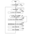
- the terminal device 20 when acquiring the SFN, the terminal device 20 makes a "Yes" determination, based on the acquired cell ID, and generates a symbol parameter n cell cs (n) for each of a plurality of symbol periods included in the radio frame (Step S103 in FIG. 10).
- the terminal device 20 determines whether or not the setting information represents performing symbol parameter cyclic shift (step S104 in FIG. 10).
- the setting information represents that symbol parameter cyclic shift is executed. Therefore, the terminal device 20 determines “Yes”, and executes a symbol parameter cyclic shift on the generated symbol parameter n cell cs (n) based on the acquired SFN (step S105 in FIG. 10).
- the terminal device 20 calculates the signal sequence cyclic shift parameter ⁇ (n) based on the symbol parameter n ′ cell cs (n) after execution of the symbol parameter cyclic shift (step S106 in FIG. 10).
- the terminal device 20 generates a DM-RS based on the calculated signal sequence cyclic shift parameter ⁇ (n) (step S107 in FIG. 10). Then, the terminal device 20 transmits the generated DM-RS in a radio frame having the acquired SFN (step S108 in FIG. 10). Thereafter, the terminal device 20 returns to step S102 in FIG. 10 and repeatedly executes the processing from step S102 to step S108. Note that the process of step S103 may be executed before the process of step S102. In addition, when the process of step S103 is repeatedly executed and the generated symbol parameter n cell cs (n) does not change, the process of step S103 may not be executed.
- the terminal apparatus 20 determines “No” in step S104, and does not execute the symbol parameter cyclic shift, and proceeds to step S106 in FIG. move on. In this case, the terminal device 20 calculates the signal sequence cyclic shift parameter ⁇ (n) based on the symbol parameter n cell cs (n) generated in step S103 (step S106 in FIG. 10).
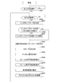
- the base station apparatus 10 executes the processing from step S201 to step S207 similar to the processing from step S101 to step S107 in FIG. 10.
- the base station apparatus 10 performs channel estimation based on the generated DM-RS (step S208 in FIG. 11).
- the base station apparatus 10 executes a correlation calculation process based on the channel estimation value, and executes an intra-frame averaging process for the result of the correlation calculation process (step S209 in FIG. 11).
- the base station apparatus 10 performs the inter-frame average process with respect to the result of the intra-frame average process (step S210 of FIG. 11).
- the base station apparatus 10 estimates the frequency deviation based on the result of the interframe averaging process (step S211 in FIG. 11). Then, the base station apparatus 10 performs demodulation with respect to the signal transmitted via PUCCH and PUSCH based on the frequency deviation estimated value (step S212 in FIG. 11). Thereafter, the base station apparatus 10 returns to step S202 in FIG. 11 and repeatedly executes the processing from step S202 to step S212.
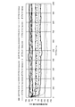
- FIG. 12 shows the change of the frequency deviation estimation value with respect to the subframe when the symbol parameter cyclic shift is not executed.
- the forgetting factor ⁇ is 0.9.
- the DM-RS and PUCCH used for PUCCH demodulation are allocated to radio resources at a period of 10 subframes. In other words, DM-RS and PUCCH used for demodulation of PUCCH are allocated to one subframe in one radio frame (having a time length of 10 ms in this example).
- the offset is the time difference between the head subframe in one radio frame and the subframe to which DM-RS is assigned in cell # 0 or cell # 1.
- the error of the frequency deviation estimated value tends to increase with respect to a specific offset.
- FIG. 13 shows a change C20 with respect to the subframe of the frequency deviation estimated value when the symbol parameter cyclic shift is executed.
- the first comparative example represents a change C21 with respect to the subframe of the frequency deviation estimated value when no interference wave exists.
- the second comparative example represents a change C22 with respect to the subframe of the frequency deviation estimated value when the symbol parameter cyclic shift is not performed. As shown in FIG. 13, the symbol parameter cyclic shift is executed, whereby the error of the frequency deviation estimated value can be suppressed.
- the terminal device 20 acquires the frame number of the radio frame. Furthermore, the terminal device 20 transmits a second signal sequence obtained by cyclically shifting the first signal sequence by the first shift amount based on the acquired frame number in a radio frame having the acquired frame number.
- the first shift amount can be changed based on the frame number. Therefore, the second signal sequence to be transmitted can be changed for each radio frame. As a result, it is possible to suppress the state in which the reception quality of the second signal sequence is excessively low from continuing. Therefore, the reception quality of the second signal sequence can be improved.
- the first shift amount is determined based on the second relationship and the identification information that identifies the period in which the second signal sequence is transmitted in the radio frame.
- the second relationship is a relationship in which the first relationship between the identification information for identifying each of the plurality of periods included in the radio frame and the shift amount is cyclically shifted by the second shift amount based on the frame number. is there.
- the first shift amount can be appropriately changed based on the frame number by appropriately changing the second shift amount based on the frame number.
- the first relationship includes a third relationship between the identification information and the parameter and a fourth relationship between the parameter and the shift amount. Further, the second shift amount is determined based on the frame number and the third relationship.
- the terminal device determines the second shift amount using a relationship different from the third relationship
- the terminal device must hold the relationship.
- the terminal device 20 does not have to hold a relationship different from the third relationship in order to determine the second shift amount. Therefore, the storage area used by the terminal device 20 can be reduced.
- the first relationship is determined based on an identifier that identifies a wireless area in which the second signal sequence is transmitted.
- the second signal sequences transmitted in parallel in the plurality of radio areas interfere with each other.
- the degree can be different for each radio frame. As a result, it is possible to suppress the state in which the reception quality of the second signal sequence is excessively low from continuing. Therefore, the reception quality of the second signal sequence can be improved.
- the base station apparatus 10 acquires the frame number of the radio frame. Furthermore, the base station apparatus 10 has received the second signal sequence obtained by cyclically shifting the first signal sequence by the first shift amount based on the acquired frame number and the radio frame having the acquired frame number. And channel estimation for a radio frame based on the signal.
- the first shift amount can be changed based on the frame number. Therefore, even if the cycle in which the second signal sequence is transmitted is a cycle obtained by multiplying the time length of the radio frame by a natural number, the second signal sequence to be transmitted can be changed for each radio frame. it can. As a result, it is possible to suppress the state in which the reception quality of the second signal sequence is excessively low from continuing. Therefore, the reception quality of the second signal sequence can be improved. As a result, the accuracy of channel estimation can be improved.
- the base station apparatus 10 uses different radio resources for transmission of signal sequences by the terminal apparatus 20 that performs symbol parameter cyclic shift and the terminal apparatus 20 or 30 that does not perform symbol parameter cyclic shift. Assigned to each.
- the signal sequence cyclic shift parameter ⁇ used to generate the signal sequence that is cyclically shifted based on the frame number and the signal sequence that is cyclically shifted not based on the frame number may be different from each other, It may be the same. Therefore, the signal sequence that is cyclically shifted based on the frame number and the signal sequence that is cyclically shifted not based on the frame number may not be orthogonal to each other.
- the two signal sequences when the two signal sequences are transmitted using the same radio resource, the two signal sequences may interfere with each other.
- the signal sequence that is cyclically shifted based on the frame number and the signal sequence that is cyclically shifted not based on the frame number are transmitted using different radio resources. The Therefore, the two signal sequences can be prevented from interfering with each other.
- the base station apparatus 10 includes a terminal apparatus 20 and a base station apparatus 10 that transmit a second signal sequence based on the result of channel estimation performed on each of a plurality of radio frames. Estimate the frequency difference between.
- Each of base station apparatus 10 and terminal apparatus 20 may cyclically shift symbol parameter series n cell cs based on Expression 17 instead of Expression 11.
- ⁇ represents an integer other than 0.
- each of the base station device 10 and the terminal device 20 may use the shift amount ⁇ SFN (i) instead of the shift amount ⁇ SFN (i) as the second shift amount.
- each of the base station apparatus 10 and the terminal apparatus 20 is configured to switch between a state in which symbol parameter cyclic shift is performed and a state in which symbol parameter cyclic shift is not performed.
- the terminal device 20 may be configured to have only a state in which symbol parameter cyclic shift is executed.
- the symbol parameter cyclic shift is performed on a signal transmitted from the terminal device 20 to the base station device 10 (in other words, an uplink signal).
- the object on which the symbol parameter cyclic shift is performed may be a signal (in other words, a downlink signal) transmitted from the base station apparatus 10 to the terminal apparatus 20.
- the object on which the symbol parameter cyclic shift is executed is DM-RS.
- the target on which the symbol parameter cyclic shift is executed may be a reference signal different from that of the DM-RS.
- the target on which the symbol parameter cyclic shift is executed may be a reference signal used for demodulation of a data signal, or may be a reference signal used for demodulation of both a data signal and a control signal.
- the object on which the symbol parameter cyclic shift is performed may be a signal different from the reference signal.
- radio communication system 10 base station apparatus 101 PUCCH resource allocation unit 102 PDSCH generation unit 103 CSI-RS generation unit 104 channel multiplexing unit 105 transmission RF unit 106 transmission antenna 107 symbol parameter generation unit 108 switching unit 109 symbol parameter cyclic shift unit 110 signal Sequence cyclic shift parameter calculation unit 111 Reception antenna 112 Reception RF unit 114 Channel estimation unit 115 Frequency deviation estimation unit 116 PUCCH demodulation unit 117 PUSCH demodulation unit 20 Terminal device 201 Reception antenna 202 Reception RF unit 203 PDSCH demodulation unit 204 CQI calculation unit 205 Symbol Parameter generation unit 206 Switching unit 207 Symbol parameter cyclic shift unit 208 Signal sequence cyclic shift parameter calculation unit 209 DM-RS generation unit 210 PUCCH raw Part 211 PUSCH generation unit 212 channel multiplexing unit 213 transmission RF unit 214 transmitting antenna 30 terminal NW network
Landscapes
- Engineering & Computer Science (AREA)
- Computer Networks & Wireless Communication (AREA)
- Signal Processing (AREA)
- Mobile Radio Communication Systems (AREA)
Abstract
L'invention concerne un appareil d'émission (20) qui émet des signaux par radio. L'appareil d'émission (20) comprend une unité d'acquisition (207) et une unité d'émission (207). L'unité d'acquisition (207) acquiert le numéro de trame d'une trame radio. L'unité d'émission (207, 208, 209, 212, 213, 214) émet, dans la trame radio ayant le numéro de trame acquise, une seconde séquence de signal obtenue par décalage cyclique d'une première séquence de signaux par une première quantité de décalage sur la base du numéro de trame acquise.
Priority Applications (1)
| Application Number | Priority Date | Filing Date | Title |
|---|---|---|---|
| PCT/JP2015/070654 WO2017013728A1 (fr) | 2015-07-21 | 2015-07-21 | Appareil d'émission, appareil de réception, système de communication par radio, et procédé de traitement |
Applications Claiming Priority (1)
| Application Number | Priority Date | Filing Date | Title |
|---|---|---|---|
| PCT/JP2015/070654 WO2017013728A1 (fr) | 2015-07-21 | 2015-07-21 | Appareil d'émission, appareil de réception, système de communication par radio, et procédé de traitement |
Publications (1)
| Publication Number | Publication Date |
|---|---|
| WO2017013728A1 true WO2017013728A1 (fr) | 2017-01-26 |
Family
ID=57834086
Family Applications (1)
| Application Number | Title | Priority Date | Filing Date |
|---|---|---|---|
| PCT/JP2015/070654 Ceased WO2017013728A1 (fr) | 2015-07-21 | 2015-07-21 | Appareil d'émission, appareil de réception, système de communication par radio, et procédé de traitement |
Country Status (1)
| Country | Link |
|---|---|
| WO (1) | WO2017013728A1 (fr) |
Cited By (1)
| Publication number | Priority date | Publication date | Assignee | Title |
|---|---|---|---|---|
| CN115529110A (zh) * | 2022-09-30 | 2022-12-27 | 潍柴动力股份有限公司 | 数据处理方法及装置 |
Citations (3)
| Publication number | Priority date | Publication date | Assignee | Title |
|---|---|---|---|---|
| JP2009535936A (ja) * | 2006-04-27 | 2009-10-01 | テキサス インスツルメンツ インコーポレイテッド | 無線通信システムにおいて基準信号を割り当てるための方法及び装置 |
| JP2013517675A (ja) * | 2010-01-18 | 2013-05-16 | テレフオンアクチーボラゲット エル エム エリクソン(パブル) | 無線基地局及びユーザ装置、並びにそれらにおける方法 |
| JP2013522948A (ja) * | 2010-03-11 | 2013-06-13 | エルジー エレクトロニクス インコーポレイティド | 制御チャネルの割当方法及びそのための装置 |
-
2015
- 2015-07-21 WO PCT/JP2015/070654 patent/WO2017013728A1/fr not_active Ceased
Patent Citations (3)
| Publication number | Priority date | Publication date | Assignee | Title |
|---|---|---|---|---|
| JP2009535936A (ja) * | 2006-04-27 | 2009-10-01 | テキサス インスツルメンツ インコーポレイテッド | 無線通信システムにおいて基準信号を割り当てるための方法及び装置 |
| JP2013517675A (ja) * | 2010-01-18 | 2013-05-16 | テレフオンアクチーボラゲット エル エム エリクソン(パブル) | 無線基地局及びユーザ装置、並びにそれらにおける方法 |
| JP2013522948A (ja) * | 2010-03-11 | 2013-06-13 | エルジー エレクトロニクス インコーポレイティド | 制御チャネルの割当方法及びそのための装置 |
Cited By (1)
| Publication number | Priority date | Publication date | Assignee | Title |
|---|---|---|---|---|
| CN115529110A (zh) * | 2022-09-30 | 2022-12-27 | 潍柴动力股份有限公司 | 数据处理方法及装置 |
Similar Documents
| Publication | Publication Date | Title |
|---|---|---|
| EP3606219B1 (fr) | Procédé, appareil et système de transmission de signal de référence | |
| JP6078078B2 (ja) | 無線・ネットワークにおける基準信号生成の初期設定 | |
| JP6095778B2 (ja) | チャネル推定のための地理的に同一なアンテナポート | |
| JP4808260B2 (ja) | 無線通信方法及び基地局並びにユーザ端末 | |
| CN106797649B (zh) | 与灵活的csi配置和关联反馈有关的系统和方法 | |
| US9048912B2 (en) | Mobile terminal apparatus, radio base station apparatus and communication control method | |
| JP6081080B2 (ja) | 無線通信システム、基地局装置、ユーザ端末、及び無線通信方法 | |
| JP5695034B2 (ja) | 送信装置、受信装置、送信方法、及び通知方法 | |
| CN112491769B (zh) | 上行参考信号 | |
| JP6721127B2 (ja) | ユーザ機器、基地局、ユーザ機器の方法、及び基地局の方法 | |
| JP5970061B2 (ja) | 端末装置、無線送信方法、基地局装置およびチャネル推定方法 | |
| JP5893999B2 (ja) | 無線通信システム、基地局装置、ユーザ端末、及び無線通信方法 | |
| JP2011518461A (ja) | 通信システムにおける隣接セル品質測定 | |
| WO2011098037A1 (fr) | Procédé permettant de générer un signal de référence, station de base et terminal | |
| KR20120135293A (ko) | 업링크 사운딩 참조 신호를 전송하는 방법, 채널을 추정하는 방법, 이동 단말, 기지국 및 무선 통신 시스템 | |
| JP2015207816A (ja) | 受信装置、受信方法、及び、無線通信システム | |
| CN105191246A (zh) | 通过频域中的基本序列的圆旋转对参考信号提供正交性 | |
| JP6296167B2 (ja) | 通信システムおよび通信方法 | |
| WO2017013728A1 (fr) | Appareil d'émission, appareil de réception, système de communication par radio, et procédé de traitement | |
| JP7215634B2 (ja) | ユーザ機器、及び基地局 | |
| JP2016039381A (ja) | 受信装置、受信方法、及び、無線通信システム | |
| JP5397427B2 (ja) | 無線通信方法及び無線通信システム並びにユーザ端末 | |
| JP6398612B2 (ja) | 基地局及びセル選択方法 | |
| JP2023036960A (ja) | ユーザ機器、及び基地局 | |
| JP2016139858A (ja) | 推定装置、制御方法、及びプログラム |
Legal Events
| Date | Code | Title | Description |
|---|---|---|---|
| 121 | Ep: the epo has been informed by wipo that ep was designated in this application |
Ref document number: 15898888 Country of ref document: EP Kind code of ref document: A1 |
|
| NENP | Non-entry into the national phase |
Ref country code: DE |
|
| 122 | Ep: pct application non-entry in european phase |
Ref document number: 15898888 Country of ref document: EP Kind code of ref document: A1 |
|
| NENP | Non-entry into the national phase |
Ref country code: JP |