WO2017013760A1 - Dispositif de communication sans fil, système de détection de présence, procédé et programme - Google Patents
Dispositif de communication sans fil, système de détection de présence, procédé et programme Download PDFInfo
- Publication number
- WO2017013760A1 WO2017013760A1 PCT/JP2015/070795 JP2015070795W WO2017013760A1 WO 2017013760 A1 WO2017013760 A1 WO 2017013760A1 JP 2015070795 W JP2015070795 W JP 2015070795W WO 2017013760 A1 WO2017013760 A1 WO 2017013760A1
- Authority
- WO
- WIPO (PCT)
- Prior art keywords
- person
- space
- detection signal
- situation
- state
- Prior art date
- Legal status (The legal status is an assumption and is not a legal conclusion. Google has not performed a legal analysis and makes no representation as to the accuracy of the status listed.)
- Ceased
Links
Images


Classifications
-
- G—PHYSICS
- G08—SIGNALLING
- G08B—SIGNALLING SYSTEMS, e.g. PERSONAL CALLING SYSTEMS; ORDER TELEGRAPHS; ALARM SYSTEMS
- G08B21/00—Alarms responsive to a single specified undesired or abnormal condition and not otherwise provided for
- G08B21/02—Alarms for ensuring the safety of persons
- G08B21/04—Alarms for ensuring the safety of persons responsive to non-activity, e.g. of elderly persons
-
- G—PHYSICS
- G08—SIGNALLING
- G08B—SIGNALLING SYSTEMS, e.g. PERSONAL CALLING SYSTEMS; ORDER TELEGRAPHS; ALARM SYSTEMS
- G08B21/00—Alarms responsive to a single specified undesired or abnormal condition and not otherwise provided for
- G08B21/18—Status alarms
- G08B21/22—Status alarms responsive to presence or absence of persons
Definitions
- the present invention relates to a wireless communication device, a presence detection system, a method, and a program.
- a presence detection system that detects the presence of a person using the principle that the received signal strength of radio waves (detection signals) in a multipath environment in the space varies depending on the movement of the person in the space. Proposed.
- Patent Document 1 discloses a system that uses a TV broadcast radio wave as a detection signal and detects whether or not a person is present in an indoor space based on fluctuations in the radio wave reception level in a multipath environment.
- Patent Document 2 discloses that it is determined whether or not the amount of change in the intensity of the radio wave output by the wireless access point exceeds a threshold value in order to detect the presence / absence of an abnormality in the dweller in the residence.
- Patent Document 3 discloses a system that detects the number of people in a room based on the standard deviation of the received signal strength of a radio signal in order to appropriately control the air conditioner.
- the number of detection signal transmissions may be increased, that is, the time interval for outputting a radio signal may be shortened.
- the power consumption of the transmitter and the receiver is increased.
- Patent Document 4 describes that when a person is absent, the radio signal reception level is used as a reference value, and when the radio signal reception level changes from the reference value, the radio signal transmission / reception interval is shortened.
- Patent Document 5 describes that, in an intermittent reception method in which a reception state and a non-reception state are intermittently repeated, transition to a reception state is triggered by receiving a start signal a plurality of times.
- JP 2006-212213 A International Publication No. 2009/125627 JP 2010-54098 A International Publication No. 2012/137285 JP 10-155187 A
- the conventional presence detection system detects only whether or not there is a person in the space to be detected. For this reason, when there is a person in the space, a single control relating to reduction of power consumption is performed for devices (transmitter, receiver, etc.) for presence detection regardless of the human activity state. For example, when there is almost no movement of a person in the space, such as a person sitting still on a chair, there is almost no change in the propagation path of the detection signal. Therefore, the reception level of the detection signal is stabilized. For example, when a person in the space is moving, such as a person walking around in the space, the propagation path of the detection signal is blocked by the person, and the detection signal is reflected by the person. Therefore, the reception level of the detection signal is not stable. In other words, the multipath propagation environment changes according to the activity state of the person in the space. For this reason, when a single control is performed when there is a person in the space, it is not possible to perform appropriate control regarding reduction of power consumption.
- the present invention has been made to solve the above-described problems, and determines whether or not there is a person in the space to be detected, and if there is a person, the activity state of the person is determined.
- An object of the present invention is to reduce the power consumption of a device for presence detection by increasing or decreasing the communication frequency of the detection signal based on the result.
- the wireless communication apparatus is a wireless communication apparatus that communicates with a transmitter that transmits a detection signal for detecting the presence or absence of a person.
- the acquisition unit acquires a variation in signal intensity of the detection signal received within a predetermined period.
- the discriminating means is based on the first situation where there is no person in the space based on the variation, the second situation where the person is present in the space and the person's activity state is the first state, It is determined which of the three situations, the third situation where the person is present and the person's activity state is the second state, is the spatial situation.
- the instructing means instructs the transmitter to change the time interval of transmission of the detection signal when the result determined by the determining means is different from the result determined by the determining means last time.
- the time interval of transmission of the detection signal is controlled according to the activity state of the person, and the power consumption of the device related to communication of the detection signal is reduced. be able to.
- FIG. 10 is a sequence diagram showing a series of processes related to air conditioning control of the presence detection system according to Embodiment 2.
- the presence detection system 1000 uses a wireless communication function of a device in the detection target space to determine whether or not a person exists in the detection target space and, if there is a person, the activity state of the person. Determine. Further, the presence detection system 1000 controls the frequency of detection signal communication according to the presence / absence of a person and the activity state of the person.
- the presence detection system 1000 includes a wireless sensor terminal 100 that outputs (sends) a detection signal, and a control device 200 that receives the detection signal and determines the presence / absence of a person and the activity state of the person.
- the control device 200 is a centralized controller that centrally manages equipment.
- the control device 200 centrally manages the air conditioner 300 connected by the dedicated line 2.
- the air conditioner 300 includes an indoor unit 301 and an outdoor unit 302 that cooperate to provide an air conditioning function.
- the wireless sensor terminal 100, the control device 200, and the indoor unit 301 of the air conditioner 300 are installed in the room 1.
- the outdoor unit 302 of the air conditioner 300 is installed outdoors, that is, outside the room 1.
- the wireless sensor terminal 100 serves as a transmitter that outputs (sends) a detection signal. For this reason, the wireless sensor terminal 100 is required to output a wireless signal having a predetermined output level or higher.
- the wireless sensor terminal 100 does not need to be fixed to the wall or the like of the room 1, but it is necessary that the position of the wireless sensor terminal 100 does not change at least for a predetermined period.
- the wireless sensor terminal 100 is, for example, a PC (Personal Computer) existing in the room 1, a wireless LAN access point, a wireless LAN router having a wireless LAN access point function, or a remote controller of the air conditioner 300 provided in the room 1. .
- PC Personal Computer
- the configuration of the wireless sensor terminal 100 will be described. Note that the configuration related to communication of detection signals will be mainly described.
- the wireless sensor terminal 100 controls the communication unit 110 that communicates with other devices, a program necessary for the operation of the wireless sensor terminal 100, a storage unit 120 that stores data, a sensor unit 130 that includes various sensors, and the wireless sensor terminal 100 as a whole. Control unit 140. Each part of the wireless sensor terminal 100 is connected by a bus 160.
- the communication unit 110 performs wireless communication with other devices under the control of the control unit 140.
- the communication unit 110 includes an antenna 111 and a wireless communication circuit 112.
- the wireless communication circuit 112 includes a modulation / demodulation circuit, a band limiting filter, and an amplifier.
- the wireless communication circuit 112 performs modulation processing, band limitation processing, signal amplification processing, and the like, and outputs a wireless signal to the antenna 111. Accordingly, a radio wave having a frequency determined from the antenna 111 is output.
- the radio communication circuit 112 demodulates the radio signal by band limiting processing, demodulation processing, and the like, and outputs a demodulated signal (information signal) to the control unit 140.
- the communication unit 110 transmits a detection signal to the control device 200 by wireless communication.
- the detection signal output from the communication unit 110 conforms to standards such as WiFi (registered trademark), 920 MHz, and 400 MHz extra-small communication.
- the detection signal may be a beacon signal or a predetermined communication signal.
- the radio wave output from the antenna 111 is repeatedly reflected, diffracted, and transmitted by the ceiling or floor of the room 1 or the fixtures arranged, and reaches the control device 200. Therefore, the control device 200 receives a multipath radio signal as the detection signal.
- the wireless sensor terminal 100 when a person is carrying the wireless sensor terminal 100, the wireless sensor terminal 100 cannot be used as a transmitter.
- the control unit 140 detects that the wireless sensor terminal 100 is not stationary by an acceleration sensor or an angular velocity sensor built in the wireless sensor terminal 100, the control unit 140 does not cause the communication unit 110 to output a detection signal.
- the communication unit 110 transmits measured values regarding the environment of the room 1 including the room temperature, the room humidity, and the like acquired by the sensor unit 130 to the control device 200 by wireless communication.
- the storage unit 120 includes a RAM (Random Access Memory), a ROM (Read Only Memory), a flash memory, and the like.
- the storage unit 120 stores an OS 121 that controls the wireless sensor terminal 100 as a whole, a transmission program 122 related to transmission of a detection signal, and a transmission interval parameter 123 that indicates the transmission interval of the detection signal.
- the sensor unit 130 includes a temperature sensor, a humidity sensor, an illuminance sensor, a carbon dioxide concentration sensor, a distance sensor, and a human sensor.
- the carbon dioxide concentration sensor measures the carbon dioxide concentration in the room 1.
- the distance sensor measures the distance from the wireless sensor terminal 100 to a person or the like in the room 1.
- the human sensor detects the location of a person in the room 1.
- Each sensor of the sensor unit 130 performs measurement at a predetermined time interval.
- the control unit 140 includes a processor such as a CPU (Central Processing Unit), a work memory, and a timing device.
- the control unit 140 executes the OS 121 stored in the storage unit 120 and controls the wireless sensor terminal 100 as a whole. Further, the control unit 140 executes the transmission program 122 stored in the storage unit 120 and causes the communication unit 210 to output a detection signal at every time specified by the transmission interval parameter 123.
- the control unit 140 further updates the value of the transmission interval parameter 123 when instructed by the control device 200 to change the transmission frequency of transmission of the detection signal.
- the control device 200 is a receiver that receives a detection signal.
- the control device 200 receives the detection signal, and determines whether or not there is a person in the room 1 based on the detection signal, and if so, the activity state of the person. Furthermore, the control device 200 instructs the wireless sensor terminal 100 to change the transmission frequency of the detection signal. Furthermore, the control device 200 centrally manages the air conditioner 300.
- the configuration of the control device 200 will be described. Note that the description will focus on the configuration related to communication of detection signals and control of the wireless sensor terminal 100.
- the control device 200 is required for the operation of the communication unit 210 that communicates with other devices, the storage unit 220 that stores programs and data necessary for the operation of the control device 200, the input / output unit 230 including an input / output interface, and the control device 200. And a control unit 240 that controls the entire control device 200. Each part of the control device 200 is connected by a bus 260.
- the communication unit 210 performs wireless communication with other devices under the control of the control unit 240.
- the communication unit 210 includes an antenna 211, a wireless communication circuit 212, and a wired communication circuit 213.
- the wireless communication circuit 212 includes a modulation / demodulation circuit, a band limiting filter, and an amplifier.
- the wireless communication circuit 212 performs band limiting processing, demodulation processing, signal amplification processing, and the like, and outputs a demodulated signal (information signal) to the control unit 240.
- the wireless communication circuit 212 performs modulation processing, band limitation processing, signal amplification processing, and the like, and outputs a wireless signal to the antenna 211.
- the wired communication circuit 213 performs wired communication with the air conditioner 300 via the dedicated line 2.
- the control device 200 and the air conditioner 300 exchange control signals regarding the operation of the air conditioner 300 with each other.
- the storage unit 220 includes a RAM, a ROM, a flash memory, and the like.
- the storage unit 220 stores an OS 221 that controls the entire control apparatus 200 and a determination program 222 for determining the presence / absence of a person in the room 1 and the activity state of the person based on the detection signal.
- the storage unit 220 stores a threshold value table 223 for storing threshold values for determining the presence / absence of a person and a person's activity state, and the result of determining the presence / absence of a person and the activity state of a person.
- the determination history 224 includes an instruction table 225 in which instructions relating to the transmission time intervals of detection signals (hereinafter referred to as transmission intervals) are defined. Details of the threshold value table 223 and the instruction table 225 will be described later.
- the input / output unit 230 is a user interface and includes an input device such as a button and a touch panel, and an output device such as a display and a speaker. For example, when the button operation is detected, the input / output unit 230 outputs an operation signal corresponding to the button operation to the control unit 240. The input / output 230 displays an image based on the image signal supplied from the control unit 240 on the display.
- the control unit 240 includes a processor such as a CPU, a work memory, and a timing device. Further, the control unit 240 includes means for measuring the received signal strength of the detection signal (received signal strength measuring circuit or the like). The control unit 240 executes the OS 221 stored in the storage unit 220 and controls the entire control device 200. The control unit 240 executes the determination program 222 and functions as the acquisition unit 241, the determination unit 242, and the instruction unit 243 illustrated in FIG.
- the acquisition unit 241 measures the received signal strength (RSSI) of the detection signal received by the communication unit 210 during a certain period (for example, 30 seconds). Furthermore, the acquisition unit 241 obtains the standard deviation of RSSI from the measured value of RSSI measured during a certain period.
- RSSI received signal strength
- the discriminating unit 242 discriminates whether or not there is a person in the room 1 based on the RSSI standard deviation obtained by the obtaining unit 241 and, if there is a person, the activity state of the person. Further, the determination unit 242 compares the previous determination result with the current determination result to determine whether or not the state of the room 1 has changed.
- the instruction unit 243 instructs the wireless sensor terminal 100 to change the detection signal transmission interval.
- the radio wave reception level (reception signal strength) in the control device 200 is substantially constant, that is, is stable.
- the propagation path is interrupted or the radio wave is reflected by the person.
- the received signal strength of the detection signal decreases or increases, that is, fluctuates.
- the operation of the person in the room 1 also affects the fluctuation of the received signal strength of the detection signal. For example, when a person is walking in the space to be detected, the received signal strength varies in the range of 10 dB to 15 dB in a few seconds.
- the amount of fluctuation in the received signal intensity is not large compared to when the person is walking. This is because the position of the person and the positions of the person's arms and legs are almost unchanged. In other words, the multipath propagation environment changes depending on the amount of human activity existing in the space to be detected.
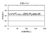
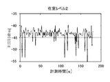
- the relationship between the state of the space to be detected (the presence / absence of a person, the person's activity state) and the received signal strength of the detection signal was investigated.
- a RSSI having a configuration similar to that of the wireless sensor terminal 100 and a receiver having a configuration similar to that of the control device 200 are used in a room having the same conditions as the room 1, and the RSSI is used.
- the transmitter continuously transmitted detection signals at a determined frequency.
- FIG. 3A shows a graph of RSSI measured in the absence.
- FIG. 3B shows a graph of RSSI measured in the case of occupancy level 1.
- FIG. 3C shows a graph of RSSI measured in the case of occupancy level 2.
- the graphs of FIGS. 3A to 3C are graphs of RSSI values measured by the receiver at predetermined time intervals.
- RSSI hardly fluctuates as shown in FIG. 3A.
- occupancy level 1 As shown in FIG. 3B, the range of fluctuation of RSSI is larger than in the case of absence.
- the RSSI fluctuation amount is the largest among the three conditions.
- RSSI variation was obtained for each of the three conditions.
- standard deviation was used as an index representing variation.
- the fixed period about 180 seconds was divided into periods of 30 seconds, and the standard deviation of RSSI (RSSI standard deviation) measured in each period was obtained.
- FIG. 4 shows a graph of the RSSI standard deviation.
- the variation in RSSI is the smallest in the absence, and the largest in the occupancy level 2.
- the variation in RSSI at the occupancy level 1 is larger than that at the absence, and smaller than that at the occupancy level 2.
- the ranges that can be taken by the standard deviation of RSSI of each of the three conditions are different and do not overlap each other. From this, absence, occupancy level 1, occupancy level 2 between each possible range (boundary) value as a threshold, by comparing the standard deviation of the RSSI of the detection signal and the threshold, Whether the occupancy level is 1 or the occupancy level 2 can be determined. For this reason, the value between the range that can be taken by the standard deviation of the absent RSSI and the range that can be taken by the standard deviation of the RSSI at the occupancy level 1 was set as the threshold value 1. The value between the range in which the standard deviation of RSSI at the occupancy level 1 can be taken and the range in which the standard deviation of RSSI at the occupancy level 2 can take was set as the threshold 2.
- the standard deviation of RSSI in the absence was within the range of 0.06 to 0.2 dB.
- the standard deviation of RSSI in the case of occupancy level 1 was in the range of 0.5 to 0.8 dB.
- the standard deviation of RSSI in the case of occupancy level 2 was in the range of 1.3 dB to 4.2 dB. Therefore, the threshold for distinguishing absence and occupancy level 1 (hereinafter referred to as threshold 1) was set to 0.3 dB, and the threshold for distinguishing between occupancy level 1 and occupancy level 2 (hereinafter referred to as threshold 2) was set to 1.0 dB.
- Threshold value 1 and threshold value 2 obtained prior to processing related to transmission interval control of the wireless sensor terminal 100 described later are stored in the threshold value table 223 of the control device 200. An example of data stored in the threshold table 223 is shown in FIG.
- Threshold value 1 and threshold value 2 are determined by the following method, for example. First, the detection signal is transmitted and received in the room 1 or in the same room as the room 1, and the RSSI is measured. Then, the standard deviation of RSSI is obtained from the measured value of RSSI, and threshold values 1 and 2 are obtained from the standard deviation of RSSI. Alternatively, the RSSI standard deviation, threshold value 1, and threshold value 2 are obtained by simulation using a computer. In the test and simulation for obtaining the threshold values 1 and 2, it is necessary to set the conditions of the space, the transmitter, the receiver, and the like to the same conditions as the conditions for actually measuring the detection signal.
- the control device 200 measures the RSSI of the received detection signal and obtains the RSSI standard deviation. Then, the control device 200 compares the RSSI standard deviation with the threshold value 1 and the threshold value 2 of the threshold value table 223 to determine the state of the room 1. When the state of the room 1 determined based on the threshold value 1 and the threshold value 2 is different from the previous determination result, the control device 200 transmits a control signal instructing the wireless sensor terminal 100 to change the detection signal transmission interval.
- the content of the instruction transmitted from the control device 200 to the wireless sensor terminal 100 is defined in the instruction table 225.
- FIG. 6 shows an example of data stored in the instruction table 225.
- the transmission interval at occupancy level 2 is the default. If the amount of fluctuation in the propagation path is expected to be small, such as changing from occupancy level 1 or occupancy level 2 to absence, or changing from occupancy level 2 to occupancy level 1, send Instructing to increase the interval is defined. In addition, when the amount of fluctuation in the propagation path is expected to increase, such as a change from absence to occupancy level 1 or occupancy level 2 or change from occupancy level 1 to occupancy level 2. Instructing to shorten the transmission interval is defined.
- threshold values 1 and 2 are obtained in advance and stored in the threshold value table 223 of the storage unit 220 of the control device 200.
- a default value (1 second) is set in the transmission interval parameter 123 of the storage unit 120 of the wireless sensor terminal 100.
- the default value is the transmission interval of the detection signal when the state of the room 1 is the occupancy level 2.
- the control unit 140 executes the transmission program 122 and performs the following processing.
- the control unit 140 causes the communication unit 110 to output a detection signal every time (one second) specified in the transmission interval parameter 123. Therefore, the radio wave (detection signal) output from the antenna 111 of the wireless sensor terminal 100 is repeatedly reflected, diffracted, and transmitted by the ceiling or floor of the room 1 and reaches the control device 200.
- control device 200 At the same time as the wireless sensor terminal 100 is turned on, the control device 200 is also turned on.
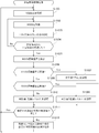
- the control unit 240 executes the determination program 222 and executes a series of processes shown in FIG.
- the control unit 240 stores the current time in the storage unit 220 as the start time (step S1001).
- the control unit 240 acquires the RSSI of the detection signal (step S1002). Specifically, the detection signal received by the antenna 211 is input to the control unit 240 via the wireless communication circuit 212.
- the control unit 240 measures the RSSI of the detection signal using a signal strength measurement circuit or the like, and stores the RSSI measurement value in the storage unit 220.
- the control unit 240 puts a wait for one cycle (one second) (step S1003). That is, it waits for 1 second.
- the control unit 240 determines whether or not a certain time (30 seconds) has elapsed from the start time (step S1004). When a certain time (30 seconds) has elapsed from the start time (step S1004; Yes), the control unit 240 calculates the RSSI standard deviation X from the RSSI acquired in the past 30 seconds (step S1005).
- the RSSI standard deviation X is stored in the storage unit 220 together with the current time.
- the control unit 240 compares the RSSI standard deviation X with the threshold 1 (step S1006). When the control unit 240 determines that the RSSI standard deviation X is equal to or less than the threshold 1 (step S1006; Yes), the control unit 240 determines that the state of the room 1 is absent, and stores the determination value “absence” in the determination history 224 together with the time. (Step S1007). On the other hand, if the control part 240 discriminate
- the control unit 240 determines that the state of the room 1 is the occupancy level 1, and sets the determination value “occupancy level 1” as the time. At the same time, it is stored in the discrimination history 224 (step S1009).
- the control unit 240 determines that the state of the room 1 is the occupancy level 2, and sets the determination value “occupancy level 2”.
- the determination history 224 is stored together with the time (step S1010).
- control unit 240 determines whether or not the previous determination value is the same as the current determination value (step S1011). Specifically, the control unit 240 reads, from the determination history 224 of the storage unit 220, the determination value stored with the time closest to the current time and the determination value stored with the time closest to the current time. Compare discriminant values. When the previous discriminant value and the current discriminant value are the same (step S1011; Yes), the control unit 240 deletes the RSSI measurement value stored in the storage unit 220 for 30 seconds, and then performs the process of step S1001 again. Return.
- the control unit 240 instructs the wireless sensor terminal 100 to change the time interval of transmission of the detection signal (step S1012). Specifically, the control unit 240 acquires an instruction to be transmitted to the wireless sensor terminal 100 from the instruction table 225 illustrated in FIG. 6 based on the previous determination value and the current determination value. The control unit 240 transmits a control signal indicating an instruction to the wireless sensor terminal 100 via the communication unit 210. For example, when the previous discriminant value is “in-room level 2” and the current discriminant value is “in-room level 1”, the control unit 240 indicates an instruction “change the transmission interval to 3 seconds”. A control signal is transmitted to the wireless sensor terminal 100. Thereafter, the control unit 240 deletes the RSSI measurement value stored in the storage unit 220 for 30 seconds, and then returns to the process of step S1001 again.
- the wireless sensor terminal 100 changes the value of the transmission interval parameter 123 of the storage unit 120 from the current default value to 3 seconds when receiving the control signal instructing the change of the transmission interval from the control device 200.
- the above is the transmission interval control processing according to the first embodiment.
- a multipath propagation environment that varies depending on the amount of human activity is considered.
- the wireless sensor terminal 100 outputs a detection signal at a transmission frequency according to a multipath propagation environment assumed by the state of the room 1. For this reason, the wireless sensor terminal 100 does not transmit a detection signal unnecessarily. Therefore, the power consumption of the wireless sensor terminal 100 can be reduced.
- the presence detection system 1000 can be easily and further reduced in cost. Can be built.
- the control device 200 discriminates (senses) the state of the room 1 and controls the transmission frequency of the detection signal based on the discrimination result. However, not only the control of the transmission frequency of the detection signal, but also the control device 200 can perform other controls using the determination result for the room 1.
- Each sensor of the sensor unit 130 of the wireless sensor terminal 100 performs measurement at a time interval defined in the transmission interval parameter 123.
- the control unit 140 transmits a value (environmental data) indicating the environment of the room 1 and a value (indoor data) relating to the occupants in the room 1 obtained by the measurement of the sensor unit 130 to the control device 200.
- the environmental data includes room temperature, room humidity, illuminance, carbon dioxide concentration, and the like.
- Indoor data includes measured values such as human feeling and distance.
- the control unit 140 transmits environmental data and room data to the control device 200 at intervals defined by the transmission interval parameter 123.
- the air conditioner 300 is performing a cooling operation.
- the air conditioner 300 includes a plurality of operation modes, and performs an operation according to the set operation mode.
- operation modes there are a normal mode, an energy saving mode, and a refresh mode.
- the air conditioner 300 operates to reduce the amount of power consumption compared to the normal mode.
- the refresh mode the air conditioner 300 ventilates the room 1 at a determined frequency during operation.
- the control device 200 controls the air conditioner 300 to operate in the normal mode in the occupancy level 2, the refresh mode in the occupancy level 1, and the energy saving mode in the absence.
- the transmission interval parameter 123 is set to “1 second” as a default value.
- “3 seconds” is set in the transmission interval parameter 123.
- “60 seconds” is set in the transmission interval parameter 123.
- control device 200 controls the air conditioner 300.
- the control device 200 is the same as in the first embodiment in the manner in which the presence / absence of a person in the room 1 and the activity state of the person are determined.
- the processing of the control device 200 when a person is present in the room 1 and the person is actively active, that is, at the occupancy level 2, will be described. Since the occupancy level is 2, the wireless sensor terminal 100 outputs detection signals at 1-second intervals. The control device 200 determines the presence / absence of the room 1 and the activity state of the person each time a detection signal is received.
- the wireless sensor terminal 100 transmits environmental data and room data to the control device 200 every second by the sensor unit 130 in parallel with the transmission of the detection signal. At this time, the air conditioner 300 is operating in the normal mode.
- Control device 200 determines that the state of occupancy 1 has changed from occupancy level 2 to absence.
- the control device 200 instructs the air conditioner 300 to operate in the energy saving mode.
- the air conditioner 300 switches the operation mode to the energy saving mode in response to an instruction from the control device 200.
- the control device 200 instructs the wireless sensor terminal 100 to set the transmission interval to 60 seconds (1 minute) in parallel with the instruction to the air conditioner 300. In response to this instruction, the wireless sensor terminal 100 sets “60 seconds” in the transmission interval parameter 123. Thereafter, the wireless sensor terminal 100 outputs detection signals at 60-second intervals. In addition, the wireless sensor terminal 100 transmits environmental data and room data to the control device 200 at intervals of 60 seconds.
- the control device 200 determines that the state of the occupancy 1 has changed from the absence to the occupancy level 2.
- the control device 200 instructs the air conditioner 300 to operate in the normal mode.
- the air conditioner 300 switches the operation mode to the normal mode.
- the control device 200 instructs the wireless sensor terminal 100 to set the transmission interval to 1 second (default value).
- the wireless sensor terminal 100 changes the transmission interval parameter 123 to “1 second”. Thereafter, the wireless sensor terminal 100 outputs detection signals at 1 second intervals.
- the wireless sensor terminal 100 transmits environmental data and room data to the control device 200 at 1 second intervals.
- the deviation of the RSSI standard deviation in communication between the control device 200 and the wireless sensor terminal 100 is less than the threshold 2 because the person is still sitting on the chair.
- the control device 200 determines that the occupancy level 2 has changed to the occupancy level 1.
- the control device 200 instructs the air conditioner 300 to operate in the refresh mode. In response to this instruction, the air conditioner 300 switches the operation mode to the refresh mode.
- the control device 200 instructs the wireless sensor terminal 100 to set the transmission interval to 3 seconds in parallel with the instruction to the air conditioner 300.
- the control device 200 instructs the air conditioner 300 to operate in the normal mode. .
- the control device 200 compares the RSSI variation with the determined criteria (threshold 1 and threshold 2) to determine the state of the room 1.
- the control device 200 controls the air conditioner 300 so as to perform an appropriate operation according to the state of the room 1 (the presence / absence of a person, the person's activity state).
- the control device 200 causes the air conditioner 300 to ventilate when a person in the room 1 is working while sitting for a long time.
- the control device 200 causes the air conditioner 300 to operate in the energy saving mode when the room 1 is absent.
- the control apparatus 200 can perform fine control according to the state of the room 1 regarding the control of the air conditioner 300.
- a dedicated device for presence detection is not required, and the presence detection system 1000 can be constructed easily and at a lower cost.
- the control device 200 may control the air conditioner 300 so that the normal mode and the refresh mode are switched at predetermined times in the occupancy level 1.
- the air conditioner 300 may transmit a signal to that effect to the control device 200.
- cooling operation has been described as an example, other operations that can be performed by the air conditioner 300 such as a heating operation and a dehumidifying operation can be similarly controlled.
- control unit 240 of the control device 200 may serve as an update unit that updates the threshold value 1 and the threshold value 2.
- the control unit 240 stores the RSSI measurement value of the received detection signal in the storage unit 220.
- the control unit 240 obtains an average value of measured values for a certain period determined to be absent from the storage unit 220.
- the control part 240 calculates
- control unit 240 similarly performs the same processing for the RSSI measurement values for a certain period determined as the occupancy level 1 and the occupancy level 2.
- the control unit 240 obtains new threshold values 1 and 2 from the possible range of the standard deviation of the RSSI of the detection signal in each state of absence, occupancy level 1 and occupancy level 2, and the threshold values in the threshold table 223 1.
- Update threshold 2 In this case, for example, in order to obtain the threshold 1, the measured value of RSSI when actually determined to be absent, and the measured value of RSSI when determined to be occupancy level 1 are used. Therefore, it is possible to determine the thresholds 1 and 2 that can be determined with higher accuracy.
- the control device can improve the detection accuracy of the presence / absence of a person and the active state by appropriately modifying the thresholds 1 and 2.
- the number of people working in the room 1 may differ every day of the week.
- the detection accuracy can be improved by storing the threshold values 1 and 2 for each day of the week in the storage unit 220 in advance.
- the state of the room 1 is determined using the variation (standard deviation) in received signal strength.
- the control part 240 accumulate
- the storage unit 220 stores ranges (for example, an upper limit value and a lower limit value) that can be obtained by the RSSI values in absence, occupancy level 1, and occupancy level 2 that have been obtained in advance by a test or the like.
- the control unit 240 compares the obtained average value with the upper limit value and the lower limit value of absence, occupancy level 1 and occupancy level 2, and the state of room 1 is absent, occupancy level 1, occupancy level 2 is discriminated.
- the transmission interval of the wireless sensor terminal 100 which is a transmitter of detection signals is controlled, but the reception interval of the control device 200 which is a receiver may be further controlled.
- a parameter defining a time interval for receiving a detection signal is stored in advance in the storage unit 220 of the control device 200.
- the control unit 240 receives the detection signal via the communication unit 210 every time specified by the parameter.
- the control unit 240 lengthens or shortens the time interval for receiving the detection signal according to the indoor state (absence, occupancy level 1, occupancy level 2). In this way, the power consumption of the control device 200 can be reduced.
- the room 1 is absent for a long time after a person leaves the room 1.
- Data indicating the life pattern of the person in the room 1 may be stored in the storage unit 220 in advance.
- the control unit 240 determines that the room 1 is absent for a long period of time based on the life pattern data when the occupancy level 1 or the occupancy level 2 changes to the absence, the control unit 240 operates the air conditioner 300. You may control to stop. Further, the control unit 240 may specify the date / time when the person enters the room 1 again based on the data of the life pattern, and pre-cool and pre-warm the room 1 in advance. In this way, it is possible to more effectively reduce power consumption when there is no person.
- control when it is determined that the occupancy level has changed from vacancy to occupancy level 2 or occupancy level 1, other control may be performed instead of simply switching to operation in the normal mode. For example, in the summer season, it is possible to perform control such as increasing the wind from the air conditioner 300 or decreasing the set temperature of the air conditioner 300 to increase the cooling capacity. In this way, comfort can be improved.
- the wireless sensor terminal 100 measures and transmits environmental data and the like with the same frequency as the detection signal. For this reason, it is possible to more accurately measure environmental data and the like by frequently measuring temperature, humidity, human feeling, distance, and carbon dioxide concentration, which have large fluctuation amounts when a person is present in the room. it can.
- the wireless sensor terminal 100 may store parameter information defining the measurement frequency of the sensor unit 130 and the transmission frequency of measurement values in the storage unit 120.
- the control device 200 may issue an instruction to change the parameter of the measurement frequency and the transmission frequency of the measurement value to the wireless sensor terminal 100 together with the instruction to update the transmission interval parameter 123.
- the control device 200 may instruct the wireless sensor terminal 100 for changing only one of the measurement frequency and the measurement value transmission frequency.
- the control device 200 may control other equipment devices, audio devices and the like without being limited to the air conditioner 300.
- the control device 200 can control lighting equipment, a water heater, a ventilation fan, an IH cooking heater, and the like.
- the control device 200 may instruct the lighting device to turn on when it is determined that a person has entered the room 1, and may instruct the lighting device to turn off when a person leaves the room 1.
- the control device 200 determines the state of the room 1 at a short time interval (for example, 100 ms).
- the equipment to be managed by the control device 200 is a device that does not require an emergency stop for safety, such as an air conditioner, the control device 200 needs to shorten the time interval for determining the state of the room 1. There is no.
- the control device 200 stores the RSSI of the detection signal received in a certain period in the storage unit 220.
- the control apparatus 200 calculates
- the control device obtains a maximum value and a minimum value of RSSI when it is determined that the occupancy level is 1 and the occupancy level 2 for the RSSI of the detection signal received during a certain period.
- the control device 200 stores the maximum value and the minimum value of absence, occupancy level 1 and occupancy level 2 in advance.
- the control device 200 determines the state of the room 1 depending on whether the RSSI of the received detection signal is included in the absence, occupancy level 1 or occupancy level 2 range (between the maximum value and the minimum value). Determine.
- the communication interval of the detection signal may be arbitrarily determined for each category.
- the control device 200 may perform control to increase the communication frequency only when it is determined that a person is in the room 1 and the amount of activity is large.
- control device 200 may first determine the state of the room 1 depending on which range the majority of the received signal strengths of the detection signals received in a certain period correspond to the threshold values 1 and 2. Good. In addition, when the control device 200 determines that the occupancy level is 1 and the occupancy level 2, the majority of the received signal strengths of the detection signals received in a certain period belong to different ranges. It may be determined that there is a change in the activity level of the person existing in the room. Or it is good also as 70% and 80% instead of a majority.
- the state of the room 1 corresponds to any of the three categories of absence, occupancy level 1 and occupancy level 2.
- the number of sections is not limited to three.
- four categories of occupancy level 1, occupancy level 2, and occupancy level 3 when there is a person in room 1 may be used.
- threshold value 1 to threshold value 3 are used in order to determine which of the four categories is applicable.
- the threshold value may be increased according to the number of sections. The threshold value can be determined by a test performed in advance.
- the example of the room 1 has been described as the space to be detected.
- the space to be detected is basically indoors but may be outdoor.
- the space to be detected may extend over a plurality of rooms in the building.
- air conditioner 300 and one control device 200 are connected.
- a plurality of air conditioners 300 may be connected to the control device 200.
- the air conditioner 300 and the control device 200 may be connected via a network. Examples of the network include a management network using a dedicated line for equipment and a LAN.
- the control device 200 can be used for communication from outside the room as long as it is a radio wave that emits a radio wave with a certain output and a certain period.
- a radio wave for TV communication or a radio wave from a mobile phone base station can be used as the detection signal.
- the air conditioner 300 may have a remote controller provided in the same room.
- a remote controller may be used as the wireless sensor terminal 100.
- the control device 200 determines the state of the room 1 based on the detection signal output from the remote controller.
- an information terminal device such as a PC in which a program that defines the above-described transmission interval control processing or the like is installed may be employed.
- the distribution method of the program is arbitrary. For example, it is stored in a computer-readable recording medium such as a CD-ROM (Compact Disk Read-Only Memory), a DVD (Digital Versatile Disk), an MO (Magneto Optical Disk), or a memory card. It may be distributed via a communication network such as the Internet.
Landscapes
- Business, Economics & Management (AREA)
- Emergency Management (AREA)
- Physics & Mathematics (AREA)
- General Physics & Mathematics (AREA)
- Health & Medical Sciences (AREA)
- General Health & Medical Sciences (AREA)
- Gerontology & Geriatric Medicine (AREA)
- Geophysics And Detection Of Objects (AREA)
- Emergency Alarm Devices (AREA)
- Air Conditioning Control Device (AREA)
Abstract
Selon la présente invention, un dispositif de commande (200) communique avec un dispositif capteur sans fil (100) qui émet un signal de détection pour détecter la présence ou absence d'une personne. Lors de l'acquisition d'une variation de l'intensité de signal d'un signal de détection reçu à l'intérieur d'une période prédéterminée, le dispositif de commande (200) détermine à quelle situation correspond une situation spatiale parmi au moins trois situations, à savoir une première situation dans laquelle aucune personne n'est présente dans une pièce (1), une deuxième situation dans laquelle une personne est présente dans la pièce (1) et un état d'activité de la personne correspond à un premier état, et une troisième situation dans laquelle une personne est présente dans la pièce (1) et un état d'activité de la personne correspond à un deuxième état. Quand le résultat de détermination est différent du résultat de détermination précédemment obtenu, le dispositif de commande (200) donne au dispositif capteur sans fil (100) l'instruction de changer l'intervalle de temps d'émission du signal de détection.
Priority Applications (2)
| Application Number | Priority Date | Filing Date | Title |
|---|---|---|---|
| PCT/JP2015/070795 WO2017013760A1 (fr) | 2015-07-22 | 2015-07-22 | Dispositif de communication sans fil, système de détection de présence, procédé et programme |
| JP2017529226A JP6342077B2 (ja) | 2015-07-22 | 2015-07-22 | 無線通信装置、存在検知システム、方法、及びプログラム |
Applications Claiming Priority (1)
| Application Number | Priority Date | Filing Date | Title |
|---|---|---|---|
| PCT/JP2015/070795 WO2017013760A1 (fr) | 2015-07-22 | 2015-07-22 | Dispositif de communication sans fil, système de détection de présence, procédé et programme |
Publications (1)
| Publication Number | Publication Date |
|---|---|
| WO2017013760A1 true WO2017013760A1 (fr) | 2017-01-26 |
Family
ID=57834248
Family Applications (1)
| Application Number | Title | Priority Date | Filing Date |
|---|---|---|---|
| PCT/JP2015/070795 Ceased WO2017013760A1 (fr) | 2015-07-22 | 2015-07-22 | Dispositif de communication sans fil, système de détection de présence, procédé et programme |
Country Status (2)
| Country | Link |
|---|---|
| JP (1) | JP6342077B2 (fr) |
| WO (1) | WO2017013760A1 (fr) |
Cited By (8)
| Publication number | Priority date | Publication date | Assignee | Title |
|---|---|---|---|---|
| JP2019090548A (ja) * | 2017-11-13 | 2019-06-13 | 三菱電機株式会社 | 空調制御システム、遠隔制御装置及び空調制御方法 |
| GB2569400A (en) * | 2017-12-18 | 2019-06-19 | Tridonic Jennersdorf Gmbh & Co Kg | Building infrastructure system with enhanced radar based presence detection using radio RSSI evaluation |
| CN111868569A (zh) * | 2018-03-26 | 2020-10-30 | 认知系统公司 | 基于无线信号分析来检测存在 |
| JP2020195022A (ja) * | 2019-05-27 | 2020-12-03 | パナソニックIpマネジメント株式会社 | 機器制御システム、及び、操作装置 |
| JP2022085717A (ja) * | 2020-11-27 | 2022-06-08 | 大和ハウス工業株式会社 | センサ装置 |
| JP2023507029A (ja) * | 2019-12-19 | 2023-02-20 | ブルサ エレクトロニック アーゲー | 誘導充電システム用物体検出装置 |
| CN116709404A (zh) * | 2023-06-20 | 2023-09-05 | 福建省绿润康成环境科技股份有限公司 | 一种智能高原睡眠氧气帐的控制方法 |
| WO2025177566A1 (fr) * | 2024-02-22 | 2025-08-28 | ソフトバンク株式会社 | Infrastructure, programme et système de traitement d'informations |
Citations (1)
| Publication number | Priority date | Publication date | Assignee | Title |
|---|---|---|---|---|
| WO2012137285A1 (fr) * | 2011-04-04 | 2012-10-11 | 三菱電機株式会社 | Système de détection de présence, procédé de détection de présence et programme correspondant |
Family Cites Families (4)
| Publication number | Priority date | Publication date | Assignee | Title |
|---|---|---|---|---|
| JP2008282347A (ja) * | 2007-05-14 | 2008-11-20 | Advanced Inst Of Wearable Environmental Information Networks | 人体検出システム |
| WO2009125627A1 (fr) * | 2008-04-11 | 2009-10-15 | 三菱電機株式会社 | Appareil de détection d'état d'équipement, procédé de détection d'état d'équipement, appareil de détection d'accident de membre de la famille, système de détection d'accident de membre de la famille et procédé de détection d'accident de membre de la famille |
| JP2012128639A (ja) * | 2010-12-15 | 2012-07-05 | Nippon Telegr & Teleph Corp <Ntt> | 電波伝播損失測定システム |
| JP2015049750A (ja) * | 2013-09-02 | 2015-03-16 | 住友電気工業株式会社 | 監視装置、監視システムおよび監視プログラム |
-
2015
- 2015-07-22 WO PCT/JP2015/070795 patent/WO2017013760A1/fr not_active Ceased
- 2015-07-22 JP JP2017529226A patent/JP6342077B2/ja active Active
Patent Citations (1)
| Publication number | Priority date | Publication date | Assignee | Title |
|---|---|---|---|---|
| WO2012137285A1 (fr) * | 2011-04-04 | 2012-10-11 | 三菱電機株式会社 | Système de détection de présence, procédé de détection de présence et programme correspondant |
Non-Patent Citations (1)
| Title |
|---|
| YOSHINORI NAKAJIMA ET AL.: "Human Activity Recognition Method using Standard Deviation of RSSI", PROCEEDINGS OF THE 2015 IEICE GENERAL CONFERENCE TSUSHIN 2, 24 February 2015 (2015-02-24), pages 579 * |
Cited By (16)
| Publication number | Priority date | Publication date | Assignee | Title |
|---|---|---|---|---|
| JP2019090548A (ja) * | 2017-11-13 | 2019-06-13 | 三菱電機株式会社 | 空調制御システム、遠隔制御装置及び空調制御方法 |
| GB2569400A (en) * | 2017-12-18 | 2019-06-19 | Tridonic Jennersdorf Gmbh & Co Kg | Building infrastructure system with enhanced radar based presence detection using radio RSSI evaluation |
| GB2569400B (en) * | 2017-12-18 | 2022-07-13 | Tridonic Jennersdorf Gmbh & Co Kg | Building infrastructure system with enhanced radar based presence detection using radio RSSI evaluation |
| JP7286669B2 (ja) | 2018-03-26 | 2023-06-05 | コグニティヴ システムズ コーポレイション | 無線信号分析に基づく存在検出 |
| CN111868569A (zh) * | 2018-03-26 | 2020-10-30 | 认知系统公司 | 基于无线信号分析来检测存在 |
| KR20200135323A (ko) * | 2018-03-26 | 2020-12-02 | 코그니티브 시스템스 코퍼레이션 | 무선 신호 분석에 기초한 존재 탐지 |
| JP2021517246A (ja) * | 2018-03-26 | 2021-07-15 | コグニティヴ システムズ コーポレイション | 無線信号分析に基づく存在検出 |
| KR102710649B1 (ko) | 2018-03-26 | 2024-09-27 | 코그니티브 시스템스 코퍼레이션 | 무선 신호 분석에 기초한 존재 탐지 |
| JP2020195022A (ja) * | 2019-05-27 | 2020-12-03 | パナソニックIpマネジメント株式会社 | 機器制御システム、及び、操作装置 |
| JP7291891B2 (ja) | 2019-05-27 | 2023-06-16 | パナソニックIpマネジメント株式会社 | 機器制御システム、及び、操作装置 |
| JP2023507029A (ja) * | 2019-12-19 | 2023-02-20 | ブルサ エレクトロニック アーゲー | 誘導充電システム用物体検出装置 |
| JP7609875B2 (ja) | 2019-12-19 | 2025-01-07 | ブルサ エレクトロニック アーゲー | 誘導充電システム用物体検出装置 |
| JP2022085717A (ja) * | 2020-11-27 | 2022-06-08 | 大和ハウス工業株式会社 | センサ装置 |
| JP7609614B2 (ja) | 2020-11-27 | 2025-01-07 | 大和ハウス工業株式会社 | センサ装置 |
| CN116709404A (zh) * | 2023-06-20 | 2023-09-05 | 福建省绿润康成环境科技股份有限公司 | 一种智能高原睡眠氧气帐的控制方法 |
| WO2025177566A1 (fr) * | 2024-02-22 | 2025-08-28 | ソフトバンク株式会社 | Infrastructure, programme et système de traitement d'informations |
Also Published As
| Publication number | Publication date |
|---|---|
| JP6342077B2 (ja) | 2018-06-13 |
| JPWO2017013760A1 (ja) | 2017-11-02 |
Similar Documents
| Publication | Publication Date | Title |
|---|---|---|
| JP6342077B2 (ja) | 無線通信装置、存在検知システム、方法、及びプログラム | |
| JP4989702B2 (ja) | 設備制御端末、設備制御システム、設備制御方法並びにプログラム | |
| US11009248B2 (en) | Adaptive comfort control system | |
| US10969129B2 (en) | Apparatus and method for controlling air conditioner in air conditioning system | |
| JP6355761B2 (ja) | 状態検知システム、空調制御システム、及び、状態検知方法 | |
| CN107110537B (zh) | 利用移动设备的占体感应和建筑物控制 | |
| JP7482852B2 (ja) | 無線周波数ベースの動き検出を行うためにワイヤレスネットワークを制御するためのコントローラ | |
| JP4453679B2 (ja) | 設備制御システムおよび設備制御装置 | |
| KR20160027923A (ko) | 실내 온습도 조절 방법 및 장치 | |
| JP6775908B2 (ja) | 人位置検知装置、人位置検知システム、人位置検知方法及びプログラム | |
| CN104748328B (zh) | 空调器的控制系统及方法 | |
| WO2012137285A1 (fr) | Système de détection de présence, procédé de détection de présence et programme correspondant | |
| US10353061B2 (en) | System and method for detecting target object | |
| JP2016042017A (ja) | 知的空調制御システム及びその制御方法 | |
| WO2017203603A1 (fr) | Dispositif de commande de climatisation, climatiseur et système de climatisation | |
| CN106796043A (zh) | 温度控制方法和装置 | |
| CN105650815A (zh) | 空调风扇联动控制方法、装置及系统 | |
| JP5377577B2 (ja) | データ処理装置及び二酸化炭素濃度測定用センサーシステム | |
| US12114240B2 (en) | Allocating different tasks to a plurality of presence sensor systems | |
| KR20180074903A (ko) | 공기 조화기 제어 방법 및 장치 | |
| CN104748312A (zh) | 空调器的控制方法及系统 | |
| CN108981072B (zh) | 环境舒适度推送方法 | |
| CN107869825A (zh) | 空调器控制方法、空调器及可读储存介质 | |
| CN204717960U (zh) | 空调器的控制系统 | |
| JP6972371B2 (ja) | 空気調和システム |
Legal Events
| Date | Code | Title | Description |
|---|---|---|---|
| 121 | Ep: the epo has been informed by wipo that ep was designated in this application |
Ref document number: 15898919 Country of ref document: EP Kind code of ref document: A1 |
|
| ENP | Entry into the national phase |
Ref document number: 2017529226 Country of ref document: JP Kind code of ref document: A |
|
| NENP | Non-entry into the national phase |
Ref country code: DE |
|
| 122 | Ep: pct application non-entry in european phase |
Ref document number: 15898919 Country of ref document: EP Kind code of ref document: A1 |