WO2017013837A1 - Dispositif de coupe et procédé de coupe - Google Patents
Dispositif de coupe et procédé de coupe Download PDFInfo
- Publication number
- WO2017013837A1 WO2017013837A1 PCT/JP2016/003101 JP2016003101W WO2017013837A1 WO 2017013837 A1 WO2017013837 A1 WO 2017013837A1 JP 2016003101 W JP2016003101 W JP 2016003101W WO 2017013837 A1 WO2017013837 A1 WO 2017013837A1
- Authority
- WO
- WIPO (PCT)
- Prior art keywords
- rotary blade
- recess
- holding portion
- cutting
- fixing member
- Prior art date
- Legal status (The legal status is an assumption and is not a legal conclusion. Google has not performed a legal analysis and makes no representation as to the accuracy of the status listed.)
- Ceased
Links
Images


Classifications
-
- B—PERFORMING OPERATIONS; TRANSPORTING
- B24—GRINDING; POLISHING
- B24B—MACHINES, DEVICES, OR PROCESSES FOR GRINDING OR POLISHING; DRESSING OR CONDITIONING OF ABRADING SURFACES; FEEDING OF GRINDING, POLISHING, OR LAPPING AGENTS
- B24B27/00—Other grinding machines or devices
- B24B27/06—Grinders for cutting-off
-
- B—PERFORMING OPERATIONS; TRANSPORTING
- B24—GRINDING; POLISHING
- B24B—MACHINES, DEVICES, OR PROCESSES FOR GRINDING OR POLISHING; DRESSING OR CONDITIONING OF ABRADING SURFACES; FEEDING OF GRINDING, POLISHING, OR LAPPING AGENTS
- B24B45/00—Means for securing grinding wheels on rotary arbors
-
- B—PERFORMING OPERATIONS; TRANSPORTING
- B24—GRINDING; POLISHING
- B24D—TOOLS FOR GRINDING, BUFFING OR SHARPENING
- B24D5/00—Bonded abrasive wheels, or wheels with inserted abrasive blocks, designed for acting only by their periphery; Bushings or mountings therefor
- B24D5/16—Bushings; Mountings
-
- B—PERFORMING OPERATIONS; TRANSPORTING
- B26—HAND CUTTING TOOLS; CUTTING; SEVERING
- B26D—CUTTING; DETAILS COMMON TO MACHINES FOR PERFORATING, PUNCHING, CUTTING-OUT, STAMPING-OUT OR SEVERING
- B26D1/00—Cutting through work characterised by the nature or movement of the cutting member or particular materials not otherwise provided for; Apparatus or machines therefor; Cutting members therefor
- B26D1/01—Cutting through work characterised by the nature or movement of the cutting member or particular materials not otherwise provided for; Apparatus or machines therefor; Cutting members therefor involving a cutting member which does not travel with the work
- B26D1/12—Cutting through work characterised by the nature or movement of the cutting member or particular materials not otherwise provided for; Apparatus or machines therefor; Cutting members therefor involving a cutting member which does not travel with the work having a cutting member moving about an axis
- B26D1/14—Cutting through work characterised by the nature or movement of the cutting member or particular materials not otherwise provided for; Apparatus or machines therefor; Cutting members therefor involving a cutting member which does not travel with the work having a cutting member moving about an axis with a circular cutting member, e.g. disc cutter
-
- B—PERFORMING OPERATIONS; TRANSPORTING
- B28—WORKING CEMENT, CLAY, OR STONE
- B28D—WORKING STONE OR STONE-LIKE MATERIALS
- B28D1/00—Working stone or stone-like materials, e.g. brick, concrete or glass, not provided for elsewhere; Machines, devices, tools therefor
- B28D1/22—Working stone or stone-like materials, e.g. brick, concrete or glass, not provided for elsewhere; Machines, devices, tools therefor by cutting, e.g. incising
- B28D1/24—Working stone or stone-like materials, e.g. brick, concrete or glass, not provided for elsewhere; Machines, devices, tools therefor by cutting, e.g. incising with cutting discs
Definitions
- the present invention relates to a cutting apparatus and a cutting method for manufacturing a plurality of separated products by cutting an object to be cut.
- a substrate composed of a printed circuit board, a lead frame, etc. is virtually divided into a plurality of grid-like areas, and chip-like elements (for example, semiconductor chips) are attached to the respective areas, and then the entire board is sealed with resin. This is called a sealed substrate.
- the sealed substrate is cut into individual regions by being cut by a cutting mechanism using a rotary blade or the like, and each of the cut pieces becomes a product.
- the sealed substrate is placed on a cutting table.
- the sealed substrate is aligned (positioned). By aligning, the position of a virtual cutting line that divides a plurality of regions is set.
- the cutting table on which the sealed substrate is placed and the cutting mechanism are relatively moved. The cutting water is sprayed onto the cut portion of the sealed substrate, and the sealed substrate is cut along the cutting line set on the sealed substrate by the cutting mechanism. An individualized product is manufactured by cutting the sealed substrate.
- a spindle having a disc-shaped rotary blade As a cutting mechanism, a spindle having a disc-shaped rotary blade is used. The spindle rotates the rotary blade at high speed. A rotating blade that rotates at high speed cuts the sealed substrate. Both sides of the rotary blade are sandwiched between flanges (fixing members), and are fixed in parallel to a plane orthogonal to the axial direction of the rotary shaft provided on the spindle.
- the rotary blade is made of, for example, an annular grindstone in which abrasive grains such as diamond are bonded with a binding material such as metal, resin, and ceramic. “Annular” means the shape of a portion sandwiched between two concentric circles having different diameters.
- the thickness of the rotary blade is very thin, from several tens of ⁇ m to several hundreds of ⁇ m, it is difficult to ensure sufficient rigidity of the rotary blade. Since the rotary blade rotates at a high speed of about 30,000 to 50,000 rpm, centrifugal force acts from the center of the rotary blade toward the outer periphery. When this centrifugal force becomes larger than a certain level, tilting, warping, distortion, bending, etc. (hereinafter referred to as “deformation”) occur in the rotary blade due to the centrifugal force. If the amount of deformation of the rotary blade due to centrifugal force increases, the rotary blade may be damaged.
- the blade 31 and the flange 37 are fitted to the flange 36, and the blade 31 is sandwiched between the pair of flanges 36 and 37. Furthermore, the blade 31 is clamped and fixed by the end surfaces 36c and 37a near the outer peripheral surface of the flanges 36 and 37 by screwing the female screw portion 35a of the nut 35 to the flange male screw portion 36a of the flange 36 and tightening (see Patent Document 1). Paragraph [0020] of FIG. 3).
- the blade 31 is fixed by end surfaces 36c and 37a near the outer peripheral surfaces of the flanges 36 and 37.
- the blade 31 is not held by the flanges 36 and 37 except for portions fixed by the end faces 36c and 37a of the flanges 36 and 37. Therefore, when the centrifugal force increases, the portion of the blade 31 that is not held by the flanges 36 and 37 is likely to be deformed due to the centrifugal force. If the amount of deformation increases, the blade 31 may be damaged.
- An object of the present invention is to provide a cutting device and a cutting method capable of preventing damage to a rotating blade by suppressing deformation of the rotating blade caused by centrifugal force.
- a cutting device is: A table on which the workpiece is placed, a cutting mechanism for cutting the workpiece, and a moving mechanism for moving the table and the cutting mechanism relative to each other, by cutting the workpiece
- a cutting device used when manufacturing a plurality of products A rotating shaft provided in the cutting mechanism; A disc-shaped rotary blade fixed to the rotary shaft; A first fixing member provided on the side of the first surface located on the side closer to the main body of the cutting mechanism in the rotary blade; A first holding portion that is provided on an outer peripheral portion of the first fixing member and is in close contact with abrasive grains formed on the first surface of the rotary blade; A first recess provided on the inside of the first holding portion in the first fixing member; A second fixing member provided on a second surface side opposite to the first surface of the rotary blade; A second holding portion that is provided on an outer peripheral portion of the second fixing member and is in close contact with abrasive grains formed on the second surface of the rotary blade; A second reces
- the first fixing portion and the first recess are each formed in an annular shape
- the second fixing member the second holding portion and the second recess are each formed in an annular shape.
- the first holding portion is an end surface composed of a surface that is in close contact with the abrasive grains formed on the first surface of the rotary blade
- the second holding portion is An end surface formed of a surface that is in close contact with the abrasive grains formed on the second surface of the rotary blade is inclined so as to be separated from the rotary blade as the rotational axis is approached.
- the object to be cut is a sealed substrate, There is a mode.
- the object to be cut is a plate-like member in which a functional element is formed in each of a plurality of regions corresponding to the plurality of products, There is a mode.
- a cutting method includes: Cutting the object to be cut, including a step of placing the object to be cut on a table and a step of relatively moving the disk-shaped rotary blade fixed to the rotating shaft of the cutting mechanism and the object to be cut.
- a cutting method for producing a plurality of products by Preparing a first fixing member having a first holding portion and a first recess on the first surface side of the rotary blade located on the side closer to the main body of the cutting mechanism; Preparing a second fixing member having a second holding portion and a second concave portion on the second surface side opposite to the first surface of the rotary blade; Preparing the rotary blade fixed to the rotary shaft in a state sandwiched between the first fixed member and the second fixed member; Rotating the rotary blade; Including In the step of preparing the first fixing member, the first holding portion is provided on an outer peripheral portion of the first fixing member, and the first recess is provided on the inner side of the first holding portion, In the step of preparing the second fixing member, the second holding portion is provided on an outer peripheral portion of the second fixing member, and the second recess is provided on the inner side of the second holding portion, The step of preparing the rotary blade includes the following steps.
- a step of bringing the second holding portion into close contact with the abrasive grains formed on the second surface of the rotary blade. A first distance from the first surface of the rotary blade to the inner bottom surface of the first recess, and a second distance from the second surface of the rotary blade to the inner bottom surface of the second recess. Making the distance equal to a predetermined distance.
- the step of setting the predetermined distance to be larger than the maximum diameter of the abrasive grains and smaller than the maximum value of the deformation amount in a range where the deformation of the rotary blade is allowed.
- the first holding portion and the first recess are each formed in an annular shape
- the second holding portion and the second recess are each formed in an annular shape.
- the end surface made of a surface in which the first holding portion is in close contact with the abrasive grains formed on the first surface of the rotary blade, And, the second holding portion is inclined so that the end face formed by the surface closely contacting the abrasive formed on the second surface of the rotary blade is away from the rotary blade as it approaches the rotation axis.
- the object to be cut is a sealed substrate, There is a mode.
- the object to be cut is a plate-like member in which a functional element is formed in each of a plurality of regions corresponding to the plurality of products, There is a mode.
- the cutting mechanism is provided with the first fixing member and the second fixing member that are fixed to the rotating shaft with the rotary blade sandwiched from both sides.
- An annular first holding portion that is in close contact with abrasive grains formed on the first surface of the rotary blade is provided on the outer peripheral portion of the first fixing member.
- An annular first concave portion is provided on the inner side of the first holding portion of the first fixing member (referring to a side close to the center of the rotating shaft; the same applies in the present application document).
- An annular second holding portion that is in close contact with the abrasive grains formed on the second surface of the rotary blade is provided on the outer peripheral portion of the second fixing member.
- An annular second concave portion is provided inside the second holding portion of the second fixing member.
- a 1st recessed part and a 2nd recessed part are mutually arrange
- the first predetermined distance from the first surface of the rotary blade to the inner bottom surface of the first recess and the second distance from the second surface of the rotary blade to the inner bottom surface of the second recess are equal to each other.
- the predetermined distance is set to be larger than the maximum diameter of the abrasive grains and smaller than the maximum value of the deformation amount in a range where the deformation of the rotary blade is allowed.
- FIG. 1 is a plan view showing an outline of a cutting apparatus according to the present invention.
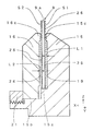
- 2A is a schematic plan view showing a spindle used in the cutting apparatus shown in FIG.
- FIG. 2B is a schematic right side view showing a spindle used in the cutting apparatus shown in FIG.
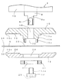
- FIG. 3 is a schematic exploded sectional view showing components of the spindle shown in FIGS. 2A and 2B.
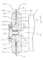
- FIG. 4 is a schematic cross-sectional view showing a state in which the constituent members shown in FIG. 3 are fixed to the spindle.
- FIG. 5 is a schematic sectional view showing the rotary blade and the flange shown in FIG. 4 and the rotary blade and the flange used in the cutting apparatus according to Embodiment 2 of the present invention in an enlarged manner.
- the spindle 7 is provided with a first flange 15 and a second flange 16 that are fixed to the rotary shaft 8 with the rotary blade 9 sandwiched from both sides.
- the first flange 15 has an annular holding portion 15c that is in close contact with the abrasive grains formed on the first surface S1 of the rotary blade at the outer peripheral portion, and a first concave portion 19 that is annularly formed inside the holding portion 15c. And provide.
- An annular holding portion 16c that is in close contact with the abrasive grains formed on the second surface S2 of the rotary blade 9 at the outer peripheral portion on the second flange 16, and a second concave portion 24 that is annularly formed inside the holding portion 16c.
- the first concave portion 19 and the second concave portion 24 are arranged to face each other with the rotary blade 9 interposed therebetween.
- the distance L1 from the first surface S1 of the rotary blade 9 to the inner bottom surface of the first recess 19 is equal to the distance L2 from the second surface S2 of the rotary blade 9 to the inner bottom surface of the second recess 24.
- the predetermined distance is larger than the maximum diameter of the abrasive grains 26 and smaller than the maximum value of the deformation amount in a range where the deformation of the rotary blade 9 is allowed.
- Embodiment 1 of a cutting device according to the present invention will be described with reference to FIG. Any figure in the present application document is schematically omitted or exaggerated as appropriate for easy understanding. About the same component, the same code
- the cutting device 1 is a device that divides a workpiece into pieces by cutting the object to be cut.
- the cutting apparatus 1 includes a substrate supply module A, a substrate cutting module B, and an inspection module C as components.
- Each component (each module A to C) is detachable and replaceable with respect to other components.
- the substrate supply module A is provided with a substrate supply mechanism 3 that supplies a sealed substrate 2 corresponding to an object to be cut, and a control unit CTL that performs operation and control of the cutting apparatus 1.
- the sealed substrate 2 is a substrate made of a printed circuit board or a lead frame, a plurality of functional elements (chips such as semiconductor elements) mounted in a plurality of regions of the substrate, and a plurality of regions are collectively covered.
- the sealing resin thus formed is included.
- the sealed substrate 2 is an object to be cut that is finally cut into pieces.
- the sealed substrate 2 is transported to the substrate cutting module B by a transport mechanism (not shown).
- the cutting device 1 shown in FIG. 1 is a single-cut table type cutting device. Accordingly, the substrate cutting module B is provided with one cutting table 4.
- the cutting table 4 can be moved in the Y direction in the figure by the moving mechanism 5 and can be rotated in the ⁇ direction by the rotating mechanism 6.
- a cutting jig (not shown) is fixed to the cutting table 4, and the sealed substrate 2 is placed on the cutting jig.
- the substrate cutting module B is provided with a spindle 7 as a cutting mechanism.
- the cutting device 1 shown in FIG. 1 is a cutting device having a single spindle configuration in which one spindle 7 is provided.
- the spindle 7 can move independently in the X direction and the Z direction.
- the spindle 7 includes a rotating shaft 8 and a disk-shaped rotating blade 9 attached to the tip of the rotating shaft 8.
- the rotary blade 9 is disposed in parallel to a plane (a plane including the Y axis and the Z axis) orthogonal to the axial direction (X direction) of the rotary shaft 8.
- the spindle 7 is provided with a cutting water nozzle (not shown) for injecting cutting water in order to suppress frictional heat generated by the rotary blade 9 rotating at high speed.
- the sealed substrate 2 is cut by relatively moving the cutting table 4 and the spindle 7.
- the rotary blade 9 cuts the sealed substrate 2 by rotating in a plane including the Y axis and the Z axis.
- the inspection module C is provided with an inspection table 10. On the inspection table 10, an aggregate made up of a plurality of products P cut into pieces by cutting the sealed substrate 2, that is, a cut substrate 11 is placed. The plurality of products P are inspected by a camera for inspection (not shown) and sorted into non-defective products and defective products. The non-defective product is stored in the tray 12.
- the single-cut table type single-spindle cutting apparatus 1 has been described.
- the present invention is not limited to this, and a single-cut table type cutting device having a twin spindle configuration or a twin-cut table type cutting device having a twin spindle configuration may be used.
- the spindle 7 used in the cutting device 1 according to the present invention will be described with reference to FIGS. 2A to 5.
- the spindle 7 that is a cutting mechanism includes a spindle main body 13, a spindle motor 14 that is a drive mechanism, and a rotating shaft 8 that is connected to the spindle motor 14.
- the rotary shaft 8 is rotatably supported on the spindle 7 in a non-contact state by air (air) blown from a radial air bearing and an axial air bearing (not shown).
- a rotary blade 9 for cutting the sealed substrate 2 is attached to the tip of the rotary shaft 8.
- the rotary blade 9 is disposed in parallel to a plane (a plane including the Y axis and the Z axis) orthogonal to the axial direction (X direction) of the rotary shaft 8.
- the rotary blade 9 is sandwiched between the first flange 15 and the second flange 16 which are fixed members.
- the first flange 15 and the second flange 16 are fixed to the rotary shaft 8 with the rotary blade 9 interposed therebetween.
- the rotary blade 9 is a washer type rotary blade having a through hole.
- the rotary blade 9 can be attached to and detached from the spindle 7 and can be exchanged.
- the rotary shaft 8 provided on the spindle 7 has a tip 8a having a small diameter in order to fix the first flange 15 to the tip.
- a female screw portion 8 i to which a bolt 17 for fixing the first flange 15 to the rotary shaft 8 is screwed is formed at the distal end portion 8 a of the rotary shaft 8.
- the first flange 15 and the second flange 16 are members that hold the rotary blade 9 by clamping. With the first flange 15 and the second flange 16 sandwiching the rotary blade 9, the first flange 15 and the second flange 16 are fixed and integrated. Of the integrated first flange 15 and second flange 16, the first flange 15 is fixed to the rotary shaft 8 by a bolt 17.
- the first flange 15 is a rear flange disposed on the first surface S1 (the surface on the spindle 7 side) of the rotary blade 9.
- the first flange 15 is directly fixed to the rotating shaft 8.
- a through hole 18 is provided at the center of the first flange 15 so as to be fitted to the tip 8 a of the rotating shaft 8.
- the first flange 15 is provided with a cylindrical base portion 15a into which the rotary blade 9 is inserted, and a cylindrical base portion 15b into which the second flange 16 is fitted.
- a holding portion 15 c made of a convex portion formed in an annular shape (preferably an annular shape) for holding the rotary blade 9 is provided on the outer peripheral portion of the first flange 15.
- the first flange 15 is provided with a first recess 19 formed in an annular shape (preferably an annular shape) in order to suppress deformation of the rotary blade 9.
- the outer peripheral portion of the rotary blade 9 refers to a portion that does not include the outer edge of the rotary blade 9 but includes a portion slightly inside from the outer edge, in addition to the portion including the outer edge of the rotary blade 9. Including.
- the annular holding portion 15 c is provided at a position corresponding to the outer peripheral portion of the rotary blade 9.
- the 1st recessed part 19 is provided in the part which entered inside from the holding
- the rotary blade 9 is a washer-type rotary blade having a through hole 22 and formed in an annular shape.
- the through hole 22 of the rotary blade 9 is inserted into the cylindrical base portion 15a of the first flange.
- the rotary blade 9 is made of, for example, an annular grindstone in which abrasive grains such as diamond are bonded with a binding material such as metal, resin, or ceramic.
- abrasive grains used for cutting a sealed substrate diamond abrasive grains having a particle size of about several ⁇ m to several tens of ⁇ m are often used.
- the second flange 16 is a front flange disposed on the second surface S2 of the rotary blade 9 (the surface on the side opposite to the spindle 7 and the surface opposite to the first surface S1).
- the second flange 16 is fitted to the first flange 15.
- a through hole 23 is provided at the center of the second flange 16 so as to be fitted to the cylindrical base portion 15 b of the first flange 15.
- a holding portion 16 c made of a convex portion formed in an annular shape (preferably an annular shape) for holding the rotary blade 9 is provided on the outer peripheral portion of the second flange 16.
- the second flange 16 is provided with a second recess 24 formed in an annular shape (preferably an annular shape) in order to suppress deformation of the rotary blade 9.
- the holding portion 16 c is provided at a position corresponding to the outer peripheral portion of the rotary blade 9.
- the holding part 15c and the holding part 16c are provided at positions facing each other with the rotary blade 9 interposed therebetween.
- the 2nd recessed part 24 is provided in the part which entered inside from the holding
- the first concave portion 19 and the second concave portion 24 are provided at positions facing each other with the rotary blade 9 interposed therebetween. Similar to the depth of the first recess 19, the depth of the second recess 24 is formed to such a depth that the abrasive grains of the rotary blade 9 do not contact the inner bottom surface of the second recess 24.
- the rotary blade 9 is held by being sandwiched between an annular holding portion 15 c provided on the outer peripheral portion of the first flange 15 and an annular holding portion 16 c provided on the outer peripheral portion of the second flange 16.
- the rotary blade 9 is held so as to be parallel to a plane orthogonal to the axial direction of the rotary shaft 8.
- the end surface of the holding portion 15c (the lower surface of the holding portion 15c in FIG. 3) is a surface that comes into contact (contact) with the first surface S1 of the rotary blade 9.
- the end surface of the holding portion 15c comes into contact (adhesion) with the abrasive grains formed on the first surface S1 of the rotary blade 9.
- the end surface of the holding portion 16c (the upper surface of the holding portion 16c in FIG. 3) is a surface that comes into contact (contact with) the second surface S2 of the rotary blade 9.
- the end surface of the holding portion 16c comes into contact (adhesion) with the abrasive grains formed on the second surface S2 of the rotary blade 9.
- the end surface of the holding portion 15c and the end surface of the holding portion 16c have high flatness.
- the nut 21 is a flange nut for fixing the second flange 16 to the first flange 15.
- a nut female screw portion 21 i is formed on the inner peripheral surface of the nut 21.
- the bolt 17 is a fixing member for fixing the first flange 15 and the second flange 16 fixed to the rotary shaft 8 by the nut 21 with the rotary blade 9 interposed therebetween.
- the bolt 17 is formed with a male screw portion 17 e that is screwed to the female screw portion 8 i of the rotating shaft 8.
- a hexagonal hole 25 is formed at the head of the bolt 17 in order to rotate the bolt 17 when the bolt 17 is screwed to the rotating shaft 8 or when the bolt 17 is loosened from the rotating shaft 8.
- the procedure for mounting the rotary blade 9 on the spindle 7 will be described.
- the through hole 22 of the rotary blade 9 is inserted into the cylindrical base portion 15 a of the first flange 15.
- the through hole 23 of the second flange 16 is fitted into the cylindrical base portion 15 b of the first flange 15.
- the nut female screw portion 21 i of the nut 21 is screwed into the nut male screw portion 15 e formed at the tip portion of the first flange 15 and tightened.
- the rotary blade 9 is sandwiched and fixed between the first flange 15 and the second flange 16.
- the through hole 18 formed at the center of the first flange 15 is formed at the tip 8 a of the rotary shaft 8 of the spindle 7.
- the bolt 17 is screwed into the female screw portion 8 i formed at the tip portion 8 a of the rotating shaft 8 and tightened.
- an L-shaped hexagon wrench or the like is inserted into the hexagon hole 25 formed at the head of the bolt 17, and the bolt 17 is tightened.
- FIGS. 4 and 5 the state where the rotary blade 9 is mounted on the spindle 7 will be described.
- the rotary blade 9 is sandwiched between the first flange 15 and the second flange 16 and fixed by the nut 21.
- the fixed rotary blade 9 is fixed to the rotary shaft 8 by a bolt 17.
- the rotary blade 9 is sandwiched and fixed by a holding portion 15 c formed on the outer peripheral portion of the first flange 15 and a holding portion 16 c formed on the outer peripheral portion of the second flange 16.
- the end surface of the holding portion 15 c contacts (adheres) the abrasive grains 26 formed on the first surface S ⁇ b> 1 of the rotary blade 9.
- the end surface of the holding part 16c contacts (adheres) the abrasive grains 26 formed on the second surface S2 of the rotary blade 9.
- the sealed blade 2 (see FIG. 1) is cut by rotating the rotating blade 9 sandwiched and fixed between the end face of the holding portion 15c and the end face of the holding portion 16c at a high speed.
- the procedure for mounting the rotary blade 9 on the spindle 7 is the same as that in the present embodiment and the conventional technique (see paragraphs [0019] and [0020] in FIG. 3 and FIG. 3).
- the depth of the first recess 19 and the depth of the second recess 24 are different from the invention according to the present application.
- problems that occur when two flanges corresponding to the first flange 15 and the second flange 16 shown in FIG. 4 of the present application are used will be described with reference to FIG. 4 of the present application as appropriate. To do.
- the depth corresponding to the depth of the first recess 19 and the depth of the second recess 24 shown in FIG. 4 of the present application is about 0.3 mm to 0.5 mm.
- two recesses are formed.
- the rotary blade 9 is fixed by being sandwiched between the holding portion 15c and the holding portion 16c at the outer peripheral portions of the two flanges. As a result, the rotary blade 9 cannot be displaced outwardly along the radial direction by centrifugal force. Therefore, the rotary blade 9 receives a force toward the inner bottom surface of the first recess 19 formed in the first flange 15 or the inner bottom surface of the second recess 20 formed in the second flange 16. Therefore, the rotary blade 9 is deformed due to centrifugal force. Since both the first recess 19 and the second recess 24 have a depth of about 0.3 mm to 0.5 mm, the rotary blade 9 is deformed in the internal space corresponding to these depths.
- the amount of deformation of the rotary blade 9 may exceed the allowable range due to the centrifugal force. In this case, the rotary blade 9 is damaged in the internal space formed by the first flange 15 and the first surface S1 and the internal space formed by the second flange 16 and the second surface S2. There is a fear.
- the first flange 15 and the second flange 16 are formed with the first recess 19 and the second recess 24, respectively.
- the first recess 19 and the second recess 24 have a very small depth.
- the rotary blade 9 is configured by bonding a large number of abrasive grains 26 made of, for example, diamond to the surface of a bonding material 9 a called a bond.
- the abrasive grains 26 included in the rotary blade 9 are embedded in the vicinity of the surface of the binder 9a.
- the abrasive grains 26 contained in the rotary blade 9 have a particle size of several ⁇ m to several tens of ⁇ m.
- the distance from the first surface S1 of the rotary blade 9 to the inner bottom surface of the first recess 19 is L1.
- the distance from the 2nd surface S2 which the rotary blade 9 has to the inner bottom face of the 2nd recessed part 24 is set to L2.
- the distance L1 from the first surface S1 of the rotary blade 9 to the inner bottom surface of the first recess 19 and the distance L2 from the second surface S2 of the rotary blade 9 to the inner bottom surface of the second recess 24 are rotations. It is set to be slightly larger than the maximum value of the particle size of the abrasive grains 26 contained in the blade 9. In addition, the distance L1 and the distance L2 are set to be equal predetermined distances.
- the maximum particle size of the abrasive grains 26 formed on the rotary blade 9 is 15 ⁇ m.
- the distance L1 from the first surface S1 to the inner bottom surface of the first recess 19 is slightly larger than the maximum value of the particle size of the abrasive grains 26 formed on the rotary blade 9.
- it is set to 0.02 mm ( 20 ⁇ m).
- the distance L2 from the second surface S2 to the inner bottom surface of the second recess 24 is set to be slightly larger than the maximum value of the grain size of the abrasive grains 26 formed on the rotary blade 9 and the distance.
- An abrasive grain 26 is assumed.
- the maximum amount of the abrasive grains 26 protruding from the surface of the binding material 9a is 15 ⁇ m when the abrasive grains 26 are slightly embedded in the binding material 9a. The value is slightly less than
- the abrasive grains 26 prevent the deformation that has been increased to slightly exceed 5 ⁇ m from being further deformed. Therefore, even if deformation occurs in the rotary blade 9 due to the centrifugal force acting on the rotary blade 9, the deformation is suppressed to a minute deformation amount (for example, a deformation amount slightly exceeding 5 ⁇ m). .
- the distance L1 from the first surface S1 to the inner bottom surface of the first recess 19 and the distance L2 from the second surface S2 to the inner bottom surface of the second recess 24 allow deformation of the rotary blade 9. It is set to be smaller than the maximum value of the deformation amount in the range. Therefore, the deformation of the rotary blade 9 is suppressed to the maximum value or less.
- the concave portion 19 of the first flange 15 and the concave portion 24 of the second flange 16 are provided so as to face each other with the rotary blade 9 interposed therebetween.
- the distance L1 from the first surface S1 of the rotary blade 9 to the inner bottom surface of the first recess 19 and the distance L2 from the second surface S2 of the rotary blade 9 to the inner bottom surface of the second recess 24 are It is preset at an equal predetermined distance.
- the set predetermined distance is larger than the maximum diameter of the abrasive grains 26 of the rotary blade 9 and smaller than the maximum value of the deformation amount in the range where the deformation of the rotary blade 9 is allowed.
- the abrasive grains 26 protruding from the first surface S1 come into contact with the inner bottom surface of the first recess 19 at an early stage.
- the abrasive grains 26 protruding from the second surface S2 come into contact with the inner bottom surface of the second recess 24 at an early stage.
- the inner bottom surface of the first concave portion 19 and the inner bottom surface of the second concave portion 24 prevent the deformation of the rotary blade 9 from being increased at a minute stage. Therefore, even when the rotary blade 9 rotates at a high speed, damage to the rotary blade 9 caused by centrifugal force is prevented.
- the term “equal distance” means that the distances are strictly different, but the difference between the distances is small enough to suppress the deformation of the rotary blade 9 from becoming large. including.
- the phrase “equal distance” includes the case where the distances are substantially equal.
- Both the holding portion 15c formed on the first flange 15 and the holding portion 16c formed on the second flange 16 have an annular (preferably annular) shape.
- at least one of the holding portions 15c and 16c may have a shape in which an annular (preferably annular) convex portion over the entire circumference is partially interrupted.
- At least one of the holding portions 15c and 16c may be a convex portion having a width in a polygonal shape.
- at least one of the first concave portion 19 and the second concave portion 24 has a shape in which an annular (preferably annular) concave portion over the entire circumference is partially interrupted. Also good.
- At least one of the first concave portion 19 and the second concave portion 24 may be a concave portion having a width of a polygonal shape.
- At least one of the first recess 19 and the second recess 24 has a plurality of line-shaped recesses having a width in the radial direction along the outer periphery of the rotary blade 9, or a plurality of having a width in the radial direction. You may have a curved recessed part.
- annular means a shape including the shapes of the holding portions 15c and 16c, the first concave portion 19 and the second concave portion 24 described so far.
- the cutting device includes the spindle 7 described above.
- the reason why the deformation at the cutting edge of the rotary blade 9 cannot be sufficiently suppressed is that the first flange 15 and the second flange 16 are deformed due to centrifugal force.
- at least one of the outer peripheral portion of the first flange 15 and the outer peripheral portion of the second flange 16 extends from the surface of the rotary blade 9 along the axial direction of the rotary shaft 8 (see FIG. 4). It may be deformed to bend in the direction of leaving.
- the end face of the holding portion (at least one of the holding portions 15c or 16c) of the deformed flange is closer to the rotary shaft 8 when the rotary blade 9 is stopped. You may incline so that it may leave
- the inclined end surface is indicated by a thin broken line.
- the angle (inclination) of the end surface of the holding portion 15c with respect to the first surface S1 of the rotary blade 9 is adjusted.
- the angle (inclination) of the end surface of the holding portion 16c with respect to the second surface S2 of the rotary blade 9 is adjusted. According to the present embodiment, the deformation of the cutting edge of the rotary blade 9 is suppressed by executing at least one of these adjustments.
- the sealed substrate 2 in which the sealing resin is formed on the substrate is cut as the object to be cut is shown.
- a sealed substrate in which a glass epoxy laminated board, a printed wiring board, a ceramic substrate, a metal base substrate, a film base substrate, etc. are used as a substrate in an object to be cut and a sealing resin is formed thereon.
- the present invention is also applied.
- Functional elements include sensors, filters, actuators, oscillators, etc. in addition to semiconductor elements such as ICs (Integrated Circuits), transistors, and diodes.
- ICs Integrated Circuits
- transistors transistors
- diodes diodes
- the present invention is also applied to the case of cutting an object having a substantially circular shape such as a wafer level package in which a silicon semiconductor or a compound semiconductor wafer remains in a wafer state and is encapsulated with a resin.
- the present invention is also applied to the case of cutting a silicon semiconductor or compound semiconductor wafer itself.
- the object to be cut is not limited to the sealed substrate 2 (see FIG. 1).
- a plate-shaped member (resin molded body) manufactured by the resin molding method is cut to manufacture a product such as an optical component such as a lens array or a general resin molded product.
- the resin molded body in this case is included in the object to be cut.
- the present invention is not limited to the above-described embodiments, and can be arbitrarily combined, modified, or selected and adopted as necessary within the scope not departing from the gist of the present invention. It is.
Landscapes
- Engineering & Computer Science (AREA)
- Mechanical Engineering (AREA)
- Mining & Mineral Resources (AREA)
- Life Sciences & Earth Sciences (AREA)
- Forests & Forestry (AREA)
- Polishing Bodies And Polishing Tools (AREA)
- Dicing (AREA)
- Finish Polishing, Edge Sharpening, And Grinding By Specific Grinding Devices (AREA)
- Nonmetal Cutting Devices (AREA)
- Processing Of Stones Or Stones Resemblance Materials (AREA)
Abstract
L'invention concerne un dispositif de coupe comportant un premier rebord et un deuxième rebord fixé sur un arbre rotatif dans un état permettant de prendre en sandwich une lame rotative. Le premier rebord comporte une partie de retenue annulaire en contact étroit au niveau de la partie périphérique extérieure de celui-ci avec une première surface de la lame rotative, et un premier évidement annulaire. Le deuxième rebord comporte une partie de retenue annulaire en contact étroit au niveau de la partie périphérique extérieure de celui-ci avec une deuxième surface de la lame rotative, et un deuxième évidement annulaire. Le premier évidement et le deuxième évidement sont disposés l'un en face de l'autre avec la lame rotative entre eux. La distance depuis la première surface jusqu'à la surface inférieure intérieure du premier évidement et la distance depuis la deuxième surface jusqu'à la surface inférieure intérieure du deuxième évidement sont réglées pour être supérieures à la grosseur maximale des grains abrasifs de la lame rotative, inférieures à la quantité maximale de déformation dans les limites de la plage de déformation admissible de la lame rotative, et égales l'une par rapport à l'autre. Quand la lame rotative se déforme, les grains abrasifs viennent en contact avec le premier évidement et le deuxième évidement.
Priority Applications (2)
| Application Number | Priority Date | Filing Date | Title |
|---|---|---|---|
| KR1020177030822A KR20180029951A (ko) | 2015-07-17 | 2016-06-28 | 절단 장치 및 절단 방법 |
| CN201680025726.8A CN107530859B (zh) | 2015-07-17 | 2016-06-28 | 切断装置及切断方法 |
Applications Claiming Priority (2)
| Application Number | Priority Date | Filing Date | Title |
|---|---|---|---|
| JP2015142588A JP2017024093A (ja) | 2015-07-17 | 2015-07-17 | 切断装置及び切断方法 |
| JP2015-142588 | 2015-07-17 |
Publications (1)
| Publication Number | Publication Date |
|---|---|
| WO2017013837A1 true WO2017013837A1 (fr) | 2017-01-26 |
Family
ID=57834170
Family Applications (1)
| Application Number | Title | Priority Date | Filing Date |
|---|---|---|---|
| PCT/JP2016/003101 Ceased WO2017013837A1 (fr) | 2015-07-17 | 2016-06-28 | Dispositif de coupe et procédé de coupe |
Country Status (5)
| Country | Link |
|---|---|
| JP (1) | JP2017024093A (fr) |
| KR (1) | KR20180029951A (fr) |
| CN (1) | CN107530859B (fr) |
| TW (1) | TWI599450B (fr) |
| WO (1) | WO2017013837A1 (fr) |
Cited By (1)
| Publication number | Priority date | Publication date | Assignee | Title |
|---|---|---|---|---|
| TWI672739B (zh) * | 2017-04-26 | 2019-09-21 | Towa Corporation | 產品製造裝置和製造方法 |
Families Citing this family (7)
| Publication number | Priority date | Publication date | Assignee | Title |
|---|---|---|---|---|
| JP6846669B2 (ja) * | 2017-03-09 | 2021-03-24 | 株式会社東京精密 | ブレード固定装置及びダイシング装置 |
| JP2018164964A (ja) * | 2017-03-28 | 2018-10-25 | Towa株式会社 | レジノイド砥石、レジノイド砥石の製造方法、及び、加工装置 |
| JP7127972B2 (ja) * | 2017-09-05 | 2022-08-30 | 株式会社ディスコ | 加工方法 |
| JP6612372B2 (ja) * | 2018-01-30 | 2019-11-27 | Towa株式会社 | フランジ交換機構、切断装置、フランジ交換方法および切断品の製造方法 |
| KR101990013B1 (ko) * | 2019-01-16 | 2019-06-17 | 김멋진 | 절단용 블레이드 및 이를 이용한 절단장치 |
| JP7169948B2 (ja) * | 2019-09-03 | 2022-11-11 | Towa株式会社 | フランジ端面修正装置、切断装置、フランジ端面修正方法及び切断品の製造方法 |
| KR102709971B1 (ko) * | 2022-03-18 | 2024-09-24 | 강주원 | 그라인딩 내부 절삭유 공급구조 |
Citations (5)
| Publication number | Priority date | Publication date | Assignee | Title |
|---|---|---|---|---|
| JP2000202770A (ja) * | 1999-01-14 | 2000-07-25 | Toshiba Mach Co Ltd | 薄刃砥石用砥石フランジ |
| JP2004358605A (ja) * | 2003-06-04 | 2004-12-24 | Nitolex Honsha:Kk | 研削ホイール |
| JP2005324438A (ja) * | 2004-05-14 | 2005-11-24 | Kuraimu:Kk | ブレード用フランジ |
| JP2011255458A (ja) * | 2010-06-09 | 2011-12-22 | Disco Corp | 切削加工装置 |
| JP2015085466A (ja) * | 2013-10-31 | 2015-05-07 | 株式会社ディスコ | フランジ機構 |
Family Cites Families (3)
| Publication number | Priority date | Publication date | Assignee | Title |
|---|---|---|---|---|
| JP2004348605A (ja) * | 2003-05-23 | 2004-12-09 | Tokyo Electron Ltd | 制御装置及び制御方法、処理装置、及びプログラム |
| DE102006032432B3 (de) * | 2006-07-13 | 2007-09-27 | Siltronic Ag | Sägeleiste sowie Verfahren zum gleichzeitigen Abtrennen einer Vielzahl von Scheiben von einem zylindrischen Werkstück unter Verwendung der Sägeleiste |
| JP5226394B2 (ja) * | 2008-06-16 | 2013-07-03 | 株式会社ディスコ | フランジの端面修正方法 |
-
2015
- 2015-07-17 JP JP2015142588A patent/JP2017024093A/ja active Pending
-
2016
- 2016-06-28 KR KR1020177030822A patent/KR20180029951A/ko not_active Ceased
- 2016-06-28 WO PCT/JP2016/003101 patent/WO2017013837A1/fr not_active Ceased
- 2016-06-28 CN CN201680025726.8A patent/CN107530859B/zh active Active
- 2016-07-12 TW TW105121854A patent/TWI599450B/zh active
Patent Citations (5)
| Publication number | Priority date | Publication date | Assignee | Title |
|---|---|---|---|---|
| JP2000202770A (ja) * | 1999-01-14 | 2000-07-25 | Toshiba Mach Co Ltd | 薄刃砥石用砥石フランジ |
| JP2004358605A (ja) * | 2003-06-04 | 2004-12-24 | Nitolex Honsha:Kk | 研削ホイール |
| JP2005324438A (ja) * | 2004-05-14 | 2005-11-24 | Kuraimu:Kk | ブレード用フランジ |
| JP2011255458A (ja) * | 2010-06-09 | 2011-12-22 | Disco Corp | 切削加工装置 |
| JP2015085466A (ja) * | 2013-10-31 | 2015-05-07 | 株式会社ディスコ | フランジ機構 |
Cited By (1)
| Publication number | Priority date | Publication date | Assignee | Title |
|---|---|---|---|---|
| TWI672739B (zh) * | 2017-04-26 | 2019-09-21 | Towa Corporation | 產品製造裝置和製造方法 |
Also Published As
| Publication number | Publication date |
|---|---|
| JP2017024093A (ja) | 2017-02-02 |
| CN107530859B (zh) | 2019-07-12 |
| TW201703925A (zh) | 2017-02-01 |
| CN107530859A (zh) | 2018-01-02 |
| TWI599450B (zh) | 2017-09-21 |
| KR20180029951A (ko) | 2018-03-21 |
Similar Documents
| Publication | Publication Date | Title |
|---|---|---|
| WO2017013837A1 (fr) | Dispositif de coupe et procédé de coupe | |
| JP6430329B2 (ja) | 切断装置及び切断方法 | |
| US8029335B2 (en) | Wafer processing method | |
| JP5226394B2 (ja) | フランジの端面修正方法 | |
| KR101905199B1 (ko) | 범프가 부착된 디바이스 웨이퍼의 가공 방법 | |
| US20090036034A1 (en) | Semiconductor wafer and processing method for same | |
| TWI855240B (zh) | 研削方法 | |
| JP6803169B2 (ja) | 研削方法 | |
| TWI767022B (zh) | 基板處理方法及基板處理系統 | |
| JP7043346B2 (ja) | 切削装置 | |
| JP7682654B2 (ja) | 半導体装置の製造方法及び製造装置 | |
| JP5881938B2 (ja) | ワークの研削方法 | |
| KR20130007424A (ko) | 피가공물의 연삭 방법 | |
| TW201706077A (zh) | 切削刃及切削刃的安裝構造 | |
| JP6563766B2 (ja) | ウェーハの加工方法 | |
| TWI868253B (zh) | 切削刀具 | |
| JP6847512B2 (ja) | 切削装置及び切削方法 | |
| TWI747296B (zh) | 法蘭盤端面修正裝置、切斷裝置、法蘭盤端面修正方法以及切斷品的製造方法 | |
| JP2007227594A (ja) | 切断治具、及び光学基板ウェハの切断方法 | |
| JP2009126006A (ja) | ワークの切削加工方法 | |
| JP6440560B2 (ja) | 修正器具 | |
| JP7446667B2 (ja) | 切削ブレード、切削ブレードの装着方法、及び被加工物の加工方法 | |
| JP7477325B2 (ja) | 加工方法 | |
| JP7055557B2 (ja) | パッケージ基板用フレーム及びパッケージ基板の研削方法 | |
| WO2024142799A1 (fr) | Procédé d'usinage de pièce |
Legal Events
| Date | Code | Title | Description |
|---|---|---|---|
| 121 | Ep: the epo has been informed by wipo that ep was designated in this application |
Ref document number: 16827405 Country of ref document: EP Kind code of ref document: A1 |
|
| ENP | Entry into the national phase |
Ref document number: 20177030822 Country of ref document: KR Kind code of ref document: A |
|
| NENP | Non-entry into the national phase |
Ref country code: DE |
|
| 122 | Ep: pct application non-entry in european phase |
Ref document number: 16827405 Country of ref document: EP Kind code of ref document: A1 |