WO2017013873A1 - Dispositif, système et procédé de mesure de dimension - Google Patents
Dispositif, système et procédé de mesure de dimension Download PDFInfo
- Publication number
- WO2017013873A1 WO2017013873A1 PCT/JP2016/003389 JP2016003389W WO2017013873A1 WO 2017013873 A1 WO2017013873 A1 WO 2017013873A1 JP 2016003389 W JP2016003389 W JP 2016003389W WO 2017013873 A1 WO2017013873 A1 WO 2017013873A1
- Authority
- WO
- WIPO (PCT)
- Prior art keywords
- reference scale
- lens
- dimension
- pattern
- image
- Prior art date
- Legal status (The legal status is an assumption and is not a legal conclusion. Google has not performed a legal analysis and makes no representation as to the accuracy of the status listed.)
- Ceased
Links
Images





Classifications
-
- G—PHYSICS
- G06—COMPUTING OR CALCULATING; COUNTING
- G06T—IMAGE DATA PROCESSING OR GENERATION, IN GENERAL
- G06T7/00—Image analysis
- G06T7/70—Determining position or orientation of objects or cameras
- G06T7/73—Determining position or orientation of objects or cameras using feature-based methods
- G06T7/74—Determining position or orientation of objects or cameras using feature-based methods involving reference images or patches
-
- G—PHYSICS
- G01—MEASURING; TESTING
- G01B—MEASURING LENGTH, THICKNESS OR SIMILAR LINEAR DIMENSIONS; MEASURING ANGLES; MEASURING AREAS; MEASURING IRREGULARITIES OF SURFACES OR CONTOURS
- G01B11/00—Measuring arrangements characterised by the use of optical techniques
- G01B11/02—Measuring arrangements characterised by the use of optical techniques for measuring length, width or thickness
-
- G—PHYSICS
- G06—COMPUTING OR CALCULATING; COUNTING
- G06T—IMAGE DATA PROCESSING OR GENERATION, IN GENERAL
- G06T1/00—General purpose image data processing
- G06T1/0007—Image acquisition
-
- H—ELECTRICITY
- H04—ELECTRIC COMMUNICATION TECHNIQUE
- H04N—PICTORIAL COMMUNICATION, e.g. TELEVISION
- H04N13/00—Stereoscopic video systems; Multi-view video systems; Details thereof
- H04N2013/0074—Stereoscopic image analysis
- H04N2013/0081—Depth or disparity estimation from stereoscopic image signals
Definitions
- the present invention relates to a dimension measuring apparatus, a dimension measuring system, and a dimension measuring method for measuring the dimension of an object.
- the following methods have been proposed as a method for measuring an object using an image taken by a camera. That is, the measurer places or projects a marker (reference scale) having a pattern indicating the length reference of the dimension on the measurement surface (the surface of the measurement object or an extended plane of the measurement object), and the reference scale and An image is picked up by an image pickup device such as a camera so that both the object to be measured and the object are within the image. Then, the measuring apparatus calculates the ratio (length, area, circumference length, etc.) of the measurement object by calculating the ratio between the reference scale and the measurement object from the above-described image data, and outputs it.
- a marker reference scale
- an image pickup device such as a camera
- Patent Document 1 describes a method for accurately measuring a dimension by converting an image of a rectangular marker having a known dimension on a measurement surface into a front image, which is an image captured from an oblique direction. .
- Patent Document 2 describes a method of measuring the dimensions of a rectangular parallelepiped using a marker whose dimensions are known on the measurement surface.
- Patent Document 3 discloses a technique for measuring the relative relationship (position, angle, etc.) between a marker and an observation object for observing the marker from the shade pattern of the marker, using a marker combining a lenticular lens and a monochrome pattern. Is described.
- Patent Document 1 can convert an image captured from an oblique direction into a front image, but the measurement accuracy of dimensions is reduced when a rectangular marker (reference scale) is not arranged or projected on the measurement surface (for example, deviated from the measurement surface). To do.
- Patent Document 2 describes a method of measuring the dimensions of a rectangular parallelepiped using a marker whose dimensions are known on the measurement surface. However, if the reference scale is not placed or projected on the measurement surface, it is difficult to maintain the accuracy of dimension measurement.
- Patent Document 3 uses a marker that combines a lenticular lens and a black and white pattern, and is a technique for measuring the relative relationship (position, angle, etc.) between the marker and an observation object that observes the marker. It is not a technique for accurately measuring the dimensions of objects.
- An object of the present invention is to provide a dimension measuring apparatus, a dimension measuring system, and a dimension measuring method capable of solving the above-described problems and maintaining measurement accuracy even when a reference scale is not arranged or projected on a measurement surface. .
- the dimension measuring apparatus provides a film having a pattern for displaying a length reference and a reference scale including a lens in contact with the film and a predetermined angle formed by the optical axis of the imaging apparatus on the lens. Based on a relationship between a pattern function indicating the length reference displayed on the imaging device and an imaging color function indicating the length reference imaged on the imaging device, the length reference from the captured image data including the reference scale.
- a reference scale extraction means for extracting an image formed by imaging
- a measurement object extraction means for extracting an image of the measurement object from photographed image data including the reference scale, and a size of the image formed by imaging the length reference
- a dimension calculation means for calculating the dimension of the measurement object based on the image of the measurement object.
- a film having a pattern for displaying a length reference and a reference scale including a lens in contact with the film and a change in a predetermined angle formed by the optical axis of the imaging device are performed on the lens.
- the length reference from the captured image data including the reference scale The image of the measurement object is extracted, the image area of the measurement object is extracted from the captured image data including the reference scale, and the dimension of the image formed of the length reference and the image of the measurement object are extracted. Based on this, the dimensions of the measurement object are calculated.
- the measurement accuracy can be maintained even when the reference scale is not arranged or projected on the measurement surface.
- FIG. 1 is a diagram illustrating an example of a configuration of a reference scale according to the first embodiment of the present invention.
- FIG. 2 is an enlarged cross-sectional view showing a part of the reference scale according to the first embodiment of the present invention.
- FIG. 3 is a diagram for explaining the principle of the reference scale according to the first embodiment of the present invention.
- FIG. 4 is a diagram showing an example of a dimension measuring system using a reference scale according to the first embodiment of the present invention.
- FIG. 5 is a functional block diagram showing an example of the functional configuration of the dimension measuring device and the storage device in the dimension measuring system according to the first embodiment of the present invention.
- FIG. 6 is a diagram showing an example of a processing flow in the dimension measuring apparatus according to the first embodiment of the present invention.
- FIG. 1 is a diagram illustrating an example of a configuration of a reference scale according to the first embodiment of the present invention.
- FIG. 2 is an enlarged cross-sectional view showing a part of the reference scale according to the first
- FIG. 7 is a diagram showing an example of the configuration of the reference scale according to the second embodiment of the present invention.
- FIG. 8 is a diagram illustrating an example of the configuration of the reference scale according to the third embodiment of the present invention.
- FIG. 9 is a diagram illustrating an example of a configuration of a reference scale according to the fourth embodiment of the present invention.
- FIG. 10 is a diagram illustrating an example of the configuration of the reference scale according to the fifth embodiment of the present invention.
- FIG. 11 is a diagram illustrating an example of the configuration of the dimension measuring apparatus according to the sixth embodiment of the present invention.
- the first embodiment is directed to the dimension measurement system 100 (FIG. 4), the following description will be given mainly with reference to the reference scale 3000 using FIGS. 4 to 6, the entire dimension measuring system 100 will be described.
- the reference scale 3000 and the dimension measuring system 100 according to the present invention are not limited to the configuration and processing shown in FIGS.
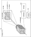
- FIG. 1 is a diagram illustrating an example of a configuration of a reference scale 3000 according to the first embodiment.
- the reference scale 3000 includes a film 2000 and a lenticular lens 1000 attached in contact with the upper surface of the film 2000.
- the film 2000 is a thin film member in which a black pattern pattern is printed on a white film member using printing or the like, or a white pattern pattern is printed on a black film member using printing or the like. It is a thin film member applied to the surface.
- the film 2000 may be formed by combining white and black films, or a pattern may be formed by polarized light by combining polarizing plates having different polarization directions. Further, the pattern of the film 2000 may be displayed on a liquid crystal monitor.
- the structure of the film 2000 and the pattern formation method are not limited to those shown in FIG.
- the film 2000 is preferably disposed at the focal length from the optical center of the lenticular lens 1000.
- the place where the film 2000 is disposed may be before and after the focal length within a range in which the measurement error can be allowed in actual use.
- the lenticular lens 1000 is used as an example of the lens of the reference scale 3000, but the lens used for the reference scale 3000 of the present embodiment is not limited to this.
- the reference scale 3000 according to the present embodiment is disposed to be inclined with respect to the measurement surface 200 (see FIG. 3), or even if the angle between the reference scale 3000 and the measurement surface 200 changes due to a change over time.
- the principle of reducing the variation of the pattern on the film 2000 indicating the length standard observed from the viewpoint of the imaging device 5000 (see FIG. 3) will be described.
- FIG. 2 is an enlarged cross-sectional view showing a part of the reference scale 3000 according to the first embodiment of the present invention.
- the lenticular lens 1000 has a structure in which a large number of plano-convex cylindrical lenses 1000A are arranged in one direction.
- FIG. 2 is a cross-sectional view of a plane-convex cylindrical lens (hereinafter, also simply referred to as a lens) 1000A of the lenticular lens 1000 on a plane orthogonal to the generatrix direction.
- the bus line refers to an axis that is parallel to the Y axis in FIG. 1 and has no imaging ability of the planoconvex cylindrical lens 1000A.
- the lens pitch be P L and the focal length be f.
- the film 2000 (specifically, the pattern of the film 2000) is preferably disposed at the position of the focal length f of the lens from the optical center of the lens, it is the focal length f in the following discussion.
- the reference scale 3000 has a configuration in which the lenticular lens 1000 is used and the film 2000 is disposed immediately below the lenticular lens 1000.
- the coordinate system is determined so that the X axis is taken in a direction perpendicular to the generatrix direction of the bottom surface of the lenticular lens 1000 and the intersection point of the optical axis 400 and the bottom surface of the lenticular lens 1000 is the origin O.
- FIG. 3 is a diagram for explaining the principle of the reference scale 3000 according to the first embodiment of the present invention.
- the reference scale 3000 is installed at an angle ⁇ with respect to the measurement surface 200, and is observed by the imaging device 5000 from a position that is a distance L from the measurement surface 200. It is assumed that the optical axis 300 of the imaging device 5000 is perpendicular to the measurement surface 200. In addition, although it demonstrates using a camera for the imaging device 5000 here, this is an example and a person may observe with eyes and is not limited.
- the distance A between the imaging lens 5100 and the sensor surface 5200 is adjusted so that the plane of the distance L is in focus. In other words, the imaging device 5000 uses the lens formula when the focal length of the imaging lens 5100 is expressed as F.
- the U axis is an axis in a direction along the sensor surface 5200.
- the origin of the coordinate system is the intersection of the optical axis 300 and the measurement surface 200.
- the total number of lenticular lenses 1000 of the reference scale 3000 according to the present embodiment is N L , and numbers from 0 to (N L ⁇ 1) are assigned in order from the lens 1000A at one end of the lenticular lens 1000. (0th lens 1000 (0) to N L ⁇ 1th lens 1000 (N L ⁇ 1)). Then, the X axis is taken on the bottom surface of the lenticular lens 1000, and a coordinate system with the center position of the reference scale 3000 as the origin is determined.
- the position (coordinates) x k on the X-axis of the k-th lens 1000 (K) is calculated using the lens pitch P L.
- the lenticular lens 1000 has a function of enlarging and projecting different positions on the X axis of the pattern of the film 2000 under the lenticular lens 1000 according to the angle of the viewing line of sight.
- equation (1) it can be seen that when the line-of-sight angle is ⁇ , the pattern at the position x k ⁇ f ⁇ tan ⁇ on the X-axis is magnified and displayed on the k-th lens 1000 (K). .
- the color of the pattern at this position is represented as C (x k ⁇ f ⁇ tan ⁇ ).
- C (x k ⁇ f ⁇ tan ⁇ ) is also referred to as a pattern function C.
- An angle ⁇ formed by the optical axis 300 of the imaging device 5000 and the optical axis 400 of the lenticular lens 1000 corresponds to the line-of-sight angle ⁇ discussed in FIG.
- optical center position x k of the k-th lens 1000 (K) is, after taking into consideration viewing angle theta, is imaged at a position u k on U-axis is given by the following equation.
- the value x k ⁇ cos ⁇ generated when the reference scale 3000 is inclined by the angle ⁇ is sufficiently smaller than the distance L between the imaging device 5000 and the measurement surface 200 (L >> x k ⁇ cos ⁇ ). Approximating that.
- the imaging color at this position on the sensor surface 5200 is represented as H (u k ).
- the image formed on the sensor surface 5200 is finally subjected to image processing such as demosaicing and noise removal after the spectral processing and analog / digital conversion processing by a camera, for example, by a dimension measurement system 100 described later. Converted to observations.
- the sensor surface 5200 is a human eye
- the sensor corresponds to the retina
- the image on the retina is converted into an electric signal by the visual cell and converted into an observation value perceived by the human through processing in the visual cortex.
- the observation value at the position u on the sensor surface 5200 after such conversion is represented as I (u).
- I (u) for example, an observation value function that is “1” when the imaging color at the position u on the sensor surface 5200 is white and “0” when the image color is black can be considered.
- observation value function that takes two values is an example, and the observation value is a scalar value such as a luminance value, or a vector value such as an RGB (Red Green Blue) color value or an HSV (Hue Saturation Value) color value.
- RGB Red Green Blue
- HSV Human Saturation Value
- other optical physical quantities such as light wavelength, phase, polarization characteristics, radiation intensity, and modulation amount, and psychophysical quantities such as sharpness and glossiness may be used, and are not limited.
- K-th lens 1000 pattern was projected on an enlarged scale in (K) of the reference scale 3000 is imaged at a position u k on U-axis shown in Equation (4). Even if the reference scale 3000 is disposed to be inclined with respect to the measurement surface 200, or the positional relationship between the reference scale 3000 and the measurement surface 200 changes due to a change with time, the length reference observed from the viewpoint of the imaging device 5000.
- the pattern color (pattern function C) and the imaging color function that are magnified and displayed on the lenticular lens 1000 of the reference scale 3000 The pattern of the film 2000 may be determined so that H (u k ) satisfies the following relational expression.
- the position at which the lenticular lens 1000 forms an image on the sensor surface 5200 is discrete (see equation (6)).
- the pattern indicating the length reference is a white belt-like pattern having a width of 10 cm on a black background. Further, it is assumed that a camera is used as the imaging device 5000.
- the image sensor of the imaging device 5000 has monochrome 256 gradations and a pixel size of 2.5 ⁇ m square lattice. Note that the parameters shown here are merely examples for explanation, and the present invention is not limited to these.
- the observation value function ⁇ (u) is a function that provides a predetermined threshold value for the pixel value of the photographed image data and is “1” if it is equal to or greater than the threshold value, and “0” otherwise. Accordingly, the default observation value function ⁇ (u) is defined as follows.
- u 0 is set as the center position.
- the image formation color function H (u) corresponding to this is as follows.
- the pattern function, forming the position x k -f ⁇ tan ⁇ on pattern enlarges lens 1000 (K) is, at the position u k of an image on the sensor surface 5200 of the lens 1000 (K) It is defined by the value of the image color function H (u k ).
- the reference scale 3000 is characterized by including the film having the pattern defined by the pattern function C and the lenticular lens 1000 disposed thereon.
- the pattern function of the pattern is a one-variable function defined in a direction orthogonal to the generatrix direction of the lenticular lens 1000, and the pattern at the position where the lens 1000 (K) expands and captures the pattern of the lens 1000 (K). It is a predetermined imaging pattern defined at the imaging position in the imaging apparatus 5000. Therefore, the pattern of the film 2000 is a one-dimensional pattern.
- standard observed can be considered to be a striped one-dimensional pattern, for example.
- the lenticular lens 1000 acts under the lenticular lens 1000.
- the different positions of the pattern of the arranged film 2000 are enlarged and projected. Thereby, the pattern indicating the length reference observed in the imaging apparatus 5000, that is, the fluctuation of the observation value I (u) is suppressed.
- the reference scale 3000 even if the angle between the reference scale 3000 and the measurement surface 200 changes with respect to the axis of the lenticular lens 1000 in the generatrix direction, the length reference observed in the imaging device 5000 is shown. Pattern fluctuation is suppressed. As a result, even if the reference scale 3000 is inclined with respect to the measurement surface 200, the angle between the reference scale 3000 and the measurement surface 200 changes with respect to the axis of the lenticular lens 1000 in the generatrix direction due to changes over time. However, there is an effect that the accuracy of dimension measurement can be continuously maintained.
- FIG. 4 is a diagram illustrating an example of the dimension measurement system 100 using the reference scale 3000 according to the first embodiment.
- the dimension measuring system 100 is a system for measuring the dimension of the measuring object 4000.
- the dimension measurement system 100 includes a reference scale 3000, a measurement object 4000, an imaging device 5000, a dimension measurement device 6000, a storage device 7000, and a display device 8000.
- the optical axis 300 of the imaging device 5000 is installed perpendicular to the measurement surface 200.
- the measurement surface 200 refers to a surface or a cross section on the measurement object 4000 for measurement, or an extended plane thereof.
- the reference scale 3000 is preferably installed so that the bottom surface of the reference scale 3000 is on the measurement surface 200. However, it may be moved back and forth in the direction of the optical axis 300 of the image pickup apparatus 5000 as long as the measurement error can be allowed in actual use.
- the devices are connected to each other using, for example, a LAN (Local Area Network) cable.
- LAN Local Area Network
- each device may be configured to be connected to each other wirelessly.
- the imaging device 5000 is a device that photographs the reference scale 3000 and the measurement object 4000.
- the imaging device 5000 is realized by, for example, a general digital camera or a web camera that can output image data having a number of pixels that can observe an image region including the measurement object 4000 and the reference scale 3000.
- the imaging device 5000 is realized by, for example, a web camera provided with a CCD (Charge Coupled Device) image sensor or a CMOS (Complementary Metal-Oxide-Semiconductor) image sensor having an output pixel number of 1920 ⁇ 1080 pixels. The invention is not limited to this.
- the reference scale 3000 and the measurement object 4000 are photographed simultaneously.
- the imaging device 5000 transmits image data (captured image data) indicating the captured reference scale 3000 and the image of the measurement object 4000 to the dimension measuring device 6000.
- the dimension measuring device 6000 receives captured image data from the imaging device 5000.
- the dimension measuring device 6000 measures the dimension of the measurement object 4000 using the received captured image data.
- a specific functional configuration of the dimension measuring apparatus 6000 will be described with reference to FIG.
- the storage device 7000 is a device in which the dimensions of the reference scale 3000 are stored in advance.
- the dimension of the reference scale 3000 refers to the actual dimension value (unit: cm, for example) of the pattern indicating the observed length standard. For example, in the case of a pattern defined by the pattern function exemplified above, information that “the white belt-like region is 10 cm in length” is stored.
- the display device 8000 is a means for displaying the processing result of the dimension measuring device 6000 and the image data taken by the imaging device 5000.
- FIG. 5 is a functional block diagram showing an example of functional configurations of the dimension measuring device 6000 and the storage device 7000 in the dimension measuring system 100 according to the present embodiment. Note that FIG. 5 also illustrates an imaging device 5000 and a display device 8000.
- the dimension measuring device 6000 includes a reference scale extracting unit 6100, a measurement object extracting unit 6200, and a dimension calculating unit 6300.
- the reference scale extraction unit 6100 receives captured image data from the imaging device 5000.
- the reference scale extraction unit 6100 is an image area (also referred to as an observation pattern) of the pattern of the film 2000 indicating the length reference displayed on the lenticular lens 1000 of the reference scale 3000 from the captured image represented by the received captured image data. ).
- the reference scale extraction unit 6100 uses color information to distinguish the photographed image into an observation pattern and other regions, and extracts the region distinguished by the observation pattern from the photographed image data.
- the observation pattern of the reference scale 3000 is, for example, a white band pattern on a black background and takes a binary example in the design of the pattern function described above.
- the reference scale extraction unit 6100 extracts the observation pattern by using such color and pattern features in the extraction process.
- the observation pattern may be extracted manually using image analysis software. Note that the observation pattern extraction processing performed by the reference scale extraction unit 6100 is not particularly limited, and a general method is used, and thus the description thereof is omitted in this embodiment.
- the measurement object extraction unit 6200 receives captured image data from the imaging device 5000.
- the measurement object extraction unit 6200 extracts an image area of the measurement object 4000 from the captured image represented by the received captured image data. Specifically, the measurement object extraction unit 6200 distinguishes the photographed image into the measurement object 4000 and other regions using color information, and the region distinguished by the measurement object 4000 is photographed image. Extract from the data. Alternatively, the image region of the measurement object 4000 may be extracted manually using image analysis software. Note that the extraction process of the measurement object 4000 performed by the measurement object extraction unit 6200 is not particularly limited, and a general method is used, and thus the description thereof is omitted in this embodiment.
- the dimension calculation unit 6300 includes an observation pattern generated by the reference scale extraction unit 6100 and an image region of the measurement target 4000 generated by the measurement target extraction unit 6200.
- the reference scale extraction unit 6100 and the measurement target extraction unit 6200 The unit of the image data of the observation pattern and the image area of the measurement object 4000 is usually a pixel, for example, when the imaging device 5000 is a camera.
- the dimension of the observation pattern is represented as S P (pixel), and the dimension of the measurement object 4000 is represented as W P (pixel).
- the actual size value of the measurement object 4000 is expressed as W R (cm). Although the unit of the actual size value is cm, this is an example and is not limited.
- the purpose of the size calculation unit 6300 is to calculate the actual value W R of the measurement object 4000.
- the dimension calculation unit 6300 refers to the dimension of the reference scale 3000 stored in the storage device 7000 (reference scale dimension storage unit 7100).
- the dimension of the reference scale 3000 is the actual dimension value S R (cm) of the pattern indicating the observed length reference.
- Actual value W R of the measurement object 4000 can be calculated by the following equation.
- the reference scale extraction unit 6100, the measurement object extraction unit 6200, and the dimension calculation unit 6300 are configured by hardware circuits such as logic circuits, for example.
- the storage device 7000 (reference scale dimension storage unit 7100) is constituted by a storage device such as a disk device or a semiconductor memory, for example.
- the display device 8000 is constituted by a display, for example.
- FIG. 6 is a diagram illustrating an example of a process flow in the dimension measuring apparatus 6000.
- the reference scale extraction unit 6100 uses the captured image data transmitted from the imaging device 5000 to obtain an observation pattern (an image area indicating a length reference displayed on the lenticular lens 1000 of the reference scale 3000. ) Is extracted (step S10).
- the measurement object extraction unit 6200 extracts the image area of the measurement object 4000 from the captured image data transmitted from the imaging device 5000 (step S20).
- the dimension calculation unit 6300 stores the actual dimension value SR of the reference scale observation pattern stored in the storage device 7000, the observation pattern extracted in step S10, and the image of the measurement object 4000 extracted in step S20.
- the actual size value of the measuring object 4000 is calculated from the area (step S30).
- the dimension measuring device 6000 can measure the dimension of the measuring object 4000 with the actual dimension value by this processing.
- the measurement accuracy can be maintained even when the reference scale 3000 is not arranged or projected on the measurement surface.
- the dimension measurement system 100 includes the following configuration.
- the dimension measurement system 100 includes a reference scale 3000 including a film 2000 having a pattern for displaying a length reference and a lenticular lens 1000 in contact with the film 2000.
- the reference scale extraction unit 6100 of the dimension measuring device 6000 is a pattern function that indicates the length reference displayed on the lens in accordance with a change in a predetermined angle formed by the reference scale and the optical axis 300 of the imaging device 5000. And a relationship between an image forming color function indicating a length reference for forming an image on the image pickup apparatus is used. That is, the reference scale extraction unit 6100 extracts an image formed by imaging the length reference from the captured image data including the reference scale 3000 based on the relationship.
- ⁇ Second Embodiment> Next, a second embodiment of the present invention will be described in detail with reference to the drawings.
- FIG. 7 is a diagram illustrating an example of the configuration of the reference scale 3100 according to the second embodiment.
- reference scale 3100 operates in the dimension measurement system 100 as in the first embodiment.
- the reference scale 3100 includes a film 2100 on which a pattern is formed and a lens 1100 attached in contact with the upper surface of the film 2100.
- the film 2100 is desirably disposed at the position of the focal length from the optical center of the lens 1100.
- the place where the film 2100 is arranged may be before and after the focal length within a range in which the measurement error can be allowed in actual use.
- a lens array is used as an example of the lens 1100, but the lens 1100 used for the reference scale 3100 of the present embodiment is not limited to this.
- the difference between the reference scale 3000 shown in FIG. 1 and the reference scale 3100 shown in FIG. 7 will be described.
- the pattern function of the film 2000 of the reference scale 3000 shown in FIG. 1 was a one-variable function defined in a direction orthogonal to the generatrix direction of the lenticular lens.
- the pattern function of the film 2100 of the reference scale 3100 shown in FIG. 7 is a two-variable function defined on a plane extending between the X axis and the Y axis.
- the pattern function is characterized in that the pattern at the position where the lens 1100 starts to expand is a predetermined imaging color function defined at the imaging position of the imaging device 5000 of the lens 1100. Therefore, the pattern of the film 2100 is a two-dimensional pattern. It is conceivable that the pattern indicating the observed length standard is, for example, a checkerboard-like two-dimensional pattern.
- the reference scale 3100 even if the reference scale 3000 is inclined with respect to the measurement surface 200, the reference scale 3100 and the measurement surface 200 are formed due to changes over time. Even if the angle changes, the variation of the pattern on the film 2100 indicating the length reference observed in the imaging device 5000 is suppressed.
- the reference scale 3000 in FIG. 1 is effective only for the angle change around one axis only in the direction of the generatrix of the lens. However, in the reference scale 3100 according to the present embodiment, either the X axis or the Y axis is used. The variation in the pattern indicating the length reference observed in the image pickup device 5000 can be suppressed even when the surrounding angle changes.
- the lens 1100 has a shape that brings about the same effect as the lenticular lens in both the X-axis cross section and the Y-axis cross section, and the same effect as in the first embodiment can be obtained.
- the measurement accuracy can be maintained even when the reference scale 3100 is not arranged or projected on the measurement surface with respect to an angle change around either the X axis or the Y axis. There is an effect.
- the pattern function of the film 2100 of the reference scale 3100 is a two-variable function defined on a plane extending between the X axis and the Y axis. This is because the lens 1100 has a shape that provides the same effect as the lenticular lens in both the X-axis cross section and the Y-axis cross section.
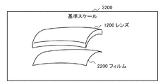
- FIG. 8 is a diagram illustrating an example of the configuration of the reference scale 3200 according to the third embodiment.
- reference scale 3200 operates in the dimension measurement system 100 as in the first embodiment.
- the reference scale 3200 includes a film 2200 on which a pattern is formed, and a lens 1200 attached in contact with the upper surface of the film 2200. It is desirable that the film 2200 is disposed at the focal distance from the optical center of the lens 1200. However, the place where the film 2200 is arranged may be before and after the focal length within a range in which the measurement error can be allowed in actual use.
- the difference between the reference scale 3000 shown in FIG. 1 and the reference scale 3200 shown in FIG. 8 is as follows. That is, the lens 1200 and the film 2200 of the reference scale 3200 shown in FIG. 8 are arbitrarily shaped curved surfaces (including a flat surface). On the other hand, the pattern function of the film 2200 is a two-variable function defined on a curved surface (including a plane).
- the lens 1200 and the film 2200 of the reference scale 3200 are curved surfaces (including a plane) having an arbitrary shape.
- the pattern function of the film 2200 is a two-variable function defined on a curved surface (including a plane).
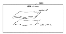
- FIG. 9 is a diagram illustrating an example of the configuration of the reference scale 3300 according to the fourth embodiment.
- reference scale 3300 operates in the dimension measurement system 100 as in the first embodiment.
- the reference scale 3300 includes a film 2300 on which a pattern is formed, and a lens 1300 that is attached in contact with the upper surface of the film 2300. It is desirable that the film 2300 is disposed at the focal length from the optical center of the lens. However, the place where the film 2300 is disposed may be before or after the focal length within a range in which the measurement error can be allowed in actual use.
- the difference between the reference scale 3200 shown in FIG. 8 and the reference scale 3300 shown in FIG. 9 is as follows. That is, the lens 1300 and the film 2300 of the reference scale 3300 shown in FIG. 9 are curved surfaces having arbitrary shapes and made of a deformable material. On the other hand, the pattern function of the film 2300 is a two-variable function defined on a curved surface (including a plane).
- the reference scale 3300 according to the present embodiment it is possible to obtain the same effect as the reference scale 3200 shown in FIG. The effect is higher. Even when the reference scale 3300 according to the present embodiment is installed on a flat surface or a curved surface whose shape is known, for example, the reference scale 3300 can be folded in a small size and can be easily transported.
- FIG. 10 is a diagram illustrating an example of the configuration of the reference scale 3400 according to the fifth embodiment.
- reference scale 3400 operates in the dimension measurement system 100 as in the first embodiment.
- the reference scale 3400 includes a film 2400 on which a pattern similar to that in FIG. 1 is formed, and a film 2410 on which only a pattern is formed (for displaying a length reference).
- the lens 2400 attached in contact with the upper surface of the film 2400 and the film 2410 is provided. It is desirable that the film 2400 and the film 2410 be disposed at the focal distance from the optical center of the lens 1400. However, the place where the film 2400 and the film 2410 are arranged may be before and after the focal length within a range where the measurement error can be allowed in actual use.
- a lenticular lens is used as an example of the lens 1400, but the lens 1400 used in the reference scale 3400 of the present embodiment is not limited to this.
- a film 2410 is added to the reference scale 3400.
- a QR (Quick Response) code registered trademark
- an AR (Augmented Reality) marker can be arranged on this film 2410.
- the QR code can be used as an identification ID by using, for example, image analysis software.
- the AR marker can be used to estimate the posture (position / angle) with respect to the imaging device 5000 on a plane on which the AR marker is arranged by using, for example, image analysis software.
- the same effect as that of the reference scale 3000 shown in FIG. 1 can be obtained, and additional information is embedded in the reference scale 3400 using the film 2410.
- a QR code is arranged on the film 2410
- an effect of identifying a plurality of different reference scales 3400 can be obtained by using, for example, image analysis software.
- an AR marker is arranged on the film 2410
- the posture (position / angle) of the reference scale 3400 with respect to the imaging device 5000 can be estimated by using, for example, image analysis software.
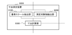
- FIG. 11 is a diagram illustrating an example of a configuration of a dimension measuring apparatus 9000 according to the sixth embodiment.
- the dimension measuring apparatus 9000 according to the present embodiment includes a reference scale extracting unit 9100, a measurement object extracting unit 9200, and a dimension calculating unit 9300.
- the reference scale extraction unit 9100 uses a reference scale composed of a film having a pattern for displaying a length reference and a lens in contact with the film. Then, the reference scale extraction unit 9100 includes a pattern function indicating a length reference displayed on the lens in accordance with a change in a predetermined angle formed by the reference scale and the optical axis of the imaging device, and a length reference that forms an image on the imaging device. The relationship with the imaging color function indicating That is, the reference scale extraction unit 9100 extracts an image formed by imaging the length reference from the captured image data including the reference scale based on the relationship.
- the measurement object extraction unit 9200 extracts an image of the measurement object from the captured image data including the reference scale.
- the dimension calculation unit 9300 calculates the dimension of the measurement object based on the dimension of the image formed by imaging the length reference and the image of the measurement object.
- the measurement accuracy can be maintained even when the reference scale is not arranged or projected on the measurement surface.
- the reference scale extraction unit 9100 is based on the relationship between the pattern function indicating the length reference displayed on the lens of the reference scale and the imaging color function indicating the length reference imaged on the imaging device. This is because an image formed by imaging the length reference is extracted from the captured image data including the scale.
- a flat plate having a white belt-like region having a width of 10 cm and a height of 5 cm was formed at the center of a black board having a width of 20 cm and a height of 5 cm. This will be referred to as a first reference scale.
- a reference scale having a film 2000 with a pattern under the lenticular lens.
- the pattern function C was designed so that a white strip pattern with a width of 10 cm was observed on a black background.
- the pattern was printed at a resolution of 265 dpi (dots per inch) and pasted directly under the lenticular lens.
- This reference scale is referred to as a second reference scale.
- a camera equipped with a high resolution lens with a focal length of 75 mm on Point Gray's FL3-U3-32S2M-CS (3.2 million pixels, pixel size: 2.5 ⁇ m square lattice shape) is used. did. The distance from the optical center of the camera to the 0th lens of the reference scale was 3 m. The focus was adjusted to focus on this distance plane.
- the first and second reference scales were observed while changing the viewing angle from 0 to 27 (deg), and the pixel width of the white belt-shaped region was measured. Then, how much the width of the white band-like region when observed at the line-of-sight angle ⁇ varies with respect to the width of the white band-like region when observed at the line-of-sight angle of 0 (deg).
- the width of the white belt-like region when the first reference scale was observed at a viewing angle of 0 (deg) was 1000 (pixels).
- the width of the white band-shaped region changed most when the line-of-sight angle was observed at 27 (deg), and the width of the white band-shaped region was 891 ( Pixel).
- the width of the white belt-like region when the second reference scale was observed at a viewing angle of 0 (deg) was 1006 (pixels).
- the width was 1023 (pixels) when the width of the most white band-like region changed.
- the second reference scale has an effect that enables the dimension measurement with higher accuracy than the first reference scale.
- Optical Axis 1000 Lenticular Lens 1000A Plano-Convex Cylindrical Lens 1000 (0) 0th Lens 1000 (K) kth Lens 1000 (N L ⁇ 1) N L ⁇ 1 Lens 1100 Lens 1200 Lens 1300 Lens 1400 Lens 2000 Film 2100 Film 2200 Film 2300 Film 2400 Film 2410 Film 3000 Reference scale 3100 Reference scale 3200 Reference scale 3300 Reference scale 3400 Reference scale 4000 Measurement object 5000 Imaging device 5100 Imaging lens 5200 6000 Dimensional measuring device 6100 Reference scale extraction unit 6200 Measurement object extraction unit 6300 Dimension Calculation Unit 7000 Storage Device 7100 Reference Scale Dimension Storage Unit 8000 Display Device 9000 Dimension Measurement Device 9100 Reference Scale Extraction Unit 9200 Measurement Object Extraction Unit 9300 Dimension Calculation Unit
Landscapes
- Physics & Mathematics (AREA)
- General Physics & Mathematics (AREA)
- Engineering & Computer Science (AREA)
- Theoretical Computer Science (AREA)
- Computer Vision & Pattern Recognition (AREA)
- Length Measuring Devices By Optical Means (AREA)
Abstract
Priority Applications (2)
| Application Number | Priority Date | Filing Date | Title |
|---|---|---|---|
| US15/742,982 US10776945B2 (en) | 2015-07-23 | 2016-07-19 | Dimension measurement device, dimension measurement system, and dimension measurement method |
| JP2017529459A JP6777079B2 (ja) | 2015-07-23 | 2016-07-19 | 寸法測定装置、寸法測定システム、及び、寸法測定方法 |
Applications Claiming Priority (2)
| Application Number | Priority Date | Filing Date | Title |
|---|---|---|---|
| JP2015145623 | 2015-07-23 | ||
| JP2015-145623 | 2015-07-23 |
Publications (1)
| Publication Number | Publication Date |
|---|---|
| WO2017013873A1 true WO2017013873A1 (fr) | 2017-01-26 |
Family
ID=57834396
Family Applications (1)
| Application Number | Title | Priority Date | Filing Date |
|---|---|---|---|
| PCT/JP2016/003389 Ceased WO2017013873A1 (fr) | 2015-07-23 | 2016-07-19 | Dispositif, système et procédé de mesure de dimension |
Country Status (3)
| Country | Link |
|---|---|
| US (1) | US10776945B2 (fr) |
| JP (1) | JP6777079B2 (fr) |
| WO (1) | WO2017013873A1 (fr) |
Families Citing this family (1)
| Publication number | Priority date | Publication date | Assignee | Title |
|---|---|---|---|---|
| US20210065374A1 (en) * | 2019-08-26 | 2021-03-04 | Organize Everything Inc. | System and method for extracting outlines of physical objects |
Citations (3)
| Publication number | Priority date | Publication date | Assignee | Title |
|---|---|---|---|---|
| JPH0659341A (ja) * | 1992-08-10 | 1994-03-04 | Dainippon Printing Co Ltd | 反射型映写スクリーンとその製造方法 |
| JP2006267879A (ja) * | 2005-03-25 | 2006-10-05 | Canon Inc | 画像処理方法、画像処理装置、マーカ |
| JP2013113809A (ja) * | 2011-11-30 | 2013-06-10 | Nec Networks & System Integration Corp | 距離計測システム |
Family Cites Families (9)
| Publication number | Priority date | Publication date | Assignee | Title |
|---|---|---|---|---|
| JP3494628B2 (ja) | 2001-03-22 | 2004-02-09 | 富士通フロンテック株式会社 | 寸法測定機能を有する端末装置 |
| JP2003303222A (ja) | 2002-04-08 | 2003-10-24 | Seiko Epson Corp | 情報読取処理装置、その制御方法、及び情報記録媒体 |
| US7417748B2 (en) | 2005-04-28 | 2008-08-26 | Corning Incorporated | Method and apparatus for measuring dimensional changes in transparent substrates |
| JP4832833B2 (ja) * | 2005-09-01 | 2011-12-07 | 株式会社バンダイナムコゲームス | 配置レンズ諸元導出方法、プログラム、情報記憶媒体及び配置レンズ諸元導出装置 |
| JP2009031150A (ja) * | 2007-07-27 | 2009-02-12 | Omron Corp | 三次元形状計測装置、三次元形状計測方法、三次元形状計測プログラム、および記録媒体 |
| US8400505B2 (en) * | 2008-05-19 | 2013-03-19 | Panasonic Corporation | Calibration method, calibration device, and calibration system including the device |
| JP5656059B2 (ja) * | 2010-08-25 | 2015-01-21 | Nltテクノロジー株式会社 | 実装精度検査方法及びその検査方法を用いる検査装置 |
| JP5842248B2 (ja) | 2010-12-24 | 2016-01-13 | 国立研究開発法人産業技術総合研究所 | マーカ |
| JP6176598B2 (ja) | 2012-07-25 | 2017-08-09 | 国立大学法人金沢大学 | 寸法測定プログラム、寸法測定装置、及び、寸法測定方法 |
-
2016
- 2016-07-19 WO PCT/JP2016/003389 patent/WO2017013873A1/fr not_active Ceased
- 2016-07-19 JP JP2017529459A patent/JP6777079B2/ja active Active
- 2016-07-19 US US15/742,982 patent/US10776945B2/en active Active
Patent Citations (3)
| Publication number | Priority date | Publication date | Assignee | Title |
|---|---|---|---|---|
| JPH0659341A (ja) * | 1992-08-10 | 1994-03-04 | Dainippon Printing Co Ltd | 反射型映写スクリーンとその製造方法 |
| JP2006267879A (ja) * | 2005-03-25 | 2006-10-05 | Canon Inc | 画像処理方法、画像処理装置、マーカ |
| JP2013113809A (ja) * | 2011-11-30 | 2013-06-10 | Nec Networks & System Integration Corp | 距離計測システム |
Also Published As
| Publication number | Publication date |
|---|---|
| US10776945B2 (en) | 2020-09-15 |
| US20180225843A1 (en) | 2018-08-09 |
| JPWO2017013873A1 (ja) | 2018-05-10 |
| JP6777079B2 (ja) | 2020-10-28 |
Similar Documents
| Publication | Publication Date | Title |
|---|---|---|
| US11295426B2 (en) | Image processing system, server apparatus, image processing method, and image processing program | |
| JP7255718B2 (ja) | 情報処理装置、認識支援方法およびコンピュータプログラム | |
| JP5834615B2 (ja) | プロジェクタ、その制御方法、そのプログラム、及び、そのプログラムを記録した記録媒体 | |
| TWI253006B (en) | Image processing system, projector, information storage medium, and image processing method | |
| US8482599B2 (en) | 3D modeling apparatus, 3D modeling method, and computer readable medium | |
| JP6585006B2 (ja) | 撮影装置および車両 | |
| US20150278996A1 (en) | Image processing apparatus, method, and medium for generating color image data | |
| JP2015203652A (ja) | 情報処理装置および情報処理方法 | |
| US20160314591A1 (en) | Image processing apparatus, distance measuring apparatus, imaging apparatus, and image processing method | |
| WO2013005244A1 (fr) | Dispositif et procédé de mesure de coordonnées relatives tridimensionnelles | |
| JP4193342B2 (ja) | 3次元データ生成装置 | |
| US12320631B2 (en) | Measurement apparatus, image capturing apparatus, measurement system, control method, and storage medium | |
| US10621694B2 (en) | Image processing apparatus, system, image processing method, calibration method, and computer-readable recording medium | |
| US10721395B2 (en) | Image processing apparatus, image pickup apparatus, image processing method, and non-transitory computer-readable storage medium | |
| JP6088864B2 (ja) | キャリブレーションシステム、およびキャリブレーション方法 | |
| JP2005258953A (ja) | 魚眼カメラ、及び魚眼カメラにおけるキャリブレーション方法 | |
| JP5648159B2 (ja) | 3次元相対座標計測装置およびその方法 | |
| JP6777079B2 (ja) | 寸法測定装置、寸法測定システム、及び、寸法測定方法 | |
| JP5896090B1 (ja) | 撮像装置および測色方法 | |
| JP7663207B2 (ja) | キャリブレーション方法およびキャリブレーションプログラム | |
| KR20210037030A (ko) | 선박의 접안 및 이안 보조를 위한 전방위 시야 제공방법 | |
| KR101630856B1 (ko) | 다분광 포토메트릭 스테레오 시스템 그리고 이의 동작 방법 | |
| JP2021068925A (ja) | 画像処理装置および画像処理方法、撮像装置、プログラム | |
| KR20100116270A (ko) | 3차원 원근투영법에 기초하여 카메라에 투영된 사각형 문서에 대한 가로대 세로 비를 결정하는 방법 | |
| JP2017156305A (ja) | 画像ムラ計測システム、画像ムラ計測方法、画像ムラ計測装置、及びプログラム |
Legal Events
| Date | Code | Title | Description |
|---|---|---|---|
| 121 | Ep: the epo has been informed by wipo that ep was designated in this application |
Ref document number: 16827440 Country of ref document: EP Kind code of ref document: A1 |
|
| WWE | Wipo information: entry into national phase |
Ref document number: 15742982 Country of ref document: US |
|
| ENP | Entry into the national phase |
Ref document number: 2017529459 Country of ref document: JP Kind code of ref document: A |
|
| NENP | Non-entry into the national phase |
Ref country code: DE |
|
| 122 | Ep: pct application non-entry in european phase |
Ref document number: 16827440 Country of ref document: EP Kind code of ref document: A1 |