WO2017013896A1 - Appareil et système d'imagerie radiographique - Google Patents
Appareil et système d'imagerie radiographique Download PDFInfo
- Publication number
- WO2017013896A1 WO2017013896A1 PCT/JP2016/057708 JP2016057708W WO2017013896A1 WO 2017013896 A1 WO2017013896 A1 WO 2017013896A1 JP 2016057708 W JP2016057708 W JP 2016057708W WO 2017013896 A1 WO2017013896 A1 WO 2017013896A1
- Authority
- WO
- WIPO (PCT)
- Prior art keywords
- image data
- image
- shooting
- radiation
- radiographic
- Prior art date
- Legal status (The legal status is an assumption and is not a legal conclusion. Google has not performed a legal analysis and makes no representation as to the accuracy of the status listed.)
- Ceased
Links
Images


Classifications
-
- A—HUMAN NECESSITIES
- A61—MEDICAL OR VETERINARY SCIENCE; HYGIENE
- A61B—DIAGNOSIS; SURGERY; IDENTIFICATION
- A61B6/00—Apparatus or devices for radiation diagnosis; Apparatus or devices for radiation diagnosis combined with radiation therapy equipment
- A61B6/54—Control of apparatus or devices for radiation diagnosis
-
- A—HUMAN NECESSITIES
- A61—MEDICAL OR VETERINARY SCIENCE; HYGIENE
- A61B—DIAGNOSIS; SURGERY; IDENTIFICATION
- A61B6/00—Apparatus or devices for radiation diagnosis; Apparatus or devices for radiation diagnosis combined with radiation therapy equipment
- A61B6/42—Arrangements for detecting radiation specially adapted for radiation diagnosis
- A61B6/4208—Arrangements for detecting radiation specially adapted for radiation diagnosis characterised by using a particular type of detector
- A61B6/4233—Arrangements for detecting radiation specially adapted for radiation diagnosis characterised by using a particular type of detector using matrix detectors
-
- A—HUMAN NECESSITIES
- A61—MEDICAL OR VETERINARY SCIENCE; HYGIENE
- A61B—DIAGNOSIS; SURGERY; IDENTIFICATION
- A61B6/00—Apparatus or devices for radiation diagnosis; Apparatus or devices for radiation diagnosis combined with radiation therapy equipment
- A61B6/44—Constructional features of apparatus for radiation diagnosis
- A61B6/4405—Constructional features of apparatus for radiation diagnosis the apparatus being movable or portable, e.g. handheld or mounted on a trolley
-
- A—HUMAN NECESSITIES
- A61—MEDICAL OR VETERINARY SCIENCE; HYGIENE
- A61B—DIAGNOSIS; SURGERY; IDENTIFICATION
- A61B6/00—Apparatus or devices for radiation diagnosis; Apparatus or devices for radiation diagnosis combined with radiation therapy equipment
- A61B6/46—Arrangements for interfacing with the operator or the patient
- A61B6/467—Arrangements for interfacing with the operator or the patient characterised by special input means
-
- A—HUMAN NECESSITIES
- A61—MEDICAL OR VETERINARY SCIENCE; HYGIENE
- A61B—DIAGNOSIS; SURGERY; IDENTIFICATION
- A61B6/00—Apparatus or devices for radiation diagnosis; Apparatus or devices for radiation diagnosis combined with radiation therapy equipment
- A61B6/52—Devices using data or image processing specially adapted for radiation diagnosis
- A61B6/5205—Devices using data or image processing specially adapted for radiation diagnosis involving processing of raw data to produce diagnostic data
-
- A—HUMAN NECESSITIES
- A61—MEDICAL OR VETERINARY SCIENCE; HYGIENE
- A61B—DIAGNOSIS; SURGERY; IDENTIFICATION
- A61B6/00—Apparatus or devices for radiation diagnosis; Apparatus or devices for radiation diagnosis combined with radiation therapy equipment
- A61B6/58—Testing, adjusting or calibrating thereof
- A61B6/586—Detection of faults or malfunction of the device
-
- H—ELECTRICITY
- H04—ELECTRIC COMMUNICATION TECHNIQUE
- H04N—PICTORIAL COMMUNICATION, e.g. TELEVISION
- H04N23/00—Cameras or camera modules comprising electronic image sensors; Control thereof
- H04N23/30—Cameras or camera modules comprising electronic image sensors; Control thereof for generating image signals from X-rays
-
- H—ELECTRICITY
- H04—ELECTRIC COMMUNICATION TECHNIQUE
- H04N—PICTORIAL COMMUNICATION, e.g. TELEVISION
- H04N23/00—Cameras or camera modules comprising electronic image sensors; Control thereof
- H04N23/60—Control of cameras or camera modules
- H04N23/667—Camera operation mode switching, e.g. between still and video, sport and normal or high- and low-resolution modes
-
- H—ELECTRICITY
- H04—ELECTRIC COMMUNICATION TECHNIQUE
- H04N—PICTORIAL COMMUNICATION, e.g. TELEVISION
- H04N25/00—Circuitry of solid-state image sensors [SSIS]; Control thereof
- H04N25/60—Noise processing, e.g. detecting, correcting, reducing or removing noise
- H04N25/63—Noise processing, e.g. detecting, correcting, reducing or removing noise applied to dark current
-
- H—ELECTRICITY
- H04—ELECTRIC COMMUNICATION TECHNIQUE
- H04N—PICTORIAL COMMUNICATION, e.g. TELEVISION
- H04N25/00—Circuitry of solid-state image sensors [SSIS]; Control thereof
- H04N25/70—SSIS architectures; Circuits associated therewith
- H04N25/76—Addressed sensors, e.g. MOS or CMOS sensors
- H04N25/78—Readout circuits for addressed sensors, e.g. output amplifiers or A/D converters
Definitions
- the present invention relates to a radiographic image capturing apparatus and a radiographic image capturing system.
- radiographic imaging apparatus radiation is once irradiated to the radiographic imaging apparatus through the subject, similarly to a CR (Computed Radiography) cassette incorporating a conventional silver salt film or a photostimulable phosphor sheet.
- CR Computer Radiography
- still image shooting also referred to as simple shooting or general shooting
- Data that is, image data
- a storage means built in the radiographic imaging device so that the radiographic imaging device is continuously irradiated with radiation through the subject. Multiple radiographic images can be taken.
- a radiographic imaging device is a dynamic imaging that images dynamics such as lung ventilation and lung blood flow of a patient having a disease in the lung (for example, Patent Documents 1 and 2). Etc.), and moving images that continuously capture multiple frames of radiation images in time, such as tomosynthesis imaging that captures multiple radiation images of a subject while moving the radiation irradiation device and the radiation image capturing device It has a feature that photography can be performed.
- moving image shooting in the case of the present invention refers to shooting a plurality of frames of radiographic images continuously in a moving image, and the frame rate of 30 frames per second as in normal moving image shooting. There are many cases where the frame rate is small, and there are cases where the photographing time is limited.
- normal movie shooting it is usually configured to display the shot movie in real time, but in the case of movie shooting such as dynamic shooting and tomosynthesis shooting described above, the real-time display of the movie is guaranteed. In many cases, the moving image is not displayed (or cannot be displayed) at the same time as shooting.
- the present invention will be described using the words of moving images and moving image shooting, but this does not indicate normal moving image shooting or moving image shooting performed by a video camera or the like, and a plurality of frames of radiation images are temporally captured. This means that the images are continuously captured in a moving image.
- radiation in dynamic imaging, radiation may be emitted in a pulse form from a radiation irradiating device, but may be emitted in a state in which a low dose of radiation continues to be emitted.
- the radiographic image capturing apparatus is usually configured to read out image data in synchronization with the timing of radiation irradiation from the radiation irradiation apparatus in the former case, and in the latter case, Shooting is performed by appropriately adjusting the timing of reading image data.
- the radiographic image capturing apparatus can perform still image capturing and moving image capturing, for example, as is well known in the field of digital cameras, for example, a radiographic image capturing apparatus is provided with a selection switch, The radiographic engineer or the like operates the selection switch so that the radiographic imaging apparatus can switch the radiographic imaging mode between a still image mode for taking a still image and a video mode for taking a video. It is possible. It is also conceivable to configure the radiographic imaging device to switch between the still image mode and the moving image mode by transmitting a signal from an external control device such as a console to the radiographic imaging device.
- JP 2004-31434 A International Publication No. 2009/090894 JP 2011-235006 A
- an operator such as a radiographer operates the radiographic imaging apparatus directly by operating a selection switch or the operator operates an external control device such as a console. Then, a signal is transmitted from these devices to the radiographic imaging device, and the radiographic imaging device is configured to switch the imaging mode between the still image mode and the moving image mode.
- the radiographic imaging apparatus when configured to automatically switch its imaging mode, for example, an imaging order information (or radiographic engineer or the like) that designates still image shooting, moving image shooting, or the like. (Shooting order information in a form that allows you to determine whether to shoot still images or movies from the method of specifying the shooting site) from an external system such as RIS (Radiology Information System) or to the console by the operator
- RIS Radiology Information System
- the imaging order information is transmitted from the console to the radiographic imaging apparatus or directly input to the radiographic imaging apparatus, and the control unit of the radiographic imaging apparatus selects the imaging mode based on the imaging order information. It may be configured to switch between the video mode and the video mode.
- the radiographic image capturing apparatus performs processing corresponding to each imaging mode, that is, processing for capturing a still image in the still image mode, and processing for capturing a moving image in the movie mode. Shooting is performed by switching the processing method so that the processing is performed in the manner described above.
- the radiographic image capturing apparatus determines whether the image capturing to be performed in advance is still image capturing or moving image capturing based on an operation of a radiographer or the like, input imaging order information, or the like. It is assumed that this is recognized.
- an external control device such as a console and a radiographic imaging device transmit and receive signals and data via wireless communication, and whether the next shooting from the control device to the radiographic imaging device is still image shooting or moving image shooting. Even if it is configured to notify or send radiographing order information, the radiographic imaging device communicates with an external control device due to poor communication environment such as radio wave conditions and communication interruptions. In some cases, the control means of the radiographic image capturing apparatus cannot determine whether the capturing is a still image capturing or a moving image capturing.
- the radiographic imaging device is not limited to the still image mode for capturing still images and the movie mode for capturing movies. If a radiographer or other operator has a mode that can perform radiography, the radiographic imaging device can be used to set both the still image and the video without having to set and switch the radiographing mode. It is desirable because it is possible to take a picture and the operator can freely take a picture.
- the present invention has been made in view of the above-described problems. Even if there is no instruction to perform still image shooting or moving image shooting from an external control device such as a console or a user such as a radiographer, Radiation image that can be used for both still image shooting and movie shooting even if it is not possible to communicate with other control devices and it is unknown whether shooting is still image shooting or movie shooting An object is to provide a photographing apparatus.
- the radiographic imaging device as described above is used. It is necessary to accurately determine whether the image data obtained is still image shooting image data or moving image shooting image data.
- the present invention provides a radiographic image capturing device capable of accurately determining whether the image data captured by the radiographic image capturing device as described above is image data by still image capturing or image data by moving image capturing. Another object is to provide a radiographic imaging system.
- the radiographic imaging device of the present invention includes: A plurality of radiation detection elements that are arranged in a two-dimensional manner and generate electric charges according to the dose of irradiated radiation; Control means for performing control so as to perform readout processing of image data for reading out the electric charge emitted from the radiation detection element as image data;
- the control means includes As shooting modes, still image mode for shooting still images, movie mode for shooting movies, and still image shooting and movie shooting without distinguishing between still image shooting and movie shooting image data
- a continuous shooting mode capable of reading out If there is no instruction from the external control device or user to shoot a still image or an instruction to shoot a movie, or whether communication with the external control device cannot be performed and shooting is still image shooting
- the shooting mode is set to the continuous shooting mode, and the image data reading process for each frame is controlled to be performed continuously for a plurality of frames. It is characterized by.
- the radiographic imaging system of the present invention is The above radiographic imaging device; An image processing device; With In the image processing apparatus, the image data for each frame read out when the imaging mode is the continuous imaging mode is transferred directly from the radiographic imaging apparatus or via an external apparatus. Then, based on the value of the image data, it is determined whether the image data is image data by still image shooting or image data by moving image shooting, or the image data is analyzed to analyze the image data.
- the irradiation time from the start of irradiation until the end of irradiation, the elapsed time from the end of irradiation to the start of the next irradiation, and the dose rate of the irradiated radiation And determining whether the image data is image data by still image shooting or image data by moving image shooting based on the calculated result.
- an external control device such as a console or a radiological engineer or the like does not receive an instruction to perform still image shooting or moving image shooting, and external control is also possible. Even when communication with the apparatus cannot be performed and it is unclear whether shooting is still image shooting or moving image shooting, either still image shooting or moving image shooting can be performed.
- the radiographic image capturing apparatus of the system of the present invention it is possible to accurately determine whether the image data captured by the radiographic image capturing apparatus as described above is image data by still image capturing or image data by moving image capturing. It becomes possible to discriminate.
- FIG. 6 is a perspective view which shows the external appearance of the radiographic imaging apparatus which concerns on this embodiment. It is a block diagram showing the equivalent circuit of a radiographic imaging apparatus.
- 6 is a timing chart for explaining the timing for applying an ON voltage to each scanning line when radiography is performed in cooperation with a radiographic imaging apparatus and a radiation irradiation apparatus in still image shooting. 6 is a timing chart for explaining the timing of applying an on-voltage to each scanning line when the radiographic imaging apparatus detects the start of radiation irradiation and performs imaging in still image imaging. It is a timing chart explaining the timing etc. which apply an ON voltage to each scanning line, when radiation is irradiated in a pulse shape by movie shooting.
- FIG. 6 is a timing chart for explaining timings for applying an on-voltage to each scanning line when image data readout processing for each frame is repeatedly performed in a continuous shooting mode. It is a timing chart which shows an example of the timing which a radiation is irradiated to a radiographic imaging apparatus in continuous imaging mode. It is a timing chart which shows another example of the timing which a radiation is irradiated to a radiographic imaging apparatus in continuous imaging mode. It is a timing chart which shows the example of the timing with which radiation is irradiated to a radiographic imaging device, when radiation is continuously irradiated by video imaging. It is a figure showing the structure of the radiographic imaging system which concerns on this embodiment.
- a so-called indirect radiation image includes a scintillator or the like as a radiation image capturing device, converts irradiated radiation into light of other wavelengths such as visible light with a scintillator, and obtains image data with a radiation detection element.
- a scintillator or the like as a radiation image capturing device, converts irradiated radiation into light of other wavelengths such as visible light with a scintillator, and obtains image data with a radiation detection element.
- the imaging apparatus will be described, the present invention can also be applied to a so-called direct type radiographic imaging apparatus that directly detects radiation with a radiation detection element without using a scintillator or the like.
- FIG. 1 is a perspective view showing an appearance of a radiographic image capturing apparatus.
- the radiographic image capturing apparatus 1 is configured such that a later-described radiation detection element 7 and the like are housed in a housing 2, and a power switch 25 and a changeover switch 26 are provided on one side surface of the housing 2.
- a power switch 25 and a changeover switch 26 are provided on one side surface of the housing 2.
- the above-described connector 27, an indicator 28 formed of LEDs, and the like are disposed.
- an antenna 29 (see FIG. 2 described later) is provided on the opposite side of the housing 2, for example, for communicating with an external device in a wireless manner. .
- the radiographic imaging apparatus 1 uses the antenna 29 when communicating with the outside in a wireless manner, and communicates by connecting a cable or the like (not shown) to the connector 27 when communicating with the outside in a wired manner. It has become.
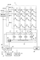
- FIG. 2 is a block diagram showing an equivalent circuit of the radiation image capturing apparatus.
- a plurality of radiation detection elements 7 are arranged in a two-dimensional shape (matrix shape) on a sensor substrate (not shown). Each radiation detection element 7 generates a charge according to the dose of the irradiated radiation.
- a bias line 9 is connected to each radiation detection element 7, and the bias line 9 is connected to a connection 10.
- the connection 10 is connected to a bias power supply 14 so that a reverse bias voltage is applied from the bias power supply 14 to each radiation detection element 7 via the bias line 9 and the like.
- a thin film transistor (hereinafter referred to as TFT) 8 is connected to each radiation detection element 7 as a switch element, and the TFT 8 is connected to the signal line 6.
- the scanning drive means 15 the on voltage and the off voltage supplied from the power supply circuit 15a via the wiring 15c are switched by the gate driver 15b and applied to the lines L1 to Lx of the scanning line 5. Yes.
- each TFT 8 is turned on when an on-voltage is applied via the scanning line 5, discharges the charge accumulated in the radiation detection element 7 to the signal line 6, and also passes through the scanning line 5.
- the off voltage is applied, the radiation state is turned off, the conduction between the radiation detection element 7 and the signal line 6 is interrupted, and the charge generated in the radiation detection element 7 is accumulated in the radiation detection element 7. It has become.
- a plurality of readout circuits 17 are provided in the readout IC 16, and the signal lines 6 are connected to the readout circuits 17, respectively.
- the amplification circuit 18 corresponds to the amount of the charged charge. Output voltage value.
- the correlated double sampling circuit (described as “CDS” in FIG. 2) 19 reads out the voltage value output from the amplifier circuit 18 as analog image data D and outputs it to the downstream side.
- the output image data D is sequentially transmitted to the A / D converter 20 via the analog multiplexer 21, and is sequentially converted into digital image data D by the A / D converter 20, and is output to the storage means 23. Are stored sequentially.
- the control means 22 is a CPU (Central Processing Unit), a ROM (Read Only Memory), a RAM (Random Access Memory), a RAM (Random Access Memory), an input / output interface connected to the bus, an FPGA (Field Programmable Gate Array) or the like. It is configured. It may be configured by a dedicated control circuit.
- the control means 22 is connected to a storage means 23 composed of SRAM (Static RAM), SDRAM (Synchronous DRAM), NAND flash memory or the like.
- a communication unit 30 that performs communication by a wired method is connected.
- control means 22 is connected to a built-in power supply 24 for supplying necessary power to each functional unit such as the scanning drive means 15, the readout circuit 17, the storage means 23, and the bias power supply 14.
- the control means 22 controls the operations of the scanning drive means 15 and the readout circuit 17 as described above during the reading process of the image data D, and is emitted from each radiation detection element 7 to the signal line 6. Control is performed so that the read charges are read out as image data D by the readout circuit 17 or the like.
- the radiographic image capturing apparatus 1 can be mounted on an imaging stand (not shown) and used for imaging, the illustration is omitted.
- it can be applied to the body of a patient as a subject, or can be used for photographing by being inserted between a patient and a bed, for example.
- the control means 22 uses, as the shooting mode, a still image mode for performing still image shooting, a moving image mode for performing moving image shooting, and image data D for each frame without distinguishing between still image shooting and moving image shooting.
- a continuous shooting mode in which the reading process is continuously performed in a plurality of frames.
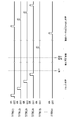
- the control unit 22 performs imaging in cooperation with a radiation irradiation device (not shown), for example. That is, as shown in FIG. 3, an on-voltage is sequentially applied to each of the lines L1 to Lx of the scanning line 5 from the gate driver 15b (see FIG. 2) of the scanning driving means 15, and the charge remaining in the radiation detecting element 7 Is reset to the radiation detection element 7 that is removed from the radiation detection element 7 by, for example, emitting the signal to the signal line 6.
- the control means 22 of the radiation image capturing apparatus 1 is as shown in FIG.
- the reset process of the radiation detecting element 7 performed at that time is finished when the ON voltage is applied up to the final line Lx of the scanning line 5, and each line L 1 to Lx of the scanning line 5 is output from the gate driver 15 b.
- the off voltage is applied to the charge accumulation state to shift to the charge accumulation state.
- an interlock release signal is transmitted to the radiation irradiation apparatus.
- the radiation irradiating device irradiates the radiation when receiving the interlock signal from the radiation image capturing device 1.
- the hatched portion in FIG. 3 represents a period during which radiation is applied.
- the control means 22 of the radiographic image capturing apparatus 1 sequentially applies on-voltages to the lines L1 to Lx of the scanning line 5 from the gate driver 15b when a predetermined time has elapsed since the transition to the charge accumulation state. Then, the image data D is read out as described above.
- the radiation imaging device 1 In the still image mode, usually, before or after imaging, the radiation imaging device 1 is not irradiated with radiation, and the radiation detection element 7 is reset as shown in FIG. After that, when a predetermined time elapses, the offset data O reading process is performed in the same manner as the image data D reading process.
- the photographing mode is the still image mode
- photographing may be performed in a state where the radiation image photographing apparatus 1 and the radiation irradiation apparatus are not linked as described above.
- the radiographic imaging apparatus 1 it is necessary for the radiographic imaging apparatus 1 to detect that radiation irradiation has started.
- the radiographic imaging apparatus 1 is configured to include an X-ray sensor (not shown), and the control unit 22 detects the start of radiation irradiation based on the output value from the X-ray sensor. Can be configured.
- control unit 22 when the control unit 22 is configured to detect the start of radiation irradiation based on the output value from the X-ray sensor, the control unit 22 is configured to detect the radiation detection element 7 before the start of radiation irradiation, as shown in FIG. Perform the reset process. Then, when the start of radiation irradiation is detected based on the output value from the X-ray sensor, the reset processing of the radiation detection element 7 is stopped at that time to shift to the charge accumulation state.
- the on-voltage is sequentially applied from the gate driver 15b to each of the lines L1 to Lx of the scanning line 5 to read out the image data D as described above. Configured to do. In this case as well, offset data O is normally read out before or after shooting.
- the control unit 22 of the radiographic image capturing apparatus 1 when the image capturing mode is the moving image mode, captures an image capturing situation in which moving image capturing is performed (whether dynamic image capturing, tomosynthesis image capturing, other image capturing, or radiation irradiation is pulsed)
- the image data D is read out in a continuous manner, in accordance with the irradiation time or number of irradiations, the time interval from irradiation to the next irradiation, or the like.
- the control means 22 of the radiographic image capturing apparatus 1 synchronizes with the timing of radiation irradiation from the radiation irradiation apparatus, for example, as shown in FIG. 5, the radiation irradiation (see the hatched portion in the figure) and the next The image data D is read out during irradiation with radiation. That is, the reading process of the image data D is performed for each frame.
- the offset data O is not normally read out, and shooting is performed one after another for each frame.
- the offset data O may be read out for each frame.
- the offset data O is not normally read out between the irradiation of radiation and the irradiation of the next radiation. And done.
- the offset data O may be read out for each frame. Further, there is a case where the offset data O for one frame or a plurality of frames is read out before and after a series of pulsed radiation irradiation or continuous irradiation with a low dose of radiation.
- the read image data D may be configured to be transferred to an external image processing apparatus or the like for each imaging (that is, for each frame), and the storage unit 23 ( It is also possible to store the image data in the image processing apparatus or the like later, and this is the same as in the still image mode.
- the control unit 22 of the radiographic image capturing apparatus 1 sets the image data as a capturing mode regardless of whether still image capturing or moving image capturing is performed without distinguishing between still image capturing and moving image capturing. It has a continuous shooting mode in which D can be read. As described above, in the still image mode and the moving image mode, the control unit 22 needs to perform the reading process of the image data D while synchronizing with the radiation irradiation apparatus.
- control means 22 does not distinguish between still image shooting and moving image shooting, and does not perform processing such as synchronization with the radiation irradiation apparatus.
- Control is performed so that the reading process of the image data D for each frame is repeatedly performed continuously in a plurality of frames.
- the frame (or one frame) refers to a period in which the ON voltage is sequentially applied from the first line L1 to the last line Lx of the scanning line 5 from the gate driver 15b (see FIG. 2) of the scanning driving unit 15.
- control mode 22 is set to the continuous radiographing mode as described above. It is possible to configure to start the reading process of the image data D for each frame from the time point set to.
- the control means is used to avoid the consumption of the built-in power supply 24 (see FIG. 2). 22 when the imaging mode is set to the continuous imaging mode, the radiographic imaging apparatus 1 first uses an X-ray sensor or the like as in the case where the radiographic imaging apparatus 1 and the radiation irradiation apparatus do not cooperate with each other. It is also possible to start the detection process for detecting the start of radiation irradiation by itself and shift to the process of repeatedly reading the image data D for each frame when the start of radiation irradiation is detected.
- the shooting mode when the shooting mode is set to the continuous shooting mode, the method of starting the reading process of the image data D for each frame immediately after that point and the shooting mode are set to the continuous shooting mode. At that time, the process of starting the radiation irradiation start detection process is started, and at the time when the radiation irradiation start is detected, one of the processing methods to shift to the reading process of the image data D for each frame is performed. It is also possible to configure so that the operator can set or select.
- the control means 22 of the radiographic imaging apparatus 1 is such that an operator (user) such as a radiographer operates the changeover switch 26 (see FIG. 1) of the radiographic imaging apparatus 1 or a console or the like.
- An instruction to perform still image shooting or moving image shooting to the radiographic image capturing device 1 by operating a control device outside the control unit and transmitting a signal from the control device to the radiographic image capturing device 1. If there is, the control means 22 of the radiographic image capturing apparatus 1 sets the radiographing mode of the radiographic image capturing apparatus 1 to a mode corresponding to the instructed imaging (that is, in response to an instruction to perform still image capturing) Set to still image mode or movie mode for instructions to shoot movies.
- control unit 22 performs imaging corresponding to the set imaging mode as described above, and in the case of still image shooting, reads out the image data D for one radiation image, and captures a moving image. In this case, the image data D for a plurality of sheets is read out.
- the radiographic imaging device 1 when there is no instruction to perform still image shooting or instruction to perform moving image shooting from an operator such as a radiographer or an external control device such as a console, If communication with an external control device cannot be performed and it is unclear whether shooting is still image shooting or movie shooting, the radiographic imaging device 1 is set to the continuous imaging mode. Thus, the reading process of the image data D for each frame is controlled to be performed continuously in a plurality of frames.
- an operator such as a radiographer does not input or transmit an instruction to perform still image shooting or an instruction to perform moving image shooting to the radiographic image capturing apparatus 1 directly or via a console or the like.
- the control means 22 of the radiographic image capturing apparatus 1 does not know whether the image capturing to be performed is still image capturing or moving image capturing.
- the control unit 22 does not select the still image mode or the moving image mode as the imaging mode of the radiographic image capturing apparatus 1, even if still image shooting is performed as described above.
- the continuous shooting mode in which the reading process of the image data D for each frame is repeatedly performed is set.
- the control means 22 of the radiographic image capturing apparatus 1 monitors the communication state in the communication unit 30 (see FIG. 2) at a predetermined timing. And under the situation where both still image shooting and movie shooting can be performed, the wireless communication environment such as the radio wave condition deteriorates so that wireless communication with the console cannot be performed, and the next shooting is stopped. Even when it is unclear whether it is image shooting or movie shooting, the control means 22 of the radiographic image capturing apparatus 1 sets the shooting mode to the continuous mode as described above, not the still image mode or the movie mode. Set to shooting mode.
- the control means 22 of the radiographic image capturing apparatus 1 sets the capturing mode to the continuous capturing mode when the apparatus is activated. That is, as described above, when the radiographic imaging apparatus 1 is activated, the control unit 22 causes each functional unit to perform a predetermined initial operation, and then starts reading processing of the image data D for each frame. Alternatively, it is configured to start detection processing of radiation irradiation (after that, reading processing of image data D for each frame is performed at the time of detection of irradiation start).
- the radiographic image capturing apparatus 1 or the radiation irradiation apparatus when brought into the patient's home or disaster scene to perform imaging, that is, without being controlled by an external control device such as a console.
- an external control device such as a console.
- the radio wave condition When taking a radiograph in a patient room or a patient's home, etc., for example, the radio wave condition will deteriorate and the communication will be interrupted. Thus, a case is assumed where the radiographic image capturing apparatus 1 can no longer communicate with the console or the like.
- the present invention can also be applied to a case where, for example, the radio communication environment is deteriorated and radio communication between the radiographic imaging apparatus 1 and the console cannot be performed even in a radio room with a radio environment. If there is no instruction to the radiographic image capturing apparatus 1 to shoot a still image or an instruction to shoot a moving image, or communication with an external control device such as a console cannot be performed.
- the present invention can be applied to any case as long as it is unclear whether it is still image shooting or moving image shooting.
- the control unit 22 of the radiographic image capturing apparatus 1 changes the radiographing mode of the radiographic image capturing apparatus 1 when there is an instruction to perform still image capturing or moving image capturing from an operator such as a radiographer.
- shooting mode is set to the continuous shooting mode.
- the control means 22 performs the gate driver of the scanning drive means 15 so as to repeatedly read out the image data D for each frame continuously in a plurality of the frames. 15b, the readout circuit 17 (see FIG. 2) and the like are controlled.
- the continuous shooting mode is set as the shooting mode. It is also possible to start the radiation irradiation start detection process at the set time and shift to the process of repeatedly performing the reading process of the image data D for each frame when the radiation irradiation start is detected. .
- the radiation irradiation time When still image shooting is performed while the radiographic image capturing apparatus 1 is in the continuous image capturing mode, the radiation irradiation time, the frame rate (the time required for the reading process of the image data D for one frame), etc.
- the frame rate the time required for the reading process of the image data D for one frame
- radiation irradiation may be performed over several frames.
- FIG. 8 although the case where irradiation of a radiation is performed over 2 frames is shown, it may be performed over 3 frames or more. Moreover, in FIG. 7, FIG. 8 and the following each figure, the shaded part represents the period during which radiation is applied.
- the radiographic image capturing apparatus 1 is in the continuous image capturing mode, the radiation image capturing apparatus 1 is irradiated with radiation through a subject (not shown) in both cases of FIGS.
- the reading process of the image data D is repeatedly performed in the radiation image capturing apparatus 1. Therefore, it is possible to accurately and surely read out the image data D including a component due to the electric charge generated in each radiation detection element 7 due to radiation irradiation.
- the radiation image capturing apparatus 1 is irradiated with pulses in the form of a pulse. Before the charge generated in step 1 is read out as image data D, the next pulsed radiation is applied, resulting in a so-called double exposure (multiple exposure) state.
- the radiographic image capturing apparatus 1 when the radiographic image capturing apparatus 1 is set to the continuous image capturing mode, it is set to the fastest frame rate that can be set by the radiographic image capturing apparatus 1 and the image data D is read out for each frame. It is desirable to configure.
- the radiation image capturing apparatus 1 when the radiation image capturing apparatus 1 is in the continuous capturing mode, for example, when moving image capturing is performed, when irradiation is performed in a state where a low dose of radiation is continuously irradiated, radiation irradiation is started. If it does, it will be in the state which continues to irradiate for a long period of time on the order of several seconds to several tens of seconds.
- the reading process of the image data D for each frame is repeatedly performed while the radiation is continuously applied. It becomes possible to accurately and surely read out the image data D including the component due to the charge generated in each radiation detection element 7.
- an instruction to perform still image shooting or an instruction to perform moving image shooting from an external control device such as a console or a user such as a radiographer. Even if there is no communication with the external control device, even if it is unclear whether the shooting is a still image shooting or a moving image shooting, the control means 22 of the radiographic image shooting device 1 performs the shooting.
- the mode is set to the continuous shooting mode, and control is performed so that the reading process of the image data D for each frame is repeated continuously in a plurality of frames.
- the image data D can be accurately read by the reading process of the image data D for each frame, and the still image is captured in the continuous shooting mode. Both shooting and movie shooting can be performed accurately.
- the control means 22 of the radiographic imaging device 1 switches the imaging mode of the radiographic imaging device 1 to the continuous imaging mode, an operator such as a radiographer does not always switch the imaging mode to the still image mode or the moving image mode. However, since still image shooting and moving image shooting can be performed accurately, the operator can freely perform shooting without performing troublesome work such as switching of shooting modes.
- the radiographic image capturing apparatus 1 is in the continuous image capturing mode, it is possible to perform still image capturing or moving image capturing as described above. For example, when performing still image capturing, It is possible to capture a radiographic image of a still image more accurately by shooting in a still image mode (see FIGS. 3 and 4) suitable for still image shooting than in still image shooting in continuous shooting mode. There are many cases.
- the radiographic image capturing apparatus 1 when the radiographic image capturing apparatus 1 is in the continuous imaging mode, an operator such as a radiographer performs imaging in the continuous imaging mode as it is, or switches the imaging mode to the still image mode or the moving image mode. In order to be able to make a determination, it is desirable to notify the operator that the radiographic image capturing apparatus 1 is in the continuous image capturing mode.
- the operation of the radiographer or the like is performed by causing the indicator 28 (see FIG. 1) of the radiographic imaging apparatus 1 to emit light in a predetermined color, lighting or blinking manner, or to generate a peep sound. It can be configured to notify the person.
- the operator has a smartphone, a portable information terminal, etc., it is also possible to transmit to them and display them on the screen or generate a sound to notify them. is there.
- the image data D can be transferred to an external device every time the image data D is read for each frame as described above in the continuous shooting mode.
- the radiographic image capturing apparatus 1 is connected to a network such as the Internet via a wireless LAN or the like, and the radiographic image capturing apparatus 1 reads the image data D for each frame as described above. It is possible to transfer the image data D to an external device such as a server on the cloud or a system connected to the network, and store and store the image data D on the external device.
- the image data D read out for each frame in the continuous imaging mode in the storage unit 23 (see FIG. 2) of the radiographic image capturing apparatus 1 and store it.
- the discrimination processing is accurately performed using an external device such as a server on the cloud or the image data D for each frame stored in the storage unit 23 of the radiographic imaging device 1. Can be performed.
- dark charges are constantly generated in the radiation detection element 7 due to the heat (temperature) of the radiation detection element 7 of the radiation detection element 7 itself.
- dark charges emitted from each radiation detection element 7 are read out as image data D.
- the image data D read out at this time is when irradiation with radiation is performed. The value is much smaller than the image data D that includes a component caused by the charge generated in each radiation detection element 7 due to radiation irradiation.
- a threshold is set that can appropriately separate the image data D resulting from the dark charge and the image data D including the component caused by the charge generated in each radiation detection element 7 by radiation irradiation.
- the control means 22 of the radiographic image capturing apparatus 1 monitors the value of the image data D read from each radiation detection element 7, and the image data D of a frame from which the image data D equal to or higher than the threshold is not read is
- the configuration is such that the image data D of the frame is transferred or stored only when the image data D of the frame is discarded without being transferred or stored, and the image data D of the frame includes the threshold value or more. Is also possible.
- each image data D read by applying an ON voltage to a line L with the scanning line 5 is read for each line L of the scanning line 5.
- An average value or the like is calculated, and when the average value or the like is equal to or greater than a threshold value, it is determined that the image data D includes a component caused by charges generated in each radiation detection element 7 due to radiation irradiation. It is also possible to do.
- the control unit 22 of the radiographic image capturing apparatus 1 monitors the value of the image data D read by the reading process for each frame as described above, and the value of the read image data D is caused by the dark charge described above.
- the state of the level of the image data D that is, the state where the image data D less than the threshold value is continuously read
- a predetermined time set to about several seconds to several tens of seconds
- the imaging mode remains in the continuous imaging mode, for example, a state in which detection processing for starting radiation irradiation is performed (for example, detection based on the output value of the X-ray sensor)
- detection processing for starting radiation irradiation for example, detection based on the output value of the X-ray sensor
- the radiation detecting element 7 is subjected to reset processing or the like).
- the radiation irradiation time is about several seconds to several tens of seconds. Therefore, for example, the radiation irradiation start detection process started from the time when the shooting mode is set to the continuous shooting mode.
- a predetermined time (from several tens of seconds to about 1 minute) is transferred to the reading process of the image data D for each frame. It is also possible to configure so that the reading process of the image data D for each frame is stopped at the time when the setting) elapses.
- the reading process of the image data D for each frame is performed again. It is controlled so as to shift to a state where the process is repeated.
- the image data D for each frame captured in the state in which the radiographic image capturing apparatus 1 is in the continuous image capturing mode is the image data D by still image capturing or the image data D by moving image capturing.
- a discrimination process for discriminating whether or not is will be described.
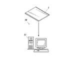
- the operation of the radiation image capturing system 50 (see FIG. 10) according to the present embodiment will also be described.
- the determination processing is performed by the image processing apparatus 51 such as a console.
- the control unit 22 of the radiographic image capturing apparatus 1 stores the image data D stored in the storage unit 23 or a server on the cloud. It is also possible to perform the discrimination processing based on the image data D obtained from the above. Further, the following determination processing may be performed after a series of imaging using the radiographic image capturing apparatus 1, or may be performed simultaneously with the imaging using the radiographic image capturing apparatus 1.
- the image processing apparatus 51 is composed of a general-purpose computer in which a CPU, ROM, RAM, input / output interface and the like (not shown) are connected to a bus, and system programs and processing programs stored in the ROM and the like. These various programs are read out and expanded in the RAM, and various processes are executed in accordance with the expanded programs. However, they may be configured as a dedicated device. In the present embodiment, it is assumed that the image processing apparatus 51 is a console, but it may be a separate apparatus from the console.
- the image processing device 51 reads the image data D for each frame read out when the imaging mode is the continuous imaging mode in the radiographic image capturing device 1 (as described above, each radiation by irradiation of radiation). Including the case of only the image data D of the frame including the image data D including the component due to the charge generated in the detection element 7) from an external device such as a server on the cloud described above, or As shown in FIG. 10, the image data D is obtained by transferring the image data D from the radiographic image capturing apparatus 1 stored in the storage unit 23 by a wired method or a wireless method.
- the image processing apparatus 51 performs the discrimination process as follows.
- the image processing apparatus 51 first determines the irradiation time during which radiation is irradiated on the radiographic image capturing apparatus 1 in the continuous imaging mode, based on the image data D read in the frame-by-frame reading process. An irradiation time is calculated. This will be specifically described below.
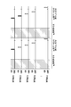
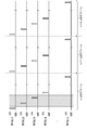
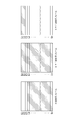
- FIG. 11 shows a component caused by charges generated in each radiation detection element 7 due to radiation when the radiation imaging apparatus 1 in the continuous imaging mode is irradiated with radiation as shown in FIG. 7, for example.
- each radiation detection element 7 connected to the line L ⁇ b> 1 of the scanning line 5 gives unnecessary image data D (image data less than the above threshold value) due to dark charges. D) Only read out.
- the line L2 of the scanning line 5 is connected to the line L2 of the scanning line 5 as shown in FIG.
- Useful image data D image data D equal to or higher than the above-described threshold value
- image data D equal to or higher than the above-described threshold value
- the image data D read from each radiation detection element 7 is also useful image data D including a component due to charges generated in each radiation detection element 7 due to radiation irradiation.
- the radiation detection elements 7 connected to the line L1 of the scanning line 5 receive radiation in the mth frame. Since the image data D including the component due to the charge generated in each radiation detection element 7 by irradiation has not been read out, such useful image data D is read out in the (m + 1) th frame.
- the lines L2 and L3 of the scanning line 5 are irradiated with radiation even after the application of the on-voltage in the m-th frame.
- Useful image data including a component due to the charge generated in each radiation detection element 7 by radiation irradiated after the application is completed is read out in the (m + 1) th frame. Therefore, as shown in FIG. 11, the image data D read from each radiation detection element 7 connected to the lines L2 and l3 of the scanning line 5 in the (m + 1) th frame is also useful image data D.
- the timing at which radiation irradiation is started is the time when useful image data D (that is, image data D that is equal to or greater than a threshold value) is read for the first time (that is, in the example of FIG. (When the on-voltage is applied to the line L2).
- the timing at which the irradiation of radiation is completed is one frame from the time when a useful image is finally read (that is, the time when the ON voltage is applied to the line L3 of the scanning line 5 in the m + 1th frame). This is the previous time point (ie, the time point at which the ON voltage is applied to the line L3 of the scanning line 5 in the m-th frame).
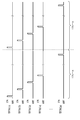
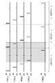
- useful image data including a component due to the charge generated in each radiation detection element 7 due to the radiation applied after the ON voltage is applied to the line L2 of the scanning line 5 in the (m + 1) th frame is the (m + 2) th time. Is read out in the next frame. Therefore, in this case, the range indicated by hatching in FIG. 12 is the range from which useful image data D is read.
- the timing at which radiation irradiation is started is the time when useful image data D (that is, image data D equal to or higher than the threshold value) is read for the first time, that is, the mth time. In this frame, the on-voltage is applied to the line L4 of the scanning line 5.
- the timing at which the irradiation of radiation is completed is one frame before the time when the useful image is finally read, that is, the time when the on-voltage is applied to the line L2 of the scanning line 5 in the m + 2th frame. It can be seen that this is the time when the on-voltage is applied to the line L2 of the scanning line 5 in the m + 1th frame. And this analysis result corresponds with the period when the radiation shown in FIG. 8 is irradiated.
- the image processing apparatus 51 uses the above analysis results (1) and (2) as a criterion to determine the radiation in the continuous imaging mode based on the image data D read in the reading process for each frame.
- An irradiation time T is calculated for calculating the irradiation time T from the start of irradiation of radiation to the image capturing apparatus 1 until the end of irradiation.
- T is the time from when the on-voltage is applied to the line L2 of the scanning line 5 in the m-th frame to when the on-voltage is applied to the line L3 of the scanning line 5 in the same m-th frame. This is calculated as the time required to read the image data D from each radiation detection element 7 connected to the two scanning lines 5 in the reading process of the image data D.
- the irradiation time T is the time from when the on-voltage is applied to the line L4 of the scanning line 5 in the m-th frame to when the on-voltage is applied to the line L2 of the scanning line 5 in the next m + 1th frame. Therefore, it is calculated as the time required to read out the image data D from each of the radiation detection elements 7 connected to the x ⁇ 1 scanning lines 5 in the reading process of the image data D.
- the image data D for each frame shot in the state in which the radiographic image capturing apparatus 1 is in the continuous image capturing mode is image data D by still image capturing or by moving image capturing. It may be possible to determine whether the image data is D. Therefore, in this embodiment, in such a case, the image processing device 51 determines whether the image data D for each frame is image data D obtained by still image shooting or image data obtained by moving image shooting based on the calculated irradiation time T. A discrimination process for discriminating whether it is D is performed.
- the image processing apparatus 51 determines that the image data D for each frame captured in the continuous imaging mode in the radiation image capturing apparatus 1 is the image data D obtained by moving image capturing.
- the image processing apparatus 51 uses the radiographic image capturing apparatus 1 to determine whether the image data D for each frame captured in the continuous capturing mode is the image data D for still image capturing or the image data D for moving image capturing. Can be determined based on the irradiation time T.
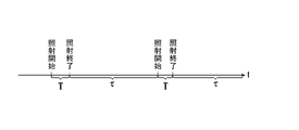
- the judgment criteria (1) and (2) described in the above-mentioned calculation of the irradiation time T are used, it is possible to determine the radiation irradiation start timing and the irradiation end timing. Then, by calculating the elapsed time from the radiation irradiation end timing to the next radiation irradiation start timing, the elapsed time ⁇ from the end of the radiation irradiation to the start of the next radiation irradiation is determined. be able to.
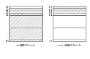
- the elapsed time ⁇ and the irradiation time T described above have a relationship as shown in FIG. 13.
- the irradiation time T is the time during which the radiation is irradiated
- the elapsed time ⁇ is the time after the irradiation. Each time before irradiation is shown.
- the elapsed time ⁇ from the end of radiation irradiation to the start of the next radiation irradiation takes several seconds at the earliest.
- Radiation is irradiated in pulses at short intervals such as several tens to several hundreds of milliseconds.
- the image processing device 51 is the image data D by still image shooting when the above-described elapsed time ⁇ is, for example, 1 second or more, and the image data D by moving image shooting when it is less than 1 second. It comes to discriminate.
- the time used as a criterion for discrimination can be set to an appropriate time such as 2 seconds instead of 1 second as described above.
- the above-mentioned elapsed time ⁇ between the image data D is several seconds or more, including when the image data D is image data D by still image shooting and when it is image data D by moving image shooting, It is determined that the picture is taken.
- a filter for reducing the dose of radiation to be irradiated may be disposed in the radiation irradiation device in order to reduce the dose rate DR.
- the dose rate DR of the radiation irradiated during the moving image shooting is usually compared with the dose rate DR of the radiation irradiated during the still image shooting. The value is much smaller. And the value of the image data D read from each radiation detection element 7 becomes large, so that the dose rate DR of the radiation irradiated to the radiographic imaging apparatus 1 is large.
- the image processing apparatus 51 calculates the dose rate DR of the radiation irradiated to the radiographic image capturing apparatus 1 from the value of the image data D read out for each frame as described above. Based on the radiation dose rate DR (that is, based on whether the calculated radiation dose rate DR is greater than or less than a threshold value), the image data D is image data obtained by still image photography or image obtained by moving image photography. The data is discriminated.
- the image processing apparatus 51 stores, for each radiographic image capturing apparatus 1, information on the conversion rate between the read image data D and the dose rate DR of the irradiated radiation in the storage unit. Have. Further, when the radiation dose rate DR is calculated based on the individual image data D, the image data D read out due to noise or the like becomes a large value, and the calculated radiation dose rate DR. May be calculated larger than the actual value.
- the radiation dose rate DR instead of calculating the radiation dose rate DR based on the individual image data D as described above, for example, the charge generated in each radiation detection element 7 due to radiation irradiation shown in FIGS.
- the average value or the like of the image data D in the range (see the hatched line in the figure) in which the useful image data D including the component resulting from it is read is calculated for each line L of the scanning line 5, and the calculated average value and the like It is also possible to calculate the radiation dose rate DR based on the above.
- the image data D is obtained by still image shooting based on the read value of the image data D itself or the average value thereof. It can also be configured to discriminate between image data and image data obtained by moving image shooting.
- the threshold value for the value of the image data D, the average value thereof, or the like corresponding to the threshold value for distinguishing whether the image data D is image data obtained by still image shooting or image data acquired by moving image shooting is set. It is configured in advance so as to determine whether the image data D is image data by still image shooting or image data by moving image shooting depending on whether it is greater than or less than the threshold.
- the image processing apparatus 51 may include all of the above-described methods, that is, all of the methods using the irradiation time T, the elapsed time ⁇ , the radiation dose rate DR, the value of the image data D itself (or the average value thereof), or the like. At least one method is used to determine whether the image data D is image data by still image shooting or image data by moving image shooting. With this configuration, it is possible to accurately determine whether the image data D is image data by still image shooting or image data by moving image shooting.
- a still image can be shot by irradiating a subject with a low dose of radiation continuously while shooting a movie while irradiating a relatively large dose rate of radiation at a certain point in time.
- moving image shooting is performed until the image data D is read by applying an on-voltage from the first line L1 of the scanning line 5 to a certain line L in the reading process of the image data D for each frame. From the line L next to the scanning line 5, the dose rate increases and still image shooting is performed.
- the image data D for still image shooting and the image data D for moving image shooting are mixed in the image data D for one frame.
- the still image is included in the image data D for one frame.
- Image data D obtained by shooting and image data D obtained by moving image shooting are mixed.
- the radiation dose rate (or image data) By configuring so that the image data D is image data by still image shooting or image data by moving image shooting based on D itself or an average value thereof, it becomes possible to accurately separate them.
- the image processing apparatus 51 determines that the image data D is image data obtained by still image shooting or image data obtained by moving image shooting as a result of the above determination processing, the image processing device 51 obtains the information (that is, image data or still image shooting by still image shooting).
- the information indicating whether the image data is captured) is attached to the image data D by writing it in the header of the image data D, for example.
- the image data D is a series of image data obtained by the same moving image shooting. Information indicating this is also attached and processed as one group.
- information indicating the shooting order may be attached, for example, by numbering the shooting order (that is, in time series). desirable.
- the control unit 22 of the radiographic imaging device 1 applies the image data D to each image data D as described above.
- Information indicating whether the image data D is image data by still image shooting or image data by moving image shooting is attached, or a plurality of image data D determined to be image data D by moving image shooting is the same moving image shooting.
- the image data D is transferred to a server on the cloud or the image processing apparatus 51 with information indicating that it is a series of obtained image data.
- the image data D is the image data obtained by still image capturing or moving image capturing as described above.
- the still image radiographic image is erroneously recognized as a moving image radiographic image. It is possible to accurately prevent the generation of a radiographic image by mistakenly recognizing a radiographic image of a moving image as a radiographic image of a still image.
- the radiation image capturing apparatus 1 accurately determines whether the image data D captured by the radiation image capturing apparatus 1 is image data by still image capturing or image data by moving image capturing, and based on the image data D, the radiographic image or moving image of the still image is captured.
- a plurality of radiation images can be appropriately generated.
- the image processing device 51 generates a radiographic image of a still image or a plurality of radiographic images of a moving image based on information attached to the image data D based on the result of the discrimination processing. Yes.
- the image processing apparatus 51 generates a radiographic image of a still image based on the image data D attached with information indicating that the image data is captured by still image, and represents that the image data is captured by moving image.
- a plurality of radiation images constituting a moving image are generated based on the image data D to which information is attached. This will be specifically described below.
- image data D by moving image shooting performed by irradiating pulsed radiation among image data D by still image shooting or image data D by moving image shooting.
- useful image data D including components due to charges generated in the radiation detection element 7 due to radiation irradiation may be read out in a plurality of frames.
- the charges generated in the radiation detection elements 7 connected to the lines L2 and L3 of the scanning line 5 are the images of the mth frame and the m + 1th frame, respectively. Read as data D.
- the image data D obtained by adding the mth frame, the m + 1th frame, and the read image data D is originally That is, the image data D to be read out.
- the image data D not only the charges generated in the radiation detection element 7 due to the irradiation of radiation but also offsets due to dark charges are superimposed.
- the image data D obtained by adding the mth frame and the m + 1th frame and the read image data D is used, and for the line L1 of the scanning line 5, the m + 1th time is used. If the image data D read in the first frame is used and the image data D read in the m-th frame is used for the lines L4 to Lx of the scanning line 5, the lines L2 and L3 of the scanning line 5 are used.
- the image data D read from the connected radiation detection element 7 the offset due to the dark charge is superimposed for two frames, whereas the other lines L1, L4 to S4 of the scanning line 5 are superimposed.
- the image data D read from the radiation detection element 7 connected to Lx is superimposed with the offset due to the dark charge for one frame. To become, unevenness in the generated radiation image is likely to occur.
- useful image data D including a component due to charges generated in the radiation detection element 7 due to radiation irradiation is read out in the m-th and m + 1-th two frames.
- the read image data D (including not only the hatched portion in FIG. 11 but also the image data D of the hatched portion) is added to calculate the image data D.
- useful image data D including components due to charges generated in the radiation detection element 7 due to radiation irradiation such as the lines L4 to Lx of the scanning line 5 in the m-th frame shown in FIG.
- useful image data D including components due to charges generated in the radiation detection element 7 due to radiation irradiation such as the lines L4 to Lx of the scanning line 5 in the m-th frame shown in FIG.
- the offset correction may be performed using the image data D of the line that is not read out as the offset data O of the corresponding line.
- the latest frame from which only unnecessary image data D due to dark charge is read is set as the offset data O, so that the latest frame is offset data because there is no charge accumulation state. O, and more accurate correction can be performed.
- the image data D obtained by adding the image data D read in the m-th frame and the m + 1-th frame is calculated.
- the offset due to the dark charge is superimposed for two frames, it is caused by the dark charge in the nearest frame such as the lines L2 and L3 of the scanning line 5 in the m + 2th frame shown in FIG.
- offset correction is performed by the added number of frames, so that the superimposed offset can be accurately corrected.
- the image data D obtained by adding the image data D is used, and the image data D read out in the m-th frame is used for the lines L4 to Lx of the scanning line 5, and the image data D of the image data D is corresponding to each line. Even when the number of additions is different, it is possible to cancel the offset due to the superimposed dark charge, and it is possible to suppress the occurrence of unevenness in the radiation image.
- the offset data O is added to the image data D of a line from which only unnecessary image data D due to dark charge is read out, for each frame of the correction target frame, for example, a plurality of frames. May be generated.
- the image processing device 51 performs known image processing such as gain correction and gradation processing on the image data D calculated as described above, and the still image radiation based on the image data D obtained by still image shooting. An image is generated, and a plurality of moving image radiation images are generated based on image data D obtained by moving image shooting.
- the radiation is continuously generated in each frame.
- the useful image data D including the component due to the charges generated in the radiation detection element 7 due to the irradiation is read out.
- it can be configured to generate a radiation image for each frame. That is, it can be configured to generate one radiation image for each frame.
- a moving image radiographic image a plurality of radiographic images corresponding to the number of frames from which useful image data D including components due to charges generated in the radiation detecting element 7 due to radiation irradiation are read out are included. Generated.
- image data D obtained by still image shooting and image data D obtained by moving image shooting are mixed in one frame of image data D as in the barium examination of the stomach and the like, as described above. Needless to say, the image data D obtained by shooting a still image and the image data D obtained by moving image shooting are processed separately.
- the image processing device 51 generates a radiographic image of a still image based on the image data D attached with information indicating that the image data is captured by still image, and the image captured by moving image capturing.
- the image data D By generating a plurality of radiation images constituting a moving image based on the image data D attached with information indicating that it is data, it is the image data D by still image shooting or by moving image shooting as described above.
- Based on the image data D that has been accurately determined whether it is the image data D it is possible to appropriately generate a radiographic image of a still image and a plurality of radiographic images of a moving image.
- the apparatus 51 has imaging order information in order to associate the generated radiographic image with corresponding imaging order information.
- the shooting order information specifies whether shooting is performed by still image shooting (also referred to as simple shooting or general shooting) or moving image shooting.
- the image data D for each frame captured by the radiographic image capturing device 1 in the continuous capturing mode is arranged in order of capturing (in time series), and By associating with the shooting order information arranged in the shooting order, it can be configured to determine whether the image data D is image data D by still image shooting or image data D by moving image shooting. .
- the determination process can be performed using the shooting order information.
- control means 22 of the radiographic imaging device 1 repeats the reading process of the image data D every frame as shown in FIG. 6 when the radiographic imaging device 1 is set to the continuous imaging mode.
- the read image data D for each frame is stored in the storage means 23 (see FIG. 2).
- an operator such as a radiographer directly operates the radiographic image capturing apparatus 1 or operates a smartphone, a portable information terminal, or the like, and based on the read image data D for each frame, an image obtained by moving image capturing.
- the control unit 22 of the radiographic image capturing apparatus 1 reads the image data D for each frame from the storage unit 23, and based on these, the image data D by moving image capturing is read out.
- the control means 22 of the radiographic imaging device 1 receives a moving image from an operator such as a radiographer.
- image data D by shooting is input, for example, image data D by still image shooting is created one frame at a time, or every predetermined number of frames from consecutive frames
- the image data D for one frame is extracted respectively, and these are created as image data D for a plurality of frames by moving image shooting.
- the control means 22 of the radiographic image shooting apparatus 1 may, for example, The thinned data (or the image data D of all the frames) obtained by extracting the image data D for one frame every predetermined number of frames is transmitted to the portable information terminal or the like, and the thinned data is displayed on the display unit of the portable information terminal or the like. (Or all data) is displayed.
- the image data D for each frame having a predetermined number of frames, such as 2 frames and 3 frames including the frame of the frame number, is added for each pixel, and the image data D for one frame by still image shooting is created. It is possible.
- the control means 22 of the radiographic image capturing apparatus 1 receives image data obtained by moving image capturing from an operator such as a radiographer.
- image data D obtained by moving image capturing from an operator such as a radiographer.
- useful image data D including a component due to charges generated in the radiation detection element 7 due to radiation irradiation is obtained.
- Image data D for a plurality of frames by moving image shooting is created by adding the image data D of the read frames, respectively.
- the control means 22 of the radiographic image shooting device 1 takes a moving image shooting in the same manner as described above.
- a plurality of frames of image data D are created, transmitted to a portable information terminal or the like, displayed on the display unit, and the image data D of the frame selected by the operator from the frames is captured by one frame It is also possible to configure so as to create image data D for the minute.
- the image data D for every frame (so-called raw data) before the addition, or the image data D for one frame for every predetermined number of frames from the continuous frames.
- 11 for each frame including the frame of the frame number instructed by the operator who viewed the data by transmitting the thinned data (thinned raw data) extracted from the data to a portable information terminal or the like and displaying it on the display unit.
- the processing shown in FIG. 12 may be performed, and the image data D for each frame may be added to create image data D for one frame by still image shooting.
- the image processing apparatus 51 receives the image data D for one frame by the still image shooting created by the radiographic image capturing apparatus 1 from the radiographic image capturing apparatus 1. Based on this, a radiographic image of a still image is generated as described above. Further, when image data D for a plurality of frames created by the moving image capturing created by the radiation image capturing apparatus 1 is transmitted from the radiation image capturing apparatus 1, a plurality of radiation images constituting the moving image are generated based on them. Configured.
- an operator such as a radiographer takes a picture in a continuous shooting mode without intention of a still image or a moving image at the time of shooting, and is shot later. It is possible to configure to generate a still image or a moving image based on the image data D for each frame. Therefore, it is possible to improve the degree of freedom of imaging, and the radiographic image capturing apparatus 1 and the radiographic image capturing system 50 are easy to use for an operator such as a radiographer.
- the image processing device 51 can be configured to generate a still image or a moving image in accordance with an instruction from an operator such as the above-mentioned radiographer.
- the image data D for each frame read in the continuous imaging mode is transferred from the radiation imaging apparatus 1 to the image processing apparatus 51 via a server on the cloud or an external apparatus, or
- the image data D for each frame stored in the storage unit 23 of the radiation image capturing apparatus 1 is transferred from the radiation image capturing apparatus 1 to the image processing apparatus 51 after capturing.
- the image processing device 51 performs frame reading by the radiographic imaging device 1 in the continuous imaging mode in the same manner as the radiographic imaging device 1 described above in response to an instruction from an operator such as a radiographer.
- the image data D for one frame by still image shooting or the image data D for a plurality of frames by moving image shooting is created based on the image data D of the still image, and the still image is created based on the created image data D for one frame by still image shooting.
- a radiographic image of the image is generated, or a plurality of radiographic images constituting the moving image are generated based on the created image data D for a plurality of frames by moving image capturing.
- Imaging is performed by setting the imaging mode of the radiation image capturing apparatus 1 to the continuous imaging mode. If communication with an external apparatus cannot be performed in this way, there may be a case where image data D for each frame cannot be transferred from the radiation image capturing apparatus 1 to a server on the cloud.
- the image data D for each frame that could not be transmitted is temporarily stored in the storage unit 23 of the radiation image capturing apparatus 1, and the transfer of the image data D for each frame is resumed when communication is restored. Can be configured to. At that time, it is also possible to restart the transfer of the image data D from the frame subsequent to the frame in which the image data D for each frame is transferred immediately before the communication is interrupted.
- the image data D of the frame having the frame number “5” is read from the storage unit 23 and transferred, and the image data D of the frame having the frame number “7” is stored in the storage unit 23.
- the reading and storing of the image data D from the storage unit 23 are repeatedly performed at the same time, and the processing may be complicated.
- the image data D that cannot be transferred and stored in the storage unit 23 is stored in the storage unit 23 as it is even when communication is resumed, and is read out when the communication is restored.
- Each image data D is transferred first. It is also possible to transfer the image data D for each frame stored in the storage unit 23 when the transfer of the image data D for each frame is completed.
- the order of the image data D transferred to the image processing device 51 is such that the frame numbers “1”, “2”, “3”, “6”,. After the image data D for each frame, the image data D for each frame with frame numbers “4” and “5” is transferred, and the transfer order of the image data D to the image processing device 51 is captured. The order will be different from the order.
- At least the control unit 22 of the radiographic image capturing apparatus 1 applies to each frame from which the image data D is read out in a state in which the capturing mode is set to the continuous capturing mode.
- the image processing apparatus 51 can rearrange and transfer the image data D for each transferred frame to the frame number attached to the image data D (that is, the shooting order). It becomes.
- the image processing device 51 can perform processing by rearranging the transferred image data D for each frame in the order of shooting.
- the transfer order of the image data D for each frame to the image processing apparatus 51 is the imaging order of the image data D for each frame in the radiographic image capturing apparatus 1. Even in the case of different orders, it is possible to appropriately rearrange the image data D for each frame in the order in which the images were taken, and to accurately perform each process such as a discrimination process and a radiation image generation process. Become.
- the radiographic image capturing apparatus 1 is an apparatus having the storage unit 23 and the built-in power supply 24 as shown in FIG. 2, when the capturing mode is set to the continuous capturing mode as described above, If the reading process of the image data D is continuously repeated, the number of frames that can be captured is limited depending on the remaining amount of memory in the storage unit 23 and the remaining amount of the built-in power supply 24. There may occur a situation in which moving image shooting in which image data D for a large number of frames has to be read for generation cannot be performed.
- image data D having the number of frames necessary to generate 10 or 20 radiation images must be acquired. Further, the image data D having a larger number of frames is required.
- the control means 22 of the radiographic image capturing apparatus 1 monitors the remaining memory capacity of the storage means 23 and the remaining capacity of the built-in power supply 24, and when the remaining capacity falls below a predetermined amount, the information is, for example,
- the indicator 28 (see FIG. 1) can be configured to notify an operator such as a radiologist by emitting light in a predetermined color, lighting or flashing manner, or generating a peep sound. It is.
- the operator has a smartphone, a portable information terminal, etc., it is also possible to transmit to them and display them on the screen or generate a sound to notify them. is there.
- the remaining amount of memory in the storage unit 23 and the remaining amount of the built-in power supply 24, the power required for reading the image data D for one frame, the memory capacity of the storage unit 23 for storing it, and the image data for one frame Determine the number of frames that can be shot based on the power required to read D, for example, how many seconds can be taken in continuous shooting mode, whether dynamic shooting or tomosynthesis shooting is possible It is also possible to determine such information and notify the information by lighting, blinking, or beeping the indicator 28, or notifying with a smartphone or the like.
- the storage means 23 for storing the image data D is preferably a non-volatile storage medium in the continuous shooting mode or when communication with an external control device cannot be performed. Furthermore, it is preferable that this non-volatile storage medium is detachable from the radiation image capturing apparatus 1.
- the storage unit 23 is a non-volatile storage medium that can be attached to and detached from the radiation image capturing apparatus 1, so that even when communication with an external control device cannot be performed, the storage unit 23 can capture the radiation image. By detaching from the apparatus 1 and connecting to another external apparatus, the image data D stored in the storage means 23 can be easily read out.
- the image data D of two radiation images is usually captured at very short time intervals. Therefore, in the radiographic image capturing apparatus 1 according to the present embodiment, it is possible to perform imaging while setting the imaging mode to the moving image mode, and it is possible to perform imaging even when the imaging mode is set to the continuous imaging mode. It becomes possible.
- It may be used in the field of radiographic imaging (especially in the medical field).
Landscapes
- Health & Medical Sciences (AREA)
- Life Sciences & Earth Sciences (AREA)
- Engineering & Computer Science (AREA)
- Medical Informatics (AREA)
- Physics & Mathematics (AREA)
- Heart & Thoracic Surgery (AREA)
- General Health & Medical Sciences (AREA)
- Nuclear Medicine, Radiotherapy & Molecular Imaging (AREA)
- Optics & Photonics (AREA)
- Pathology (AREA)
- Radiology & Medical Imaging (AREA)
- Biomedical Technology (AREA)
- Biophysics (AREA)
- Molecular Biology (AREA)
- Surgery (AREA)
- Animal Behavior & Ethology (AREA)
- High Energy & Nuclear Physics (AREA)
- Public Health (AREA)
- Veterinary Medicine (AREA)
- Multimedia (AREA)
- Signal Processing (AREA)
- Human Computer Interaction (AREA)
- Mathematical Physics (AREA)
- Computer Vision & Pattern Recognition (AREA)
- Apparatus For Radiation Diagnosis (AREA)
- Measurement Of Radiation (AREA)
- Transforming Light Signals Into Electric Signals (AREA)
Abstract
L'invention concerne un appareil d'imagerie radiographique susceptible de capturer soit des images fixes soit une image animée, même lorsqu'aucune instruction pour une imagerie par image fixe ou une imagerie par image animée n'est donnée par un dispositif de commande externe ou un utilisateur ou lorsqu'on ne sait pas s'il faut réaliser une imagerie par image fixe ou une imagerie par image animée du fait de l'échec de l'établissement d'une communication avec le dispositif de commande externe. L'appareil d'imagerie radiographique (1) comprend un moyen de commande (22) qui a un mode d'imagerie en continu dans lequel des données d'image peuvent être lues, que l'on exécute une imagerie par image fixe ou une imagerie par image animée en tant que mode d'imagerie. Lorsqu'aucune instruction pour une imagerie par image fixe ou une imagerie par image animée n'est donnée par le dispositif de commande externe ou un utilisateur ou lorsqu'on ne sait pas s'il faut réaliser une imagerie par image fixe ou une imagerie par image animée du fait de l'échec de l'établissement d'une communication avec le dispositif de commande externe, le moyen de commande (22) effectue une commande de sorte que le mode d'imagerie en continu soit réglé comme mode d'imagerie afin d'effectuer en continu le traitement de lecture des données d'image (D) pour chaque trame parmi une pluralité de trames.
Priority Applications (1)
| Application Number | Priority Date | Filing Date | Title |
|---|---|---|---|
| JP2017529469A JP6662385B2 (ja) | 2015-07-17 | 2016-03-11 | 放射線画像撮影装置および放射線画像撮影システム |
Applications Claiming Priority (2)
| Application Number | Priority Date | Filing Date | Title |
|---|---|---|---|
| JP2015142809 | 2015-07-17 | ||
| JP2015-142809 | 2015-07-17 |
Publications (1)
| Publication Number | Publication Date |
|---|---|
| WO2017013896A1 true WO2017013896A1 (fr) | 2017-01-26 |
Family
ID=56404034
Family Applications (1)
| Application Number | Title | Priority Date | Filing Date |
|---|---|---|---|
| PCT/JP2016/057708 Ceased WO2017013896A1 (fr) | 2015-07-17 | 2016-03-11 | Appareil et système d'imagerie radiographique |
Country Status (4)
| Country | Link |
|---|---|
| US (1) | US10206647B2 (fr) |
| EP (1) | EP3123941B1 (fr) |
| JP (1) | JP6662385B2 (fr) |
| WO (1) | WO2017013896A1 (fr) |
Cited By (1)
| Publication number | Priority date | Publication date | Assignee | Title |
|---|---|---|---|---|
| JP2018175255A (ja) * | 2017-04-10 | 2018-11-15 | キヤノン株式会社 | 放射線撮影システム、放射線撮影装置、放射線撮影方法およびプログラム |
Families Citing this family (13)
| Publication number | Priority date | Publication date | Assignee | Title |
|---|---|---|---|---|
| US10416323B2 (en) * | 2016-03-29 | 2019-09-17 | Canon Kabushiki Kaisha | Radiation imaging apparatus, radiation imaging system, and method of operating radiation imaging apparatus |
| JP6763186B2 (ja) * | 2016-04-08 | 2020-09-30 | コニカミノルタ株式会社 | 放射線画像撮影システム |
| JP2018014555A (ja) * | 2016-07-19 | 2018-01-25 | 東芝電子管デバイス株式会社 | 放射線検出器、および放射線画像撮影装置 |
| JP7071095B2 (ja) * | 2017-11-15 | 2022-05-18 | キヤノン株式会社 | 放射線撮像装置 |
| CN108120729B (zh) * | 2017-12-28 | 2024-04-02 | 清华大学 | Ct检查系统和ct成像方法 |
| JP2019126523A (ja) * | 2018-01-24 | 2019-08-01 | コニカミノルタ株式会社 | 放射線撮影装置及び放射線撮影システム |
| JP7087435B2 (ja) * | 2018-02-19 | 2022-06-21 | コニカミノルタ株式会社 | 放射線画像撮影装置及び放射線画像撮影システム |
| DE102018219878B3 (de) * | 2018-11-20 | 2020-02-27 | Siemens Healthcare Gmbh | Steuereinheit für eine medizinische Bildgebungsanlage mit einem Prozessor und einem Logikgatter; Bildgebungsanlage sowie Verfahren zum Steuern einer medizinischen Bildgebungsanlage |
| JP7292952B2 (ja) * | 2019-04-25 | 2023-06-19 | キヤノン株式会社 | 放射線撮影システム、照射制御装置及び放射線撮影システムの制御方法 |
| CN115397332A (zh) * | 2020-02-11 | 2022-11-25 | 深透医疗公司 | 用于实时视频增强的系统和方法 |
| JP6860113B1 (ja) | 2020-08-19 | 2021-04-14 | コニカミノルタ株式会社 | 撮影制御装置、画像管理装置、画像管理システム及びプログラム |
| KR102513754B1 (ko) * | 2020-09-10 | 2023-03-27 | 주식회사 일렉필드퓨처 | 엑스레이장치 |
| US12381738B2 (en) * | 2023-04-20 | 2025-08-05 | HashiCorp | Zero-trust multi-hop authentication and authorization |
Citations (3)
| Publication number | Priority date | Publication date | Assignee | Title |
|---|---|---|---|---|
| WO2013015350A1 (fr) * | 2011-07-26 | 2013-01-31 | 富士フイルム株式会社 | Dispositif d'imagerie radiologique et procédé de commande de celui-ci et dispositif de détection d'image radiologique |
| WO2013015266A1 (fr) * | 2011-07-26 | 2013-01-31 | 富士フイルム株式会社 | Dispositif de détection de radiographies et son mode de fonctionnement |
| JP2014502914A (ja) * | 2011-01-21 | 2014-02-06 | ゼネラル・エレクトリック・カンパニイ | X線画像データを作成するためのx線システム及び方法 |
Family Cites Families (14)
| Publication number | Priority date | Publication date | Assignee | Title |
|---|---|---|---|---|
| JP4404291B2 (ja) | 2003-04-08 | 2010-01-27 | キヤノン株式会社 | 画像処理装置及び方法及びシステム |
| JPWO2006101230A1 (ja) * | 2005-03-25 | 2008-09-04 | コニカミノルタエムジー株式会社 | 放射線画像取得システム、カセッテ、コンソール、放射線画像通信システム及びプログラム |
| JP5224726B2 (ja) * | 2006-07-10 | 2013-07-03 | キヤノン株式会社 | 放射線画像撮影装置及びその制御方法 |
| JP5300216B2 (ja) * | 2006-08-29 | 2013-09-25 | キヤノン株式会社 | 電子カセッテ型放射線検出装置 |
| JP5136562B2 (ja) | 2008-01-15 | 2013-02-06 | コニカミノルタエムジー株式会社 | 動態画像診断支援システム |
| JP2009219538A (ja) | 2008-03-13 | 2009-10-01 | Konica Minolta Medical & Graphic Inc | 放射線画像検出装置および放射線画像撮影システム |
| JP2010022752A (ja) * | 2008-07-24 | 2010-02-04 | Konica Minolta Medical & Graphic Inc | 医用画像システム |
| JP5538694B2 (ja) * | 2008-08-28 | 2014-07-02 | キヤノン株式会社 | 放射線画像撮影装置及びその制御方法 |
| JP5737286B2 (ja) | 2010-04-30 | 2015-06-17 | コニカミノルタ株式会社 | 放射線画像撮影装置 |
| JP2011235006A (ja) | 2010-05-13 | 2011-11-24 | Fujifilm Corp | 放射線撮影装置及び方法 |
| US8785876B2 (en) | 2010-06-03 | 2014-07-22 | Konica Minolta Medical & Graphic, Inc. | Radiation image capturing apparatus |
| JP2011255020A (ja) * | 2010-06-10 | 2011-12-22 | Fujifilm Corp | 放射線撮影装置及び方法 |
| JP5902186B2 (ja) * | 2011-09-29 | 2016-04-13 | 富士フイルム株式会社 | 放射線撮影システム及び放射線撮影方法 |
| US9737271B2 (en) * | 2014-04-09 | 2017-08-22 | Canon Kabushiki Kaisha | Radiation imaging apparatus and control method of the same |
-
2016
- 2016-03-11 WO PCT/JP2016/057708 patent/WO2017013896A1/fr not_active Ceased
- 2016-03-11 JP JP2017529469A patent/JP6662385B2/ja not_active Expired - Fee Related
- 2016-07-11 EP EP16178828.6A patent/EP3123941B1/fr not_active Not-in-force
- 2016-07-12 US US15/207,890 patent/US10206647B2/en not_active Expired - Fee Related
Patent Citations (3)
| Publication number | Priority date | Publication date | Assignee | Title |
|---|---|---|---|---|
| JP2014502914A (ja) * | 2011-01-21 | 2014-02-06 | ゼネラル・エレクトリック・カンパニイ | X線画像データを作成するためのx線システム及び方法 |
| WO2013015350A1 (fr) * | 2011-07-26 | 2013-01-31 | 富士フイルム株式会社 | Dispositif d'imagerie radiologique et procédé de commande de celui-ci et dispositif de détection d'image radiologique |
| WO2013015266A1 (fr) * | 2011-07-26 | 2013-01-31 | 富士フイルム株式会社 | Dispositif de détection de radiographies et son mode de fonctionnement |
Cited By (1)
| Publication number | Priority date | Publication date | Assignee | Title |
|---|---|---|---|---|
| JP2018175255A (ja) * | 2017-04-10 | 2018-11-15 | キヤノン株式会社 | 放射線撮影システム、放射線撮影装置、放射線撮影方法およびプログラム |
Also Published As
| Publication number | Publication date |
|---|---|
| US10206647B2 (en) | 2019-02-19 |
| EP3123941B1 (fr) | 2018-02-28 |
| JP6662385B2 (ja) | 2020-03-11 |
| EP3123941A1 (fr) | 2017-02-01 |
| JPWO2017013896A1 (ja) | 2018-04-26 |
| US20170014094A1 (en) | 2017-01-19 |
Similar Documents
| Publication | Publication Date | Title |
|---|---|---|
| JP6662385B2 (ja) | 放射線画像撮影装置および放射線画像撮影システム | |
| JP5460103B2 (ja) | 放射線撮影装置及びその暗電流補正方法 | |
| US8894280B2 (en) | Calibration and correction procedures for digital radiography detectors supporting multiple capture modes, methods and systems for same | |
| CN104582574B (zh) | 电子式放射线摄影系统及信号中继装置 | |
| CN102188257B (zh) | 放射线照相图像获取装置、放射线照相图像捕获系统和方法 | |
| EP1734405A3 (fr) | Appareil d'imagerie radiographique, procédé de contrôle correspondant et système d'imagerie radiographique | |
| JP2013104826A (ja) | 放射線画像検出装置及び放射線撮影システム | |
| JP2007082907A (ja) | 画像撮影装置及び画像撮影方法 | |
| JP2018149047A (ja) | 放射線画像撮影システム | |
| JP4164644B2 (ja) | X線画像診断装置 | |
| JP7344769B2 (ja) | 放射線検出装置及び出力方法 | |
| JP6940929B2 (ja) | 放射線画像撮影システム | |
| JP2020048864A5 (ja) | 撮影制御装置、放射線画像撮影装置、放射線画像撮影システム及びプログラム | |
| JP6817750B2 (ja) | 放射線撮像装置、および放射線撮像装置の制御方法 | |
| JP6708032B2 (ja) | 放射線画像撮影システム | |
| JP6848407B2 (ja) | 放射線画像撮影システム | |
| JP6464699B2 (ja) | 放射線画像撮影システム | |
| JP6861512B2 (ja) | 放射線撮影装置およびその制御方法 | |
| JP2010274057A (ja) | 放射線撮影装置、放射線撮影方法及びプログラム | |
| JP2017113344A (ja) | 動態撮影装置及び動態撮影システム | |
| JPWO2016208229A1 (ja) | 放射線画像撮影装置および放射線画像撮影システム | |
| JP2004065635A (ja) | 画像処理装置 | |
| JP2016146513A (ja) | 診断提供用医用画像システム | |
| JP2026021843A (ja) | 放射線撮影制御装置、放射線撮影制御方法及びプログラム | |
| JP6638765B2 (ja) | 放射線画像撮影システム |
Legal Events
| Date | Code | Title | Description |
|---|---|---|---|
| 121 | Ep: the epo has been informed by wipo that ep was designated in this application |
Ref document number: 16827461 Country of ref document: EP Kind code of ref document: A1 |
|
| ENP | Entry into the national phase |
Ref document number: 2017529469 Country of ref document: JP Kind code of ref document: A |
|
| NENP | Non-entry into the national phase |
Ref country code: DE |
|
| 122 | Ep: pct application non-entry in european phase |
Ref document number: 16827461 Country of ref document: EP Kind code of ref document: A1 |