WO2017014129A1 - 経皮投与デバイス - Google Patents
経皮投与デバイス Download PDFInfo
- Publication number
- WO2017014129A1 WO2017014129A1 PCT/JP2016/070699 JP2016070699W WO2017014129A1 WO 2017014129 A1 WO2017014129 A1 WO 2017014129A1 JP 2016070699 W JP2016070699 W JP 2016070699W WO 2017014129 A1 WO2017014129 A1 WO 2017014129A1
- Authority
- WO
- WIPO (PCT)
- Prior art keywords
- administration device
- transdermal administration
- support substrate
- shape
- belt
- Prior art date
- Legal status (The legal status is an assumption and is not a legal conclusion. Google has not performed a legal analysis and makes no representation as to the accuracy of the status listed.)
- Ceased
Links
Images







Classifications
-
- A—HUMAN NECESSITIES
- A61—MEDICAL OR VETERINARY SCIENCE; HYGIENE
- A61M—DEVICES FOR INTRODUCING MEDIA INTO, OR ONTO, THE BODY; DEVICES FOR TRANSDUCING BODY MEDIA OR FOR TAKING MEDIA FROM THE BODY; DEVICES FOR PRODUCING OR ENDING SLEEP OR STUPOR
- A61M37/00—Other apparatus for introducing media into the body; Percutany, i.e. introducing medicines into the body by diffusion through the skin
- A61M37/0015—Other apparatus for introducing media into the body; Percutany, i.e. introducing medicines into the body by diffusion through the skin by using microneedles
-
- A—HUMAN NECESSITIES
- A61—MEDICAL OR VETERINARY SCIENCE; HYGIENE
- A61M—DEVICES FOR INTRODUCING MEDIA INTO, OR ONTO, THE BODY; DEVICES FOR TRANSDUCING BODY MEDIA OR FOR TAKING MEDIA FROM THE BODY; DEVICES FOR PRODUCING OR ENDING SLEEP OR STUPOR
- A61M37/00—Other apparatus for introducing media into the body; Percutany, i.e. introducing medicines into the body by diffusion through the skin
- A61M37/0015—Other apparatus for introducing media into the body; Percutany, i.e. introducing medicines into the body by diffusion through the skin by using microneedles
- A61M2037/0023—Drug applicators using microneedles
-
- A—HUMAN NECESSITIES
- A61—MEDICAL OR VETERINARY SCIENCE; HYGIENE
- A61M—DEVICES FOR INTRODUCING MEDIA INTO, OR ONTO, THE BODY; DEVICES FOR TRANSDUCING BODY MEDIA OR FOR TAKING MEDIA FROM THE BODY; DEVICES FOR PRODUCING OR ENDING SLEEP OR STUPOR
- A61M37/00—Other apparatus for introducing media into the body; Percutany, i.e. introducing medicines into the body by diffusion through the skin
- A61M37/0015—Other apparatus for introducing media into the body; Percutany, i.e. introducing medicines into the body by diffusion through the skin by using microneedles
- A61M2037/0046—Solid microneedles
-
- A—HUMAN NECESSITIES
- A61—MEDICAL OR VETERINARY SCIENCE; HYGIENE
- A61M—DEVICES FOR INTRODUCING MEDIA INTO, OR ONTO, THE BODY; DEVICES FOR TRANSDUCING BODY MEDIA OR FOR TAKING MEDIA FROM THE BODY; DEVICES FOR PRODUCING OR ENDING SLEEP OR STUPOR
- A61M37/00—Other apparatus for introducing media into the body; Percutany, i.e. introducing medicines into the body by diffusion through the skin
- A61M37/0015—Other apparatus for introducing media into the body; Percutany, i.e. introducing medicines into the body by diffusion through the skin by using microneedles
- A61M2037/0053—Methods for producing microneedles
-
- A—HUMAN NECESSITIES
- A61—MEDICAL OR VETERINARY SCIENCE; HYGIENE
- A61M—DEVICES FOR INTRODUCING MEDIA INTO, OR ONTO, THE BODY; DEVICES FOR TRANSDUCING BODY MEDIA OR FOR TAKING MEDIA FROM THE BODY; DEVICES FOR PRODUCING OR ENDING SLEEP OR STUPOR
- A61M37/00—Other apparatus for introducing media into the body; Percutany, i.e. introducing medicines into the body by diffusion through the skin
- A61M37/0015—Other apparatus for introducing media into the body; Percutany, i.e. introducing medicines into the body by diffusion through the skin by using microneedles
- A61M2037/0061—Methods for using microneedles
Definitions
- the present invention relates to a transdermal administration device used for drug administration.
- the transdermal administration device includes an administration unit for administering a drug from the skin to a drug administration target.
- a microneedle which is an example of an administration unit, includes a plurality of protrusions having a needle shape and a plate-like base, and the plurality of protrusions are arranged on the surface of the base.
- the base is pressed against the skin of the administration target to cause the protrusion to perforate the skin, and then the drug is injected into the body of the administration target from the hole formed by the protrusion. It is sent.
- a microneedle is formed from, for example, a water-soluble resin or a biocompatible resin such as biodegradability (see, for example, Patent Documents 1 and 2).
- the portion of the skin surface that is perforated by the protrusion is predetermined according to the drug so that the effect of administration is obtained, and is usually a curved surface that bends gently in one or more specific directions. is there. Further, in order to accurately deliver the drug into the body of the administration target, it is necessary for each of the protrusions to be stabbed into the administration target to the desired depth.
- microneedles are arranged along the surface of the skin. That is, the base of the microneedle is required to bend so as to follow the curved surface described above.
- the direction of the external force applied to the substrate by the user of the transdermal administration device varies not only in every use opportunity of the transdermal administration device, even if the user and the site of administration are the same.
- the bending rigidity of the base is generally uniform in the plane in which the base spreads, the base bends in accordance with the direction in which the external force acts no matter which direction the external force acts on the base.
- the shape of the substrate varies depending on the occasion of use of the transdermal administration device, and accordingly, the substrate follows the surface of the skin. Variation will occur.
- An object of the present invention is to provide a transdermal administration device capable of suppressing variations in the shape of the substrate when an external force is applied to the substrate of the administration unit.
- a transdermal administration device for solving the above-mentioned problem, a base having a first surface and a second surface that is the surface opposite to the first surface, a protrusion protruding from the first surface, The flexible administration part provided with.
- the transdermal administration device includes a flexible support having a support surface that supports the second surface.
- the support includes a low-rigidity portion and a high-rigidity portion having higher bending rigidity than the low-rigidity portion, and the low-rigidity portion is sandwiched between the two high-rigidity portions so as to form a belt-like pattern. And that the high-rigidity part is sandwiched between the two low-rigidity parts so as to form a belt-like pattern.
- the bent portion of the support is likely to be formed in the low-rigidity part and is not easily formed in the high-rigidity part. Therefore, even if the direction of the external force acting on the base is different each time the external force is applied, the support body is easily bent together with the base with the low-rigidity portion as the bending portion, and is not easily bent at the high-rigidity portion.
- the shape of the base when an external force is applied to the base is guided by the belt-like pattern to either a shape that does not substantially bend at the location where the belt-like pattern is located or a shape that bends greatly at the location where the belt-like pattern is located. It is possible to suppress variations in the shape of the substrate.
- the support has an uneven surface that is a surface opposite to the support surface, and the high-rigidity portion includes a protrusion protruding on the uneven surface, and the low-rigidity portion May include a recess recessed in the uneven surface.
- the rigidity distribution of the support can be determined by the level difference included in the uneven surface, so that it is easy to partition the high rigidity portion and the low rigidity portion in the support.
- the band-shaped pattern may be composed of one structure extending in a band shape.
- the strip pattern may be composed of a plurality of interspersed structures.
- the transdermal administration device may include a plurality of the band-shaped patterns, and the plurality of band-shaped patterns may include the band-shaped patterns that do not intersect each other.
- the transdermal administration device includes a plurality of the band-shaped patterns, and the plurality of band-shaped patterns are a plurality of the band-shaped patterns which have end portions and are adjacent to each other, and the band-shaped patterns in which the end portions are connected to each other.
- a pattern may be included.
- the substrate is bent largely compared to a configuration in which these are branched in a complicated manner. Suitable for use.
- the transdermal administration device may include a plurality of the band-shaped patterns, and the plurality of band-shaped patterns may include the band-shaped patterns extending in different directions.
- the size of the curved surface of the skin to be administered and the curvature of the curved surface are slightly different for each administration site to which the transdermal administration device is applied. If it is a belt-like pattern extending in different directions as in the above configuration, it becomes easier to match the shape formed by the support body to the shape of the administration target, and as a result, the substrate can be bent more along the administration target. It will be easy.
- the transdermal administration device may include a plurality of the band-shaped patterns, and the plurality of band-shaped patterns may include at least one of the band-shaped patterns extending linearly. According to the above configuration, it is possible to simplify the shape of the belt-shaped pattern, and it is easy to design the layout of the belt-shaped pattern.
- the transdermal administration device may include a plurality of the band-shaped patterns, and the plurality of band-shaped patterns may include at least one band-shaped pattern extending in a curved shape. According to the above configuration, it is also possible to make the shape guided by the belt-like pattern complicated.
- the support may have an adhesive surface on the outer side of the substrate when viewed from the direction facing the first surface.
- an adhesion surface adheres to an administration subject it becomes easy to bend
- the adhesive surface has a high adhesive property so that the transdermal administration device can be fixed to the administration target in a state in which the substrate is disposed along the administration target, the protrusion is stuck in the administration target. It is also possible to secure a sufficient amount of time.
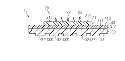
- the transdermal administration device 10 includes a microneedle 20 that is an example of an administration unit, and a support substrate 30 that is an example of a support that supports the microneedle 20.
- the microneedle 20 is provided with a base 21 having a flexible plate shape and a plurality of protrusions 22 protruding from the first surface 21S of the base 21.
- the base 21 has a first surface 21S that is a surface on which the protrusions 22 are arranged, and a second surface 21T that is a surface opposite to the first surface 21S, and the first surface 21S is the surface of the protrusions 22. Supports the proximal end.
- the outer shape of the base body 21 viewed from the direction facing the first surface 21S is not particularly limited, and the outer shape of the base body 21 may be rectangular, circular, or elliptical.
- the shape of the protrusion 22 may be a conical shape or a pyramid shape.
- the protruding portion 22 may have a shape with a sharp tip, such as a cylindrical shape or a prismatic shape.
- the protruding portion 22 may have a shape in which two or more solids are combined, such as a shape in which cones are stacked on a cylinder.
- the protrusion 22 may have any shape that can pierce the skin. Further, a constriction or a step may be formed on the side wall of the protrusion 22.
- the number of protrusions 22 is not particularly limited as long as it is 1 or more.
- each of the plurality of protrusions 22 may be arranged regularly or irregularly when viewed from the direction facing the first surface 21 ⁇ / b> S of the base 21. You may line up.
- the plurality of protrusions 22 are arranged in a lattice shape or a concentric shape.
- the support substrate 30 is located on the opposite side of the protrusion 22 with respect to the base 21 of the microneedle 20 and supports the base 21.
- the support substrate 30 has a plate shape with flexibility, and is a counter surface 31S that is an example of a support surface that supports the second surface 21T of the base body 21 and a side opposite to the counter surface 31S. It has an uneven surface 31T which is a surface.
- the opposing surface 31S is a flat surface, is directed to the second surface 21T of the base 21, has adhesiveness by application of an adhesive, and is bonded to the second surface 21T.
- the concavo-convex surface 31T includes the concavo-convex element 32 located on the belt, and one concavo-convex element 32 is either a convex portion protruding on the concavo-convex surface 31T or a concave portion recessed on the concavo-convex surface 31T.
- FIG. 1 shows an example in which the concavo-convex element 32 is a convex portion.
- the outer shape of the support substrate 30 as viewed from the direction facing the first surface 21S is not particularly limited, but the outer edge of the support substrate 30 preferably coincides with the outer edge of the base body 21 or is located outside the outer edge of the base body 21. .
- the entire base 21 preferably overlaps the support substrate 30 when viewed from the direction facing the first surface 21S.
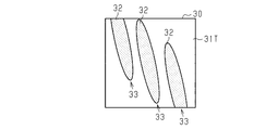
- FIG. 2 is a view of the transdermal administration device 10 as seen from the direction facing the uneven surface 31T of the support substrate 30, and is a view showing dots on the protrusions on the uneven surface 31T.
- the concavo-convex element 32 extends in a strip shape along the direction in which the facing surface 31 ⁇ / b> S spreads, and forms a strip pattern 33 that is a strip-like appearance shape.
- the uneven surface 31 ⁇ / b> T includes a plurality of uneven elements 32.
- Each concavo-convex element 32 is one convex portion, has a strip shape extending in one direction, and forms one strip pattern 33.
- the width of the concavo-convex element 32 in a direction orthogonal to the extending direction of the concavo-convex element 32 is constant. Then, as a result of each of the plurality of concavo-convex elements 32 forming a different strip pattern 33, the plurality of concavo-convex elements 32 form a plurality of strip patterns 33.
- the concavo-convex elements 32 adjacent to each other are arranged at intervals and extend along the same direction. That is, the plurality of belt-like patterns 33 extend linearly along the same direction and do not intersect each other.
- Each of the plurality of strip-shaped patterns 33 connects the end portions of the uneven surface 31T facing each other. In other words, each of the plurality of strip-shaped patterns 33 extends from one end side of the rectangular uneven surface 31T toward an end side facing this end side.
- the length Ht of the protrusion 22 is the maximum length of the protrusion 22 along the thickness direction of the base 21, that is, the direction orthogonal to the direction in which the first surface 21S of the base 21 spreads. In this case, the length is from the first surface 21S of the base 21 to the tip of the protrusion 22.
- the length Ht of the protrusion 22 is determined based on the depth of the hole that needs to be formed by the perforation of the protrusion 22 according to the purpose of the perforation by the protrusion 22 and the type of medicine to be administered.
- the length Ht of the protrusion 22 is preferably in the range of 20 ⁇ m to 1000 ⁇ m.
- the length of the protrusion 22 Ht is preferably not less than 200 ⁇ m and not more than 700 ⁇ m, and more preferably not less than 200 ⁇ m and not more than 600 ⁇ m.
- the drug can be delivered to a position deeper than the stratum corneum. Since the pores formed in the stratum corneum are closed over time, the stratum corneum serves as a barrier against the outside, so that the drug delivered below the stratum corneum is retained in the living body. Therefore, it is possible to reduce the exfoliation of the drug due to the metabolism of the stratum corneum and the washing of the skin for the purpose of skin care, etc., so that the state where the drug is held in the living body is maintained for a long period of time. .
- the length Ht of the protrusion 22 is preferably 30 ⁇ m or more and 300 ⁇ m or less, and more preferably 30 ⁇ m or more and 250 ⁇ m or less.
- the drug can stay in the stratum corneum. Since the stratum corneum is constantly generated by metabolism, the drug in the stratum corneum is discharged out of the body over time. For this reason, the state in which the medicine is held in the living body can be easily released by, for example, washing the skin or peeling the skin.
- the length Ht of each projection part 22 may mutually be the same, and may differ.
- the length Ht of the protrusions 22 arranged at the outer peripheral part among the plurality of protrusions 22 is larger than the length Ht of the protrusions 22 arranged at the center part, it is an administration target.
- the protrusions 22 are likely to come into contact with the skin along the curved surface.
- the width Dt of the protruding portion 22 is the maximum length of the protruding portion 22 in the direction parallel to the direction in which the first surface 21S of the base 21 spreads.
- the width Dt of the protrusion 22 is determined according to the required aspect ratio of the protrusion 22, the required volume of the hole, and the like.
- the width Dt of the protrusion 22 is preferably 1 ⁇ m or more and 300 ⁇ m or less.
- the diameter of a circle that is the bottom surface of the protrusion 22, that is, the bottom surface in contact with the first surface 21 ⁇ / b> S of the base 21 is the width Dt of the protrusion 22. .
- the length of the diagonal line in the square which is the bottom surface of the protrusion 22 in contact with the first surface 21S of the base 21 is the width Dt of the protrusion 22. It is.
- the tip angle ⁇ of the projection 22 is preferably 5 ° or more and 45 ° or less. More preferably, it is at least 25 ° and at most 25 °.
- the tip angle ⁇ of the protrusion 22 is the maximum value of the angle formed by the tip of the protrusion 22 in the cross section in the thickness direction of the base 21.
- the tip angle ⁇ of the protrusion 22 is the apex angle of a triangle having the square diagonal line of the bottom of the protrusion 22 as the base and the apex of the regular pyramid as the apex.
- the shape of the protrusion 22 is not limited to the shape exemplified in the above description, and may be determined as appropriate according to the purpose of perforation by the protrusion 22 and the type of drug to be administered.
- the purpose of the perforation by the protrusion 22 includes the purpose of promoting percutaneous absorption of the drug and the purpose of taking out the substance in the living body through the skin.
- the shape of the protrusion 22 may be determined from the viewpoint of improving the performance of perforating the skin.
- the plurality of protrusions 22 may include protrusions 22 having different shapes.
- the thickness Tk of the base body 21 is the length of the base body 21 along the thickness direction of the base body 21, and is the length from the first surface 21S to the second surface 21T.
- the thickness Tk of the base 21 is not particularly limited, but is preferably 10 ⁇ m or more and 2 mm or less.
- the microneedle 20 is used to administer a drug from the skin, it is preferable to use a biocompatible material as a material for forming the microneedle 20 as described later.
- a material having biocompatibility is expensive compared to a general material having no biocompatibility. Therefore, from the viewpoint of reducing the manufacturing cost, it is preferable that the amount of the material used for forming the microneedle 20 is as small as possible.
- One of the measures for reducing the amount of the material used to form the microneedles 20 is to reduce the thickness Tk of the base body 21, but the rigidity of the base body 21 decreases as the thickness Tk of the base body 21 decreases.
- the variation in the shape of the base body 21 when an external force is applied to the base body 21 becomes large.
- this tendency is remarkable when the rigidity of the base body 21 is so low that the base body 21 is easily deformed into an unexpected shape when the thickness Tk of the base body 21 is within the above range. Therefore, the smaller the thickness Tk of the base body 21 is, the higher the effect of the effect of the transdermal administration device 10 of this embodiment, that is, the effect of suppressing the variation in the shape of the base body 21 when an external force is applied to the base body 21.
- the thickness Tk of the substrate 21 is 10 ⁇ m or more and 500 ⁇ m or less, a higher effect can be obtained by the transdermal administration device 10 of the present embodiment.
- the base 21 when the base 21 is low in rigidity and easily deformed into an unexpected shape, the base 21 has a lower rigidity as the size of the base 21 spreading, that is, the area of the first surface 21S increases. Is more likely to deform due to unexpected shapes. Therefore, the larger the area of the first surface 21S, the higher the beneficial effect of the effect of the transdermal administration device 10 of the present embodiment, that is, the effect of suppressing variation in the shape of the base 21 when an external force is applied to the base 21. . From such a viewpoint, in order to obtain a higher effect by the transdermal administration device 10 of the present embodiment, the area of the first surface 21S of the base 21 is preferably 0.2 cm 2 or more, and more preferably 1 cm 2 or more. Preferably, it is preferably 3 cm 2 or more.
- the rigidity of the base body 21 is high and the base body 21 is difficult to bend, it is difficult to apply a force to the base body 21 so as to bend in a specific direction as the area of the first surface 21S increases. Also in this case, the variation in the shape of the base 21 when an external force is applied to the base 21 becomes large. Therefore, even when the base 21 that is highly rigid and difficult to bend is used, the greater the area of the first surface 21S, the higher the effect obtained by the transdermal administration device 10 of the present embodiment.
- the area of the first surface 21S is the entire area of the first surface 21S including the region where the protrusions 22 are arranged in the first surface 21S.
- the convex portion on the uneven surface 31T of the support substrate 30 has a large thickness in the support substrate 30 and thereby is located on the surface of the high-rigidity portion 34 that is a portion having high bending rigidity.
- the concave portion on the uneven surface 31T has a thickness smaller than that of the high-rigidity portion 34 in the support substrate 30, and is thereby positioned on the surface of the low-rigidity portion 35 having low bending rigidity.
- the maximum thickness TsM of the support substrate 30 is the maximum value of the length of the support substrate 30 along the thickness direction of the base 21. That is, the maximum thickness TsM of the support substrate 30 is the length from the facing surface 31S in the thickness direction of the base body 21 to the most protruding portion of the concavo-convex surface 31T.
- the minimum thickness Tsm of the support substrate 30 is the minimum value of the length of the support substrate 30 along the thickness direction of the base 21. That is, the minimum thickness Tsm of the support substrate 30 is the length from the facing surface 31S in the thickness direction of the base 21 to the most recessed portion in the concavo-convex surface 31T.
- the maximum thickness TsM of the support substrate 30 is preferably a size having such a rigidity that the support substrate 30 is not deformed by its own weight when the thickness of the support substrate 30 is constant at the maximum thickness TsM. It is determined according to the size and material of the support substrate 30. When the support substrate 30 is made of resin, the maximum thickness TsM is set, for example, within a range of 50 ⁇ m to 5 mm.
- the minimum thickness Tsm of the support substrate 30 is such that the support substrate 30 can be bent by applying an external force to the support substrate 30 when the thickness of the support substrate 30 is constant at the minimum thickness Tsm. It is sufficient that the support substrate 30 has such a rigidity.
- the uneven depth Ta is the size of the step of the uneven surface 31T in the thickness direction of the base body 21, and is the length from the top of the convex portion and the bottom of the concave portion adjacent to each other.
- the unevenness depth Ta is set, for example, within a range of 1/20 or more and 19/20 or less of the maximum thickness TsM so that the minimum thickness Tsm becomes a value within a desired range.
- the maximum thickness TsM of the support substrate 30 is preferably larger than the thickness Tk of the base 21 from the viewpoint of easily deforming the base 21 by following the deformation of the support substrate 30.
- the uneven depth Ta is preferably larger than the length Ht of the protrusion 22 from the viewpoint of easily guiding the shape of the support substrate 30 by the uneven element 32.
- FIGS. 4 to 9 are views of the transdermal administration device 10 as seen from the direction facing the uneven surface 31T of the support substrate 30, and are drawings showing dots on the protrusions on the uneven surface 31T.
- the plurality of strip patterns 33 may include strip patterns 33 extending in different directions.
- each concavo-convex element 32 is one convex portion, has a strip shape extending along one direction, and forms one strip pattern 33.
- the plurality of concavo-convex elements 32 include concavo-convex elements 32 extending in different directions.
- the concavo-convex elements 32 have different directions.
- a plurality of strip-shaped patterns 33 including a strip-shaped pattern 33 extending linearly along the line are formed.
- Each of the plurality of strip-like patterns 33 connects the end portions of the uneven surface 31T facing each other.
- the band-shaped patterns 33 adjacent to each other do not intersect or one of the two ends of the band-shaped pattern 33 is connected to each other.
- the band-shaped patterns 33 adjacent to each other do not intersect.
- a configuration may be adopted in which some of the strip-shaped patterns 33 in the plurality of strip-shaped patterns 33 are connected to one of the two end portions of the strip-shaped pattern 33 and the other strip-shaped patterns 33 do not intersect each other.
- the plurality of concavo-convex elements 32 may include concavo-convex elements 32 having different shapes as viewed from the direction facing the concavo-convex surface 31T.
- the plurality of concavo-convex elements 32 have concavo-convex shapes in which the width in the direction orthogonal to the extending direction of the concavo-convex elements 32 decreases toward one of the two ends of the concavo-convex elements 32. Element 32 is included.
- the belt-like pattern 33 may extend in a curved shape.
- each concavo-convex element 32 is one convex part, has a belt-like shape extending while being bent, and forms one belt-like pattern 33.
- the plurality of concavo-convex elements 32 have the same bent band shape, and each concavo-convex element 32 forms a different strip-shaped pattern 33, and as a result, the plurality of concavo-convex elements 32 form a plurality of strip-shaped patterns 33 extending in a curved shape. Has been.
- the plurality of concavo-convex elements 32 having the same bent band shape are arranged in the same direction, and in such a configuration, the plurality of band-shaped patterns 33 extend in the same direction.
- Each of the plurality of strip-like patterns 33 connects the end portions of the uneven surface 31T facing each other.
- the plurality of strip-shaped patterns 33 extending in a curved shape may include strip-shaped patterns 33 extending in different directions.
- each concavo-convex element 32 is one convex part, has a belt-like shape extending while being bent, and forms one belt-like pattern 33.
- the plurality of concavo-convex elements 32 include concavo-convex elements 32 having different bent band shapes, and each concavo-convex element 32 forms a different strip-shaped pattern 33.
- different concavo-convex elements 32 have different curves.
- a plurality of strip-shaped patterns 33 including a strip-shaped pattern 33 extending in a shape are formed.
- the plurality of strip-shaped patterns 33 include strip-shaped patterns 33 extending in different directions.
- Each of the plurality of strip-like patterns 33 connects the end portions of the uneven surface 31T facing each other.
- belt-shaped pattern 33 extended in a mutually different direction may be formed by arrange
- the band-shaped patterns 33 adjacent to each other do not intersect or one of the two ends of the band-shaped pattern 33 is connected to each other.
- the band-shaped patterns 33 adjacent to each other are connected to one of the two end portions of the band-shaped pattern 33.
- a configuration may be adopted in which some of the strip-shaped patterns 33 in the plurality of strip-shaped patterns 33 are connected to one of the two end portions of the strip-shaped pattern 33 and the other strip-shaped patterns 33 do not intersect each other.
- a concave portion is formed between the convex portions which are the concave and convex elements 32 adjacent to each other, and some of the plurality of concave portions also extend in a strip shape on the concave and convex surface 31T.
- the belt-like pattern 33 only needs to have a shape extending from one end side to the other end side of the concavo-convex surface 31T.
- FIGS. May be regarded as the concavo-convex element 32 that forms the belt-like pattern 33.
- the convex portion has a band shape sandwiched between two concave portions, and The concave portion has a belt shape sandwiched between two convex portions, and at least one of them is satisfied.
- belt shape which is at least one of a convex part and a recessed part is the uneven
- the strip-shaped pattern 33 is anisotropic, that is, spreads in a biased direction on the uneven surface 31T.
- the position of the concave portion is changed to a convex portion in the concave and convex surface 31T, and the position of the convex portion is changed to a concave portion in the concave and convex surface 31T.
- the unevenness on the uneven surface 31T may be reversed.
- each concavo-convex element 32 is one convex portion, or an elliptical shape extending along one direction when viewed from the direction facing the concave-convex surface 31T, or one of such elliptical shapes.
- One band-like pattern 33 is formed having a shape that is a portion. At least one of the two end portions in the extending direction of the uneven element 32 does not reach the end portion of the uneven surface 31T.
- one belt-like pattern 33 is composed of one structure extending in a belt shape that is a convex portion or a concave portion, but one belt-like pattern 33 is a plurality of dots scattered on a virtual belt. You may comprise from the structure of.
- each belt-like pattern 33 is composed of a concavo-convex element 32 that is a plurality of structures.
- Each concavo-convex element 32 is one convex portion having a rectangular shape when viewed from the direction facing the concavo-convex surface 31T.
- the plurality of strip-shaped patterns 33 extend linearly along the same direction and do not intersect each other.
- the shape of the concavo-convex element 32 constituting each strip pattern 33 is not limited to a rectangular shape, and the concavo-convex element 32 has, for example, a circular shape when viewed from the direction facing the concavo-convex surface 31T. May be.
- the uneven surface 31T may include a strip pattern 33 that isotropically expands in all directions along the facing surface 31S in addition to the strip pattern 33 that extends anisotropically.
- the uneven surface 31T includes a belt-like pattern 33a and a belt-like pattern 33b.
- the belt-like pattern 33a extends in a curved shape so as to connect opposite ends of the uneven surface 31T, that is, spreads anisotropically on the uneven surface 31T.
- the belt-like pattern 33b has an annular shape centered on the center of the uneven surface 31T, that is, isotropically spreads on the uneven surface 31T. In other words, it is only necessary that one pattern formed by all the strip-like patterns 33 included in the uneven surface 31T spreads anisotropically when viewed from the direction facing the uneven surface 31T.
- the belt-like pattern 33 may have a configuration in which the configurations shown in FIGS. 2 and 4 to 9 are combined.
- each strip pattern 33 shown in FIGS. 4 to 7 may be formed of a plurality of concave and convex elements 32 as in the configuration shown in FIG.
- the plurality of strip-shaped patterns 33 may include a strip-shaped pattern 33 that extends in a curved line and a strip-shaped pattern 33 that extends in a straight line.
- the outer peripheral surface of the concavo-convex element 32 which is a convex portion may be a flat surface as shown in FIGS. 1 and 3, or may be a curved surface as shown in FIG. Moreover, a flat surface and a curved surface may be included in the outer peripheral surface of the concavo-convex element 32 which is a convex portion.
- the concavo-convex element 32 that is a convex portion may have a rectangular parallelepiped shape, a dome shape, a pyramid shape, or a conical shape.
- the inner peripheral surface of the concave / convex element 32 that is a concave portion may be a flat surface, a curved surface, or the inner peripheral surface of the concave / convex element 32 may include a flat surface and a curved surface.
- the number of the band-shaped patterns 33 may be one or more.
- the arrangement of the band-like patterns 33 when the number of 33 is plural may be determined according to the ease of bending required for the support substrate 30, the direction required to be easily bent, and the like.
- the microneedle 20 is preferably formed from a material having biocompatibility.
- the material having biocompatibility is a material having a small influence on a living body, and includes a water-soluble polymer, a water-insoluble polymer, a biopolymer, a resin, a polysaccharide, and the like.
- biocompatible materials include carboxymethylcellulose, methylcellulose, hydroxypropylcellulose, hydroxypropylmethylcellulose, alginate, curdlan, chitin, chitosan, glucomannan, polymalic acid, collagen, collagen peptide, gelatin, silicon , Titanium, silicone, polylactic acid, polyglycolic acid and the like, but are not limited to these materials.
- polysaccharide trehalose or maltose can be used.
- carboxymethylcellulose, hydroxypropylcellulose, and hydroxypropylmethylcellulose can be suitably used because they are biologically safe.
- Chitin, chitosan, and chitosan derivatives with biocompatibility may use crustacean-derived materials such as shrimp and shrimp, plant-derived materials that are produced by mycelium and microorganisms, and materials that use these as starting materials. it can.
- Chitosan, chitin / chitosan, and chitin / chitosan derivatives are preferable as a material for forming the microneedle 20 because they have a cosmetic effect on the skin and have a bactericidal and antibacterial effect.
- the method of administration of the drug using the microneedle 20 is not particularly limited.
- the drug when the drug is applied to the surface of the protrusion 22 and the protrusion 22 pierces the skin, the drug is sent into the skin. May be.
- the protrusion 22 may contain a medicine, and the protrusion 22 may be dissolved while the protrusion 22 is stuck in the skin, so that the medicine may be sent into the skin.
- a liquid medicine may be applied to the skin, and the medicine may be fed into the skin from the hole formed by the protrusion 22.
- the drug may be administered in a form in which these methods are combined.
- the protrusion 22 may be removed from the skin after being stabbed into the skin, or may be buried in the skin.
- the drug is not particularly limited as long as it is a substance that functions by being administered intradermally.
- examples of the drug include physiologically active substances and cosmetic compositions having a cosmetic effect.
- an odor is generated when the transdermal administration device 10 is used. Therefore, the transdermal administration device 10 suitable for use as a cosmetic product can be realized.
- the drug may include a biologic. Biologics are drugs that use raw materials or materials derived from human or animal cells, cell tissues, and the like.
- the drug may be applied to the surface of the protrusion 22, included in the protrusion 22, or applied to the skin, depending on the method of administration of the drug.
- Drugs may be utilized in a combined manner.
- the base body 21 and the protrusions 22 may be formed of materials having the same composition, or may be formed of materials having different compositions. In the configuration in which the base 21 and the protrusion 22 are formed of materials having the same composition, the base 21 and the protrusion 22 can be easily formed by integral formation.
- the microneedle 20 can be manufactured using various known techniques. For example, when resin is used as the material of the microneedle 20, the microneedle 20 can be formed by a molding technique such as injection molding, extrusion molding, imprinting, hot embossing, or casting. Further, the microneedle 20 can be formed by using a machining method such as a cutting method or an etching method. In addition, an original plate of the microneedle 20 is manufactured by such a method, an intaglio plate in which the unevenness of the original plate is inverted by a plating method or a mold making method using a resin, and the microneedle 20 is manufactured using the manufactured intaglio plate. You may duplicate.
- the support substrate 30 can maintain its own shape by its own weight, and imparts rigidity to the support substrate 30 by bending the support substrate 30 by applying an external force to the support substrate 30 by a human hand. It is preferably formed from possible materials. As a specific material of the support substrate 30, a synthetic resin, paper, wood, metal, or the like may be used.
- action which the transdermal administration device 10 of this embodiment brings is demonstrated.
- the support substrate 30 has the low-rigidity portion 35 and the high-rigidity portion 34, when the support substrate 30 is bent by application of external force, the bent portion of the support substrate 30 is easily formed in the low-rigidity portion 35. It is difficult to form the rigid portion 34.
- the low rigidity portion 35 extends along the belt-like pattern 33. That is, when the belt-like pattern 33 is formed of a convex portion, the low-rigidity portion 35 is located around the belt-like pattern 33, and when the belt-like pattern 33 is formed of a concave portion, the low-rigidity portion 35 is positioned of the belt-like pattern 33.
- the support substrate 30 is easily bent so as to bend along the direction in which the belt-like pattern 33 extends in a direction orthogonal to the direction in which the belt-like pattern 33 extends. Further, for example, when the extending direction of the belt-like pattern 33 changes in the middle of the belt-like pattern 33 as in the case where the belt-like pattern 33 extends in a curved line, the direction in which the support substrate 30 is easily bent also changes according to the change. To do.
- the support substrate 30 is easily bent in a specific direction defined by the belt-like pattern 33, the base 21 is curved by bending the base 21 of the microneedle 20 supported by the support substrate 30 together with the support substrate 30. Can be curved in a specific direction. That is, even if the direction of the external force acting on the base 21 is different every time the external force is applied, the support substrate 30 is easy to bend with the base 21 using the low-rigidity portion 35 as a bending portion, and is difficult to bend at the high-rigidity portion 34.
- the shape of the base body 21 when an external force is applied to the base body 21 is either a shape that does not bend substantially at the portion where the belt-like pattern 33 is located, or a shape that is largely bent at the portion where the belt-like pattern 33 is located. Guided by the pattern 33.
- the shape of the support substrate 30 to which an external force is applied is the portion where the band-shaped pattern 33 is positioned.
- the portion of the support substrate 30 having a large curvature radius is guided along the direction in which the belt-like pattern 33 extends. Therefore, it is possible to suppress variations in the shape of the base 21.
- the support substrate is easily curved in a specific direction.
- the deformation of the base body 21 can be easily controlled, and the base body 21 follows the support substrate 30 and bends in a specific direction. As a result, variations in the shape of the substrate 21 can be suppressed.
- the base body 21 when the base body 21 is made of chitosan and the base body 21 has high rigidity and is difficult to bend, force is applied to the base body 21 through the support substrate 30 that is easily bent in a specific direction.
- a force for bending the base body 21 in the specific direction is concentrated on the base body 21.
- the base 21 is curved in a specific direction following the support substrate 30, and variations in the shape of the base 21 are suppressed.
- the base 21 of the microneedle 20 can be easily bent in a specific direction defined by the strip pattern 33. Then, the substrate 21 is easily bent along the skin of the administration target by applying the transdermal administration device 10 to the administration target in accordance with the direction corresponding to the direction of bending of the skin that is the administration target. Can be made.
- the support substrate 30 having the belt-like pattern 33 is bent at a portion having low rigidity.
- the shape of is difficult to return from the curved state. Therefore, it is easy to maintain the base 21 along with the support substrate 30 in a curved state along the skin to be administered.
- the user In using the transdermal administration device 10, the user usually holds the transdermal administration device 10 so as to support the uneven surface 31T. At this time, since the uneven surface 31T has unevenness, it is difficult to slip. Therefore, since the user can easily support the uneven surface 31T, the transdermal administration device 10 is easy to handle. As a result, it is possible to prevent the perforating function of the protrusion 22 from being deteriorated due to the deformation of the shape of the protrusion 22 by the user touching the protrusion 22 unintentionally.
- the transdermal administration device 11 of the first modified example includes an adhesive sheet 40 in addition to the microneedles 20 and the support substrate 30.
- the pressure-sensitive adhesive sheet 40 has a pressure-sensitive adhesive surface 41 ⁇ / b> S and a fixed surface 41 ⁇ / b> T opposite to the pressure-sensitive adhesive surface 41 ⁇ / b> S, and the outer surface of the base 21 of the microneedle 20 on the facing surface 31 ⁇ / b> S of the support substrate 30. Is arranged.
- the support substrate 30 when viewed from the direction facing the first surface 21 ⁇ / b> S of the base body 21, the support substrate 30 protrudes outside the base body 21, and the fixing surface 41 ⁇ / b> T of the adhesive sheet 40 is formed on the surface 21 ⁇ / b> S of the support substrate 30. It is fixed to the part that protrudes to the outside.
- the adhesive surface 41 ⁇ / b> S is located outside the substrate 21 when viewed from the direction facing the first surface 21 ⁇ / b> S of the substrate 21. That is, the support substrate 30 supports the base 21 and the adhesive sheet 40.
- the outer edge of the pressure-sensitive adhesive sheet 40 may be located on the outer side of the outer edge of the support substrate 30 or on the inner side when viewed from the direction facing the first surface 21 ⁇ / b> S of the base body 21.
- the outer shape is not limited. However, a configuration in which the outer edge of the adhesive sheet 40 matches the outer edge of the support substrate 30 when viewed from the direction facing the first surface 21S of the base body 21 is preferable because the transdermal administration device 11 is easy to handle. In addition, a configuration in which the thickness of the pressure-sensitive adhesive sheet 40 is approximately equal to or less than the thickness Tk of the base body 21 is preferable because the protrusion 22 is easily stuck in the administration target up to its base end.
- the pressure-sensitive adhesive sheet 40 has, for example, a structure in which pressure-sensitive adhesive layers are laminated on both surfaces of a resin sheet, and at least the material of the pressure-sensitive adhesive layer constituting the pressure-sensitive adhesive surface 41S is preferably a biocompatible material. Moreover, the adhesive surface 41S which is the surface of one adhesive layer can hold the microneedle 20 and can maintain the state in which the adhesive sheet 40 is adhered to the administration target over a desired period. It is preferable to have.
- the base 21 is curved together with the support substrate 30, the base 21 is pressed against the skin to be administered, and the adhesive surface 41S of the adhesive sheet 40 is attached to the skin to be administered. It is done. Thereby, the curved base 21 is disposed along the skin of the administration target, and the microneedle 20 is fixed to the administration target in a state where the protrusion 22 is stuck in the skin.
- the base 21 in the transdermal administration device 11 including the adhesive sheet 40, the base 21 can be easily bent along the skin to be administered, and the base 21 is disposed along the skin, that is, the percutaneous.
- the transdermal administration device 11 can be fixed to the administration subject in a state where the shape of the administration device 11 is an optimal shape for administration of the drug. Therefore, it becomes easy to administer the drug accurately.
- the thickness of the portion supporting the base 21 is larger than the thickness of the portion supporting the adhesive sheet 40. large.
- the first surface 21 ⁇ / b> S of the base 21 protrudes more than the adhesive surface 41 ⁇ / b> S of the adhesive sheet 40.
- the facing surface 31S is a surface having a step.
- the support substrate 30 may be formed by subjecting one sheet to a process of partially changing the thickness, and a plurality of sheets are laminated on the thick portion of the support substrate 30. May be formed.
- the protrusion 22 located on the first surface 21S of the base body 21 protrudes from the proximal end to the proximal end than the other members of the transdermal administration device 12, the protrusion 22 is It becomes easy to pierce the skin to be administered to the end.
- a third modification of the transdermal administration device of the above embodiment will be described.
- the third modification differs from the first modification in the arrangement of the pressure-sensitive adhesive sheet 40 and in the configuration of the support.
- the adhesive sheet 40 is located between the microneedle 20 and the support substrate 30, and the support substrate 30 supports the adhesive sheet 40. .
- the fixing surface 41T of the adhesive sheet 40 is fixed to the opposing surface 31S of the support substrate 30, and the second surface 21T of the base body 21 is attached to the adhesive surface 41S.
- the adhesive sheet 40 protrudes outside the base body 21, and the adhesive surface 41S is exposed.
- the adhesive sheet 40 is also disposed in a region overlapping the base body 21 when viewed from the direction facing the first surface 21S of the base body 21.
- the support is composed of the support substrate 30 and the adhesive sheet 40, and the adhesive surface 41S constitutes the support surface of the support.
- the pressure-sensitive adhesive sheet 40 has a simple shape as compared with the case where the pressure-sensitive adhesive sheet 40 is formed in an annular shape surrounding the base body 21 as in the first and second modified examples.
- the sheet 40 can be easily manufactured, and the positioning of the microneedles 20, the support substrate 30, and the adhesive sheet 40 can be easily performed.
- the adhesive surface 41S may not be disposed so as to surround the entire outer peripheral edge of the substrate 21 when viewed from the direction facing the first surface 21S of the substrate 21.
- the adhesive surface 41 ⁇ / b> S may protrude from only a part of the outer peripheral edge of the base 21.
- the transdermal administration device 14 of the fourth modified example has a protective sheet 50 in addition to the microneedles 20, the support substrate 30, and the adhesive sheet 40.
- the protective sheet 50 covers the pressure-sensitive adhesive surface 41 ⁇ / b> S of the pressure-sensitive adhesive sheet 40 exposed to the outside of the substrate 21 when viewed from the direction facing the first surface 21 ⁇ / b> S of the substrate 21.
- the protective sheet 50 is affixed to the pressure-sensitive adhesive surface 41S so that it can be peeled off from the pressure-sensitive adhesive sheet 40 by a force that is generated when a user pinches and pulls the protective sheet 50 with a finger.
- the forming material of the protective sheet 50 has an adhesive force that allows the adhesive surface 41S to hold the state where the adhesive sheet 40 is adhered to the administration target for a desired period after the protective sheet 50 is peeled from the adhesive sheet 40.
- the non-biocompatible material does not remain on the adhesive surface 41S.
- the base 21 is curved together with the support substrate 30 in the same manner as in the first modified example, and the base 21 is to be administered.
- the pressure-sensitive adhesive surface 41S of the pressure-sensitive adhesive sheet 40 is affixed to the skin to be administered.
- the adhesive surface 41S of the adhesive sheet 40 can be protected until it is affixed to the administration target.
- the edge part of the protection sheet 50 protrudes rather than the front-end
- the protrusion 22 can be protected by the protective sheet 50.
- FIG. 14 an example in which the protective sheet 50 is provided in the configuration of the third modified example is illustrated, but the protective sheet 50 may be provided in the configuration of the first modified example and the second modified example.
- [Fifth Modification] A fifth modification of the transdermal administration device of the above embodiment will be described.
- the transdermal administration device 15 of the fifth modified example includes a container 60 that accommodates the microneedle 20 and the support substrate 30 in addition to the microneedle 20 and the support substrate 30.
- the container 60 is made of resin, for example, and has a box shape or a bag shape.
- the container 60 is configured such that the microneedles 20 and the support substrate 30 can be taken out by partly cutting the container 60 or disassembling the container 60.
- the protrusion 22 of the microneedle 20 is protected by the container 60.
- the container 60 may not cover the entire microneedles 20 and the support substrate 30.
- the container 60 may have a lid-like shape that covers only the microneedles 20.
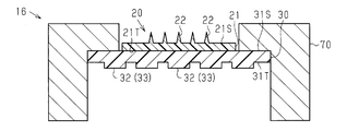
- the transdermal administration device 16 of the sixth modification includes an applicator 70 having a function of assisting perforation of the skin by the protrusion 22 in addition to the microneedle 20 and the support substrate 30.
- the applicator 70 may have a portion that functions as a handle when the user pierces the skin to be administered with the protrusion 22, or applies a force to the support substrate 30 to connect the support substrate 30 and the base body 21.
- a mechanism for bending may be provided, or a mechanism for applying an urging force for piercing the skin to the protrusion 22 may be provided.
- the applicator 70 supports, for example, the outer peripheral portion of the support substrate 30, and the protrusion 22 is exposed to the outside of the applicator 70 from the end of the applicator 70.
- the transdermal administration device 17 of the seventh modified example is used together with an apparatus including an installation unit 80 on which the support substrate 30 is installed.
- This apparatus may be, for example, an apparatus for storing the transdermal administration device 17, or may be an apparatus that performs a predetermined process on the microneedles 20 before and after skin perforation by the protrusions 22.
- the device may have a function as a sensor that acquires information using skin perforation by the protrusion 22.
- the installation unit 80 has irregularities obtained by reversing the irregularities of the irregular surface 31T of the support substrate 30, and the irregularities of the irregular surface 31T are fitted into the irregularities of the installation unit 80, whereby the transdermal administration device 17 is attached to the installation unit 80. Installed.
- the transdermal administration device 17 may be installed in the installation unit 80 in a state where the base 21 is curved together with the support substrate 30.
- the support substrate 30 and the base 21 may be curved together with the installation portion 80, or the support substrate 30 and the base 21 may be separated from the installation portion 80. May be curved.
- the transdermal administration devices of the fifth to seventh modifications may include the adhesive sheet 40 and the protective sheet 50 as in the configurations exemplified as the first to fourth modifications.
- the high rigidity portion is a portion having high rigidity in the support
- the low rigidity portion is a portion having low rigidity in the support
- the support has at least one of the high rigidity portion and the low rigidity portion.
- Any configuration that extends in a strip shape or is disposed in a strip shape may be used.
- the thick portion of the support is a high-rigidity portion.
- the thin part is the low rigidity part.
- the thickness of the support is the thickness of the space occupied by the material forming the support.
- the portion where the occupancy of the vacancies in the support is low is the high-rigidity portion
- the void in the support is A portion with a high hole occupation ratio is a low-rigidity portion.
- the portion formed from the first material has high rigidity.
- the portion formed from the second material is a low-rigidity portion.
- a support is configured as a laminated body of a first support substrate formed from the first material and a second support substrate formed from the second material, and the second support substrate is formed on the opposing surface 31S described above. While spreading throughout, the 1st support substrate formed in strip shape may be laminated on a part of the 2nd support substrate.
- the shape of the protrusion 22 included in the administration unit is not limited to the needle shape, that is, the shape extending along the direction orthogonal to the first surface 21S of the base body 21.
- the shape of the protruding portion 22 is a blade shape, that is, the protruding portion 22 extends along one extending direction that is the direction along the first surface 21S of the base body 21, and the tip of the protruding portion 22 is the first end of the base body 21.
- the shape formed in the linear form extended in the direction different from the direction orthogonal to the 1st surface 21S, for example, the direction along the extending direction may be sufficient.
- the protrusion 22 has a triangular prism shape extending along the extending direction, and one of three rectangular side surfaces of the triangular prism is in contact with the base body 21 and the side that divides the other two side surfaces is formed. You may have the shape which functions as a front-end
- FIG. 1 A perspective view of the projection part 22.
- the effects listed below can be obtained.
- the support substrate 30 When an external force is applied to the support substrate 30, the support substrate 30 is easy to bend together with the base body 21 with the low-rigidity portion 35 as a bending portion, and the high-rigidity portion 34 is not easily bent.
- the shape of the base body 21 when an external force is applied to the base body 21 is either a shape that does not substantially bend at a position where the belt-like pattern 33 is located, or a shape that is largely bent at a place where the belt-like pattern 33 is located. Therefore, variation in the shape of the base body 21 can be suppressed.
- the low-rigidity portion 35 includes a concave portion
- the high-rigidity portion 34 includes a convex portion
- the low-rigidity portion 35 and the high-rigidity portion 34 are determined by the thickness of the support substrate 30. That is, since the distribution of rigidity of the support substrate 30 can be determined by the step included in the uneven surface 31T, it is easy to partition the high rigidity portion 34 and the low rigidity portion 35 in the support.
- the belt-like pattern 33 is constituted by the concavo-convex element 32 that is one structure having a belt-like shape, it is possible to improve the reproducibility of the shape of the base 21 guided by the belt-like pattern 33. Further, in the configuration including the concavo-convex elements 32 which are a plurality of structures interspersed with the band-shaped pattern 33, it is easy to make the shape of the base body 21 guided by the band-shaped pattern 33 complicated.
- the shape of the support substrate 30 is easily guided by the band-shaped pattern 33 as compared with the configuration in which the number of the band-shaped patterns 33 is one.
- the site to which the transdermal administration device is applied in the skin to be administered usually has a rare complex shape with repeated large irregularities.
- the plurality of strip-shaped patterns 33 do not intersect with each other or a configuration in which the plurality of strip-shaped patterns 33 are connected at one end of the strip-shaped pattern 33, it is possible to suppress the branching direction of the support substrate 30 from being complicated. Therefore, it is suitable for applications in which the base 21 is bent greatly, and it is easy to make the shape and position of the base 21 follow the skin shape.
- the plurality of strip-shaped patterns 33 include the strip-shaped patterns 33 that extend linearly, it is possible to simplify the shape guided by the strip-shaped patterns 33, and the strip-shaped patterns 33 that extend linearly. With respect to the above, it is easy to design the arrangement of the belt-like pattern 33.
- the curved surface of the skin to be administered to which the transdermal administration device is applied does not have a complicated shape within one administration site, the size of the curved surface and the curvature of the curved surface are slightly different for each administration site.
- the plurality of strip patterns 33 include the strip patterns 33 extending in different directions or the strip patterns 33 extending in a curved shape, the degree of curvature of the support substrate 30 can be changed in the support substrate 30. Therefore, by setting the arrangement and shape of the belt-like pattern 33 according to the degree of curvature of the administration site, it becomes easier to curve the base body 21 along the skin of the administration target.
- the adhesive surface 41S adheres to the skin to be administered, so that the substrate 21 can be easily bent along the skin to be administered.
- the transdermal administration device can be fixed to the administration target in a state where the base 21 is disposed along the skin of the administration target, it is possible to ensure a sufficient time for the protrusion 22 to pierce the administration target. But there is.
- Example 1 The transdermal administration device described above will be described using specific examples and comparative examples.
- Example 1> (Production of transdermal administration device) Step 1. Production of Intaglio First, a microneedle master was produced by precision machining. Using a silicon substrate as a material for forming the original plate, an original plate is produced in which 60 projections of regular square pyramids (height: 120 ⁇ m, bottom surface: 38 ⁇ m ⁇ 38 ⁇ m) are arranged in a grid of 6 columns and 10 rows at intervals of 3 mm. did. The 60 protrusions were arranged in a rectangular area of about 30 mm ⁇ about 20 mm.
- Step 2 Preparation of Microneedle Material Solution
- a microneedle material solution was prepared. Hydroxypropyl cellulose was dissolved in water using an acid and then deaerated under vacuum to prepare a material solution for microneedles. At this time, the proportion of hydroxypropylcellulose in the material solution was 5% by weight.
- Step 3 the microneedle material solution prepared in Step 2 was supplied into the intaglio plate produced in Step 1 by an inkjet method, and the material solution was filled in the recesses. After drying the material solution in the recess, the molded product was peeled from the intaglio plate to obtain a microneedle.
- the thickness of the base of the obtained microneedle was 200 ⁇ m, and the length of the protrusion was 120 ⁇ m.
- substrate was shape
- Step 4 Preparation of transdermal administration device
- the microneedles formed in step 3 were combined with a support substrate and an adhesive sheet to prepare a transdermal administration device.
- the support substrate is made of polyethylene, and the outer shape of the support substrate is a rectangle of about 40 mm ⁇ about 30 mm.
- a plurality of convex portions extending linearly in the same direction are formed at equal intervals as the concavo-convex element.
- the width of the concavo-convex element in the direction orthogonal to the direction in which the concavo-convex element extends is 0.5 mm, and the interval between the concavo-convex elements adjacent to each other is 0.5 mm.
- the maximum thickness TsM of the support substrate is 1 mm, the minimum thickness Tsm is 0.5 mm, and the unevenness depth Ta is 0.5 mm.
- the pressure-sensitive adhesive sheet is a pressure-sensitive adhesive sheet for skin application having both sides of adhesiveness, and the outer shape of the pressure-sensitive adhesive sheet is a rectangle of about 40 mm ⁇ about 30 mm.
- the thickness of the pressure-sensitive adhesive sheet is 500 ⁇ m.
- the opposing surface which is the surface opposite to the concavo-convex surface on which the concavo-convex element of the support substrate was formed, was bonded to the fixed surface, which is one surface of the adhesive sheet. Furthermore, the 2nd surface of the base
- the transdermal administration device of Example 1 was obtained.
- a microneedle is disposed at the center of a rectangular adhesive sheet of about 40 mm ⁇ about 30 mm, and an adhesive surface having a width of 5 mm is exposed so as to surround the outer periphery of the substrate.
- an uneven surface having a belt-like pattern is located on the side opposite to the protrusion with respect to the base.
- the transdermal administration device of Example 1 was placed on the curved portion of the left upper arm so that the direction in which the band-shaped pattern extends, that is, the direction in which the concavo-convex element extends was orthogonal to the direction in which the skin bends. Then, a force was applied to the support substrate with a finger to press the transdermal administration device against the skin. As a result, the substrate was easily bent along the skin. Since the base made of hydroxypropylcellulose has low rigidity and it is difficult to control the deformation, it is difficult to bend only the base into the same shape every time, but it follows the support substrate by bending the base together with the support substrate. Thus, the substrate can be easily bent, and reproducibility of the bent shape was recognized. In addition, the transdermal administration device was fixed to the skin with the substrate along the skin by the adhesive sheet sticking to the skin.
- the support substrate is made of polyethylene, and the outer shape of the support substrate is a rectangle of about 40 mm ⁇ about 30 mm.
- the support substrate has a flat plate shape, does not have an uneven element, and the thickness of the support substrate is constant at 1 mm.
- the transdermal administration device of Comparative Example 1 was pressed against the curved portion of the left upper arm.
- the support substrate has high rigidity, it is difficult for the support substrate to bend, and even if a strong force is applied to bend the base together with the support substrate, the bending direction of the support substrate and the base varies depending on the opportunity to apply the force. Therefore, it is difficult to curve the base body into a predetermined shape along the skin. And even if force is applied to the support substrate with a finger and the percutaneous administration device is pressed against the skin, the support substrate and the end of the substrate that deforms following the support substrate are separated from the skin, and the substrate does not follow the skin. It was.
- the support substrate is made of polyethylene, and the outer shape of the support substrate is a rectangle of about 40 mm ⁇ about 30 mm.
- the support substrate has a flat plate shape, does not have an uneven element, and the thickness of the support substrate is constant at 0.5 mm.
- the transdermal administration device of Comparative Example 2 was pressed against the curved portion of the left upper arm.
- the rigidity of the support substrate is low and the support substrate is easily deformed, it is difficult to curve the support substrate in a specific direction, and the bending direction of the support substrate differs depending on the opportunity to apply force. Therefore, it has been difficult to curve the base body that deforms following the support substrate into a predetermined shape along the skin. That is, it is difficult to control the deformation of the support substrate and the base, and bubbles are formed between the base and the skin due to wrinkles on the base, and the base cannot be allowed to follow the skin.
- Example 2 (Production of transdermal administration device) A transdermal administration device of Example 2 was produced by the same process as Example 1 except that chitosan was used in place of hydroxypropylcellulose as the microneedle forming material. The ratio of chitosan in the microneedle material solution was 5% by weight.
- the transdermal administration device of Example 2 was placed on the curved portion of the left upper arm so that the extending direction of the band-shaped pattern, that is, the extending direction of the concavo-convex element was orthogonal to the bending direction of the skin. Then, a force was applied to the support substrate with a finger to press the transdermal administration device against the skin. As a result, the substrate was easily bent along the skin. Since the base formed from chitosan has high rigidity and has a large resistance to bending, it is difficult to bend only the base into the same shape every time, but it is easy to bend the base together with the support substrate. It was possible to bend, and reproducibility was also observed for the shape of the curve. In addition, the transdermal administration device was fixed to the skin with the substrate along the skin by the adhesive sheet sticking to the skin.
- the support substrate is made of polyethylene, and the outer shape of the support substrate is a rectangle of about 40 mm ⁇ about 30 mm.
- the support substrate has a flat plate shape, does not have an uneven element, and the thickness of the support substrate is constant at 1 mm.
- the transdermal administration device of Comparative Example 3 was pressed against the curved portion of the left upper arm.
- the support substrate has high rigidity, the support substrate is difficult to bend, and it is difficult to bend the base together with the support substrate. Even if a strong force is applied to bend the base together with the support substrate, the support substrate and the base The direction of the bend varied with each opportunity to apply power. Therefore, it is difficult to curve the base body into a predetermined shape along the skin. Even when a force was applied to the support substrate with a finger and the transdermal administration device was pressed against the skin, the support substrate and the end of the substrate were separated from the skin, and the substrate did not follow the skin.
- the support substrate is made of polyethylene, and the outer shape of the support substrate is a rectangle of about 40 mm ⁇ about 30 mm.
- the support substrate has a flat plate shape, does not have an uneven element, and the thickness of the support substrate is constant at 0.02 mm.
- the transdermal administration device of Comparative Example 4 was pressed against the curved portion of the left upper arm.
- the rigidity of the support substrate is low and the support substrate is easily deformed, it is difficult to curve the support substrate in a specific direction, and the bending direction of the support substrate differs depending on the opportunity to apply force. Therefore, it is difficult to apply a force to the base body so as to bend in a specific direction through the support substrate, and it is difficult to curve the base body into a predetermined shape along the skin.
- force was applied to the support substrate with a finger and the transdermal administration device was pressed against the skin, the end of the substrate was separated from the skin and the substrate did not follow the skin.
- a transdermal administration device including a support substrate having a concavo-convex surface on which a band-like pattern is formed, even when the rigidity of the substrate is low or when the rigidity of the substrate is high, It was shown that variations in the shape of the substrate when an external force was applied were suppressed, and it was easy to curve the substrate along the administration target.
Landscapes
- Health & Medical Sciences (AREA)
- Engineering & Computer Science (AREA)
- Dermatology (AREA)
- Medical Informatics (AREA)
- Anesthesiology (AREA)
- Biomedical Technology (AREA)
- Heart & Thoracic Surgery (AREA)
- Hematology (AREA)
- Life Sciences & Earth Sciences (AREA)
- Animal Behavior & Ethology (AREA)
- General Health & Medical Sciences (AREA)
- Public Health (AREA)
- Veterinary Medicine (AREA)
- Media Introduction/Drainage Providing Device (AREA)
Abstract
経皮投与デバイスは、第1面と第1面とは反対側の面である第2面とを有する基体と、第1面から突き出た突起部とを備える可撓性を有した投与部を備えるとともに、第2面を支持する支持面を有する可撓性を有した支持体を備える。支持体は、低剛性部と、低剛性部よりも曲げ剛性が高い高剛性部とを含むとともに、低剛性部が帯状模様を形成するように2つの高剛性部に挟まれること、および、高剛性部が帯状模様を形成するように2つの低剛性部に挟まれること、の少なくとも一方を満たすように構成されている。
Description
本発明は、薬剤の投与に用いられる経皮投与デバイスに関する。
経皮投与デバイスは、薬剤の投与対象に対して薬剤を皮膚から投与するための投与部を備える。投与部の一例であるマイクロニードルは、針形状を有する複数の突起部と、板状の基体とを備え、複数の突起部は、基体の表面に並んでいる。マイクロニードルを用いた薬剤の投与方法では、まず、投与対象の皮膚に基体が押し付けられることによって突起部が皮膚を穿孔し、次いで、突起部によって形成された孔から、投与対象の体内に薬剤が送り込まれる。こうしたマイクロニードルは、例えば、水溶性の樹脂や、生分解性等の生体適合性を有する樹脂から形成される(例えば、特許文献1,2参照)。
ところで、皮膚の表面のなかで突起部によって穿孔される部分は、投与の効果が得られるように薬剤に応じて予め定められ、通常、1つ以上の特定の方向に緩やかに曲がるような曲面である。また、投与対象の体内に薬剤を的確に送り込むためには、突起部の各々が目的の深さまで投与対象に刺さることが必要であり、そのためには、マイクロニードルが皮膚の表面に沿って配置されること、すなわち、上述した曲面に追従するようにマイクロニードルの基体が曲がることが求められる。
一方で、経皮投与デバイスの利用者から基体に加えられる外力の方向は、利用者や投与の部位がたとえ同じであっても、経皮投与デバイスの使用機会ごとに少なからず差異を生じる。この際、基体が有する曲げ剛性は、通常、基体が広がる面内においておよそ均一であるため、基体に対しどの方向に外力が作用しても、外力が作用する方向に従って基体は曲がる。結果として、利用者や投与の部位がたとえ同じであっても、経皮投与デバイスの使用機会ごとに基体の形状は少なからず差異を生じ、これに伴い、皮膚の表面に対する基体の追従性にもばらつきが生じてしまう。
本発明は、投与部の基体に外力が作用したときの基体の形状にばらつきが生じることを抑えることのできる経皮投与デバイスを提供することを目的とする。
上記課題を解決するための経皮投与デバイスは、第1面と、前記第1面とは反対側の面である第2面とを有する基体と、前記第1面から突き出た突起部と、を備える可撓性を有した投与部を備える。また、経皮投与デバイスは、前記第2面を支持する支持面を有する可撓性を有した支持体を備える。そして、前記支持体は、低剛性部と、前記低剛性部よりも曲げ剛性が高い高剛性部とを含むとともに、前記低剛性部が帯状模様を形成するように2つの前記高剛性部に挟まれること、および、前記高剛性部が帯状模様を形成するように2つの前記低剛性部に挟まれること、の少なくとも一方を満たすように構成されている。
上記構成によれば、外力の印加によって支持体が曲げられるとき、支持体において屈曲する部位は、低剛性部に形成されやすく、高剛性部には形成され難い。したがって、基体に対し作用する外力の方向が外力の印加ごとに異なるとしても、低剛性部を屈曲部位として基体とともに支持体は曲がりやすく、高剛性部では曲がり難い。結果として、基体に外力が作用したときの基体の形状は、帯状模様が位置する箇所ではほぼ曲がらない形状、あるいは、帯状模様が位置する箇所で大きく曲がる形状のいずれかに帯状模様によって導かれるため、基体の形状にばらつきが生じることが抑えられる。
上記経皮投与デバイスにおいて、前記支持体は、前記支持面とは反対側の面である凹凸面を有し、前記高剛性部は、前記凹凸面において突出する凸部を含み、前記低剛性部は、前記凹凸面において窪む凹部を含んでもよい。
上記構成によれば、支持体が有する剛性の分布を凹凸面が含む段差によって定めることが可能であるため、高剛性部と低剛性部とを支持体において区画することが容易である。
上記経皮投与デバイスにおいて、前記帯状模様は、帯状に延びる1つの構造体から構成されてもよい。
上記経皮投与デバイスにおいて、前記帯状模様は、帯状に延びる1つの構造体から構成されてもよい。
上記構成によれば、帯状を有した1つの構造体が帯状模様を形成するため、帯状模様によって導かれる基体の形状の再現性を高めることが可能でもある。
上記経皮投与デバイスにおいて、前記帯状模様は、点在する複数の構造体から構成されてもよい。
上記経皮投与デバイスにおいて、前記帯状模様は、点在する複数の構造体から構成されてもよい。
上記構成によれば、帯状模様が点在する複数の構造体から構成されるため、帯状模様によって導かれる基体の形状の複雑化を図ることが容易でもある。
上記経皮投与デバイスは、複数の前記帯状模様を含み、前記複数の帯状模様は、互いに交差しない前記帯状模様を含んでもよい。
上記経皮投与デバイスは、複数の前記帯状模様を含み、前記複数の帯状模様は、互いに交差しない前記帯状模様を含んでもよい。
上記経皮投与デバイスは、複数の前記帯状模様を含み、前記複数の帯状模様は、端部を有して互いに隣接する複数の前記帯状模様であって、前記端部同士が接続された前記帯状模様を含んでもよい。
これらの構成によれば、支持体において屈曲しやすい部位、あるいは、支持体において屈曲し難い部位が複雑に分岐することが抑えられるため、これらが複雑に分岐する構成と比べて、基体を大きく曲げる用途に適している。
上記経皮投与デバイスは、複数の前記帯状模様を含み、前記複数の帯状模様は、互いに異なる方向に延びる前記帯状模様を含んでもよい。
経皮投与デバイスが適用される投与部位ごとに、投与対象の皮膚の曲面の大きさや曲面の曲率は若干異なる。上記構成のように互いに異なる方向に延びる帯状模様であれば、支持体が形成する形状をより投与対象の形状に合わせることが容易になり、ひいては、基体をより投与対象に沿うように曲げることが容易にもなる。
経皮投与デバイスが適用される投与部位ごとに、投与対象の皮膚の曲面の大きさや曲面の曲率は若干異なる。上記構成のように互いに異なる方向に延びる帯状模様であれば、支持体が形成する形状をより投与対象の形状に合わせることが容易になり、ひいては、基体をより投与対象に沿うように曲げることが容易にもなる。
上記経皮投与デバイスは、複数の前記帯状模様を含み、前記複数の帯状模様は、直線状に延びる少なくとも1つの前記帯状模様を含んでもよい。
上記構成によれば、帯状模様の導く形状の簡素化を図ることが可能でもあって、また、帯状模様の配置の設計が容易である。
上記構成によれば、帯状模様の導く形状の簡素化を図ることが可能でもあって、また、帯状模様の配置の設計が容易である。
上記経皮投与デバイスは、複数の前記帯状模様を含み、前記複数の帯状模様は、曲線状に延びる少なくとも1つの前記帯状模様を含んでもよい。
上記構成によれば、帯状模様の導く形状の複雑化を図ることが可能でもある。
上記構成によれば、帯状模様の導く形状の複雑化を図ることが可能でもある。
上記経皮投与デバイスにおいて、前記支持体は、前記第1面と対向する方向から見て、前記基体の外側に粘着面を有してもよい。
上記構成によれば、粘着面が投与対象に粘着することによって、基体を投与対象に沿って曲げやすくなる。そして、経皮投与デバイスの形状が投与に最適な形状となっている状態で、投与対象に対して経皮投与デバイスを固定し、保持することが容易となる。また、基体が投与対象に沿って配置された状態で経皮投与デバイスを投与対象に固定することができるように、粘着面が高い粘着性を有する構成であれば、突起部が投与対象に刺さっている時間を十分に確保することが可能でもある。
上記構成によれば、粘着面が投与対象に粘着することによって、基体を投与対象に沿って曲げやすくなる。そして、経皮投与デバイスの形状が投与に最適な形状となっている状態で、投与対象に対して経皮投与デバイスを固定し、保持することが容易となる。また、基体が投与対象に沿って配置された状態で経皮投与デバイスを投与対象に固定することができるように、粘着面が高い粘着性を有する構成であれば、突起部が投与対象に刺さっている時間を十分に確保することが可能でもある。
本発明によれば、投与部の基体に外力が作用したときの基体の形状にばらつきが生じることを抑えることができる。
図1~図10を参照して、経皮投与デバイスの一実施形態について説明する。
[経皮投与デバイスの構成]
図1が示すように、経皮投与デバイス10は、投与部の一例であるマイクロニードル20と、マイクロニードル20を支持する支持体の一例である支持基板30とを備えている。
[経皮投与デバイスの構成]
図1が示すように、経皮投与デバイス10は、投与部の一例であるマイクロニードル20と、マイクロニードル20を支持する支持体の一例である支持基板30とを備えている。
マイクロニードル20は、可撓性を有した板状を有する基体21と、基体21の第1面21Sから突き出た複数の突起部22とを備えている。基体21は、突起部22の配置された面である第1面21Sと、第1面21Sとは反対側の面である第2面21Tとを有し、第1面21Sは突起部22の基端を支持している。
第1面21Sと対向する方向から見た基体21の外形は特に限定されず、基体21の外形は、矩形、円形、あるいは、楕円形であってもよい。
突起部22の形状は、円錐形状であってもよいし、角錐形状であってもよい。また、突起部22は、例えば、円柱形状や角柱形状のように、先端が尖っていない形状であってもよい。また、突起部22は、例えば、円柱に円錐が積層された形状のように、2以上の立体が結合した形状であってもよい。要は、突起部22は皮膚を刺すことが可能な形状であればよい。また、突起部22の側壁には、括れや段差が形成されていてもよい。
突起部22の形状は、円錐形状であってもよいし、角錐形状であってもよい。また、突起部22は、例えば、円柱形状や角柱形状のように、先端が尖っていない形状であってもよい。また、突起部22は、例えば、円柱に円錐が積層された形状のように、2以上の立体が結合した形状であってもよい。要は、突起部22は皮膚を刺すことが可能な形状であればよい。また、突起部22の側壁には、括れや段差が形成されていてもよい。
突起部22の数は1以上であれば特に限定されない。マイクロニードル20が複数の突起部22を有する場合、基体21の第1面21Sと対向する方向から見て、複数の突起部22の各々は、規則的に並んでいてもよいし、不規則に並んでいてもよい。例えば、複数の突起部22は、格子状や同心円状に配列される。
支持基板30は、マイクロニードル20の基体21に対して突起部22とは反対側に位置し、基体21を支持している。詳細には、支持基板30は、可撓性を有した板状を有し、基体21の第2面21Tを支持する支持面の一例である対向面31Sと、対向面31Sとは反対側の面である凹凸面31Tとを有している。対向面31Sは、平坦な面であって、基体21の第2面21Tに向けられ、かつ、接着剤の塗布等により粘着性を有し、第2面21Tに貼り合わせられている。凹凸面31Tは、帯上に位置する凹凸要素32を含み、1つの凹凸要素32は、凹凸面31Tにおいて突出する凸部、および、凹凸面31Tにおいて窪む凹部のいずれかである。図1は、凹凸要素32が凸部である例を示している。
第1面21Sと対向する方向から見た支持基板30の外形は特に限定されないが、支持基板30の外縁は、基体21の外縁と一致するか、基体21の外縁の外側に位置することが好ましい。換言すれば、第1面21Sと対向する方向から見て、基体21の全体が支持基板30と重なっていることが好ましい。さらに、第1面21Sと対向する方向から見て、基体21の全体が凹凸要素32の配置されている領域と重なっていることが好ましい。
図2は、経皮投与デバイス10を支持基板30の凹凸面31Tと対向する方向から見た図であって、凹凸面31Tにおける凸部にドットを付して示す図である。
図2が示すように、凹凸要素32は、対向面31Sの広がる方向に沿って帯状に延びており、帯状の外観形状である帯状模様33を形成している。図2に示される例では、凹凸面31Tは、複数の凹凸要素32を含む。各凹凸要素32は、1つの凸部であり、1つの方向に沿って延びる帯状を有し、1つの帯状模様33を形成している。凹凸要素32の延びる方向と直交する方向における凹凸要素32の幅は一定である。そして、複数の凹凸要素32の各々が互いに異なる帯状模様33を形成する結果、複数の凹凸要素32によって、複数の帯状模様33が形成されている。
図2が示すように、凹凸要素32は、対向面31Sの広がる方向に沿って帯状に延びており、帯状の外観形状である帯状模様33を形成している。図2に示される例では、凹凸面31Tは、複数の凹凸要素32を含む。各凹凸要素32は、1つの凸部であり、1つの方向に沿って延びる帯状を有し、1つの帯状模様33を形成している。凹凸要素32の延びる方向と直交する方向における凹凸要素32の幅は一定である。そして、複数の凹凸要素32の各々が互いに異なる帯状模様33を形成する結果、複数の凹凸要素32によって、複数の帯状模様33が形成されている。
互いに隣り合う凹凸要素32は、間隔をあけて配置され、同一の方向に沿って延びている。すなわち、複数の帯状模様33は、同一の方向に沿って直線状に延びて互いに交差しない。複数の帯状模様33の各々は、凹凸面31Tの互いに向かい合う端部間を結んでいる。換言すれば、複数の帯状模様33の各々は、矩形状の凹凸面31Tにおける1つの端辺から、この端辺と向かい合う端辺に向けて延びている。
図3を参照して、突起部22および凹凸要素32の大きさについて詳しく説明する。
図3が示すように、突起部22の長さHtは、基体21の厚さ方向、すなわち、基体21の第1面21Sの広がる方向と直交する方向に沿った突起部22の最大の長さであって、基体21の第1面21Sから突起部22の先端までの長さである。突起部22の長さHtは、突起部22による穿孔の目的や投与される薬剤の種類等に応じて、突起部22の穿孔によって形成する必要のある孔の深さに基づいて決定される。突起部22の長さHtは、20μm以上1000μm以下の範囲内であることが好ましい。
図3が示すように、突起部22の長さHtは、基体21の厚さ方向、すなわち、基体21の第1面21Sの広がる方向と直交する方向に沿った突起部22の最大の長さであって、基体21の第1面21Sから突起部22の先端までの長さである。突起部22の長さHtは、突起部22による穿孔の目的や投与される薬剤の種類等に応じて、突起部22の穿孔によって形成する必要のある孔の深さに基づいて決定される。突起部22の長さHtは、20μm以上1000μm以下の範囲内であることが好ましい。
穿孔の対象が人体の皮膚であって、突起部22の穿孔によって形成される孔の深さを、角質層を貫通しかつ神経層へ到達しない長さに設定する場合、突起部22の長さHtは200μm以上700μm以下であることが好ましく、200μm以上600μm以下であることがより好ましい。
孔の深さが角質層を貫通しかつ神経層へ到達しない長さであると、薬剤を、角質層よりも深い位置に送達することができる。角質層に形成された孔は時間の経過とともに塞がるため、外界に対し角質層がバリアとなる結果、角質層よりも下に送達された薬剤は生体内に保持される。それゆえ、角質層の新陳代謝や、スキンケア等を目的とした皮膚の洗浄に起因して、薬剤が剥落することを低減できるため、長期間にわたって、薬剤が生体内に保持された状態が維持される。
また、孔の深さを、角質層内に留まる長さに設定する場合、突起部22の長さHtは30μm以上300μm以下であることが好ましく、30μm以上250μm以下であることがより好ましい。
孔の深さが角質層内に留まる長さであると、薬剤を角質層内に滞留させることができる。角質層はたえず新陳代謝により新規に生成されるため、角質層内の薬剤は時間の経過とともに体外へ排出される。このため、薬剤が生体内に保持された状態を、例えば、皮膚の洗浄や皮膚のピーリング等によって、容易に解除することができる。
なお、マイクロニードル20が複数の突起部22を有する場合、複数の突起部22において、各突起部22の長さHtは、互いに同一であってもよいし、異なっていてもよい。例えば、複数の突起部22のなかで外周部に配置されている突起部22の長さHtが、中央部に配置されている突起部22の長さHtよりも大きい構成では、投与対象である皮膚が盛り上がった曲面を有する場合に、その曲面に沿って突起部22が皮膚に接触しやすい。また例えば、複数の突起部22のなかで外周部に配置されている突起部22の長さHtが、中央部に配置されている突起部22の長さHtよりも小さい構成では、外力を受けやすい外周部の突起部22について、その機械的強度を高めることができる。
突起部22の幅Dtは、基体21の第1面21Sの広がる方向と平行な方向における突起部22の最大の長さである。突起部22の幅Dtは、必要とされる突起部22のアスペクト比や必要とされる孔の容積等に応じて決定される。突起部22の幅Dtは、1μm以上300μm以下であることが好ましい。例えば、突起部22が円錐形状や円柱形状を有するとき、突起部22の底面、すなわち、基体21の第1面21Sと接している底面である円の直径が、突起部22の幅Dtである。また例えば、突起部22が正四角錐形状や正四角柱形状を有するとき、基体21の第1面21Sと接している突起部22の底面である正方形における対角線の長さが、突起部22の幅Dtである。
突起部22の先端が尖った形状に形成され、穿孔によって角質層を貫通する深さの孔を形成する場合、突起部22の先端角θは5°以上45°以下であることが好ましく、8°以上25°以下であることがより好ましい。
突起部22の先端角θは、基体21の厚さ方向の断面において、突起部22の先端が形成する角度の最大値である。例えば、突起部22が正四角錐形状を有するとき、突起部22の先端角θは、突起部22の底面の正方形の対角線を底辺とし、正四角錐の頂点を頂点とする三角形の頂角である。
なお、突起部22の形状は、上述の説明にて例示した形状に限定されず、突起部22による穿孔の目的や投与される薬剤の種類等に応じて適宜決定されればよい。例えば、突起部22による穿孔の目的としては、薬剤の経皮吸収を促進する目的や、皮膚を通じて生体内の物質を生体外へ取り出す目的が挙げられる。また、皮膚に対する穿孔の性能を向上させる観点から、突起部22の形状が決定されてもよい。また、マイクロニードル20が複数の突起部22を有する場合、複数の突起部22には、互いに異なる形状の突起部22が含まれてもよい。
基体21の厚さTkは、基体21の厚さ方向に沿った基体21の長さであって、第1面21Sから第2面21Tまでの長さである。基体21の厚さTkは特に限定されないが、10μm以上2mm以下であることが好ましい。
なお、マイクロニードル20は薬剤を皮膚から投与するために用いられるため、後述するように、マイクロニードル20を形成する材料としては生体適合性を有する材料が用いられることが好ましい。生体適合性を有する材料は、生体適合性を有さない一般的な材料と比較して高価である。そのため、製造コストの削減の観点から、マイクロニードル20の形成のために用いる材料の使用量は少ないほど好ましい。マイクロニードル20の形成材料の使用量の削減のための方策の1つは、基体21の厚さTkを薄くすることであるが、基体21の厚さTkが薄いほど、基体21の剛性は低くなるため、基体21に外力が作用したときの基体21の形状のばらつきは大きくなる。特に、基体21の剛性が、基体21の厚さTkが上記範囲内であるときに基体21が予期しない形状に変形しやすいほどに低い場合に、この傾向は顕著である。それゆえ、基体21の厚さTkが小さいほど、本実施形態の経皮投与デバイス10による効果、すなわち、基体21に外力が作用したときの基体21の形状のばらつきを抑える効果の有益性が高い。こうした観点から、基体21の厚さTkが10μm以上500μm以下であるとき、本実施形態の経皮投与デバイス10によってより高い効果が得られる。
また、基体21の剛性が低く基体21が予期しない形状に変形しやすい場合、基体21の広がる大きさ、すなわち、第1面21Sの面積が大きいほど、基体21の剛性はさらに低くなり、基体21は予期しない形状により変形しやすくなる。それゆえ、第1面21Sの面積が大きいほど、本実施形態の経皮投与デバイス10による効果、すなわち、基体21に外力が作用したときの基体21の形状のばらつきを抑える効果の有益性が高い。こうした観点から、本実施形態の経皮投与デバイス10によってより高い効果を得るためには、基体21の第1面21Sの面積は、0.2cm2以上であることが好ましく、さらには1cm2以上であることが好ましく、さらには3cm2以上であることが好ましい。
一方、基体21の剛性が高く基体21が湾曲しにくい場合には、第1面21Sの面積が大きいほど、特定の方向に湾曲するように基体21に力を加えることが困難であるため、この場合も、基体21に外力が作用したときの基体21の形状のばらつきは大きくなる。そのため、剛性が高く湾曲しにくい基体21を用いた場合であっても、第1面21Sの面積が大きいほど、本実施形態の経皮投与デバイス10によって高い効果が得られる。
なお、第1面21Sの面積は、第1面21Sのなかで突起部22が配置されている領域も含めた第1面21S全体の面積である。
支持基板30の凹凸面31Tにおける凸部は、支持基板30のなかで大きい厚さを有し、それによって高い曲げ剛性を有する部分である高剛性部34の表面に位置する。凹凸面31Tにおける凹部は、支持基板30のなかで高剛性部34よりも小さい厚さを有し、それによって低い曲げ剛性を有する低剛性部35の表面に位置する。
支持基板30の凹凸面31Tにおける凸部は、支持基板30のなかで大きい厚さを有し、それによって高い曲げ剛性を有する部分である高剛性部34の表面に位置する。凹凸面31Tにおける凹部は、支持基板30のなかで高剛性部34よりも小さい厚さを有し、それによって低い曲げ剛性を有する低剛性部35の表面に位置する。
支持基板30の最大厚さTsMは、基体21の厚さ方向に沿った支持基板30の長さの最大値である。すなわち、支持基板30の最大厚さTsMは、基体21の厚さ方向における対向面31Sから凹凸面31Tにおいて最も突出する部分までの長さである。
支持基板30の最小厚さTsmは、基体21の厚さ方向に沿った支持基板30の長さの最小値である。すなわち、支持基板30の最小厚さTsmは、基体21の厚さ方向における対向面31Sから凹凸面31Tにおいて最も窪んだ部分までの長さである。
支持基板30の最大厚さTsMは、支持基板30の厚さが最大厚さTsMで一定である場合に、支持基板30が自身の自重によって変形しない程度の剛性を有する大きさであることが好ましく、支持基板30の大きさや材料に応じて定められる。支持基板30が樹脂製であるとき、最大厚さTsMは、例えば50μm以上5mm以下の範囲内で設定される。
支持基板30の最小厚さTsmは、支持基板30の厚さが最小厚さTsmで一定である場合に、支持基板30に人の手による外力を与えることにより支持基板30を曲げることができる程度の剛性を支持基板30が有する大きさであればよい。
凹凸深さTaは、基体21の厚さ方向における凹凸面31Tの段差の大きさであって、互いに隣接する凸部と凹部における凸部の頂点から凹部の底までの長さである。凹凸深さTaは、最小厚さTsmが所望の範囲内の値となるように、例えば、最大厚さTsMの1/20以上19/20以下の範囲内で設定される。
支持基板30の最大厚さTsMは、支持基板30の変形に追従させて基体21を変形させやすい観点から、基体21の厚さTkよりも大きいことが好ましい。また、凹凸深さTaは、凹凸要素32によって支持基板30の形状を導きやすい観点から、突起部22の長さHtよりも大きいことが好ましい。
図4~図9を参照して、支持基板30の凹凸面31Tにおける帯状模様33の配置の他の例について説明する。図4~図9は、経皮投与デバイス10を支持基板30の凹凸面31Tと対向する方向から見た図であって、凹凸面31Tにおける凸部にドットを付して示す図である。
図4が示すように、複数の帯状模様33には、互いに異なる方向に延びる帯状模様33が含まれてもよい。図4に示される例では、各凹凸要素32は、1つの凸部であり、1つの方向に沿って延びる帯状を有して、1つの帯状模様33を形成している。そして、複数の凹凸要素32には、互いに異なる方向に沿って延びる凹凸要素32が含まれ、各凹凸要素32が各別の帯状模様33を形成する結果、複数の凹凸要素32によって、互いに異なる方向に沿って直線状に延びる帯状模様33を含む複数の帯状模様33が形成されている。複数の帯状模様33の各々は、凹凸面31Tにおける互いに向かい合う端部を結んでいる。
互いに隣り合う帯状模様33は、交差しないか、帯状模様33の有する2つの端部の一方で端部同士が接続されることが好ましい。図4に示される例では、互いに隣り合う帯状模様33は、交差していない。また、複数の帯状模様33における一部の帯状模様33が、帯状模様33の有する2つの端部の一方で接続され、他の帯状模様33は互いに交差しない構成であってもよい。
複数の凹凸要素32には、凹凸面31Tと対向する方向から見た形状が互いに異なる凹凸要素32が含まれてもよい。図4に示される例では、複数の凹凸要素32には、凹凸要素32の延びる方向と直交する方向における幅が、凹凸要素32の有する2つの端部の一方に向けて小さくなる形状を有する凹凸要素32が含まれている。
図5が示すように、帯状模様33は、曲線状に延びてもよい。図5に示される例では、各凹凸要素32は、1つの凸部であり、屈曲しつつ延びる帯状を有して、1つの帯状模様33を形成している。複数の凹凸要素32は、同一の屈曲帯形状を有し、各凹凸要素32が各別の帯状模様33を形成する結果、複数の凹凸要素32によって、曲線状に延びる複数の帯状模様33が形成されている。同一の屈曲帯形状を有する複数の凹凸要素32は、同じ向きに配置されており、こうした構成では、複数の帯状模様33は、同一の方向に延びる。複数の帯状模様33の各々は、凹凸面31Tにおける互いに向かい合う端部を結んでいる。
図6が示すように、曲線状に延びる複数の帯状模様33には、互いに異なる方向に延びる帯状模様33が含まれてもよい。図6に示される例では、各凹凸要素32は、1つの凸部であり、屈曲しつつ延びる帯状を有して、1つの帯状模様33を形成している。そして、複数の凹凸要素32には、互いに異なる屈曲帯形状を有する凹凸要素32が含まれ、各凹凸要素32が各別の帯状模様33を形成する結果、複数の凹凸要素32によって、互いに異なる曲線状に延びる帯状模様33を含む複数の帯状模様33が形成されている。すなわち、複数の帯状模様33には、互いに異なる方向に延びる帯状模様33が含まれる。複数の帯状模様33の各々は、凹凸面31Tにおける互いに向かい合う端部を結んでいる。なお、同一の屈曲帯形状を有する複数の凹凸要素32が、互いに異なる向きに配置されることによって、互いに異なる方向に延びる帯状模様33が形成されてもよい。
互いに隣り合う帯状模様33は、交差しないか、帯状模様33の有する2つの端部の一方で端部同士が接続されることが好ましい。図6に示される例では、互いに隣り合う帯状模様33は、帯状模様33の有する2つの端部の一方で接続されている。また、複数の帯状模様33における一部の帯状模様33が、帯状模様33の有する2つの端部の一方で接続され、他の帯状模様33は互いに交差しない構成であってもよい。
図2、図4~図6に示される例では、互いに隣り合う凹凸要素32である凸部の間に凹部が形成され、複数の凹部のなかの一部もまた、凹凸面31Tにおいて帯状に延びている。帯状模様33は、凹凸面31Tにおける1つの端辺から他の端辺に向けて延びる形状を有していればよく、図2、図4~図6に示される例では、複数の凹部のなかの一部を、帯状模様33を形成する凹凸要素32として捉えてもよい。要は、凹凸面31Tが、凹凸面31Tにおいて突出する凸部、および、凹凸面31Tにおいて窪む凹部の双方を含む構成においては、凸部が2つの凹部に挟まれた帯状を有すること、および、凹部が2つの凸部に挟まれた帯状を有すること、のうちの少なくとも一方が満たされる。そして、凸部および凹部の少なくとも一方である帯状を有する要素が、帯状模様33を形成する凹凸要素32である。帯状模様33は、凹凸面31Tにおいて、異方的、すなわち、偏った方向に広がる。
また、図2、図4~図6に示される例においては、凹凸面31Tのなかで凹部の位置が凸部に変更され、凹凸面31Tのなかで凸部の位置が凹部に変更され、それによって凹凸面31Tにおける凹凸が反転した構成であってもよい。
また、帯状模様33は、対向面31Sに沿った全ての方向に対して等方的ではなく、対向面31Sに沿った所定の方向に延在する帯状を有していればよく、凹凸面31Tにおける互いに向かい合う端部を結んでいなくてもよい。例えば、図7に示される例では、各凹凸要素32は、1つの凸部であり、凹凸面31Tと対向する方向から見て1つの方向に沿って延びる楕円形状、もしくは、こうした楕円形状の一部である形状を有して、1つの帯状模様33を形成している。凹凸要素32の延びる方向における2つの端部の少なくとも一方は、凹凸面31Tの端部に達していない。
また、上述の例では、1つの帯状模様33は、凸部または凹部である帯状に延びる1つの構造体から構成されたが、1つの帯状模様33は、仮想的な帯上に点在する複数の構造体から構成されてもよい。例えば、図8に示される例では、各帯状模様33が複数の構造体である凹凸要素32から構成されている。各凹凸要素32は、凹凸面31Tと対向する方向から見て矩形形状を有する1つの凸部である。そして、1つの方向に沿って点在する、換言すれば互いに離間して配列される、2つの凹凸要素32が1つの帯状模様33を構成し、凹凸面31Tにて複数の帯状模様33が形成されている。複数の帯状模様33は、同一の方向に沿って直線状に延びて互いに交差しない。
なお、こうした形態において、各帯状模様33を構成する凹凸要素32の形状は矩形形状に限定されず、凹凸要素32は、例えば、凹凸面31Tと対向する方向から見て、円形状を有していてもよい。
また、凹凸面31Tは、異方的に広がる帯状模様33に加えて、対向面31Sに沿った全ての方向に対して等方的に広がる帯状模様33を含んでいてもよい。例えば、図9に示される例では、凹凸面31Tは、帯状模様33aと帯状模様33bとを含んでいる。帯状模様33aは、凹凸面31Tにおける互いに向かい合う端部を結ぶように曲線状に延びており、すなわち、凹凸面31Tにおいて異方的に広がっている。一方、帯状模様33bは、凹凸面31Tの中央を中心とする円環形状を有しており、すなわち、凹凸面31Tにおいて等方的に広がっている。換言すれば、凹凸面31Tが含むすべての帯状模様33によって形成される1つのパターンが、凹凸面31Tと対向する方向から見て異方的に広がっていればよい。
上述の例の他、帯状模様33は、図2、図4~図9に示される構成が組み合わされた構成を有していてもよい。例えば、図4~図7に示される各帯状模様33が、図8に示される構成のように、複数の凹凸要素32から形成されていてもよい。また例えば、複数の帯状模様33に、曲線状に延びる帯状模様33と、直線状に延びる帯状模様33とが含まれてもよい。
また、凸部である凹凸要素32の外周面は、図1および図3に示したように平面であってもよいし、図10に示されるように曲面であってもよい。また、凸部である凹凸要素32の外周面に平面と曲面とが含まれてもよい。例えば、凸部である凹凸要素32は、直方体形状であってもよいし、ドーム形状、角錐形状、あるいは、円錐形状であってもよい。同様に、凹部である凹凸要素32の内周面は、平面であってもよいし、曲面であってもよいし、凹凸要素32の内周面に平面と曲面とが含まれてもよい。
帯状模様33の数は1以上であればよく、帯状模様33の数や、基体21の第1面21Sの広がる方向における帯状模様33の幅や長さ等の帯状模様33の形状や、帯状模様33の数が複数である場合における各帯状模様33の配置は、支持基板30に求められる湾曲のしやすさや湾曲しやすいことが求められる方向等に応じて、決定されればよい。
[経皮投与デバイスの形成材料および製造方法]
マイクロニードル20は、生体適合性を有する材料から形成されていることが好ましい。生体適合性を有する材料は、生体に及ぼす影響が小さい材料であって、水溶性高分子、非水溶性高分子、生体高分子、樹脂、および、多糖類等を含む。
マイクロニードル20は、生体適合性を有する材料から形成されていることが好ましい。生体適合性を有する材料は、生体に及ぼす影響が小さい材料であって、水溶性高分子、非水溶性高分子、生体高分子、樹脂、および、多糖類等を含む。
生体適合性を有する材料としては、公知の材料を用いることができる。例えば、生体適合性を有する材料の例としては、カルボキシメチルセルロース、メチルセルロース、ヒドロキシプロピルセルロース、ヒドロキシプロピルメチルセルロース、アルギン酸塩、カードラン、キチン、キトサン、グルコマンナン、ポリリンゴ酸、コラーゲン、コラーゲンペプチド、ゼラチン、シリコン、チタン、シリコーン、ポリ乳酸、ポリグリコール酸等が挙げられるが、これらの材料に限定されない。また、多糖類としては、トレハロースやマルトースを用いることができる。なお、カルボキシメチルセルロース、ヒドロキシプロピルセルロース、ヒドロキシプロピルメチルセルロースは、生物学的に安全性が高いため、好適に用いることができる。また、キチンとキトサンとの間に明確な境界はないが、一般的には、キチンの脱アセチル化が70%以上である物質がキトサンである。脱アセチル化は、公知の方法により行うことができる。生体適合性を備えるキチン、キトサン、キトサン誘導体は、蟹、エビ等の甲殻類由来の物質、菌糸類や微生物産生である植物由来の物質、および、これらを出発原料とした物質等を用いることができる。キトサン、キチン・キトサン、および、キチン・キトサン誘導体は、皮膚に対して美容効果を示すとともに殺菌効果、抗菌効果を有するため、マイクロニードル20の形成材料として好ましい。
マイクロニードル20を用いた薬剤の投与の方式は、特に限定されず、例えば、突起部22の表面に薬剤が塗布されており、突起部22が皮膚を刺したときに、薬剤が皮内に送り込まれてもよい。また、突起部22が薬剤を含み、突起部22が皮膚に刺さった状態で突起部22が溶解することにより、薬剤が皮内に送り込まれてもよい。また、マイクロニードル20が皮膚に刺される前あるいは後に、液状の薬剤が皮膚に塗布され、突起部22によって形成された孔から、薬剤が皮内に送り込まれてもよい。さらには、これらの方式が組み合わされた形態によって、薬剤が投与されてもよい。突起部22は、皮膚に刺された後、皮膚から取り除かれてもよいし、皮膚に埋没させられてもよい。
薬剤は、皮内に投与されることにより機能する物質であれば、その種類は特に限定されず、薬剤としては、例えば、生理活性物質や美容効果を有する化粧品組成物等が挙げられる。また、薬剤として芳香を有する物質が用いられた場合、経皮投与デバイス10の使用時に匂いが生じるため、美容品としての使用に適した経皮投与デバイス10が実現できる。なお、薬剤は、生物製剤を含んでもよい。生物製剤は、ヒトや動物の細胞や細胞組織等に由来する原料または材料を用いた薬物である。
上述のように、薬剤の投与の方式によって、薬剤は、突起部22の表面に塗布されてもよいし、突起部22に含まれてもよいし、皮膚に塗布されてもよいし、これらが組み合わされた態様で薬剤が利用されてもよい。
基体21と突起部22とは、互いに同一の組成を有する材料から形成されてもよいし、互いに異なる組成を有する材料から形成されてもよい。基体21と突起部22とが互いに同一の組成を有する材料から形成される構成では、基体21と突起部22とを一体形成によって容易に形成することが可能である。
マイクロニードル20は、各種の公知技術を用いて製造することが可能である。例えば、マイクロニードル20の材料として樹脂を使用する場合には、射出成形、押出成形、インプリント、ホットエンボス、または、キャスティング等の成形技術によって、マイクロニードル20を形成することができる。また、切削加工法等の機械加工法や、エッチング法を用いてマイクロニードル20を形成することもできる。また、こうした方法によってマイクロニードル20の原版を作製し、さらに、めっき法や樹脂を用いた型取り法によって原版の凹凸を反転させた凹版を作製し、作製された凹版を用いてマイクロニードル20を複製してもよい。
支持基板30は、それの自重によって自身の形状を保つことが可能であって、かつ、人の手によって外力を支持基板30に与えることにより支持基板30が曲がる程度の剛性を支持基板30に付与可能な材料から形成されることが好ましい。支持基板30の具体的な材料としては、合成樹脂、紙、木材、あるいは、金属等が用いられればよい。
[作用]
本実施形態の経皮投与デバイス10のもたらす作用について説明する。
支持基板30は、低剛性部35と高剛性部34とを有するため、外力の印加によって支持基板30が曲げられるとき、支持基板30において屈曲する部位は、低剛性部35に形成されやすく、高剛性部34には形成され難い。そして、低剛性部35は、帯状模様33に沿って延びる。すなわち、帯状模様33が凸部からなる場合には、低剛性部35は帯状模様33の周囲に位置し、帯状模様33が凹部からなる場合には、低剛性部35は帯状模様33の位置する部分に位置する。したがって、支持基板30は、例えば、帯状模様33の延びる方向に沿って、この帯状模様33の延びる方向と直交する方向に曲がるように湾曲しやすい。また、例えば、帯状模様33が曲線状に延びる場合のように、帯状模様33の延びる方向が帯状模様33の途中で変化する場合には、その変化に従って、支持基板30の湾曲しやすい方向も変化する。
本実施形態の経皮投与デバイス10のもたらす作用について説明する。
支持基板30は、低剛性部35と高剛性部34とを有するため、外力の印加によって支持基板30が曲げられるとき、支持基板30において屈曲する部位は、低剛性部35に形成されやすく、高剛性部34には形成され難い。そして、低剛性部35は、帯状模様33に沿って延びる。すなわち、帯状模様33が凸部からなる場合には、低剛性部35は帯状模様33の周囲に位置し、帯状模様33が凹部からなる場合には、低剛性部35は帯状模様33の位置する部分に位置する。したがって、支持基板30は、例えば、帯状模様33の延びる方向に沿って、この帯状模様33の延びる方向と直交する方向に曲がるように湾曲しやすい。また、例えば、帯状模様33が曲線状に延びる場合のように、帯状模様33の延びる方向が帯状模様33の途中で変化する場合には、その変化に従って、支持基板30の湾曲しやすい方向も変化する。
このように、支持基板30は、帯状模様33によって定められる特定の方向に湾曲しやすいため、支持基板30に支持されるマイクロニードル20の基体21を支持基板30とともに湾曲させることによって、基体21を特定の方向に湾曲させることができる。すなわち、基体21に対し作用する外力の方向が外力の印加ごとに異なるとしても、支持基板30は低剛性部35を屈曲部位として基体21とともに曲がりやすく、高剛性部34では曲がり難い。結果として、基体21に外力が作用したときの基体21の形状は、帯状模様33の位置する部分でほぼ曲がらない形状、あるいは、帯状模様33の位置する部分で大きく曲がる形状のいずれかに、帯状模様33によって導かれる。
例えば、帯状模様33の位置に高剛性部34が位置し、かつ、帯状模様33が直線状である構成であれば、外力が加えられた支持基板30の形状は、帯状模様33の位置する部分で帯状模様33の延びる方向に沿って支持基板30の曲率半径が大きい部分が延びる形状に導かれる。そのため、基体21の形状にばらつきが生じることが抑えられる。
具体的には、例えば基体21がヒドロキシプロピルセルロースから形成されている場合のように、基体21の剛性が低く、予期しない形状に基体21が変形しやすい場合、特定の方向に湾曲しやすい支持基板30に支持された状態の基体21に、支持基板30を通じて力を加えることによって、基体21の変形が制御しやすくなり、基体21は支持基板30に追従して特定の方向に湾曲する。その結果、基体21の形状にばらつきが生じることが抑えられる。
また、例えば基体21がキトサンから形成されている場合のように、基体21の剛性が高く、基体21が湾曲し難い場合、特定の方向に湾曲しやすい支持基板30を通じて基体21に力を加えることによって、基体21のみを湾曲させようとする場合と比較して、基体21を上記特定の方向に湾曲させようとする力が基体21に集中的に加わる。その結果、基体21は支持基板30に追従して特定の方向に湾曲し、基体21の形状にばらつきが生じることが抑えられる。
以上のように、マイクロニードル20の基体21を支持基板30とともに湾曲させることによって、基体21を、帯状模様33によって定められる特定の方向に湾曲させやすくなる。そして、この特定の方向を投与対象である皮膚の曲がる方向に応じた方向に合わせて、経皮投与デバイス10を投与対象に適用することによって、投与対象の皮膚に沿って基体21を容易に湾曲させることができる。
また、厚さが最大厚さTsMで一定である支持基板30を湾曲させた場合と比較して、帯状模様33を有する支持基板30は、剛性の低い部分で曲げられているため、支持基板30の形状は湾曲した状態から元に戻りにくい。したがって、支持基板30とともに基体21が投与対象の皮膚に沿って湾曲した状態を維持することも容易である。
また、経皮投与デバイス10の使用に際して、通常、使用者は、凹凸面31Tを支持するように、経皮投与デバイス10を持つ。このとき、凹凸面31Tは凹凸を有しているため、滑りにくい。したがって、使用者は凹凸面31Tを支持しやすいため、経皮投与デバイス10が取り扱いやすくなる。その結果、使用者が意図せず突起部22に触れて突起部22の形状が変形することに起因して突起部22の穿孔機能が低下することが抑えられる。
[第1変形例]
上記実施形態の経皮投与デバイスの第1変形例について説明する。
図11が示すように、第1変形例の経皮投与デバイス11は、マイクロニードル20および支持基板30に加えて、粘着シート40を備えている。粘着シート40は、粘着性を有する粘着面41Sと粘着面41Sとは反対側の面である固定面41Tとを有し、支持基板30の対向面31S上において、マイクロニードル20の基体21の外側に配置されている。詳細には、基体21の第1面21Sと対向する方向から見て、支持基板30は基体21の外側にはみ出し、粘着シート40の固定面41Tは、支持基板30の対向面31Sにおいて基体21の外側にはみ出している部分に固定されている。そして、基体21の第1面21Sと対向する方向から見て、基体21の外側に粘着面41Sが位置する。すなわち、支持基板30は、基体21と粘着シート40とを支持している。
上記実施形態の経皮投与デバイスの第1変形例について説明する。
図11が示すように、第1変形例の経皮投与デバイス11は、マイクロニードル20および支持基板30に加えて、粘着シート40を備えている。粘着シート40は、粘着性を有する粘着面41Sと粘着面41Sとは反対側の面である固定面41Tとを有し、支持基板30の対向面31S上において、マイクロニードル20の基体21の外側に配置されている。詳細には、基体21の第1面21Sと対向する方向から見て、支持基板30は基体21の外側にはみ出し、粘着シート40の固定面41Tは、支持基板30の対向面31Sにおいて基体21の外側にはみ出している部分に固定されている。そして、基体21の第1面21Sと対向する方向から見て、基体21の外側に粘着面41Sが位置する。すなわち、支持基板30は、基体21と粘着シート40とを支持している。
なお、基体21の第1面21Sと対向する方向から見て、粘着シート40の外縁は、支持基板30の外縁の外側に位置してもよいし、内側に位置してもよく、粘着シート40の外形は限定されない。ただし、基体21の第1面21Sと対向する方向から見て、粘着シート40の外縁が支持基板30の外縁と一致している構成は、経皮投与デバイス11が取り扱いやすくなるため好ましい。また、粘着シート40の厚さが基体21の厚さTkと同程度以下である構成は、突起部22が、その基端まで投与対象に刺さりやすくなるため好ましい。
粘着シート40は、例えば、樹脂製のシートの両面に粘着層が積層された構造を有し、少なくとも粘着面41Sを構成する粘着層の材料は、生体適合性を有する材料であることが好ましい。また、一方の粘着層の表面である粘着面41Sは、マイクロニードル20を保持可能であって、かつ、投与対象に粘着シート40が貼り付いた状態を所望の期間に渡って維持可能な粘着力を有することが好ましい。
経皮投与デバイス11の使用に際しては、支持基板30とともに基体21が湾曲させられて、基体21が投与対象の皮膚に押し付けられるとともに、粘着シート40の粘着面41Sが、投与対象の皮膚に貼り付けられる。これによって、湾曲した基体21が投与対象の皮膚に沿って配置され、突起部22が皮膚に刺さった状態で、マイクロニードル20が投与対象に固定される。
こうした構成によれば、粘着シート40を備える経皮投与デバイス11にて、基体21を投与対象の皮膚に沿って湾曲させやすくなり、基体21が皮膚に沿って配置された状態、すなわち、経皮投与デバイス11の形状が薬剤の投与に最適な形状となっている状態で、経皮投与デバイス11を投与対象に固定することができる。したがって、薬剤が的確に投与されやすくなる。
[第2変形例]
上記実施形態の経皮投与デバイスの第2変形例について説明する。第2変形例は、第1変形例と比較して、支持基板30の構成が異なる。
上記実施形態の経皮投与デバイスの第2変形例について説明する。第2変形例は、第1変形例と比較して、支持基板30の構成が異なる。
図12が示すように、第2変形例の経皮投与デバイス12の支持基板30にて、基体21を支持している部分の厚さは、粘着シート40を支持している部分の厚さよりも大きい。これにより、基体21の第1面21Sは、粘着シート40の粘着面41Sよりも突出している。上記構成においては、対向面31Sは、段差を有する面である。
支持基板30は、1つのシートに対して、厚さを部分的に変える加工が施されることによって形成されてもよいし、支持基板30にて厚さの厚い部分は、複数のシートが積層されることによって形成されてもよい。
こうした構成によれば、基体21の第1面21Sに配置された突起部22の先端から基端までが、経皮投与デバイス12における他の部材よりも突出しているため、突起部22が、基端まで投与対象の皮膚に刺さりやすくなる。
[第3変形例]
上記実施形態の経皮投与デバイスの第3変形例について説明する。第3変形例は、第1変形例と比較して、粘着シート40の配置が異なり、支持体の構成が異なる。
上記実施形態の経皮投与デバイスの第3変形例について説明する。第3変形例は、第1変形例と比較して、粘着シート40の配置が異なり、支持体の構成が異なる。
図13が示すように、第3変形例の経皮投与デバイス13において、粘着シート40は、マイクロニードル20と支持基板30との間に位置し、支持基板30は粘着シート40を支持している。粘着シート40の固定面41Tは、支持基板30の対向面31Sに固定され、粘着面41Sには、基体21の第2面21Tが貼り付けられている。基体21の第1面21Sと対向する方向から見て、基体21の外側に、粘着シート40がはみ出し、粘着面41Sが露出している。
すなわち、第3変形例においては、基体21の第1面21Sと対向する方向から見て、基体21と重なる領域にも、粘着シート40が配置されている。こうした構成においては、支持体は、支持基板30と粘着シート40とから構成され、粘着面41Sが支持体における支持面を構成する。
こうした構成によれば、第1変形例や第2変形例のように、粘着シート40が基体21を囲む環状に形成される場合と比較して、粘着シート40は単純な形状を有するため、粘着シート40の作製が容易であり、また、マイクロニードル20と支持基板30と粘着シート40との組み付けに際しての位置合わせも容易である。
なお、第1~第3の変形例において、基体21の第1面21Sと対向する方向から見て、粘着面41Sは、基体21の外周縁の全周を囲むように配置されていなくてもよく、基体21の外周縁の一部のみから、粘着面41Sが突出していてもよい。
[第4変形例]
上記実施形態の経皮投与デバイスの第4変形例について説明する。
図14が示すように、第4変形例の経皮投与デバイス14は、マイクロニードル20、支持基板30、および、粘着シート40に加えて、保護シート50を有している。保護シート50は、基体21の第1面21Sと対向する方向から見て、基体21の外側に露出している粘着シート40の粘着面41Sを覆っている。
上記実施形態の経皮投与デバイスの第4変形例について説明する。
図14が示すように、第4変形例の経皮投与デバイス14は、マイクロニードル20、支持基板30、および、粘着シート40に加えて、保護シート50を有している。保護シート50は、基体21の第1面21Sと対向する方向から見て、基体21の外側に露出している粘着シート40の粘着面41Sを覆っている。
保護シート50は、使用者が保護シート50を指でつまんで引っ張ることにより生じる程度の力によって、粘着シート40から剥離することが可能に、粘着面41Sに貼り付けられている。保護シート50の形成材料は、保護シート50が粘着シート40から剥離された後に、粘着面41Sが、投与対象に粘着シート40が貼り付いた状態を所望の期間に渡って保持できる粘着力を保持するとともに、粘着面41Sに、非生体適合性材料が残存しない材料であることが好ましい。
経皮投与デバイス14の使用に際しては、まず、保護シート50が粘着シート40から剥離された後、第1変形例と同様に、支持基板30とともに基体21が湾曲させられて、基体21が投与対象の皮膚に押し付けられるとともに、粘着シート40の粘着面41Sが、投与対象の皮膚に貼り付けられる。
こうした構成によれば、投与対象に貼り付けられるまで、粘着シート40の粘着面41Sを保護することができる。
なお、基体21の厚さ方向において、保護シート50の端部は、突起部22の先端よりも突出していることが好ましい。こうした構成によれば、突起部22に人の手やその他の部材が接触することが抑えられるため、保護シート50によって、突起部22も保護することができる。
なお、基体21の厚さ方向において、保護シート50の端部は、突起部22の先端よりも突出していることが好ましい。こうした構成によれば、突起部22に人の手やその他の部材が接触することが抑えられるため、保護シート50によって、突起部22も保護することができる。
図14においては、第3変形例の構成に保護シート50が設けられる例を示したが、第1変形例や第2変形例の構成に保護シート50が設けられてもよい。
[第5変形例]
上記実施形態の経皮投与デバイスの第5変形例について説明する。
[第5変形例]
上記実施形態の経皮投与デバイスの第5変形例について説明する。
図15が示すように、第5変形例の経皮投与デバイス15は、マイクロニードル20、および、支持基板30に加えて、マイクロニードル20と支持基板30とを収容する容器60を備えている。容器60は、例えば、樹脂製であって、箱状や袋状の形状を有している。容器60は、容器60の一部の切取りや容器60の分解によって、マイクロニードル20および支持基板30を取り出すことができるように構成されている。
こうした構成によれば、容器60によってマイクロニードル20の特に突起部22が保護される。なお、容器60は、マイクロニードル20および支持基板30の全体を覆っていなくてもよく、例えば、容器60は、マイクロニードル20のみに被せられた蓋状の形状を有していてもよい。
[第6変形例]
上記実施形態の経皮投与デバイスの第6変形例について説明する。
図16が示すように、第6変形例の経皮投与デバイス16は、マイクロニードル20、および、支持基板30に加えて、突起部22による皮膚の穿孔を補助する機能を有するアプリケーター70を備えている。アプリケーター70は、使用者が突起部22を投与対象の皮膚に刺す際に持ち手として機能する部分を有していてもよいし、支持基板30に力を加えて支持基板30と基体21とを湾曲させる機構を備えていてもよいし、皮膚を穿孔するための付勢力を突起部22に与える機構を備えていてもよい。
上記実施形態の経皮投与デバイスの第6変形例について説明する。
図16が示すように、第6変形例の経皮投与デバイス16は、マイクロニードル20、および、支持基板30に加えて、突起部22による皮膚の穿孔を補助する機能を有するアプリケーター70を備えている。アプリケーター70は、使用者が突起部22を投与対象の皮膚に刺す際に持ち手として機能する部分を有していてもよいし、支持基板30に力を加えて支持基板30と基体21とを湾曲させる機構を備えていてもよいし、皮膚を穿孔するための付勢力を突起部22に与える機構を備えていてもよい。
アプリケーター70は、例えば、支持基板30の外周部を支持し、アプリケーター70の端部から、突起部22はアプリケーター70の外側に露出している。
[第7変形例]
上記実施形態の経皮投与デバイスの第7変形例について説明する。
[第7変形例]
上記実施形態の経皮投与デバイスの第7変形例について説明する。
図17が示すように、第7変形例の経皮投与デバイス17は、支持基板30の設置される設置部80を備える装置とともに用いられる。この装置は、例えば、経皮投与デバイス17の保管のための装置であってもよいし、突起部22による皮膚の穿孔の前後にマイクロニードル20に所定の処理を行う装置であってもよいし、突起部22による皮膚の穿孔を利用して情報を取得するセンサーとしての機能を有する装置であってもよい。設置部80は、支持基板30の凹凸面31Tの凹凸が反転された凹凸を有し、凹凸面31Tの凹凸が設置部80の凹凸に嵌められることによって、経皮投与デバイス17が設置部80に設置される。
経皮投与デバイス17は、基体21が支持基板30とともに湾曲させられた状態で設置部80に設置されてもよい。あるいは、経皮投与デバイス17の使用の際に、設置部80とともに、支持基板30と基体21とが湾曲させられてもよいし、設置部80から離れた状態で、支持基板30と基体21とが湾曲させられてもよい。
なお、第5~第7変形例の経皮投与デバイスは、第1~第4変形例として例示した構成のように、粘着シート40や保護シート50を備えていてもよい。
[他の変形例]
・高剛性部は、支持体において高い剛性を有する部分であり、低剛性部は、支持体において低い剛性を有する部分であって、支持体は、これら高剛性部および低剛性部の少なくとも一方が、帯状に延びる、あるいは、帯状に配置される構成であればよい。例えば、支持体が1つの部材であって、かつ、支持体を形成する材料が単一である構成においては、支持体のなかで厚さが厚い部分が高剛性部であって、支持体のなかで厚さが薄い部分が低剛性部である。この際、支持体における厚さとは、支持体を形成する材料が占める空間の厚さである。例えば、支持体の表面が平坦面であって、かつ、支持体内に空孔が形成される構成においては、支持体内における空孔の占有率が低い部分が高剛性部であり、支持体内における空孔の占有率が高い部分が低剛性部である。また例えば、支持体を形成する材料が、高い剛性を有する第1材料と、第1材料よりも低い剛性を有する第2材料とを含む構成においては、第1材料から形成される部分が高剛性部であり、第2材料から形成される部分が低剛性部である。また、例えば、第1材料から形成された第1支持基板と、第2材料から形成された第2支持基板との積層体として支持体が構成され、第2支持基板が上述した対向面31Sの全体にわたって広がる一方で、帯状に形成された第1支持基板が第2支持基板の一部に積層されていてもよい。
[他の変形例]
・高剛性部は、支持体において高い剛性を有する部分であり、低剛性部は、支持体において低い剛性を有する部分であって、支持体は、これら高剛性部および低剛性部の少なくとも一方が、帯状に延びる、あるいは、帯状に配置される構成であればよい。例えば、支持体が1つの部材であって、かつ、支持体を形成する材料が単一である構成においては、支持体のなかで厚さが厚い部分が高剛性部であって、支持体のなかで厚さが薄い部分が低剛性部である。この際、支持体における厚さとは、支持体を形成する材料が占める空間の厚さである。例えば、支持体の表面が平坦面であって、かつ、支持体内に空孔が形成される構成においては、支持体内における空孔の占有率が低い部分が高剛性部であり、支持体内における空孔の占有率が高い部分が低剛性部である。また例えば、支持体を形成する材料が、高い剛性を有する第1材料と、第1材料よりも低い剛性を有する第2材料とを含む構成においては、第1材料から形成される部分が高剛性部であり、第2材料から形成される部分が低剛性部である。また、例えば、第1材料から形成された第1支持基板と、第2材料から形成された第2支持基板との積層体として支持体が構成され、第2支持基板が上述した対向面31Sの全体にわたって広がる一方で、帯状に形成された第1支持基板が第2支持基板の一部に積層されていてもよい。
・上記実施形態および各変形例において、投与部が有する突起部22の形状は、針状、すなわち、基体21の第1面21Sと直交する方向に沿って延びる形状に限られない。突起部22の形状は、ブレード状、すなわち、突起部22が基体21の第1面21Sに沿った方向である1つの延在方向に沿って延び、突起部22の先端が、基体21の第1面21Sと直交する方向とは異なる方向、例えば延在方向に沿った方向に延びる線状に形成された形状であってもよい。例えば、突起部22は、延在方向に沿って延びる三角柱形状であって、三角柱が有する3つの矩形の側面のなかの1つが基体21に接し、かつ、他の2つの側面を区画する辺が突起部22の先端として機能する形状を有していてもよい。
以上説明したように、上記実施形態および上記変形例の経皮投与デバイスによれば、以下に列挙する効果を得ることができる。
(1)支持基板30に外力が加わるとき、低剛性部35を屈曲部位として基体21とともに支持基板30は曲がりやすく、高剛性部34では曲がり難い。結果として、基体21に外力が作用したときの基体21の形状は、帯状模様33が位置する箇所ではほぼ曲がらない形状、あるいは、帯状模様33が位置する箇所で大きく曲がる形状のいずれかに帯状模様によって導かれるため、基体21の形状にばらつきが生じることが抑えられる。
(1)支持基板30に外力が加わるとき、低剛性部35を屈曲部位として基体21とともに支持基板30は曲がりやすく、高剛性部34では曲がり難い。結果として、基体21に外力が作用したときの基体21の形状は、帯状模様33が位置する箇所ではほぼ曲がらない形状、あるいは、帯状模様33が位置する箇所で大きく曲がる形状のいずれかに帯状模様によって導かれるため、基体21の形状にばらつきが生じることが抑えられる。
また、低剛性部35が凹部を含み、高剛性部34が凸部を含み、支持基板30の厚さによって、低剛性部35と高剛性部34とが定められる。すなわち、支持基板30が有する剛性の分布を凹凸面31Tが含む段差によって定めることが可能であるため、高剛性部34と低剛性部35とを支持体において区画することが容易である。
(2)帯状模様33が、帯状を有した1つの構造体である凹凸要素32から構成される構成では、帯状模様33によって導かれる基体21の形状の再現性を高めることが可能でもある。また、帯状模様33が点在する複数の構造体である凹凸要素32から構成される構成では、帯状模様33によって導かれる基体21の形状の複雑化を図ることが容易でもある。
(3)凹凸面31Tに複数の帯状模様33が形成される構成では、帯状模様33が1つである構成と比較して、支持基板30の形状が帯状模様33によって導かれやすい。投与対象の皮膚において経皮投与デバイスが適用される部位は、通常、大きな凹凸が繰り返されるような複雑な形状を有することは稀である。複数の帯状模様33が互いに交差しない構成、あるいは、複数の帯状模様33が帯状模様33における一方の端部で接続される構成では、支持基板30の湾曲しやすい方向が複雑に分岐することが抑えられるため、基体21を大きく曲げる用途に適しており、基体21の形状や位置を皮膚形状に追従させることが容易である。
(4)複数の帯状模様33に、直線状に延びる帯状模様33が含まれる構成では、帯状模様33の導く形状の簡素化を図ることが可能でもあって、また、直線状に延びる帯状模様33に関して、帯状模様33の配置の設計が容易である。
(5)経皮投与デバイスが適用される投与対象の皮膚の曲面は、1つの投与部位内において複雑な形状を有することは少ないものの、投与部位ごとに曲面の大きさや曲面の曲率が若干異なる。複数の帯状模様33に、互いに異なる方向に延びる帯状模様33や曲線状に延びる帯状模様33が含まれる構成では、支持基板30の湾曲の程度を支持基板30内で変化させることができる。したがって、帯状模様33の配置や形状を投与部位の湾曲の程度に応じて設定することによって、基体21をより投与対象の皮膚に沿うように湾曲させることが容易になる。
(6)第1面21Sと対向する方向から見て、基体21の全体が支持基板30と重なっている構成、特に、基体21の全体が帯状模様33の配置されている領域と重なっている構成では、第2面21Tの全体が支持基板30に支持されるため、第2面21Tの一部が支持基板30に支持される構成と比較して、支持基板30とともに基体21を湾曲させやすい。したがって、基体21の形状にばらつきが生じることが的確に抑えられ、基体21を投与対象の皮膚に沿ってより湾曲させやすくもなる。
(7)経皮投与デバイスが粘着シート40を備える構成では、粘着面41Sが投与対象の皮膚に粘着することによって、基体21を投与対象の皮膚に沿って曲げやすくなる。また、基体21が投与対象の皮膚に沿って配置された状態で、経皮投与デバイスを投与対象に固定することができるため、突起部22が投与対象に刺さる時間を十分に確保することが可能でもある。
[実施例]
上述した経皮投与デバイスについて、具体的な実施例および比較例を用いて説明する。
<実施例1>
(経皮投与デバイスの作製)
工程1.凹版の作製
まず、精密機械加工によって、マイクロニードルの原版を作製した。原版の形成材料として、シリコン基板を用い、正四角錐(高さ:120μm、底面:38μm×38μm)の突起部が、3mm間隔で、6列10行の格子状に60本配列された原版を作製した。60本の突起部は、約30mm×約20mmの矩形の領域内に配置された。
上述した経皮投与デバイスについて、具体的な実施例および比較例を用いて説明する。
<実施例1>
(経皮投与デバイスの作製)
工程1.凹版の作製
まず、精密機械加工によって、マイクロニードルの原版を作製した。原版の形成材料として、シリコン基板を用い、正四角錐(高さ:120μm、底面:38μm×38μm)の突起部が、3mm間隔で、6列10行の格子状に60本配列された原版を作製した。60本の突起部は、約30mm×約20mmの矩形の領域内に配置された。
次に、電鋳によって原版の突起部の形状を転写し、原版の凹凸が反転されたニッケル製の凹版を作製した。
工程2.マイクロニードルの材料溶液の調製
次に、マイクロニードルの材料溶液の調製を行った。ヒドロキシプロピルセルロースを酸を用いて水に溶解後、真空下で脱気し、マイクロニードルの材料溶液を調製した。このとき、材料溶液中におけるヒドロキシプロピルセルロースの割合を5重量%とした。
工程2.マイクロニードルの材料溶液の調製
次に、マイクロニードルの材料溶液の調製を行った。ヒドロキシプロピルセルロースを酸を用いて水に溶解後、真空下で脱気し、マイクロニードルの材料溶液を調製した。このとき、材料溶液中におけるヒドロキシプロピルセルロースの割合を5重量%とした。
工程3.マイクロニードルの成形
次に、インクジェット法によって、工程2で調整したマイクロニードルの材料溶液を工程1で作製した凹版内に供給して、材料溶液を凹部に充填した。凹部内の材料溶液を乾燥させた後、成形物を凹版から剥離し、マイクロニードルを得た。得られたマイクロニードルの基体の厚さは200μmであり、突起部の長さは120μmであった。このマイクロニードルについて、基体の外形を約30mm×約20mmの矩形に成形した。
次に、インクジェット法によって、工程2で調整したマイクロニードルの材料溶液を工程1で作製した凹版内に供給して、材料溶液を凹部に充填した。凹部内の材料溶液を乾燥させた後、成形物を凹版から剥離し、マイクロニードルを得た。得られたマイクロニードルの基体の厚さは200μmであり、突起部の長さは120μmであった。このマイクロニードルについて、基体の外形を約30mm×約20mmの矩形に成形した。
工程4.経皮投与デバイスの作製
次に、工程3で成形したマイクロニードルと、支持基板と、粘着シートとを組み合わせて、経皮投与デバイスを作製した。
次に、工程3で成形したマイクロニードルと、支持基板と、粘着シートとを組み合わせて、経皮投与デバイスを作製した。
支持基板は、ポリエチレン製であって、支持基板の外形は、約40mm×約30mmの矩形である。支持基板の一方の面である凹凸面には、凹凸要素として、同一方向に直線状に延びる複数の凸部が等間隔に形成されている。凹凸要素が延びる方向と直交する方向における凹凸要素の幅は0.5mmであり、互いに隣り合う凹凸要素間の間隔は0.5mmである。支持基板の最大厚さTsMは1mmであり、最小厚さTsmは0.5mmであり、凹凸深さTaは0.5mmである。
粘着シートは、両面が粘着性を有する皮膚貼付用粘着シートであり、粘着シートの外形は、約40mm×約30mmの矩形である。粘着シートの厚さは500μmである。
支持基板の凹凸要素が形成された凹凸面とは反対側の面である対向面と粘着シートの一方の面である固定面とを貼り合わせた。さらに、固定面とは反対側の面である粘着面の中央にマイクロニードルが配置されるように、粘着面に基体の第2面を貼り付けた。
支持基板の凹凸要素が形成された凹凸面とは反対側の面である対向面と粘着シートの一方の面である固定面とを貼り合わせた。さらに、固定面とは反対側の面である粘着面の中央にマイクロニードルが配置されるように、粘着面に基体の第2面を貼り付けた。
これにより、実施例1の経皮投与デバイスが得られた。実施例1の経皮投与デバイスでは、約40mm×約30mmの矩形の粘着シートの中央部にマイクロニードルが配置され、基体の外周を囲むように5mm幅の粘着面が露出している。そして、経皮投与デバイスにおいて、基体に対して突起部と反対側には、帯状模様を有する凹凸面が位置している。
(評価)
実施例1の経皮投与デバイスを、左上腕部の湾曲した部位に、帯状模様の延びる方向、すなわち、凹凸要素の延びる方向が、皮膚の曲がる方向と直交するように配置した。そして、支持基板に指で力を加えて、経皮投与デバイスを皮膚に押し付けた。その結果、基体が皮膚に沿うように容易に湾曲した。ヒドロキシプロピルセルロースから形成された基体は剛性が低く、変形が制御し難いため、基体のみを毎回同じ形状に湾曲させることは困難であるが、支持基板とともに基体を湾曲させることによって、支持基板に追従して基体を容易に湾曲させることが可能であり、湾曲の形状について再現性も認められた。また、粘着シートが皮膚に貼り付くことにより、基体が皮膚に沿った状態で経皮投与デバイスが皮膚に固定された。
実施例1の経皮投与デバイスを、左上腕部の湾曲した部位に、帯状模様の延びる方向、すなわち、凹凸要素の延びる方向が、皮膚の曲がる方向と直交するように配置した。そして、支持基板に指で力を加えて、経皮投与デバイスを皮膚に押し付けた。その結果、基体が皮膚に沿うように容易に湾曲した。ヒドロキシプロピルセルロースから形成された基体は剛性が低く、変形が制御し難いため、基体のみを毎回同じ形状に湾曲させることは困難であるが、支持基板とともに基体を湾曲させることによって、支持基板に追従して基体を容易に湾曲させることが可能であり、湾曲の形状について再現性も認められた。また、粘着シートが皮膚に貼り付くことにより、基体が皮膚に沿った状態で経皮投与デバイスが皮膚に固定された。
さらに、経皮投与デバイスを指でつかむ際、支持基板の凹凸面における凹凸が指に引っ掛かって滑りにくかったため、経皮投与デバイスの取り扱いが容易であった。
<比較例1>
(経皮投与デバイスの作製)
支持基板の構成以外は実施例1と同様の工程によって、比較例1の経皮投与デバイスを作製した。
<比較例1>
(経皮投与デバイスの作製)
支持基板の構成以外は実施例1と同様の工程によって、比較例1の経皮投与デバイスを作製した。
支持基板は、ポリエチレン製であって、支持基板の外形は、約40mm×約30mmの矩形である。支持基板は平板状であり、凹凸要素を有さず、支持基板の厚さは1mmで一定である。
(評価)
比較例1の経皮投与デバイスを、左上腕部の湾曲した部位に押し付けた。しかし、支持基板の剛性が高いため支持基板が湾曲し難く、強い力を加えて支持基板とともに基体を湾曲させようとしても、支持基板と基体との曲がる方向は力を加える機会ごとに異なった。そのため、基体を皮膚に沿った所定の形状に湾曲させることが困難であった。そして、支持基板に指で力を加えて、経皮投与デバイスを皮膚に押し付けても、支持基板および支持基板に追従して変形する基体の端部が皮膚から離れて、基体が皮膚に沿わなかった。
比較例1の経皮投与デバイスを、左上腕部の湾曲した部位に押し付けた。しかし、支持基板の剛性が高いため支持基板が湾曲し難く、強い力を加えて支持基板とともに基体を湾曲させようとしても、支持基板と基体との曲がる方向は力を加える機会ごとに異なった。そのため、基体を皮膚に沿った所定の形状に湾曲させることが困難であった。そして、支持基板に指で力を加えて、経皮投与デバイスを皮膚に押し付けても、支持基板および支持基板に追従して変形する基体の端部が皮膚から離れて、基体が皮膚に沿わなかった。
<比較例2>
(経皮投与デバイスの作製)
支持基板の構成以外は実施例1と同様の工程によって、比較例2の経皮投与デバイスを作製した。
(経皮投与デバイスの作製)
支持基板の構成以外は実施例1と同様の工程によって、比較例2の経皮投与デバイスを作製した。
支持基板は、ポリエチレン製であって、支持基板の外形は、約40mm×約30mmの矩形である。支持基板は平板状であり、凹凸要素を有さず、支持基板の厚さは0.5mmで一定である。
(評価)
比較例2の経皮投与デバイスを、左上腕部の湾曲した部位に押し付けた。しかし、支持基板の剛性が低く支持基板が変形しやすいため、支持基板を特定の方向に湾曲させることが困難であり、支持基板の曲がる方向は力を加える機会ごとに異なった。そのため、支持基板に追従して変形する基体を皮膚に沿った所定の形状に湾曲させることが困難であった。すなわち、支持基板および基体の変形を制御することが困難であり、基体に皺がよって基体と皮膚との間に気泡が入り、基体を皮膚に沿わせることができなかった。
比較例2の経皮投与デバイスを、左上腕部の湾曲した部位に押し付けた。しかし、支持基板の剛性が低く支持基板が変形しやすいため、支持基板を特定の方向に湾曲させることが困難であり、支持基板の曲がる方向は力を加える機会ごとに異なった。そのため、支持基板に追従して変形する基体を皮膚に沿った所定の形状に湾曲させることが困難であった。すなわち、支持基板および基体の変形を制御することが困難であり、基体に皺がよって基体と皮膚との間に気泡が入り、基体を皮膚に沿わせることができなかった。
<実施例2>
(経皮投与デバイスの作製)
マイクロニードルの形成材料として、ヒドロキシプロピルセルロースに代えてキトサンを用いる以外は、実施例1と同様の工程によって、実施例2の経皮投与デバイスを作製した。マイクロニードルの材料溶液中におけるキトサンの割合は5重量%であった。
(経皮投与デバイスの作製)
マイクロニードルの形成材料として、ヒドロキシプロピルセルロースに代えてキトサンを用いる以外は、実施例1と同様の工程によって、実施例2の経皮投与デバイスを作製した。マイクロニードルの材料溶液中におけるキトサンの割合は5重量%であった。
(評価)
実施例2の経皮投与デバイスを、左上腕部の湾曲した部位に、帯状模様の延びる方向、すなわち、凹凸要素の延びる方向が、皮膚の曲がる方向と直交するように配置した。そして、支持基板に指で力を加えて、経皮投与デバイスを皮膚に押し付けた。その結果、基体が皮膚に沿うように容易に湾曲した。キトサンから形成された基体は剛性が高く、湾曲させる際の抵抗が大きいため、基体のみを毎回同じ形状に湾曲させることは困難であるが、支持基板とともに基体を湾曲させることによって、基体を容易に湾曲させることが可能であり、湾曲の形状について再現性も認められた。また、粘着シートが皮膚に貼り付くことにより、基体が皮膚に沿った状態で経皮投与デバイスが皮膚に固定された。
実施例2の経皮投与デバイスを、左上腕部の湾曲した部位に、帯状模様の延びる方向、すなわち、凹凸要素の延びる方向が、皮膚の曲がる方向と直交するように配置した。そして、支持基板に指で力を加えて、経皮投与デバイスを皮膚に押し付けた。その結果、基体が皮膚に沿うように容易に湾曲した。キトサンから形成された基体は剛性が高く、湾曲させる際の抵抗が大きいため、基体のみを毎回同じ形状に湾曲させることは困難であるが、支持基板とともに基体を湾曲させることによって、基体を容易に湾曲させることが可能であり、湾曲の形状について再現性も認められた。また、粘着シートが皮膚に貼り付くことにより、基体が皮膚に沿った状態で経皮投与デバイスが皮膚に固定された。
さらに、経皮投与デバイスを指でつかむ際、支持基板の凹凸面における凹凸が指に引っ掛かって滑りにくかったため、経皮投与デバイスの取り扱いが容易であった。
<比較例3>
(経皮投与デバイスの作製)
支持基板の構成以外は実施例2と同様の工程によって、比較例3の経皮投与デバイスを作製した。
<比較例3>
(経皮投与デバイスの作製)
支持基板の構成以外は実施例2と同様の工程によって、比較例3の経皮投与デバイスを作製した。
支持基板は、ポリエチレン製であって、支持基板の外形は、約40mm×約30mmの矩形である。支持基板は平板状であり、凹凸要素を有さず、支持基板の厚さは1mmで一定である。
(評価)
比較例3の経皮投与デバイスを、左上腕部の湾曲した部位に押し付けた。しかし、支持基板の剛性が高いため支持基板が湾曲し難く、支持基板とともに基体を湾曲させることが困難であり、強い力を加えて支持基板とともに基体を湾曲させようとしても、支持基板と基体との曲がる方向は力を加える機会ごとに異なった。そのため、基体を皮膚に沿った所定の形状に湾曲させることが困難であった。そして、支持基板に指で力を加えて、経皮投与デバイスを皮膚に押し付けても、支持基板および基体の端部が皮膚から離れて、基体が皮膚に沿わなかった。
比較例3の経皮投与デバイスを、左上腕部の湾曲した部位に押し付けた。しかし、支持基板の剛性が高いため支持基板が湾曲し難く、支持基板とともに基体を湾曲させることが困難であり、強い力を加えて支持基板とともに基体を湾曲させようとしても、支持基板と基体との曲がる方向は力を加える機会ごとに異なった。そのため、基体を皮膚に沿った所定の形状に湾曲させることが困難であった。そして、支持基板に指で力を加えて、経皮投与デバイスを皮膚に押し付けても、支持基板および基体の端部が皮膚から離れて、基体が皮膚に沿わなかった。
<比較例4>
(経皮投与デバイスの作製)
支持基板の構成以外は実施例2と同様の工程によって、比較例4の経皮投与デバイスを作製した。
(経皮投与デバイスの作製)
支持基板の構成以外は実施例2と同様の工程によって、比較例4の経皮投与デバイスを作製した。
支持基板は、ポリエチレン製であって、支持基板の外形は、約40mm×約30mmの矩形である。支持基板は平板状であり、凹凸要素を有さず、支持基板の厚さは0.02mmで一定である。
(評価)
比較例4の経皮投与デバイスを、左上腕部の湾曲した部位に押し付けた。しかし、支持基板の剛性が低く支持基板が変形しやすいため、支持基板を特定の方向に湾曲させることが困難であり、支持基板の曲がる方向は力を加える機会ごとに異なった。そのため、支持基板を通じて特定の方向に曲がるように基体に力を加えにくく、基体を皮膚に沿った所定の形状に湾曲させることが困難であった。そして、支持基板に指で力を加えて、経皮投与デバイスを皮膚に押し付けても、基体の端部が皮膚から離れて、基体が皮膚に沿わなかった。
比較例4の経皮投与デバイスを、左上腕部の湾曲した部位に押し付けた。しかし、支持基板の剛性が低く支持基板が変形しやすいため、支持基板を特定の方向に湾曲させることが困難であり、支持基板の曲がる方向は力を加える機会ごとに異なった。そのため、支持基板を通じて特定の方向に曲がるように基体に力を加えにくく、基体を皮膚に沿った所定の形状に湾曲させることが困難であった。そして、支持基板に指で力を加えて、経皮投与デバイスを皮膚に押し付けても、基体の端部が皮膚から離れて、基体が皮膚に沿わなかった。
以上のように、基体の剛性が低い場合であっても、基体の剛性が高い場合であっても、帯状模様が形成された凹凸面を有する支持基板を備える経皮投与デバイスにおいては、基体に外力が作用したときの基体の形状にばらつきが生じることが抑えられ、投与対象に沿って基体を湾曲させやすいことが示された。
10~17…経皮投与デバイス、20…マイクロニードル、21…基体、21S…第1面、21T…第2面、22…突起部、30…支持基板、31S…対向面、31T…凹凸面、32…凹凸要素、33…帯状模様、34…高剛性部、35…低剛性部、40…粘着シート、41S…粘着面、41T…固定面、50…保護シート、60…容器、70…アプリケーター、80…設置部。
Claims (10)
- 第1面と、前記第1面とは反対側の面である第2面とを有する基体と、
前記第1面から突き出た突起部と、
を備える可撓性を有した投与部と、
前記第2面を支持する支持面を有する可撓性を有した支持体と、
を備え、
前記支持体は、低剛性部と、前記低剛性部よりも曲げ剛性が高い高剛性部とを含むとともに、前記低剛性部が帯状模様を形成するように2つの前記高剛性部に挟まれること、および、前記高剛性部が帯状模様を形成するように2つの前記低剛性部に挟まれること、の少なくとも一方を満たすように構成されている
経皮投与デバイス。 - 前記支持体は、前記支持面とは反対側の面である凹凸面を有し、
前記高剛性部は、前記凹凸面において突出する凸部を含み、
前記低剛性部は、前記凹凸面において窪む凹部を含む
請求項1に記載の経皮投与デバイス。 - 前記帯状模様は、帯状に延びる1つの構造体から構成されている
請求項1または2に記載の経皮投与デバイス。 - 前記帯状模様は、点在する複数の構造体から構成されている
請求項1または2に記載の経皮投与デバイス。 - 複数の前記帯状模様を含み、
前記複数の帯状模様は、互いに交差しない前記帯状模様を含む
請求項1~4のいずれか一項に記載の経皮投与デバイス。 - 複数の前記帯状模様を含み、
前記複数の帯状模様は、端部を有して互いに隣接する複数の前記帯状模様であって前記端部同士が接続された前記帯状模様を含む
請求項1~5のいずれか一項に記載の経皮投与デバイス。 - 複数の前記帯状模様を含み、
前記複数の帯状模様は、互いに異なる方向に延びる前記帯状模様を含む
請求項1~6のいずれか一項に記載の経皮投与デバイス。 - 複数の前記帯状模様を含み、
前記複数の帯状模様は、直線状に延びる少なくとも1つの前記帯状模様を含む
請求項1~7のいずれか一項に記載の経皮投与デバイス。 - 複数の前記帯状模様を含み、
前記複数の帯状模様は、曲線状に延びる少なくとも1つの前記帯状模様を含む
請求項1~8のいずれか一項に記載の経皮投与デバイス。 - 粘着面を有する粘着シートを備え、
前記第1面と対向する方向から見て、前記基体の外側に前記粘着面が位置する
請求項1~9のいずれか一項に記載の経皮投与デバイス。
Priority Applications (3)
| Application Number | Priority Date | Filing Date | Title |
|---|---|---|---|
| JP2017529573A JP6760288B2 (ja) | 2015-07-17 | 2016-07-13 | 経皮投与デバイス |
| EP16827689.7A EP3326683B1 (en) | 2015-07-17 | 2016-07-13 | Percutaneous administration device |
| US15/865,925 US20180126139A1 (en) | 2015-07-17 | 2018-01-09 | Transdermal administration device |
Applications Claiming Priority (2)
| Application Number | Priority Date | Filing Date | Title |
|---|---|---|---|
| JP2015-143508 | 2015-07-17 | ||
| JP2015143508 | 2015-07-17 |
Related Child Applications (1)
| Application Number | Title | Priority Date | Filing Date |
|---|---|---|---|
| US15/865,925 Continuation US20180126139A1 (en) | 2015-07-17 | 2018-01-09 | Transdermal administration device |
Publications (1)
| Publication Number | Publication Date |
|---|---|
| WO2017014129A1 true WO2017014129A1 (ja) | 2017-01-26 |
Family
ID=57834994
Family Applications (1)
| Application Number | Title | Priority Date | Filing Date |
|---|---|---|---|
| PCT/JP2016/070699 Ceased WO2017014129A1 (ja) | 2015-07-17 | 2016-07-13 | 経皮投与デバイス |
Country Status (4)
| Country | Link |
|---|---|
| US (1) | US20180126139A1 (ja) |
| EP (1) | EP3326683B1 (ja) |
| JP (1) | JP6760288B2 (ja) |
| WO (1) | WO2017014129A1 (ja) |
Cited By (3)
| Publication number | Priority date | Publication date | Assignee | Title |
|---|---|---|---|---|
| WO2019176900A1 (ja) * | 2018-03-13 | 2019-09-19 | 株式会社メドレックス | 粘着部材、及びマイクロニードル貼付剤 |
| WO2020095956A1 (ja) * | 2018-11-09 | 2020-05-14 | 公立大学法人和歌山県立医科大学 | 創傷面被覆材 |
| JP2021171460A (ja) * | 2020-04-28 | 2021-11-01 | Nissha株式会社 | マイクロニードルパッチの梱包体 |
Families Citing this family (1)
| Publication number | Priority date | Publication date | Assignee | Title |
|---|---|---|---|---|
| DE202021104353U1 (de) | 2021-08-16 | 2022-11-17 | Rollax Gmbh & Co. Kg | Freilaufkupplung |
Citations (3)
| Publication number | Priority date | Publication date | Assignee | Title |
|---|---|---|---|---|
| JP2008154849A (ja) * | 2006-12-25 | 2008-07-10 | Ritsumeikan | 注入装置 |
| JP2011142968A (ja) * | 2010-01-13 | 2011-07-28 | Asti Corp | マイクロニードル製造方法とマイクロニードル基板 |
| US20130165872A1 (en) * | 2011-12-23 | 2013-06-27 | Robert Bosch Gmbh | Method for producing silicon microneedle arrays with holes and microneedle array |
Family Cites Families (9)
| Publication number | Priority date | Publication date | Assignee | Title |
|---|---|---|---|---|
| JPH10510175A (ja) * | 1994-12-09 | 1998-10-06 | ノバルティス アクチェンゲゼルシャフト | 経皮システム |
| CA2313698C (en) * | 1997-12-11 | 2008-04-15 | Alza Corporation | Device for enhancing transdermal agent flux |
| US7273474B2 (en) * | 2003-06-17 | 2007-09-25 | Industrial Technology Research Institute | Flexible substrate structure for microneedle arrays and its manufacturing method |
| ES2759856T3 (es) * | 2004-04-12 | 2020-05-12 | Allergan Inc | Sistema de inyección multi-sitio |
| WO2006138719A2 (en) * | 2005-06-17 | 2006-12-28 | Georgia Tech Research Corporation | Coated microstructures and method of manufacture thereof |
| JP2008543528A (ja) * | 2005-06-27 | 2008-12-04 | スリーエム イノベイティブ プロパティズ カンパニー | マイクロニードルカートリッジアセンブリ及び適用方法 |
| JP5233534B2 (ja) * | 2008-09-11 | 2013-07-10 | 凸版印刷株式会社 | 針状体 |
| CN101912663B (zh) * | 2010-08-18 | 2013-09-04 | 清华大学 | 空心微针阵列芯片、经皮给药贴片、器件及制备方法 |
| BR112015005073B1 (pt) * | 2012-09-13 | 2021-06-01 | Amir Avraham | Aplicador configurado para a administração de uma composição de melhoria de pele para uma pele e/ou subcútis de um sujeito, uso de um, microagulha e método para manufaturar uma microagulha |
-
2016
- 2016-07-13 EP EP16827689.7A patent/EP3326683B1/en active Active
- 2016-07-13 JP JP2017529573A patent/JP6760288B2/ja not_active Expired - Fee Related
- 2016-07-13 WO PCT/JP2016/070699 patent/WO2017014129A1/ja not_active Ceased
-
2018
- 2018-01-09 US US15/865,925 patent/US20180126139A1/en not_active Abandoned
Patent Citations (3)
| Publication number | Priority date | Publication date | Assignee | Title |
|---|---|---|---|---|
| JP2008154849A (ja) * | 2006-12-25 | 2008-07-10 | Ritsumeikan | 注入装置 |
| JP2011142968A (ja) * | 2010-01-13 | 2011-07-28 | Asti Corp | マイクロニードル製造方法とマイクロニードル基板 |
| US20130165872A1 (en) * | 2011-12-23 | 2013-06-27 | Robert Bosch Gmbh | Method for producing silicon microneedle arrays with holes and microneedle array |
Non-Patent Citations (1)
| Title |
|---|
| See also references of EP3326683A4 * |
Cited By (6)
| Publication number | Priority date | Publication date | Assignee | Title |
|---|---|---|---|---|
| WO2019176900A1 (ja) * | 2018-03-13 | 2019-09-19 | 株式会社メドレックス | 粘着部材、及びマイクロニードル貼付剤 |
| JPWO2019176900A1 (ja) * | 2018-03-13 | 2021-03-11 | 株式会社 メドレックス | 粘着部材、及びマイクロニードル貼付剤 |
| WO2020095956A1 (ja) * | 2018-11-09 | 2020-05-14 | 公立大学法人和歌山県立医科大学 | 創傷面被覆材 |
| JP2021171460A (ja) * | 2020-04-28 | 2021-11-01 | Nissha株式会社 | マイクロニードルパッチの梱包体 |
| WO2021220683A1 (ja) * | 2020-04-28 | 2021-11-04 | Nissha株式会社 | マイクロニードルパッチの梱包体 |
| JP7289601B2 (ja) | 2020-04-28 | 2023-06-12 | Nissha株式会社 | マイクロニードルパッチの梱包体 |
Also Published As
| Publication number | Publication date |
|---|---|
| EP3326683A1 (en) | 2018-05-30 |
| JPWO2017014129A1 (ja) | 2018-04-26 |
| EP3326683A4 (en) | 2018-07-18 |
| JP6760288B2 (ja) | 2020-09-23 |
| EP3326683B1 (en) | 2023-03-15 |
| US20180126139A1 (en) | 2018-05-10 |
Similar Documents
| Publication | Publication Date | Title |
|---|---|---|
| US10525243B2 (en) | Microneedle unit and microneedle assembly | |
| JP6402714B2 (ja) | マイクロニードルユニット | |
| JP6481613B2 (ja) | マイクロニードル、および、マイクロニードルの製造方法 | |
| EP3141278B1 (en) | Micro-needle unit | |
| CN104780968A (zh) | 经皮吸收片材及其制造方法 | |
| US20160325082A1 (en) | Microneedle unit | |
| WO2017014129A1 (ja) | 経皮投与デバイス | |
| JP6760282B2 (ja) | 経皮投与デバイス | |
| CN106456955B (zh) | 微针片以及经皮给药贴附剂 | |
| JP6565917B2 (ja) | マイクロニードルユニット | |
| JP6528413B2 (ja) | 経皮投与デバイス | |
| US10596040B2 (en) | Transdermal administration device | |
| JP6330342B2 (ja) | マイクロニードルの製造方法 | |
| JP6943059B2 (ja) | 経皮投与デバイス | |
| CN116271486B (zh) | 金属微针阵列柔性贴片及经皮给药贴片 | |
| JP2017158936A (ja) | 経皮吸収デバイス | |
| JP2016150134A (ja) | 針状体パッケージ | |
| KR20190018800A (ko) | 압입 구조체가 포함된 마이크로니들 패치 | |
| JP2017143965A (ja) | 経皮投与デバイス収容体 |
Legal Events
| Date | Code | Title | Description |
|---|---|---|---|
| 121 | Ep: the epo has been informed by wipo that ep was designated in this application |
Ref document number: 16827689 Country of ref document: EP Kind code of ref document: A1 |
|
| ENP | Entry into the national phase |
Ref document number: 2017529573 Country of ref document: JP Kind code of ref document: A |
|
| NENP | Non-entry into the national phase |
Ref country code: DE |