WO2017014135A1 - Dispositif de traitement d'informations, procédé d'évaluation de niveau de fatigue, et programme - Google Patents
Dispositif de traitement d'informations, procédé d'évaluation de niveau de fatigue, et programme Download PDFInfo
- Publication number
- WO2017014135A1 WO2017014135A1 PCT/JP2016/070786 JP2016070786W WO2017014135A1 WO 2017014135 A1 WO2017014135 A1 WO 2017014135A1 JP 2016070786 W JP2016070786 W JP 2016070786W WO 2017014135 A1 WO2017014135 A1 WO 2017014135A1
- Authority
- WO
- WIPO (PCT)
- Prior art keywords
- state
- user
- time
- wearing
- accumulated
- Prior art date
- Legal status (The legal status is an assumption and is not a legal conclusion. Google has not performed a legal analysis and makes no representation as to the accuracy of the status listed.)
- Ceased
Links
Images




Classifications
-
- G—PHYSICS
- G09—EDUCATION; CRYPTOGRAPHY; DISPLAY; ADVERTISING; SEALS
- G09G—ARRANGEMENTS OR CIRCUITS FOR CONTROL OF INDICATING DEVICES USING STATIC MEANS TO PRESENT VARIABLE INFORMATION
- G09G3/00—Control arrangements or circuits, of interest only in connection with visual indicators other than cathode-ray tubes
- G09G3/001—Control arrangements or circuits, of interest only in connection with visual indicators other than cathode-ray tubes using specific devices not provided for in groups G09G3/02 - G09G3/36, e.g. using an intermediate record carrier such as a film slide; Projection systems; Display of non-alphanumerical information, solely or in combination with alphanumerical information, e.g. digital display on projected diapositive as background
-
- G—PHYSICS
- G02—OPTICS
- G02B—OPTICAL ELEMENTS, SYSTEMS OR APPARATUS
- G02B27/00—Optical systems or apparatus not provided for by any of the groups G02B1/00 - G02B26/00, G02B30/00
- G02B27/0093—Optical systems or apparatus not provided for by any of the groups G02B1/00 - G02B26/00, G02B30/00 with means for monitoring data relating to the user, e.g. head-tracking, eye-tracking
-
- A—HUMAN NECESSITIES
- A61—MEDICAL OR VETERINARY SCIENCE; HYGIENE
- A61B—DIAGNOSIS; SURGERY; IDENTIFICATION
- A61B5/00—Measuring for diagnostic purposes; Identification of persons
- A61B5/74—Details of notification to user or communication with user or patient; User input means
- A61B5/746—Alarms related to a physiological condition, e.g. details of setting alarm thresholds or avoiding false alarms
-
- G—PHYSICS
- G02—OPTICS
- G02B—OPTICAL ELEMENTS, SYSTEMS OR APPARATUS
- G02B27/00—Optical systems or apparatus not provided for by any of the groups G02B1/00 - G02B26/00, G02B30/00
- G02B27/01—Head-up displays
- G02B27/017—Head mounted
-
- G—PHYSICS
- G08—SIGNALLING
- G08B—SIGNALLING SYSTEMS, e.g. PERSONAL CALLING SYSTEMS; ORDER TELEGRAPHS; ALARM SYSTEMS
- G08B21/00—Alarms responsive to a single specified undesired or abnormal condition and not otherwise provided for
- G08B21/18—Status alarms
- G08B21/182—Level alarms, e.g. alarms responsive to variables exceeding a threshold
-
- G—PHYSICS
- G09—EDUCATION; CRYPTOGRAPHY; DISPLAY; ADVERTISING; SEALS
- G09G—ARRANGEMENTS OR CIRCUITS FOR CONTROL OF INDICATING DEVICES USING STATIC MEANS TO PRESENT VARIABLE INFORMATION
- G09G5/00—Control arrangements or circuits for visual indicators common to cathode-ray tube indicators and other visual indicators
-
- H—ELECTRICITY
- H04—ELECTRIC COMMUNICATION TECHNIQUE
- H04N—PICTORIAL COMMUNICATION, e.g. TELEVISION
- H04N5/00—Details of television systems
- H04N5/64—Constructional details of receivers, e.g. cabinets or dust covers
Definitions
- the present invention relates to an information processing apparatus, a method of evaluating fatigue level, and a program.
- the head mounted display mounted on the head and used as described in Patent Documents 1 to 3 can provide a highly immersive game space and the like. On the other hand, it is conceivable that the user is immersed in the game without being aware of his own fatigue because of the high sense of immersion.
- the user can notice his or her own fatigue by performing a notification prompting a break.
- it is necessary to appropriately evaluate the degree of fatigue of the user due to the use of the head mounted display.
- the degree of fatigue of the user it is conceivable to evaluate the degree of fatigue of the user according to the usage time of the head mounted display.
- the power on time of the head mounted display is the usage time of the head mounted display
- the usage time will be accumulated if the power remains on even if the head mounted display is detached and rested. The user's fatigue level can not be properly evaluated.
- the present invention has been made in view of the above problems, and one of the objects is an information processing apparatus capable of appropriately evaluating the fatigue degree of a user who uses a head mounted display, a fatigue degree evaluation method, And providing a program.
- An information processing apparatus for solving the above problems includes a state determination unit that determines a mounting state of a head mount display, and the head mount based on accumulated mounting time obtained by accumulating time determined to be the mounting state.
- the information processing apparatus is characterized by including a fatigue degree evaluation unit that evaluates a fatigue degree of a user who wears a display, and a notification unit that performs notification to the user according to the fatigue degree of the user.
- the notification unit may perform the notification when the accumulated wearing time exceeds a predetermined threshold.
- the state determination unit can further determine the removal state of the head mounted display, and the accumulated removal time obtained by accumulating the time determined to be the removal state exceeds a predetermined threshold.
- the accumulated wearing time may be reset.
- the state determination unit can further determine the detachment state of the head mounted display, and the accumulated attachment time is subtracted according to the time determined to be the detachment state. Good.
- the state determination unit may further determine the detachment state of the head mounted display, and the accumulated attachment time may be reset when it is determined that the head attachment display is detached.
- the information processing apparatus further includes a user identification unit that identifies a user who wears the head mounted display, and the fatigue degree evaluation unit determines that the identified user is wearing the head mounted display.
- the fatigue degree of the user is evaluated based on the accumulated wearing time obtained by accumulating the required time, and the notification unit notifies the user when the accumulated wearing time of the identified user exceeds a predetermined threshold. It may be done as well.
- the fatigue level evaluation method includes the steps of: determining a mounting state of the head mounted display; and evaluating the fatigue level based on accumulated mounting time obtained by accumulating time determined to be the mounting state. It is characterized by including.
- the program according to the present invention may be a state determination unit that determines the mounting state of the head mounted display, and a fatigue degree of the user who mounts the head mounted display based on the accumulated mounting time obtained by accumulating the time determined to be the mounting state.
- the computer is functioned as a fatigue degree evaluation unit that evaluates and a notification unit that performs notification to the user according to the user's fatigue level.
- This program may be stored in a computer readable information storage medium.
- FIG. 1 is a diagram showing an example of the entire configuration of an information processing system 1 according to the present embodiment.
- an information processing system 1 according to the present embodiment is configured to include an entertainment apparatus 10, a relay apparatus 20, and a head mounted display (HMD) 30.
- the entertainment apparatus 10 and the relay apparatus 20 are connected via, for example, an HDMI (registered trademark) cable, a USB cable, or the like.
- the relay device 20 and the HMD 30 are connected via, for example, an HDMI cable, a USB cable, or the like.
- the entertainment apparatus 10 is an information processing apparatus such as, for example, a home game machine, a DVD player, and a Blue-ray (registered trademark) player.
- the entertainment apparatus 10 outputs, to the relay apparatus 20, an audio signal representing a video signal or sound generated by, for example, execution of an installed game program or reproduction of an optical disc to be read.
- the relay device 20 is an information processing device that relays the entertainment device 10 and the HMD 30.
- the relay device 20 according to the present embodiment relays the video signal and the audio signal output from the entertainment device 10 and outputs the same to the HMD 30.
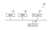
- FIG. 2 is a diagram illustrating an example of a hardware configuration of the relay device 20 according to the present embodiment.
- the relay device 20 according to the present embodiment is configured to include a control unit 21, a storage unit 22, a first input / output I / F 23, and a second input / output I / F 24.
- the control unit 21 includes a program control device such as a CPU, and executes various information processing in accordance with a program stored in the storage unit 22.
- the storage unit 22 includes memory elements such as a RAM and a ROM, and stores programs and the like executed by the control unit 21.
- the storage unit 22 also functions as a work memory of the control unit 21.
- the first input / output I / F 23 is an interface for connecting the HMD 30 to the relay device 20 such as an HDMI port or a USB port.
- the first input / output I / F 23 outputs various signals to the HMD 30 in accordance with an instruction from the control unit 21. Further, it receives a signal output from the HMD 30 and outputs the signal to the control unit 21.
- the second input / output I / F 24 is an interface for connecting the entertainment device 10 with the relay device 20 such as an HDMI port or a USB port.
- the second input / output I / F 24 outputs various signals to the entertainment apparatus 10 in accordance with an instruction from the control unit 21. Also, it receives a signal output from the entertainment apparatus 10 and outputs the signal to the control unit 21.
- the HMD 30 is a front-mounted display device that is mounted on the head of the user and presents a two-dimensional or three-dimensional image or the like to the user using a display device provided therein.
- FIG. 3 is a diagram showing an example of the hardware configuration of the HMD 30 according to the present embodiment.
- the HMD 30 according to the present embodiment includes a control unit 31, a storage unit 32, an input / output I / F 33, a display unit 34, an audio output unit 35, and a sensor unit 36.
- the control unit 31 includes a program control device such as a CPU, and executes various information processing in accordance with a program stored in the storage unit 32.
- the storage unit 32 includes memory elements such as a RAM and a ROM, and stores programs and the like executed by the control unit 31.
- the storage unit 32 also functions as a work memory of the control unit 31.
- the input / output I / F 33 is an interface for connecting the HMD 30 to the relay device 20 such as an HDMI port or a USB port, for example.
- the input / output I / F 33 outputs various signals to the relay device 20 according to an instruction from the control unit 31. Also, it receives a signal output from the relay device 20 and outputs the signal to the control unit 31.
- the display unit 34 is a display device such as a liquid crystal display or an organic EL display, for example, and displays a video represented by a video signal output from the relay device 20.
- the audio output unit 35 is, for example, a speaker, and outputs audio represented by an audio signal output from the relay device 20.
- the sensor unit 36 is a sensor such as an infrared sensor or a contact sensor, for example, and detects whether the user wears the HMD 30 or not.
- the user's face is positioned at a position facing the display unit 34 by using the infrared sensor to measure the distance to the object by detecting the reflected light obtained by irradiating the object with infrared light. By detecting whether or not to do, it is detected whether or not the user wears the HMD 30.
- a device capable of detecting the face of the user such as an imaging device such as a CCD image sensor may be provided instead of the infrared sensor.
- a contact sensor is provided at a position where the HMD 30 contacts the user while the HMD 30 is worn by the user, whether the user wears the HMD 30 is detected depending on whether the contact sensor detects a touch. You can also
- the information processing system 1 determines the time during which it is determined that the HMD 30 is worn based on the idea that the fatigue degree of the user increases according to the increase in the time when the user wears the HMD 30.
- the configuration is such that the degree of fatigue of the user is appropriately evaluated based on the accumulated cumulative wearing time.
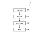
- FIG. 4 is a functional block diagram showing an example of main functions realized by the relay device 20 according to the present embodiment.
- the relay device 20 functionally includes, for example, a state determination unit 51, a count unit 52, a fatigue degree evaluation unit 53, and a notification unit 54.
- These functions are realized by the control unit 21 executing a program stored in the storage unit 22.
- the program may be provided by being stored in various computer-readable information storage media such as an optical disk, for example, or may be provided to the relay device 20 via a communication network such as the Internet.
- the state determination unit 51 obtains the detection result by the sensor unit 36 of the HMD 30, and determines the state of the HMD 30 according to the detection result at a predetermined frame rate (for example, at intervals of 1/60 seconds).
- the state of the HMD 30 determined by the state determination unit 51 in this embodiment refers to the state in which the HMD 30 is attached to the user (hereinafter referred to as the attached state) from the state in which the HMD 30 is detached from the user
- the attached state the state in which the HMD 30 is detached from the user
- the state of the HMD 30 is not changed, or the state of the HMD 30 is changed. Further, when no change occurs in the state of the HMD 30, it indicates that the attached state is maintained or the detached state is maintained.
- the state determination unit 51 determines that the detachable state changes to the wearing state, and the sensor unit 36 detects the user. When the user is not detected from the above state, it is determined that the mounting state has changed to the demounting state. Then, the state determination unit 51 changes the state of the HMD 30 when the sensor unit 36 does not detect the user again from the state where the user is not detected, or when the user is detected again from the state where the user is detected. Determine that it has not occurred.
- the state determination unit 51 determines the mounted state from the time when the user is detected while the sensor unit 36 is not detecting the user until the time when the user is not detected again, and the sensor unit 36 determines the user
- the time from when the user is not detected in the detected state to the time when the user is detected again may be determined as the detached state.
- the state determination unit 51 may determine the state of the HMD 30 based on a moving image captured by an external camera.
- an external camera connected to the entertainment apparatus 10 is installed at a position where the user can be imaged, and the state determination unit 51 is a moving image of the user photographed by the external camera via the entertainment apparatus 10 May be acquired every predetermined time. Then, the state determination unit 51 may determine the attached state or the detached state by analyzing the acquired moving image. The state determination unit 51 may obtain the result of the image analysis performed by the entertainment apparatus 10 and determine the state of the HMD 30 according to the result.
- the state determination unit 51 holds the state flag. In the present embodiment, when the HMD 30 is in the mounted state, the value of the state flag is “1”, and when the HMD 30 is in the desorbed state, the value of the state flag is “0”.
- the counting unit 52 calculates the accumulated wearing time by accumulating the time determined to be the wearing state. Then, in the present embodiment, the counting unit 52 holds accumulated wearing time data indicating the calculated cumulative wearing time. Specifically, the counting unit 52 adds the accumulated wearing time to the period determined to be the wearing state, and does not add the accumulated wearing time to the period determined to be the detached state. In addition, the counting unit 52 resets the accumulated wearing time at a predetermined timing. For example, when the accumulated wearing time exceeds a predetermined threshold (Ta), the counting unit 52 resets the accumulated wearing time.
- Ta predetermined threshold
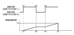
- FIG. 5A is a view showing an example of a cumulative wearing time graph according to the wearing state and the detaching state according to the present embodiment.
- FIG. 5A shows that the timing S1 has changed from the detached state (status flag "0") to the mounted status (status flag "1"), and that the period from the timing S1 to the timing S2 is the mounted status,
- the timing S2 indicates that the attachment state has changed to the detachment state
- the period from the timing S2 to the timing S3 indicates that the attachment state is in place
- the timing S3 indicates that the attachment state is changed to the attachment state. Indicates that it is in the mounted state. As shown in FIG.
- the accumulated attachment time is first added to the period determined from the wearing state (from timing S1 to timing S2) and from timing S3 to the period from which the detachment state is determined (from timing S2 to timing S3)
- the cumulative wearing time is not added. That is, the accumulated wearing time is held at a value at the time point of the timing S2 in a period (timing S2 to timing S3) determined to be in the detached state. Then, the accumulated wearing time is reset at timing Sa at which the cumulative wearing time exceeds a predetermined threshold (Ta).
- the counting unit 52 may reset the accumulated wearing time when it is determined that the wearing state is changed to the detaching state.
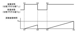
- FIG. 5B is a view showing an example of a cumulative wearing time graph according to the wearing state and the detaching state according to the present embodiment.
- FIG. 5B shows that the timing S1 has changed from the detachment state to the wearing state, shows that the period from the timing S1 to the timing S2 is the wearing state, and the timing S2 shows that it has changed from the wearing state to the detachment state
- the period from the timing S2 to the timing S3 indicates that it is in the detached state
- the timing S3 indicates that it has changed from the detached state to the attached state, and indicates that it is in the attached state after timing S3.
- the accumulated wearing time is added to the period (timing S1 to timing S2) determined to be in the wearing state.
- the accumulated wearing time is reset at timing S2 when the wearing state changes to the detaching state. Then, the accumulated wearing time is not added in a period (timing S2 to timing S3) determined to be in the detached state. That is, the accumulated attachment time is held in a reset state during a period (timing S2 to timing S3) determined to be in the detached state. Then, after the timing S3 when the detachable state changes to the attached state, the reset accumulated attached time is added again. It is assumed that the accumulated wearing time is also reset at timing Sa at which the accumulated wearing time exceeds the predetermined threshold (Ta) in FIG. 5B.
- the counting unit 52 may further calculate the accumulated desorption time by accumulating periods determined to be in the desorption state. Then, the counting unit 52 may reset the accumulated wearing time when the accumulated desorption time exceeds the predetermined threshold (Td). Also, in this case, the counting unit 52 holds accumulated desorption time data indicating the calculated accumulated desorption time.
- the user's fatigue level is considered to decrease according to the cumulative desorption time, that is, the rest time when the HMD 30 is not used. Therefore, if the cumulative desorption time exceeds a predetermined threshold considered to be a sufficient rest time, cumulative wearing I'm going to reset the time.
- FIG. 5C is a view showing an example of a cumulative wearing time graph according to the wearing state and the detaching state according to the present embodiment.
- FIG. 5C shows that timing S1 has changed from the detached state to the mounted state, that the period from timing S1 to timing S2 is in the mounted state, and timing S2 shows that it has changed from the mounted state to the detached state.
- the period from the timing S2 to the timing S3 indicates that it is in the detached state
- the timing S3 indicates that it has changed from the detached state to the attached state, and indicates that it is in the attached state after timing S3.
- the accumulated wearing time is added to the period (timing S1 to timing S2) determined to be in the wearing state.
- the accumulated desorption time is added during the period determined as the desorption state (timing S2 to timing S3), and the accumulated wearing time is not added during that time. Then, the accumulated wearing time is reset at timing Sd at which the accumulated desorption time exceeds the predetermined threshold (Td). Then, after timing S3 when the detachable state changes to the attached state, the accumulated attached time is added again from the reset state. The accumulated desorption time is reset at timing S3 when the desorption state changes to the wearing state. In FIG. 5C, it is assumed that the cumulative wearing time is also reset at timing Sa at which the cumulative wearing time exceeds a predetermined threshold (Ta).
- the accumulated desorption time may be reset at timing Sd at which the accumulated desorption time exceeds a predetermined threshold (Td).
- Td a predetermined threshold
- the cumulative desorption time is not reset at the timing at which it changes from the desorption state to the wearing state, and the period determined as the wearing state is held at a value at the timing at which the cumulative wearing time changes from the desorption state to the wearing state. It may be
- the counting unit 52 may subtract the accumulated wearing time during a period determined to be in the detached state.
- the cumulative wearing time since it is considered that the user's fatigue level decreases according to the cumulative desorption time, that is, the rest time when the HMD 30 is not used, the cumulative wearing time is subtracted according to the cumulative desorption time. That is, since the accumulated wearing time is reduced more as the accumulated desorption time is longer, the user's fatigue degree is easily evaluated to be low in the user's fatigue degree evaluation processing by the fatigue degree evaluating unit 53 described later.
- FIG. 5D is a view showing an example of a cumulative wearing time graph according to the wearing state and the detaching state according to the present embodiment.
- FIG. 5D shows that the timing S1 has changed from the detachable state to the mounted state, the period from the timing S1 to the timing S2 is in the mounted state, and the timing S2 shows that the period from the mounted state to the detached state.
- the period from the timing S2 to the timing S3 indicates that it is in the detached state, the timing S3 indicates that it has changed from the detached state to the attached state, and indicates that it is in the attached state after timing S3.
- the accumulated wearing time is added to the period (timing S1 to timing S2) determined to be in the wearing state.
- the accumulated wearing time is subtracted from the period (timing S2 to timing S3) determined to be in the desorbed state. Then, after the timing S3 at which it is determined that the wearing state is set, the cumulative wearing time is added again. It is assumed that the accumulated wearing time is reset also at timing Sa at which the accumulated wearing time exceeds the predetermined threshold (Ta) in FIG. 5D.
- the fatigue degree evaluation unit 53 evaluates the fatigue degree of the user wearing the HMD 30 based on the accumulated wearing time calculated by the counting unit 52.
- the fatigue level evaluation unit 53 in the present embodiment uses the cumulative wearing time as an index of the fatigue level of the user, and the fatigue level is higher as the cumulative wearing time is longer than a predetermined threshold (Ta), and the cumulative wearing time is a predetermined threshold It can be evaluated that the fatigue degree is lower as it is shorter than (Ta).
- the fatigue degree evaluation unit 53 in the present embodiment monitors, at a predetermined frame rate, whether the accumulated wearing time calculated by the counting unit 52 exceeds the predetermined threshold (Ta) as described above.
- the notification unit 54 notifies the user according to the user's degree of fatigue evaluated by the fatigue degree evaluation unit 53. Specifically, the notification unit 54 causes the HMD 30 to output a predetermined notification when it is determined by the fatigue degree evaluation unit 53 that the accumulated wearing time exceeds the predetermined threshold (Ta). Then, after the notification unit 54 causes the HMD 30 to output a predetermined notification, the cumulative attachment time is reset.
- the notification performed by the notification unit 54 may be a notification that causes the user to notice his or her own fatigue, and for example, the voice or image that “the usage time has exceeded Ta (for example, 2 hours)” is the HMD 30.
- the warning lamp provided in the HMD 30 may be turned on.
- the notification unit 54 may cause the HMD 30 to output a stepwise notification according to the accumulated wearing time. For example, when the cumulative wearing time exceeds the first time T1, that is, when the fatigue degree evaluation unit 53 evaluates the fatigue degree as small, the first notification, when the cumulative wearing time exceeds the second time T2, That is, the second notification when the fatigue degree evaluation unit 54 evaluates as being in the fatigue degree, the cumulative wearing time exceeds the third time T3, that is, when the fatigue degree evaluation unit 54 evaluates as the fatigue degree is large
- the notification 3 may be output to the HMD 30. In this case, for example, sound is output to the HMD 30 as the first notification, an image is output to the HMD 30 as the second notification, and operation is restricted in the game played by the user as the third notification.
- the notification may be performed by different means in stages as an etc.
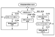
- the state determination unit 51 monitors the state of the HMD 30 (S101).
- the state determination unit 51 determines whether or not a change has occurred in the state of the HMD 30 at a predetermined frame rate (hereinafter, referred to as a state monitoring cycle time). That is, the state determination unit 51 determines one of the change from the removal state to the attachment state, the change from the attachment state to the removal state, and the change in the state of the HMD 30.
- the state determination unit 51 determines the value of the state flag (S103).
- the counting unit 52 adds a predetermined time to the accumulated wearing time (S104).
- the counting unit 52 adds the state monitoring cycle time in the process S101. That is, counting unit 52 adds an elapsed time from the time when the determination process by state determination unit 51 in the previous process S101 is performed to the time when the determination process by state determination unit 51 in this process S101 is performed. .
- the predetermined time to be added to the accumulated wearing time is not limited to the state monitoring cycle time, and may be set to an appropriately set time. Thereafter, the process returns to step S101 and the subsequent steps are repeatedly executed.
- the state determination unit 51 determines that the HMD 30 has changed from the detached state to the attached state in the process S101, the state determination unit 51 updates the value of the state flag to "1" (S102). Thereafter, the process returns to step S101 to execute the subsequent processes.
- the state determination unit 51 determines that the HMD 30 has changed from the attached state to the detached state in processing S101, the state determination unit 51 updates the value of the state flag to “0” (S105).
- the counting unit 52 determines, for example, whether or not to reset the accumulated wearing time according to the value of the state flag.
- the counting unit 52 determines that the accumulated wearing time is reset when the value of the state flag is “0”, and determines that the accumulated wearing time is not reset when the value of the state flag is “1”.
- step S105 If it is determined in step S105 that the accumulated wearing time is to be reset (S106: Y), the counting unit 52 resets the accumulated wearing time (S107). If it is determined in the process S106 that the accumulated attachment time is not reset (S106: N), the process returns to the process S101 and the subsequent processes are repeatedly executed.
- the processing from the processing S101 to the processing S107 is repeatedly executed at a predetermined frame rate.
- the process S106 and the process S107 may be omitted.
- the state determination unit 51 updates the state flag to “0” in the process S105
- the accumulated attachment time may not be reset before returning to the process S101. That is, in this case, it corresponds to the accumulated wearing time graph shown in FIG. 5A, and the accumulated wearing time is held without being reset during a period determined to be in the detached state.
- the state determination unit 51 updates the state flag to “0” in the process S105, whether or not to reset the cumulative attachment time may be settable before returning to the process S101.
- the cumulative wearing time is added to the period determined to be the wearing state, and the cumulative wearing time is not added to the period determined to be the demounting state. Therefore, even if the HMD 30 is attached or detached while the power of the HMD 30 is ON, the cumulative attachment time is added only during the period determined as the attached state, and the time during which the HMD 30 is actually attached is appropriate It is possible to calculate
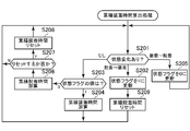
- the counting unit 52 adds a predetermined time to the accumulated desorption time (S206).
- the counting unit 52 may add the state monitoring cycle time in the process S201 or may add an appropriately set time.
- the counting unit 52 determines whether the counting unit 52 resets the accumulated wearing time (S207).
- the counting unit 52 determines whether to reset the accumulated wearing time according to the accumulated desorption time. In this case, counting unit 52 determines that the accumulated attachment time is reset when the accumulated desorption time exceeds the predetermined threshold (Td), and resets the accumulated attachment time when the accumulated desorption time is equal to or less than the predetermined threshold (Td). I will not judge.
- step S207 If it is determined in step S207 that the accumulated attachment time is to be reset (S207: Y), the counting unit 52 resets the accumulated attachment time (S208). after that. The processing returns to step S201 and the subsequent processing is repeatedly executed. If it is determined that the cumulative attachment time is not reset in the process S207 (S207: N), the process returns to the process S201 and the subsequent processes are repeatedly executed.
- the counting unit 52 resets the accumulated desorption time (S209). Thereafter, the process returns to step S201 and the subsequent steps are repeatedly executed.
- the processing from the processing S201 to the processing S209 is repeatedly executed at a predetermined frame rate.
- step S209 the process of step S209 may be executed in step S208. Specifically, if it is determined in step S207 that the accumulated wearing time is reset (S207: Y), the counting unit 52 may reset the accumulated wearing time and the accumulated desorption time in step S208. In this case, since the accumulated desorption time is not reset when the status flag is updated to 1 in the processing S202, the accumulated desorption time is held during a period in which the HMD 30 is determined to be attached, and then the HMD 30 is detached In the period determined to be determined, a predetermined time is added to the held accumulated desorption time.
- the cumulative wearing time is added to the period determined to be the wearing state, and the cumulative wearing time is not added to the period determined to be the detachable state and the cumulative desorption time is added. Then, the cumulative attachment time is reset according to the calculated cumulative desorption time. Therefore, even if the HMD 30 is attached or detached while the power of the HMD 30 is ON, it is possible to properly calculate the time during which the HMD 30 is actually attached, and cumulative attachment according to the cumulative detachment time. It becomes possible to control time.
- the counting unit 52 may subtract a predetermined time from the cumulative wearing time. In this case, it corresponds to the accumulated wearing time graph shown in FIG. 5D.
- the counting unit 52 may subtract the state monitoring cycle time (Tc) from the cumulative wearing time, or may subtract a ⁇ Tc (where a is a coefficient less than 1) from the cumulative wearing time. It is also possible to subtract the time set as appropriate. As a result, it is possible to calculate the cumulative wearing time in consideration of the cumulative desorption time.
- the fatigue degree evaluating unit 53 adds the predetermined cumulative wearing time to the predetermined threshold (Ta). It may be determined whether it exceeds or not. Then, the notification unit 54 may cause the HMD 30 to output a predetermined notification when the fatigue degree evaluation unit 53 determines that the accumulated cumulative wearing time exceeds the predetermined threshold (Ta).
- the sensor unit of the HMD 30 includes imaging devices such as a CCD image sensor, a CMOS image sensor, and an infrared image sensor, and captures a face image of the user when the HMD 30 is attached to the user. Then, the state determination unit 51 identifies the user wearing the HMD 30 from feature information extracted from the face image of the user captured using a known face recognition technology or iris recognition technology.
- the identification of the user wearing the HMD 30 is not limited to the above example.
- the user can be identified using feature information extracted by known voice recognition from the voice emitted by the user collected by the microphone unit provided in the HMD 30 The identification may be performed, or the user may be identified by causing the user wearing the HMD 30 to perform a login operation.
- the user may be identified using an image of the user captured by an external camera unit.
- user information in which the feature information is associated with personal information (user name, password, name, age, etc.) of the user is registered in advance in the entertainment apparatus 10, and the state determination unit 51 is registered.
- the user name and the like of the user who wears the HMD 30 can be specified by referring to the existing user information.
- the user information may be registered in the relay device 20, the HMD 30, or another server.
- the state determination unit 51 holds the mounting user information together with the state flag.
- the mounting user information information indicating the user who is wearing the HMD 30 is stored during the period when the HMD 30 is determined to be in the mounting state, and the user name and the like obtained from the above user information are stored Good.
- the state determination unit 51 determines that the attachment state has been changed from the detached state, the state determination unit 51 performs the HMD 30 by the method as described above.
- the state determination unit 51 updates the value of the state flag to “1”, and information (for example, user name) indicating the user who specified the mounting user information. Update to
- the counting unit 52 holds accumulated attachment time data in association with information indicating the user. Specifically, when it is determined that the value of the status flag is “1” in the process S103 of FIG. 6 or the process S203 of FIG. 7, the state determination unit 51 determines the user held in the mounted user information. The information to be shown shall be determined. Then, in the process S104 of FIG. 6 or the process S204 of FIG. 7, the counting unit 52 adds the cumulative wearing time using the cumulative wearing time data associated with the information indicating the user determined by the state determining unit 51. Do.
- the state determination unit 51 identifies the user who wears the HMD 30. However, in order to calculate the cumulative wearing time for each user, it is only necessary to be able to identify the user wearing the HMD 30. That is, even if the user wearing the HMD 30 is not specified, it is only necessary to distinguish between the plurality of users wearing the HMD 30. For example, the state determination unit 51 adds a plurality of identifiers such as a first user, a second user, and a third user to the feature information extracted from the face image of the user captured by the sensor unit 36 of the HMD 30. You may distinguish the users of.
- the state determination unit 51 may extract feature information (for example, clothing color, physique, etc.) that can distinguish a plurality of users from an image of a user captured by an external camera unit and assign an identifier.
- the identifier is stored in the wearing user information held by the state determination unit 51, and the counting unit 52 holds accumulated wearing time data in association with the identifier.
- the fatigue degree of the user using the HMD 30 is evaluated based on the cumulative wearing time, on the assumption that the fatigue degree of the user using the HMD 30 increases according to the increase of the cumulative wearing time.
- the user's fatigue degree may be different depending on the display content of the HMD 30, the attribute of the user using the HMD 30, etc. without being limited to the example where the user's fatigue degree increases with the increase of the cumulative wearing time.
- the user who wears the HMD 30 has the same wearing time but is viewing the 3D video is the user's
- the degree of fatigue is considered to be high.
- the user's fatigue degree can not be properly evaluated simply by evaluating the user's fatigue degree based on the cumulative wearing time that accumulates only the time determined to be the wearing state.
- the degree of fatigue of the user may be evaluated based on information of the user wearing the HMD 30, a video displayed on the HMD 30, and the like in a period determined to be the wearing state.
- the counting unit 52 adds a predetermined time to the accumulated wearing time
- the predetermined time to be added may be controlled according to various conditions (user information, display image of the HMD 30, etc.).
- the counting unit 52 may obtain user information on the user specified by the state determination unit 51 as described above, and control a predetermined time for addition according to the user information. For example, when the age of the identified user satisfies a predetermined condition (for example, under 15 years old, over 65 years old, etc.), the counting unit 52 calculates b ⁇ Tc (b is a coefficient larger than 1) in the cumulative wearing time. It is also possible to add. As a result, the user corresponding to the degree of fatigue of the user is more likely to be notified to the user of the young or old who is likely to accumulate fatigue by using the HMD 30.
- a predetermined condition for example, under 15 years old, over 65 years old, etc.
- the counting unit 52 calculates d ⁇ Tc (d is a coefficient smaller than 1) as the cumulative wearing time. It is also possible to add. As a result, it is difficult for a user of a general age who uses the HMD 30 to receive a notification according to the degree of fatigue of the user than the user of the younger generation and the elderly.
- information on an application used by the user may be acquired during a period in which the HMD 30 is attached, and a predetermined time added by the counting unit 52 may be controlled according to the used application.
- the counting unit 52 calculates b ⁇ Tc (cumulative wearing time). b may be added as a coefficient larger than 1).
- the counting unit 52 calculates b ⁇ Tc (b is 1 A larger coefficient may be added.
- the counting unit 52 adds d ⁇ Tc (d is a coefficient smaller than 1) to the accumulated wearing time. It may be As a result, it is difficult for a user who is viewing a two-dimensional video or the like, in which fatigue is relatively difficult to be accumulated, to be notified more easily than a user viewing a three-dimensional video according to the degree of fatigue of the user.
- the application acquires information of an application being executed by the entertainment apparatus 10 from the entertainment apparatus 10, and is an application including a video with a lot of motion, a lot of flickering videos, and a video that is relatively easy to accumulate fatigue. If it is determined that there is, the counting unit 52 may add b ⁇ Tc (b is a coefficient larger than 1) to the cumulative wearing time.
- the application including a video that is relatively easy to accumulate fatigue may be a game application, or an application of a competition game or a race game application that is considered to be particularly easy to accumulate fatigue among game applications.
- the counting unit 52 may add d ⁇ Tc (d is a coefficient smaller than 1) to the cumulative wearing time.
- the counting unit 52 may add b ⁇ Tc (b is a coefficient larger than 1) to the accumulated wearing time.
- the present invention is not limited to the above-described embodiment.
- part or all of the functions realized by the relay device 20 according to the present embodiment shown in FIG. 4 may be implemented in the entertainment apparatus 10 or in the HMD 30.
- the functions illustrated in FIG. 4 may be distributed and implemented in the entertainment apparatus 10, the relay apparatus 20, or the HMD 30.
Landscapes
- Engineering & Computer Science (AREA)
- Physics & Mathematics (AREA)
- General Physics & Mathematics (AREA)
- Health & Medical Sciences (AREA)
- Computer Hardware Design (AREA)
- Theoretical Computer Science (AREA)
- Life Sciences & Earth Sciences (AREA)
- Optics & Photonics (AREA)
- Multimedia (AREA)
- Signal Processing (AREA)
- Emergency Management (AREA)
- Medical Informatics (AREA)
- Business, Economics & Management (AREA)
- Biophysics (AREA)
- Pathology (AREA)
- Biomedical Technology (AREA)
- Heart & Thoracic Surgery (AREA)
- Physiology (AREA)
- Molecular Biology (AREA)
- Surgery (AREA)
- Animal Behavior & Ethology (AREA)
- General Health & Medical Sciences (AREA)
- Public Health (AREA)
- Veterinary Medicine (AREA)
- User Interface Of Digital Computer (AREA)
- Controls And Circuits For Display Device (AREA)
Abstract
Priority Applications (3)
| Application Number | Priority Date | Filing Date | Title |
|---|---|---|---|
| JP2017529576A JPWO2017014135A1 (ja) | 2015-07-21 | 2016-07-14 | 情報処理装置、疲労度評価方法、及びプログラム |
| EP16827695.4A EP3327717A4 (fr) | 2015-07-21 | 2016-07-14 | Dispositif de traitement d'informations, procédé d'évaluation de niveau de fatigue, et programme |
| US15/736,940 US20180299671A1 (en) | 2015-07-21 | 2016-07-14 | Information processing apparatus, fatigue degree evaluating method, and program |
Applications Claiming Priority (2)
| Application Number | Priority Date | Filing Date | Title |
|---|---|---|---|
| JP2015-143616 | 2015-07-21 | ||
| JP2015143616 | 2015-07-21 |
Publications (1)
| Publication Number | Publication Date |
|---|---|
| WO2017014135A1 true WO2017014135A1 (fr) | 2017-01-26 |
Family
ID=57835005
Family Applications (1)
| Application Number | Title | Priority Date | Filing Date |
|---|---|---|---|
| PCT/JP2016/070786 Ceased WO2017014135A1 (fr) | 2015-07-21 | 2016-07-14 | Dispositif de traitement d'informations, procédé d'évaluation de niveau de fatigue, et programme |
Country Status (4)
| Country | Link |
|---|---|
| US (1) | US20180299671A1 (fr) |
| EP (1) | EP3327717A4 (fr) |
| JP (1) | JPWO2017014135A1 (fr) |
| WO (1) | WO2017014135A1 (fr) |
Cited By (5)
| Publication number | Priority date | Publication date | Assignee | Title |
|---|---|---|---|---|
| JP2019101811A (ja) * | 2017-12-04 | 2019-06-24 | 富士通株式会社 | 処理プログラム、処理方法及び処理装置、並びに表示プログラム、表示方法及び表示制御装置 |
| JP2019114930A (ja) * | 2017-12-22 | 2019-07-11 | 株式会社セガゲームス | 情報処理装置及びプログラム |
| JP2020067610A (ja) * | 2018-10-26 | 2020-04-30 | Necパーソナルコンピュータ株式会社 | 電子機器 |
| KR102248123B1 (ko) * | 2019-11-13 | 2021-05-04 | 충남대학교산학협력단 | 피로도 조절 안경 |
| JP2022097292A (ja) * | 2020-12-18 | 2022-06-30 | ヤフー株式会社 | 情報処理装置、情報処理方法、及び情報処理プログラム |
Families Citing this family (2)
| Publication number | Priority date | Publication date | Assignee | Title |
|---|---|---|---|---|
| US20230221566A1 (en) * | 2022-01-08 | 2023-07-13 | Sony Interactive Entertainment Inc. | Vr headset with integrated thermal/motion sensors |
| CN115460495B (zh) * | 2022-09-13 | 2025-05-16 | 深圳市宇通联发科技有限公司 | 耳机提示方法、装置、耳机及存储介质 |
Citations (4)
| Publication number | Priority date | Publication date | Assignee | Title |
|---|---|---|---|---|
| JPH03124226U (fr) * | 1990-03-28 | 1991-12-17 | ||
| JP2001145045A (ja) * | 2000-09-11 | 2001-05-25 | Olympus Optical Co Ltd | 映像表示装置 |
| JP2001216363A (ja) * | 2000-02-04 | 2001-08-10 | Fujitsu Ltd | コンピュータ装置オペレータの疲労解消支援システム及びそのシステムでの処理をコンピュータに行なわせるためのプログラムを格納した記憶媒体 |
| JP2005071169A (ja) * | 2003-08-26 | 2005-03-17 | Daikin Ind Ltd | 作業管理システム、作業者検知装置、入力検知装置、積算装置、報知装置、エリア別環境提供装置及び作業管理方法 |
Family Cites Families (7)
| Publication number | Priority date | Publication date | Assignee | Title |
|---|---|---|---|---|
| JPH05166026A (ja) * | 1991-12-18 | 1993-07-02 | Mitsubishi Motors Corp | ビデオ作業時間監視タイマ |
| JP4041266B2 (ja) * | 2000-05-29 | 2008-01-30 | シャープ株式会社 | コンテンツ再生装置及び方法、並びにコンテンツ再生プログラムを記録した記録媒体 |
| JP2006173696A (ja) * | 2004-12-13 | 2006-06-29 | Matsushita Electric Ind Co Ltd | ディスプレイ装置 |
| JP4992355B2 (ja) * | 2006-09-13 | 2012-08-08 | 株式会社ニコン | 頭部装着型ディスプレイ |
| JP2008257671A (ja) * | 2007-03-15 | 2008-10-23 | Canon Inc | 情報処理装置及び情報処理方法 |
| JP2011033707A (ja) * | 2009-07-30 | 2011-02-17 | Canon Inc | 画像処理装置及びその制御方法 |
| JP2014103585A (ja) * | 2012-11-21 | 2014-06-05 | Toshiba Corp | 立体画像表示装置 |
-
2016
- 2016-07-14 WO PCT/JP2016/070786 patent/WO2017014135A1/fr not_active Ceased
- 2016-07-14 JP JP2017529576A patent/JPWO2017014135A1/ja active Pending
- 2016-07-14 US US15/736,940 patent/US20180299671A1/en not_active Abandoned
- 2016-07-14 EP EP16827695.4A patent/EP3327717A4/fr not_active Ceased
Patent Citations (4)
| Publication number | Priority date | Publication date | Assignee | Title |
|---|---|---|---|---|
| JPH03124226U (fr) * | 1990-03-28 | 1991-12-17 | ||
| JP2001216363A (ja) * | 2000-02-04 | 2001-08-10 | Fujitsu Ltd | コンピュータ装置オペレータの疲労解消支援システム及びそのシステムでの処理をコンピュータに行なわせるためのプログラムを格納した記憶媒体 |
| JP2001145045A (ja) * | 2000-09-11 | 2001-05-25 | Olympus Optical Co Ltd | 映像表示装置 |
| JP2005071169A (ja) * | 2003-08-26 | 2005-03-17 | Daikin Ind Ltd | 作業管理システム、作業者検知装置、入力検知装置、積算装置、報知装置、エリア別環境提供装置及び作業管理方法 |
Non-Patent Citations (1)
| Title |
|---|
| See also references of EP3327717A4 * |
Cited By (6)
| Publication number | Priority date | Publication date | Assignee | Title |
|---|---|---|---|---|
| JP2019101811A (ja) * | 2017-12-04 | 2019-06-24 | 富士通株式会社 | 処理プログラム、処理方法及び処理装置、並びに表示プログラム、表示方法及び表示制御装置 |
| JP2019114930A (ja) * | 2017-12-22 | 2019-07-11 | 株式会社セガゲームス | 情報処理装置及びプログラム |
| JP2020067610A (ja) * | 2018-10-26 | 2020-04-30 | Necパーソナルコンピュータ株式会社 | 電子機器 |
| KR102248123B1 (ko) * | 2019-11-13 | 2021-05-04 | 충남대학교산학협력단 | 피로도 조절 안경 |
| JP2022097292A (ja) * | 2020-12-18 | 2022-06-30 | ヤフー株式会社 | 情報処理装置、情報処理方法、及び情報処理プログラム |
| JP7110314B2 (ja) | 2020-12-18 | 2022-08-01 | ヤフー株式会社 | 情報処理装置、情報処理方法、及び情報処理プログラム |
Also Published As
| Publication number | Publication date |
|---|---|
| EP3327717A1 (fr) | 2018-05-30 |
| JPWO2017014135A1 (ja) | 2018-04-26 |
| US20180299671A1 (en) | 2018-10-18 |
| EP3327717A4 (fr) | 2019-04-24 |
Similar Documents
| Publication | Publication Date | Title |
|---|---|---|
| WO2017014135A1 (fr) | Dispositif de traitement d'informations, procédé d'évaluation de niveau de fatigue, et programme | |
| JP6741130B2 (ja) | 情報処理システム、情報処理方法及びプログラム | |
| CN103702155B (zh) | 一种电视控制方法及装置 | |
| CN104835274B (zh) | 一种可穿戴设备的防盗方法、装置以及可穿戴设备 | |
| CN103927250B (zh) | 一种终端设备用户姿态检测方法 | |
| RU2018103060A (ru) | Способы и системы для извлечения характеристик движения пользователя с использованием датчика холла для предоставления пользователю обратной связи | |
| US10359839B2 (en) | Performing output control based on user behaviour | |
| JP2017507400A5 (fr) | ||
| CN106098020A (zh) | 控制方法及控制装置 | |
| JP2013504933A5 (fr) | ||
| JP2018519007A5 (fr) | ||
| JP2013031167A5 (fr) | ||
| TW201743166A (zh) | 護眼系統及方法 | |
| US20170127235A1 (en) | Information processing apparatus, information processing method, and program | |
| JP6492330B2 (ja) | 電子機器、および画像の提供方法 | |
| CN105814518A (zh) | 一种信息处理方法以及智能手环 | |
| JP2012034343A5 (ja) | 画像処理装置、及びその制御方法 | |
| TW201207778A (en) | Monitoring system and related recording methods for recording motioned image, and machine readable medium thereof | |
| JP6383875B2 (ja) | ヘッドマウントディスプレイ、通知装置、通知システム、通知方法及びプログラム | |
| JP2013101524A5 (fr) | ||
| US10569135B2 (en) | Analysis device, recording medium, and analysis method | |
| CN104243803A (zh) | 信息处理设备、信息处理方法和程序 | |
| TWI384383B (zh) | 視線察覺裝置及其方法 | |
| JP6720960B2 (ja) | 撮像制御装置、撮像制御方法および撮像制御システム | |
| CN105959768A (zh) | 视频播放参数配置方法及设备 |
Legal Events
| Date | Code | Title | Description |
|---|---|---|---|
| 121 | Ep: the epo has been informed by wipo that ep was designated in this application |
Ref document number: 16827695 Country of ref document: EP Kind code of ref document: A1 |
|
| ENP | Entry into the national phase |
Ref document number: 2017529576 Country of ref document: JP Kind code of ref document: A |
|
| WWE | Wipo information: entry into national phase |
Ref document number: 15736940 Country of ref document: US |
|
| NENP | Non-entry into the national phase |
Ref country code: DE |
|
| WWE | Wipo information: entry into national phase |
Ref document number: 2016827695 Country of ref document: EP |