WO2017014139A1 - Segment de piston et procédé de fabrication pour ce dernier - Google Patents
Segment de piston et procédé de fabrication pour ce dernier Download PDFInfo
- Publication number
- WO2017014139A1 WO2017014139A1 PCT/JP2016/070809 JP2016070809W WO2017014139A1 WO 2017014139 A1 WO2017014139 A1 WO 2017014139A1 JP 2016070809 W JP2016070809 W JP 2016070809W WO 2017014139 A1 WO2017014139 A1 WO 2017014139A1
- Authority
- WO
- WIPO (PCT)
- Prior art keywords
- piston ring
- ring according
- treatment
- phosphate
- chemical conversion
- Prior art date
- Legal status (The legal status is an assumption and is not a legal conclusion. Google has not performed a legal analysis and makes no representation as to the accuracy of the status listed.)
- Ceased
Links
Images



Classifications
-
- F—MECHANICAL ENGINEERING; LIGHTING; HEATING; WEAPONS; BLASTING
- F16—ENGINEERING ELEMENTS AND UNITS; GENERAL MEASURES FOR PRODUCING AND MAINTAINING EFFECTIVE FUNCTIONING OF MACHINES OR INSTALLATIONS; THERMAL INSULATION IN GENERAL
- F16J—PISTONS; CYLINDERS; SEALINGS
- F16J9/00—Piston-rings, e.g. non-metallic piston-rings, seats therefor; Ring sealings of similar construction
- F16J9/12—Details
- F16J9/22—Rings for preventing wear of grooves or like seatings
-
- C—CHEMISTRY; METALLURGY
- C23—COATING METALLIC MATERIAL; COATING MATERIAL WITH METALLIC MATERIAL; CHEMICAL SURFACE TREATMENT; DIFFUSION TREATMENT OF METALLIC MATERIAL; COATING BY VACUUM EVAPORATION, BY SPUTTERING, BY ION IMPLANTATION OR BY CHEMICAL VAPOUR DEPOSITION, IN GENERAL; INHIBITING CORROSION OF METALLIC MATERIAL OR INCRUSTATION IN GENERAL
- C23C—COATING METALLIC MATERIAL; COATING MATERIAL WITH METALLIC MATERIAL; SURFACE TREATMENT OF METALLIC MATERIAL BY DIFFUSION INTO THE SURFACE, BY CHEMICAL CONVERSION OR SUBSTITUTION; COATING BY VACUUM EVAPORATION, BY SPUTTERING, BY ION IMPLANTATION OR BY CHEMICAL VAPOUR DEPOSITION, IN GENERAL
- C23C22/00—Chemical surface treatment of metallic material by reaction of the surface with a reactive liquid, leaving reaction products of surface material in the coating, e.g. conversion coatings, passivation of metals
- C23C22/05—Chemical surface treatment of metallic material by reaction of the surface with a reactive liquid, leaving reaction products of surface material in the coating, e.g. conversion coatings, passivation of metals using aqueous solutions
- C23C22/06—Chemical surface treatment of metallic material by reaction of the surface with a reactive liquid, leaving reaction products of surface material in the coating, e.g. conversion coatings, passivation of metals using aqueous solutions using aqueous acidic solutions with pH less than 6
- C23C22/07—Chemical surface treatment of metallic material by reaction of the surface with a reactive liquid, leaving reaction products of surface material in the coating, e.g. conversion coatings, passivation of metals using aqueous solutions using aqueous acidic solutions with pH less than 6 containing phosphates
- C23C22/08—Orthophosphates
- C23C22/22—Orthophosphates containing alkaline earth metal cations
-
- C—CHEMISTRY; METALLURGY
- C23—COATING METALLIC MATERIAL; COATING MATERIAL WITH METALLIC MATERIAL; CHEMICAL SURFACE TREATMENT; DIFFUSION TREATMENT OF METALLIC MATERIAL; COATING BY VACUUM EVAPORATION, BY SPUTTERING, BY ION IMPLANTATION OR BY CHEMICAL VAPOUR DEPOSITION, IN GENERAL; INHIBITING CORROSION OF METALLIC MATERIAL OR INCRUSTATION IN GENERAL
- C23C—COATING METALLIC MATERIAL; COATING MATERIAL WITH METALLIC MATERIAL; SURFACE TREATMENT OF METALLIC MATERIAL BY DIFFUSION INTO THE SURFACE, BY CHEMICAL CONVERSION OR SUBSTITUTION; COATING BY VACUUM EVAPORATION, BY SPUTTERING, BY ION IMPLANTATION OR BY CHEMICAL VAPOUR DEPOSITION, IN GENERAL
- C23C28/00—Coating for obtaining at least two superposed coatings either by methods not provided for in a single one of groups C23C2/00 - C23C26/00 or by combinations of methods provided for in subclasses C23C and C25C or C25D
- C23C28/04—Coating for obtaining at least two superposed coatings either by methods not provided for in a single one of groups C23C2/00 - C23C26/00 or by combinations of methods provided for in subclasses C23C and C25C or C25D only coatings of inorganic non-metallic material
-
- C—CHEMISTRY; METALLURGY
- C23—COATING METALLIC MATERIAL; COATING MATERIAL WITH METALLIC MATERIAL; CHEMICAL SURFACE TREATMENT; DIFFUSION TREATMENT OF METALLIC MATERIAL; COATING BY VACUUM EVAPORATION, BY SPUTTERING, BY ION IMPLANTATION OR BY CHEMICAL VAPOUR DEPOSITION, IN GENERAL; INHIBITING CORROSION OF METALLIC MATERIAL OR INCRUSTATION IN GENERAL
- C23C—COATING METALLIC MATERIAL; COATING MATERIAL WITH METALLIC MATERIAL; SURFACE TREATMENT OF METALLIC MATERIAL BY DIFFUSION INTO THE SURFACE, BY CHEMICAL CONVERSION OR SUBSTITUTION; COATING BY VACUUM EVAPORATION, BY SPUTTERING, BY ION IMPLANTATION OR BY CHEMICAL VAPOUR DEPOSITION, IN GENERAL
- C23C8/00—Solid state diffusion of only non-metal elements into metallic material surfaces; Chemical surface treatment of metallic material by reaction of the surface with a reactive gas, leaving reaction products of surface material in the coating, e.g. conversion coatings, passivation of metals
- C23C8/06—Solid state diffusion of only non-metal elements into metallic material surfaces; Chemical surface treatment of metallic material by reaction of the surface with a reactive gas, leaving reaction products of surface material in the coating, e.g. conversion coatings, passivation of metals using gases
- C23C8/08—Solid state diffusion of only non-metal elements into metallic material surfaces; Chemical surface treatment of metallic material by reaction of the surface with a reactive gas, leaving reaction products of surface material in the coating, e.g. conversion coatings, passivation of metals using gases only one element being applied
- C23C8/24—Nitriding
- C23C8/26—Nitriding of ferrous surfaces
-
- C—CHEMISTRY; METALLURGY
- C23—COATING METALLIC MATERIAL; COATING MATERIAL WITH METALLIC MATERIAL; CHEMICAL SURFACE TREATMENT; DIFFUSION TREATMENT OF METALLIC MATERIAL; COATING BY VACUUM EVAPORATION, BY SPUTTERING, BY ION IMPLANTATION OR BY CHEMICAL VAPOUR DEPOSITION, IN GENERAL; INHIBITING CORROSION OF METALLIC MATERIAL OR INCRUSTATION IN GENERAL
- C23C—COATING METALLIC MATERIAL; COATING MATERIAL WITH METALLIC MATERIAL; SURFACE TREATMENT OF METALLIC MATERIAL BY DIFFUSION INTO THE SURFACE, BY CHEMICAL CONVERSION OR SUBSTITUTION; COATING BY VACUUM EVAPORATION, BY SPUTTERING, BY ION IMPLANTATION OR BY CHEMICAL VAPOUR DEPOSITION, IN GENERAL
- C23C8/00—Solid state diffusion of only non-metal elements into metallic material surfaces; Chemical surface treatment of metallic material by reaction of the surface with a reactive gas, leaving reaction products of surface material in the coating, e.g. conversion coatings, passivation of metals
- C23C8/06—Solid state diffusion of only non-metal elements into metallic material surfaces; Chemical surface treatment of metallic material by reaction of the surface with a reactive gas, leaving reaction products of surface material in the coating, e.g. conversion coatings, passivation of metals using gases
- C23C8/36—Solid state diffusion of only non-metal elements into metallic material surfaces; Chemical surface treatment of metallic material by reaction of the surface with a reactive gas, leaving reaction products of surface material in the coating, e.g. conversion coatings, passivation of metals using gases using ionised gases, e.g. ionitriding
- C23C8/38—Treatment of ferrous surfaces
-
- C—CHEMISTRY; METALLURGY
- C23—COATING METALLIC MATERIAL; COATING MATERIAL WITH METALLIC MATERIAL; CHEMICAL SURFACE TREATMENT; DIFFUSION TREATMENT OF METALLIC MATERIAL; COATING BY VACUUM EVAPORATION, BY SPUTTERING, BY ION IMPLANTATION OR BY CHEMICAL VAPOUR DEPOSITION, IN GENERAL; INHIBITING CORROSION OF METALLIC MATERIAL OR INCRUSTATION IN GENERAL
- C23C—COATING METALLIC MATERIAL; COATING MATERIAL WITH METALLIC MATERIAL; SURFACE TREATMENT OF METALLIC MATERIAL BY DIFFUSION INTO THE SURFACE, BY CHEMICAL CONVERSION OR SUBSTITUTION; COATING BY VACUUM EVAPORATION, BY SPUTTERING, BY ION IMPLANTATION OR BY CHEMICAL VAPOUR DEPOSITION, IN GENERAL
- C23C8/00—Solid state diffusion of only non-metal elements into metallic material surfaces; Chemical surface treatment of metallic material by reaction of the surface with a reactive gas, leaving reaction products of surface material in the coating, e.g. conversion coatings, passivation of metals
- C23C8/40—Solid state diffusion of only non-metal elements into metallic material surfaces; Chemical surface treatment of metallic material by reaction of the surface with a reactive gas, leaving reaction products of surface material in the coating, e.g. conversion coatings, passivation of metals using liquids, e.g. salt baths, liquid suspensions
- C23C8/42—Solid state diffusion of only non-metal elements into metallic material surfaces; Chemical surface treatment of metallic material by reaction of the surface with a reactive gas, leaving reaction products of surface material in the coating, e.g. conversion coatings, passivation of metals using liquids, e.g. salt baths, liquid suspensions only one element being applied
- C23C8/48—Nitriding
- C23C8/50—Nitriding of ferrous surfaces
-
- C—CHEMISTRY; METALLURGY
- C23—COATING METALLIC MATERIAL; COATING MATERIAL WITH METALLIC MATERIAL; CHEMICAL SURFACE TREATMENT; DIFFUSION TREATMENT OF METALLIC MATERIAL; COATING BY VACUUM EVAPORATION, BY SPUTTERING, BY ION IMPLANTATION OR BY CHEMICAL VAPOUR DEPOSITION, IN GENERAL; INHIBITING CORROSION OF METALLIC MATERIAL OR INCRUSTATION IN GENERAL
- C23C—COATING METALLIC MATERIAL; COATING MATERIAL WITH METALLIC MATERIAL; SURFACE TREATMENT OF METALLIC MATERIAL BY DIFFUSION INTO THE SURFACE, BY CHEMICAL CONVERSION OR SUBSTITUTION; COATING BY VACUUM EVAPORATION, BY SPUTTERING, BY ION IMPLANTATION OR BY CHEMICAL VAPOUR DEPOSITION, IN GENERAL
- C23C8/00—Solid state diffusion of only non-metal elements into metallic material surfaces; Chemical surface treatment of metallic material by reaction of the surface with a reactive gas, leaving reaction products of surface material in the coating, e.g. conversion coatings, passivation of metals
- C23C8/80—After-treatment
-
- F—MECHANICAL ENGINEERING; LIGHTING; HEATING; WEAPONS; BLASTING
- F02—COMBUSTION ENGINES; HOT-GAS OR COMBUSTION-PRODUCT ENGINE PLANTS
- F02F—CYLINDERS, PISTONS OR CASINGS, FOR COMBUSTION ENGINES; ARRANGEMENTS OF SEALINGS IN COMBUSTION ENGINES
- F02F5/00—Piston rings, e.g. associated with piston crown
-
- F—MECHANICAL ENGINEERING; LIGHTING; HEATING; WEAPONS; BLASTING
- F16—ENGINEERING ELEMENTS AND UNITS; GENERAL MEASURES FOR PRODUCING AND MAINTAINING EFFECTIVE FUNCTIONING OF MACHINES OR INSTALLATIONS; THERMAL INSULATION IN GENERAL
- F16J—PISTONS; CYLINDERS; SEALINGS
- F16J9/00—Piston-rings, e.g. non-metallic piston-rings, seats therefor; Ring sealings of similar construction
- F16J9/26—Piston-rings, e.g. non-metallic piston-rings, seats therefor; Ring sealings of similar construction characterised by the use of particular materials
-
- C—CHEMISTRY; METALLURGY
- C22—METALLURGY; FERROUS OR NON-FERROUS ALLOYS; TREATMENT OF ALLOYS OR NON-FERROUS METALS
- C22C—ALLOYS
- C22C21/00—Alloys based on aluminium
- C22C21/02—Alloys based on aluminium with silicon as the next major constituent
-
- C—CHEMISTRY; METALLURGY
- C22—METALLURGY; FERROUS OR NON-FERROUS ALLOYS; TREATMENT OF ALLOYS OR NON-FERROUS METALS
- C22C—ALLOYS
- C22C38/00—Ferrous alloys, e.g. steel alloys
- C22C38/001—Ferrous alloys, e.g. steel alloys containing N
-
- C—CHEMISTRY; METALLURGY
- C22—METALLURGY; FERROUS OR NON-FERROUS ALLOYS; TREATMENT OF ALLOYS OR NON-FERROUS METALS
- C22C—ALLOYS
- C22C38/00—Ferrous alloys, e.g. steel alloys
- C22C38/002—Ferrous alloys, e.g. steel alloys containing In, Mg, or other elements not provided for in one single group C22C38/001 - C22C38/60
-
- C—CHEMISTRY; METALLURGY
- C22—METALLURGY; FERROUS OR NON-FERROUS ALLOYS; TREATMENT OF ALLOYS OR NON-FERROUS METALS
- C22C—ALLOYS
- C22C38/00—Ferrous alloys, e.g. steel alloys
- C22C38/02—Ferrous alloys, e.g. steel alloys containing silicon
-
- C—CHEMISTRY; METALLURGY
- C22—METALLURGY; FERROUS OR NON-FERROUS ALLOYS; TREATMENT OF ALLOYS OR NON-FERROUS METALS
- C22C—ALLOYS
- C22C38/00—Ferrous alloys, e.g. steel alloys
- C22C38/04—Ferrous alloys, e.g. steel alloys containing manganese
-
- C—CHEMISTRY; METALLURGY
- C23—COATING METALLIC MATERIAL; COATING MATERIAL WITH METALLIC MATERIAL; CHEMICAL SURFACE TREATMENT; DIFFUSION TREATMENT OF METALLIC MATERIAL; COATING BY VACUUM EVAPORATION, BY SPUTTERING, BY ION IMPLANTATION OR BY CHEMICAL VAPOUR DEPOSITION, IN GENERAL; INHIBITING CORROSION OF METALLIC MATERIAL OR INCRUSTATION IN GENERAL
- C23C—COATING METALLIC MATERIAL; COATING MATERIAL WITH METALLIC MATERIAL; SURFACE TREATMENT OF METALLIC MATERIAL BY DIFFUSION INTO THE SURFACE, BY CHEMICAL CONVERSION OR SUBSTITUTION; COATING BY VACUUM EVAPORATION, BY SPUTTERING, BY ION IMPLANTATION OR BY CHEMICAL VAPOUR DEPOSITION, IN GENERAL
- C23C22/00—Chemical surface treatment of metallic material by reaction of the surface with a reactive liquid, leaving reaction products of surface material in the coating, e.g. conversion coatings, passivation of metals
- C23C22/78—Pretreatment of the material to be coated
-
- C—CHEMISTRY; METALLURGY
- C23—COATING METALLIC MATERIAL; COATING MATERIAL WITH METALLIC MATERIAL; CHEMICAL SURFACE TREATMENT; DIFFUSION TREATMENT OF METALLIC MATERIAL; COATING BY VACUUM EVAPORATION, BY SPUTTERING, BY ION IMPLANTATION OR BY CHEMICAL VAPOUR DEPOSITION, IN GENERAL; INHIBITING CORROSION OF METALLIC MATERIAL OR INCRUSTATION IN GENERAL
- C23C—COATING METALLIC MATERIAL; COATING MATERIAL WITH METALLIC MATERIAL; SURFACE TREATMENT OF METALLIC MATERIAL BY DIFFUSION INTO THE SURFACE, BY CHEMICAL CONVERSION OR SUBSTITUTION; COATING BY VACUUM EVAPORATION, BY SPUTTERING, BY ION IMPLANTATION OR BY CHEMICAL VAPOUR DEPOSITION, IN GENERAL
- C23C30/00—Coating with metallic material characterised only by the composition of the metallic material, i.e. not characterised by the coating process
-
- F—MECHANICAL ENGINEERING; LIGHTING; HEATING; WEAPONS; BLASTING
- F02—COMBUSTION ENGINES; HOT-GAS OR COMBUSTION-PRODUCT ENGINE PLANTS
- F02F—CYLINDERS, PISTONS OR CASINGS, FOR COMBUSTION ENGINES; ARRANGEMENTS OF SEALINGS IN COMBUSTION ENGINES
- F02F1/00—Cylinders; Cylinder heads
- F02F1/18—Other cylinders
- F02F1/20—Other cylinders characterised by constructional features providing for lubrication
Definitions
- the present invention relates to a piston ring for an internal combustion engine, and more particularly to a piston ring having excellent wear resistance on the side surface of the piston ring and a method for manufacturing the same.
- Patent Document 1 for the purpose of preventing adhesion of aluminum to the side surface of the piston ring, a phosphate film or a triiron tetroxide film as a base film is applied on at least the lower surface of the piston ring, and a solid is formed thereon.
- a piston ring having a heat-resistant and wear-resistant resin film containing a lubricant is disclosed. It is taught that the undercoat is applied to increase the adhesion of the resin film.
- Patent Document 2 points out the problem that the phosphate coating or the iron tetroxide coating ground coating taught in Patent Document 1 reduces the fatigue strength of the piston ring.
- a piston ring is disclosed in which a nitride layer is formed instead of an iron oxide film, and a heat-resistant and wear-resistant resin film containing a solid lubricant is formed thereon.
- Patent Documents 1 and 2 the tetrafluoroethylene resin, the oxybenzoyl polyester resin, the polyamideimide resin, and in Patent Document 3, the polyamideimide-silicon dioxide hybrid
- Patent Documents 1 and 2 the tetrafluoroethylene resin, the oxybenzoyl polyester resin, the polyamideimide resin, and in Patent Document 3, the polyamideimide-silicon dioxide hybrid
- Patent Document 4 discloses a film that exhibits excellent aluminum adhesion resistance in place of a heat-resistant and wear-resistant resin film containing a lubricant, in particular, one type selected from the group of Si, Cr, and Ti.
- a hard carbon coating containing 0.5 atomic% or more and less than 5.0 atomic% of two or more elements is disclosed.
- the above resin film is effective in preventing the initial aluminum adhesion, it has absolutely low wear resistance and has not yet exhibited aluminum adhesion resistance in the long term.
- the hard carbon film is superior to the resin film from the viewpoint of life, but considering the cost, the situation is that it is not practically usable in any situation.
- Patent Document 1 Japanese Utility Model Laid-Open No. 60-82552
- Patent Document 2 Japanese Patent Laid-Open No. 1-307568
- Patent Document 3 Japanese Patent Laid-Open No. 2004-68815
- Patent Document 4 Japanese Patent Laid-Open No. 2007-162574
- An object of the present invention is to provide a piston ring capable of preventing aluminum adhesion over a long period of time even when used in a high temperature and high pressure environment and exhibiting excellent side wear resistance, and a method for manufacturing the same.
- the present inventors have found that the phosphate chemical conversion treatment It has been discovered that the base material under the coating has a surface shape having a size and depth suitable for oil accumulation in the sliding portion of the piston ring side surface. Furthermore, it was conceived that the fatigue strength of the piston ring was improved by making the surface a nitride layer having a predetermined hardness and compressive residual stress, and aluminum adhesion could be prevented over a long period of time.
- the piston ring of the present invention is a steel piston ring in which a nitride layer is formed on at least one of the upper and lower side surfaces, and the nitride layer includes at least one of granular and worm-like surface forms.
- the average particle size of the granular surface morphology and the minor axis of the worm-like surface morphology is preferably in the range of 3 to 40 ⁇ m, and the maximum height Rz of the surface roughness curve of the nitride layer (JIS B0601-2001) ) Is preferably 2.5 to 6 ⁇ m.
- a phosphate chemical conversion film may be placed on the nitride layer.
- the phosphate chemical conversion coating is preferably a zinc calcium phosphate coating.
- the base material of the piston ring forming the nitride layer is made of steel containing C, Si, Mn, Cr as essential alloy elements and Mo, V, B as selective alloy elements, and the composition of the essential alloy elements is mass%.
- C 0.45 to 0.65%, Si: 0.15 to 0.35%, Mn: 0.65 to 1.00%, Cr: 0.60 to 1.10%, and the composition of the selected alloy element is mass%, Mo: less than 0.35%, V: less than 0.25%, B: less than 0.001%, and the compositional sum of the essential alloy element and the selective alloy element is preferably less than 3.0% by mass.
- the nitride layer preferably has a hardness of 700 to HV0.05 or more from the outermost surface to a depth of 30 ⁇ m, and the hardness reduction rate in the depth direction is preferably 3 to HV0.05 / ⁇ m or less.
- the hardness of the base material is preferably 90 to 100% of the hardness before nitriding.
- the piston ring manufacturing method of the present invention is characterized in that after forming a piston ring from a steel wire, at least one of the upper and lower side surfaces is subjected to nitriding treatment and further subjected to phosphate chemical conversion treatment.
- the phosphate chemical conversion treatment is preferably a zinc calcium phosphate treatment, and the zinc calcium phosphate treatment is preferably performed under conditions of a treatment temperature of 75 to 95 ° C. and a total acidity of 30 to 55 points.
- the side surface of the piston ring of the present invention is formed with a hard nitrided layer and further subjected to a phosphate chemical conversion treatment, even if the phosphate chemical conversion coating film disappears, the oil on the piston ring side surface sliding portion Since it has a surface form having a size and depth suitable for pooling, aluminum adhesion can be prevented by an excellent lubrication function.
- This hard nitride layer having an excellent lubricating function exhibits excellent wear resistance, maintains fatigue strength, and can suppress side wear related to aluminum adhesion over a long period of time.
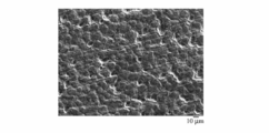
- FIG. 2 is a photograph showing a surface form of a side surface of a piston ring of Example 1 after an engine test.
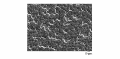
- 3 is a photograph showing a surface form of a side surface of a piston ring of Comparative Example 1 after an engine test.
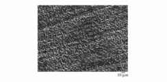
- 6 is a photograph showing a surface form of a side surface of a piston ring of Comparative Example 2 after an engine test.
- 6 is a photograph showing a surface form of a side surface of a piston ring of Example 5 after an engine test.
- 6 is a photograph showing a surface form of a side surface of a piston ring of Comparative Example 4 after an engine test. It is a figure which shows the operation
- the piston ring of the present invention is a steel piston ring in which a nitride layer is formed on at least one of the upper and lower side surfaces, and the nitride layer includes at least one of a granular and worm-like surface form.
- the granular and / or worm-like surface morphology having a predetermined size is related to the local elution of Fe by the etching reaction from the nitrided diffusion layer in the phosphate conversion treatment, and the nucleation and crystal growth of phosphate crystals, As a result, it is formed depending on the morphology and size of the phosphate crystals formed on the surface.
- the crystal form can take various forms such as needles, leaves, columns, plates, grains, etc., but the nitriding diffusion layer of the base material directly under the phosphate conversion coating
- the surface morphology is a granular and / or worm-like surface morphology.
- FIGS. 1 to 5 are photographs showing the surface morphology of the side surface of the piston ring after an engine test of an example and a comparative example which will be described later.
- FIG. 2 shows a relatively smooth surface in the form of the surface of the side surface of the piston ring, which is a nitride layer alone and not subjected to phosphate conversion treatment.
- FIG. 1 and FIGS. 3 to 5 show the surface form of the side surface of the piston ring subjected to the phosphate conversion treatment, and the state where the originally existing phosphate crystal film was worn and disappeared in the initial stage of the engine test.
- the nitrided diffusion layer itself includes a granular and / or worm-like surface morphology.
- FIG. 3 although the nitriding treatment is not performed, a surface form similar to that in FIG. 1 is obtained by performing the phosphate chemical conversion treatment.
- FIGS. 4 and 5 show the grain and / or worm-like surface morphology of FIG. 1 or FIG. 3 made finer.
- the worm-like surface morphology can be considered to be connected to the granular surface morphology.
- the minor axis of the worm-like surface morphology corresponds to the particle size of the granular surface morphology.
- the particle diameter of the granular surface form and the average diameter of the minor axis of the worm-like surface form are preferably in the range of 3 to 40 ⁇ m. More preferably, it is in the range of 5 to 35 ⁇ m, and still more preferably in the range of 10 to 35 ⁇ m.
- the degree of unevenness of the granular and / or worm-like surface morphology is preferably 2.5 to 6 ⁇ m in terms of the maximum height Rz of JIS B0601-2001 when evaluated by the parameters of the surface roughness curve.
- Rz is more preferably 2.5 to 5.5 ⁇ m, and further preferably 2.5 to 5.0 ⁇ m.
- the piston ring of the present invention is characterized by the surface form of the nitride layer on the side surface.
- the phosphate chemical conversion film formed by chemical conversion treatment which is a means for forming the surface form, When used, it preferably rests on the nitride layer.
- the phosphate chemical conversion film functions as a conforming layer, and the presence of the phosphate chemical conversion film ensures the initial side airtightness.
- the phosphate chemical conversion treatment used for piston rings includes zinc phosphate, zinc phosphate, manganese phosphate and the like.
- the phosphate chemical conversion coating of the present invention is preferably a calcium phosphate coating.
- the piston ring of the present invention is preferably implemented using low alloy steel from the economical aspect.
- the base material of the piston ring of the present invention is made of steel containing C, Si, Mn, Cr as essential alloy elements and Mo, V, B as selective alloy elements, and the composition of the essential alloy elements is mass%.
- This steel material is a steel material proposed by the present inventor in Japanese Patent Application No. 2014-10493, and the compositional sum of the alloy elements is limited to less than 3.0% by mass%, so that excellent workability and heat conduction are excellent. Piston ring can be used. Moreover, in addition to reducing Si in the matrix, C is precipitated as a carbide by heat treatment, and C in the remaining grains is segregated to the grain boundaries (former austenite grain boundaries), Improves the diffusion coefficient of nitrogen (N). As a result, the depth of the nitrided diffusion layer having a predetermined hardness is increased in spite of being a low alloy steel, and a nitrided layer having excellent wear resistance can be obtained.
- C precipitates as a carbide by heat treatment
- C when C precipitates as a carbide by heat treatment, C as a solute in the base material decreases, and when C concentrates at a crystal grain boundary (austenite crystal grain boundary), less C dissolves in the crystal grain.
- annealing is preferably performed at a temperature of 600 to 720 ° C. below the Ac1 point of the Fe—C phase diagram for 30 to 240 minutes. This annealing is preferably performed in a wire drawing / heat treatment process (including patenting treatment and oil tempering treatment) of the wire after hot rolling of the steel material.
- the oil temper treatment needs to be set to a temperature and time so that all the carbides do not dissolve, and the quenching process is performed at a temperature of 820 to 980 ° C. for several tens of seconds to several minutes (for example, 30 seconds to 3 minutes), and the tempering step is preferably performed at a temperature of 440 to 500 ° C. for several tens of seconds to several minutes (for example, 30 seconds to 3 minutes).
- the strain relief heat treatment is performed to avoid deformation due to the strain introduced by the piston ring forming process. During this heat treatment, C concentrates at the crystal grain boundaries and, like B, the grain boundary agglomerates.
- the strain relief heat treatment is preferably performed at a high heat treatment temperature as long as the hardness of the base material is not greatly softened. Specifically, it is preferably performed at 420 to 480 ° C.
- C fixed as carbide is released by absorbing N during subsequent nitridation (changing from carbonitride to nitride), and the released C atoms are concentrated and aggregated at the grain boundaries. Therefore, after nitriding, C at the grain boundaries becomes more obvious.
- the compound layer is removed so that the outermost surface of the nitrided layer is composed of a diffusion layer.
- the outermost surface of the nitride layer defined in the present invention means the interface between the nitride layer and the phosphate chemical conversion film.
- the diffusion layer has a Vickers hardness of 700 HV0.05 or more.
- the diffusion layer of 700 to 900 mm HV0.05 is 30 ⁇ m or more. More preferably, it is 40 ⁇ m or more, and further preferably 50 ⁇ m or more.
- the nitride layer is preferably homogeneous in the depth direction, and from the outermost surface to a depth of 30 ⁇ m, the hardness reduction rate in the depth direction is preferably 3 HV0.05 / ⁇ m or less. It is more preferably 2 HV0.05 / ⁇ m or less, and further preferably 1 HV0.05 / ⁇ m or less. In order to make the hardness reduction rate in the depth direction as small as possible, it is necessary to increase the diffusion coefficient of nitrogen in the crystal grains.
- the base material needs to have a predetermined hardness (for example, 400 to 500 mm HV1), but the allowable degree of softening is 90 to 100 of the base material hardness before the nitriding treatment. % Is preferred. More preferably, it is 92 to 100%, and further preferably 94 to 100%.
- the nitriding treatment is preferably performed at a temperature within ⁇ 30 ° C. of the tempering temperature.
- the nitride layer is formed on at least one of the upper and lower side surfaces.
- it may be formed on the entire surface of the piston ring, but the outer peripheral sliding surface may be formed on the nitrided layer or without the nitrided layer by forming a hard film according to the application such as CrN, TiN, DLC, etc. it can.
- the method for producing a piston ring according to the present invention is characterized in that after forming a piston ring from a steel wire, at least one of upper and lower side surfaces is subjected to nitriding treatment and further subjected to phosphate chemical conversion treatment.
- the nitriding treatment is not limited to gas nitriding but can be formed by salt bath nitriding or plasma nitriding. From the viewpoint of avoiding the formation of the outermost compound layer, plasma nitriding can be preferably used. If the compound layer is present on the outermost surface of the piston ring side surface subjected to nitriding treatment, the compound layer is removed, and after fine adjustment of dimensions, parallelism, and surface roughness, phosphate chemical conversion treatment is performed.
- any of zinc phosphate treatment, zinc calcium phosphate treatment, and manganese phosphate treatment can be applied, but the nitride layer formed on the piston ring of the present invention has a predetermined size of granular and / or In order to have a worm-like surface morphology, zinc calcium phosphate treatment is preferred.
- the treatment temperature is 75 to 95 ° C. and the total acidity is 30 to 55 points.
- Example 1 and Comparative Examples 1-2 10 kg vacuum induction melting furnace with steel material whose material composition is mass%, C: 0.52%, Si: 0.27%, Mn: 0.81%, Cr: 0.95%, V: 0.18%, the balance being Fe and inevitable impurities It melted using.
- a wire material having a diameter of 10 mm ⁇ was formed through hot working, and further drawn to prepare a wire material having a thickness of 2.3 mm and a width of 1.0 mm and a rectangular cross-sectional shape.
- an annealing process at 700 ° C. for 60 minutes was sandwiched in the course of the wire drawing process.
- the oil temper treatment was a treatment comprising heating from 930 ° C. for 45 seconds to oil quenching to 60 ° C.
- 150 pressure rings having a nominal diameter of 73 mm ⁇ were formed from the above wire, and subjected to strain relief heat treatment at 450 ° C. for 60 minutes. Furthermore, a CrN film by ion plating was formed on the outer peripheral surface.
- nitride layers by gas nitriding were formed on the upper and lower side surfaces and the inner peripheral surface.
- the nitriding conditions were 500 ° C. and 180 minutes, and the hardness of the base material before nitriding was measured.
- the compound layer on the outermost surface of the nitride layer was removed by grinding.
- a zinc calcium phosphate-based chemical conversion treatment was performed at a treatment temperature of 85 ° C. and a treatment time of 5 hours. The test was carried out under the condition of a total acidity of 35 points, and a zinc calcium phosphate film was coated on both the upper and lower side surfaces and the inner peripheral surface.
- Fatigue strength is defined as “maximum stress that does not break up to 10 7 repetitions in the SN diagram” and is the sum of stress (f 2 ) and load stress when closed to the nominal diameter.
- the pressure rings of Example 1 and Comparative Examples 1 and 2 had f 2 of 307 MPa, and the fatigue strength was 980 MPa in Example 1, 985 MPa in Comparative Example 1, and 730 MPa in Comparative Example 2. That is, the pressure ring (Example 1) with the phosphate conversion treatment on the nitride layer has the same fatigue strength as the pressure ring without the conversion treatment (Comparative Example 1). It was found that the fatigue strength of the pressure ring (Comparative Example 2) that was subjected to the phosphate conversion treatment without forming was reduced by about 25%.
- Example 1 The pressure ring of Example 1 is used as a top ring, and a 1.5-liter four-cylinder gasoline engine is used.
- a pressure ring of Comparative Example 2 was attached to the pressure ring and the fourth cylinder, and an engine test was conducted for 300 hours under predetermined operating conditions.
- As the second ring and the oil ring an existing ring for the engine was used.
- Example 1 As a result of measuring the amount of wear on the lower surface of the top ring, Example 1 averaged 1.7 ⁇ m, Comparative Example 1 was 14 ⁇ m, and Comparative Example 2 was 1.0 ⁇ m.
- the phosphate conversion treatment was not performed even if a nitride layer was present on the side surface of the top ring, the wear resistance was remarkably reduced. When treated, it showed excellent wear resistance.
- Example 1 to 3 show the bottom surface of the top ring observed with a scanning electron microscope (SEM) after completion of the engine test.
- SEM scanning electron microscope
- Example 1 and Comparative Example 2 the particle size of the granular surface morphology and the minor axis of the worm-like surface morphology were measured and averaged to be 18 ⁇ m in Example 1 and 20 ⁇ m in Comparative Example 2.
- the maximum height Rz of the surface roughness curve was 3.4 ⁇ m in Example 1 and 4.8 ⁇ m in Comparative Example 2.
- Examples 2 to 3 and Comparative Example 3 Examples 2 to 3 (total acidity is 40 points and 50 points, respectively) in the same manner as in Example 1 except that the chemical conversion treatment of zinc calcium phosphate was changed between 40 and 60 points. ) And Comparative Example 3 (total acidity 60 points).
- Examples 4 to 5 and Comparative Example 4 Examples 4 to 5 (total acidity of 35 points and 20 points, respectively), except that the chemical conversion treatment was changed to manganese phosphate and the total acidity was changed between 5 and 35 points. ) And Comparative Example 4 (total acidity is 10 points).
- Example 6 Material composition is mass%, C: 0.60%, Si: 1.35%, Mn: 0.70%, Cr: 0.73%, the balance is Fe and unavoidable impurities, 2.3 mm thick, 1.0 mm wide A pressure ring of Example 6 was manufactured in the same manner as in Example 1 except that a wire having a rectangular cross section was used.
- Example 7 The material composition consists of steel materials with mass%, C: 0.60%, Si: 1.90%, Mn: 0.70%, Cr: 0.85%, V: 0.10, Ni: 0.21%, the balance being Fe and inevitable impurities, A pressure ring of Example 7 was manufactured in the same manner as Example 1 except that a wire rod having a thickness of 2.3 mm and a width of 1.0 mm having a rectangular cross-sectional shape was used.
- Example 2 to 7 and Comparative Examples 3 to 4 engine tests were performed under the same conditions as in Example 1 using the same engine used in Example 1.
- An engine test in which the pressure rings of Examples 2 to 5 were attached to each cylinder and an engine test in which the pressure rings of Examples 6 to 7 and Comparative Examples 3 to 4 were attached to each cylinder were conducted.
- the amount of wear on the lower surface of each pressure ring, the average diameter of the granular and / or worm-like surface morphology, and the maximum height Rz of the surface roughness curve were measured.
- Table 2 including the results of Example 1 and Comparative Examples 1 and 2.
- the fatigue strength will be reduced, so it is not included in the scope of the present invention. It is considered that the fatigue strength did not decrease because the piston ring having the nitride layer introduced residual compressive stress on the surface.
- Example 4 and 5 show scanning electron microscope (SEM) photographs of the lower surface of the top ring after completion of the engine test for Example 5 and Comparative Example 4 subjected to manganese phosphate conversion treatment. It can be seen that the size of the particulate and worm-like surface morphology is considerably refined as compared with the zinc phosphate-based chemical conversion treatment. Taking these sizes into consideration, the phosphate chemical conversion treatment is preferably a zinc calcium phosphate system.
- Examples 6 and 7 were predicted to be slightly inferior in nitriding characteristics because Si was a steel material in the order of 1% by mass, but the resistance to resistance sufficiently improved by the presence of the granular and / or worm-like surface morphology of the present invention. Abrasion was shown.
Landscapes
- Chemical & Material Sciences (AREA)
- Engineering & Computer Science (AREA)
- Mechanical Engineering (AREA)
- Chemical Kinetics & Catalysis (AREA)
- Materials Engineering (AREA)
- Metallurgy (AREA)
- Organic Chemistry (AREA)
- General Engineering & Computer Science (AREA)
- Combustion & Propulsion (AREA)
- General Chemical & Material Sciences (AREA)
- Inorganic Chemistry (AREA)
- Pistons, Piston Rings, And Cylinders (AREA)
Abstract
La présente invention vis à procurer : un segment de piston grâce auquel l'adhérence de l'aluminium peut être évitée pendant de longues périodes, même quand il est utilisé dans un environnement à température élevée et à pression élevée, et qui présente une excellente résistance à l'abrasion de surfaces latérales ; et un procédé de fabrication pour ce dernier. Selon l'invention, par la formation d'une couche de nitrure sur la surface latérale supérieure et/ou inférieure du segment de piston, puis par l'application d'un traitement de conversion chimique au phosphate, la couche de nitrure est constituée de façon à comprendre des formes de surface granuleuses et/ou vermiformes.
Priority Applications (3)
| Application Number | Priority Date | Filing Date | Title |
|---|---|---|---|
| CN201680030704.0A CN107636367B (zh) | 2015-07-17 | 2016-07-14 | 活塞环及其制造方法 |
| EP16827699.6A EP3327320A4 (fr) | 2015-07-17 | 2016-07-14 | Segment de piston et procédé de fabrication pour ce dernier |
| US15/744,609 US10502319B2 (en) | 2015-07-17 | 2016-07-14 | Piston ring and its production method |
Applications Claiming Priority (2)
| Application Number | Priority Date | Filing Date | Title |
|---|---|---|---|
| JP2015-142692 | 2015-07-17 | ||
| JP2015142692A JP6139605B2 (ja) | 2015-07-17 | 2015-07-17 | ピストンリング及びその製造方法 |
Publications (1)
| Publication Number | Publication Date |
|---|---|
| WO2017014139A1 true WO2017014139A1 (fr) | 2017-01-26 |
Family
ID=57833955
Family Applications (1)
| Application Number | Title | Priority Date | Filing Date |
|---|---|---|---|
| PCT/JP2016/070809 Ceased WO2017014139A1 (fr) | 2015-07-17 | 2016-07-14 | Segment de piston et procédé de fabrication pour ce dernier |
Country Status (5)
| Country | Link |
|---|---|
| US (1) | US10502319B2 (fr) |
| EP (1) | EP3327320A4 (fr) |
| JP (1) | JP6139605B2 (fr) |
| CN (1) | CN107636367B (fr) |
| WO (1) | WO2017014139A1 (fr) |
Families Citing this family (7)
| Publication number | Priority date | Publication date | Assignee | Title |
|---|---|---|---|---|
| CN109372651B (zh) * | 2018-09-25 | 2021-06-08 | 安庆帝伯格茨活塞环有限公司 | 一种类金刚石涂层活塞环及制备方法 |
| CN110625206A (zh) * | 2019-09-30 | 2019-12-31 | 江苏大学 | 一种活塞环表面微型储油腔加工方法 |
| DE102020202259A1 (de) * | 2020-02-21 | 2021-08-26 | Federal-Mogul Burscheid Gmbh | Gleitelement, insbesondere Kolbenring, und Verfahren zur Herstellung desselben |
| CN115306580B (zh) * | 2022-08-29 | 2024-03-01 | 奇瑞汽车股份有限公司 | 一种提升发动机油环刮片质量的方法 |
| CA223481S (en) * | 2023-01-12 | 2025-04-25 | Procter & Gamble | Packaging with ornamentation |
| JP7467783B1 (ja) | 2024-02-05 | 2024-04-15 | トクセン工業株式会社 | 圧力リング用線 |
| JP7508717B1 (ja) | 2024-02-05 | 2024-07-01 | トクセン工業株式会社 | 圧力リング用線 |
Citations (4)
| Publication number | Priority date | Publication date | Assignee | Title |
|---|---|---|---|---|
| JPH10339370A (ja) * | 1997-05-17 | 1998-12-22 | Ae Goetze Gmbh | 鋳鉄製ピストンリング |
| JP2000002333A (ja) * | 1998-06-18 | 2000-01-07 | Teikoku Piston Ring Co Ltd | ピストンリング |
| JP2000144376A (ja) * | 1998-11-18 | 2000-05-26 | Sumitomo Electric Ind Ltd | 摺動特性の良好な皮膜 |
| JP2008241032A (ja) * | 2007-02-28 | 2008-10-09 | Nippon Piston Ring Co Ltd | ピストンリング及びその製造方法 |
Family Cites Families (16)
| Publication number | Priority date | Publication date | Assignee | Title |
|---|---|---|---|---|
| JPS6082552U (ja) | 1983-11-14 | 1985-06-07 | 帝国ピストンリング株式会社 | ピストンリング |
| EP0295111B1 (fr) * | 1987-06-11 | 1994-11-02 | Aichi Steel Works, Ltd. | Acier présentant une résistance élevée à l'usure |
| JPH01307568A (ja) | 1988-06-06 | 1989-12-12 | Nippon Piston Ring Co Ltd | ピストンリング |
| JPH0578856A (ja) * | 1991-09-25 | 1993-03-30 | Mazda Motor Corp | 金属の被膜成形方法および被膜が形成された金属体 |
| JP4724275B2 (ja) * | 2000-07-17 | 2011-07-13 | 株式会社リケン | 耐スカッフィング性、耐クラッキング性及び耐疲労性に優れたピストンリング及びその製造方法 |
| CN1330873C (zh) | 2002-07-25 | 2007-08-08 | 株式会社理研 | 活塞环 |
| JP2004068815A (ja) | 2002-07-25 | 2004-03-04 | Riken Corp | ピストンリング |
| DE102004028487B4 (de) * | 2004-06-11 | 2018-11-15 | Mahle Gmbh | Verfahren zur Herstellung verschleissfester Flanken für einen Trapezring für Verbrennungsmotoren |
| JP2007162574A (ja) | 2005-12-14 | 2007-06-28 | Riken Corp | ピストンリング |
| JPWO2009069703A1 (ja) * | 2007-11-30 | 2011-04-14 | 日本ピストンリング株式会社 | 内燃機関のピストンリングとシリンダライナとの組合せ構造 |
| JP5828575B2 (ja) * | 2008-03-04 | 2015-12-09 | 日産自動車株式会社 | ピストンリング |
| BRPI0905228B1 (pt) | 2009-12-29 | 2017-01-24 | Mahle Metal Leve Sa | anel de pistão nitretado resistente à propagação de trincas |
| JP5676146B2 (ja) * | 2010-05-25 | 2015-02-25 | 株式会社リケン | 圧力リング及びその製造方法 |
| JP5885190B2 (ja) * | 2010-12-28 | 2016-03-15 | 日本ピストンリング株式会社 | ピストンリング及びピストンリングの製造方法 |
| JP6454103B2 (ja) * | 2013-08-12 | 2019-01-16 | 株式会社リケン | 圧力リング |
| JP6313601B2 (ja) * | 2014-01-23 | 2018-04-18 | 株式会社リケン | ピストンリング及びその製造方法 |
-
2015
- 2015-07-17 JP JP2015142692A patent/JP6139605B2/ja not_active Expired - Fee Related
-
2016
- 2016-07-14 WO PCT/JP2016/070809 patent/WO2017014139A1/fr not_active Ceased
- 2016-07-14 US US15/744,609 patent/US10502319B2/en active Active
- 2016-07-14 EP EP16827699.6A patent/EP3327320A4/fr not_active Withdrawn
- 2016-07-14 CN CN201680030704.0A patent/CN107636367B/zh active Active
Patent Citations (4)
| Publication number | Priority date | Publication date | Assignee | Title |
|---|---|---|---|---|
| JPH10339370A (ja) * | 1997-05-17 | 1998-12-22 | Ae Goetze Gmbh | 鋳鉄製ピストンリング |
| JP2000002333A (ja) * | 1998-06-18 | 2000-01-07 | Teikoku Piston Ring Co Ltd | ピストンリング |
| JP2000144376A (ja) * | 1998-11-18 | 2000-05-26 | Sumitomo Electric Ind Ltd | 摺動特性の良好な皮膜 |
| JP2008241032A (ja) * | 2007-02-28 | 2008-10-09 | Nippon Piston Ring Co Ltd | ピストンリング及びその製造方法 |
Non-Patent Citations (1)
| Title |
|---|
| See also references of EP3327320A4 * |
Also Published As
| Publication number | Publication date |
|---|---|
| JP2017025963A (ja) | 2017-02-02 |
| CN107636367A (zh) | 2018-01-26 |
| CN107636367B (zh) | 2020-03-13 |
| EP3327320A4 (fr) | 2019-04-10 |
| EP3327320A1 (fr) | 2018-05-30 |
| US20180209541A1 (en) | 2018-07-26 |
| US10502319B2 (en) | 2019-12-10 |
| JP6139605B2 (ja) | 2017-05-31 |
Similar Documents
| Publication | Publication Date | Title |
|---|---|---|
| JP6139605B2 (ja) | ピストンリング及びその製造方法 | |
| JP5030439B2 (ja) | 摺動部材 | |
| JP5676146B2 (ja) | 圧力リング及びその製造方法 | |
| JP2001098343A (ja) | 耐高面圧部材およびその製造方法 | |
| CN105579749A (zh) | 压力环 | |
| MX2011009958A (es) | Tira de acero al niquel con muy bajo contenido en carbono. | |
| JP5762843B2 (ja) | 圧力リング及びその製造方法 | |
| CN107429356B (zh) | 滑动构造体 | |
| US12365959B2 (en) | Oil ring wire | |
| JP6410613B2 (ja) | 耐焼付性に優れた浸炭部材 | |
| JP6454103B2 (ja) | 圧力リング | |
| JP5763260B2 (ja) | 圧力リング用線材及びその製造方法 | |
| JP5060083B2 (ja) | ピストンリングの製造方法 | |
| JP6313601B2 (ja) | ピストンリング及びその製造方法 | |
| CN112055794B (zh) | 活塞环 | |
| TWI800200B (zh) | 油環用線 | |
| JP6587570B2 (ja) | 内燃機関用ピストンリング線材及び内燃機関用ピストンリング | |
| JP2002348639A (ja) | イオンプレーティング処理に適した疲労強度,耐熱へたり性に優れたピストンリング用鋼 |
Legal Events
| Date | Code | Title | Description |
|---|---|---|---|
| 121 | Ep: the epo has been informed by wipo that ep was designated in this application |
Ref document number: 16827699 Country of ref document: EP Kind code of ref document: A1 |
|
| WWE | Wipo information: entry into national phase |
Ref document number: 15744609 Country of ref document: US |
|
| NENP | Non-entry into the national phase |
Ref country code: DE |
|
| WWE | Wipo information: entry into national phase |
Ref document number: 2016827699 Country of ref document: EP |