WO2017014164A1 - Système de communication, dispositif de communication, procédé de communication, terminal, et programme - Google Patents
Système de communication, dispositif de communication, procédé de communication, terminal, et programme Download PDFInfo
- Publication number
- WO2017014164A1 WO2017014164A1 PCT/JP2016/070907 JP2016070907W WO2017014164A1 WO 2017014164 A1 WO2017014164 A1 WO 2017014164A1 JP 2016070907 W JP2016070907 W JP 2016070907W WO 2017014164 A1 WO2017014164 A1 WO 2017014164A1
- Authority
- WO
- WIPO (PCT)
- Prior art keywords
- terminal
- area network
- wide area
- gateway
- data center
- Prior art date
- Legal status (The legal status is an assumption and is not a legal conclusion. Google has not performed a legal analysis and makes no representation as to the accuracy of the status listed.)
- Ceased
Links
Images



Classifications
-
- H—ELECTRICITY
- H04—ELECTRIC COMMUNICATION TECHNIQUE
- H04L—TRANSMISSION OF DIGITAL INFORMATION, e.g. TELEGRAPHIC COMMUNICATION
- H04L12/00—Data switching networks
- H04L12/28—Data switching networks characterised by path configuration, e.g. LAN [Local Area Networks] or WAN [Wide Area Networks]
- H04L12/46—Interconnection of networks
- H04L12/4641—Virtual LANs, VLANs, e.g. virtual private networks [VPN]
-
- H—ELECTRICITY
- H04—ELECTRIC COMMUNICATION TECHNIQUE
- H04L—TRANSMISSION OF DIGITAL INFORMATION, e.g. TELEGRAPHIC COMMUNICATION
- H04L12/00—Data switching networks
- H04L12/28—Data switching networks characterised by path configuration, e.g. LAN [Local Area Networks] or WAN [Wide Area Networks]
- H04L12/46—Interconnection of networks
- H04L12/4633—Interconnection of networks using encapsulation techniques, e.g. tunneling
-
- H—ELECTRICITY
- H04—ELECTRIC COMMUNICATION TECHNIQUE
- H04L—TRANSMISSION OF DIGITAL INFORMATION, e.g. TELEGRAPHIC COMMUNICATION
- H04L45/00—Routing or path finding of packets in data switching networks
- H04L45/64—Routing or path finding of packets in data switching networks using an overlay routing layer
-
- H—ELECTRICITY
- H04—ELECTRIC COMMUNICATION TECHNIQUE
- H04L—TRANSMISSION OF DIGITAL INFORMATION, e.g. TELEGRAPHIC COMMUNICATION
- H04L63/00—Network architectures or network communication protocols for network security
- H04L63/04—Network architectures or network communication protocols for network security for providing a confidential data exchange among entities communicating through data packet networks
- H04L63/0428—Network architectures or network communication protocols for network security for providing a confidential data exchange among entities communicating through data packet networks wherein the data content is protected, e.g. by encrypting or encapsulating the payload
- H04L63/0485—Networking architectures for enhanced packet encryption processing, e.g. offloading of IPsec packet processing or efficient security association look-up
-
- H—ELECTRICITY
- H04—ELECTRIC COMMUNICATION TECHNIQUE
- H04L—TRANSMISSION OF DIGITAL INFORMATION, e.g. TELEGRAPHIC COMMUNICATION
- H04L63/00—Network architectures or network communication protocols for network security
- H04L63/08—Network architectures or network communication protocols for network security for authentication of entities
- H04L63/0876—Network architectures or network communication protocols for network security for authentication of entities based on the identity of the terminal or configuration, e.g. MAC address, hardware or software configuration or device fingerprint
-
- H—ELECTRICITY
- H04—ELECTRIC COMMUNICATION TECHNIQUE
- H04L—TRANSMISSION OF DIGITAL INFORMATION, e.g. TELEGRAPHIC COMMUNICATION
- H04L63/00—Network architectures or network communication protocols for network security
- H04L63/08—Network architectures or network communication protocols for network security for authentication of entities
- H04L63/0892—Network architectures or network communication protocols for network security for authentication of entities by using authentication-authorization-accounting [AAA] servers or protocols
-
- H—ELECTRICITY
- H04—ELECTRIC COMMUNICATION TECHNIQUE
- H04W—WIRELESS COMMUNICATION NETWORKS
- H04W12/00—Security arrangements; Authentication; Protecting privacy or anonymity
- H04W12/03—Protecting confidentiality, e.g. by encryption
-
- H—ELECTRICITY
- H04—ELECTRIC COMMUNICATION TECHNIQUE
- H04L—TRANSMISSION OF DIGITAL INFORMATION, e.g. TELEGRAPHIC COMMUNICATION
- H04L12/00—Data switching networks
- H04L12/66—Arrangements for connecting between networks having differing types of switching systems, e.g. gateways
-
- H—ELECTRICITY
- H04—ELECTRIC COMMUNICATION TECHNIQUE
- H04L—TRANSMISSION OF DIGITAL INFORMATION, e.g. TELEGRAPHIC COMMUNICATION
- H04L63/00—Network architectures or network communication protocols for network security
- H04L63/02—Network architectures or network communication protocols for network security for separating internal from external traffic, e.g. firewalls
- H04L63/0227—Filtering policies
-
- H—ELECTRICITY
- H04—ELECTRIC COMMUNICATION TECHNIQUE
- H04L—TRANSMISSION OF DIGITAL INFORMATION, e.g. TELEGRAPHIC COMMUNICATION
- H04L63/00—Network architectures or network communication protocols for network security
- H04L63/02—Network architectures or network communication protocols for network security for separating internal from external traffic, e.g. firewalls
- H04L63/0227—Filtering policies
- H04L63/0245—Filtering by information in the payload
-
- H—ELECTRICITY
- H04—ELECTRIC COMMUNICATION TECHNIQUE
- H04L—TRANSMISSION OF DIGITAL INFORMATION, e.g. TELEGRAPHIC COMMUNICATION
- H04L63/00—Network architectures or network communication protocols for network security
- H04L63/16—Implementing security features at a particular protocol layer
- H04L63/164—Implementing security features at a particular protocol layer at the network layer
-
- H—ELECTRICITY
- H04—ELECTRIC COMMUNICATION TECHNIQUE
- H04W—WIRELESS COMMUNICATION NETWORKS
- H04W12/00—Security arrangements; Authentication; Protecting privacy or anonymity
- H04W12/009—Security arrangements; Authentication; Protecting privacy or anonymity specially adapted for networks, e.g. wireless sensor networks, ad-hoc networks, RFID networks or cloud networks
-
- H—ELECTRICITY
- H04—ELECTRIC COMMUNICATION TECHNIQUE
- H04W—WIRELESS COMMUNICATION NETWORKS
- H04W12/00—Security arrangements; Authentication; Protecting privacy or anonymity
- H04W12/08—Access security
- H04W12/088—Access security using filters or firewalls
-
- H—ELECTRICITY
- H04—ELECTRIC COMMUNICATION TECHNIQUE
- H04W—WIRELESS COMMUNICATION NETWORKS
- H04W84/00—Network topologies
- H04W84/02—Hierarchically pre-organised networks, e.g. paging networks, cellular networks, WLAN [Wireless Local Area Network] or WLL [Wireless Local Loop]
- H04W84/10—Small scale networks; Flat hierarchical networks
- H04W84/12—WLAN [Wireless Local Area Networks]
Definitions
- the present invention is based on the priority claim of Japanese patent application: Japanese Patent Application No. 2015-143405 (filed on July 17, 2015), the entire contents of which are incorporated herein by reference. Shall.
- the present invention relates to a communication system, apparatus, method, terminal, and program.
- Evolved Packet System Evolved Packet System: EPS
- EPS Evolved Packet System
- 3GPP access networks include UTRAN (Universal Mobile Telecommunications System (UMTS) Terrestrial Radio Access Network), E-UTRAN (Evolved UTRAN), GERAN (Global System for Mobile Communications (EDSM) EDGE Radio Access Network), and the like.
- UTRAN Universal Mobile Telecommunications System (UMTS) Terrestrial Radio Access Network
- E-UTRAN Evolved UTRAN
- GERAN Global System for Mobile Communications (EDSM) EDGE Radio Access Network
- a non-3GPP access network is an IP (Internet Protocol) access network that uses access technologies with specifications outside the range of 3GPP.
- Wi-Fi is defined in the IEEE (The Institute of Electrical and Electronics Electronics, Engineers, 802.11) specifications. (Registered Trademark: “Wireless Fidelity”) and WiMAX (Wireless Local Area Network: WLAN) such as WiMAX (Worldwide Interoperability for Microwave Access) defined by IEEE802.16 specification are included.
- WiMAX Wireless Local Area Network
- IEEE802.16 IEEE802.16 specification are included.
- 3GPP TS23.402 Architecture enhancements for non-3GPP accesses may be referred to.
- Wi-Fi (registered trademark) -Calling is a service provided by a communication carrier.
- This service is a service (User Equipment: UE) in which a SIM (Subscriber Identity Module) of the communication carrier is inserted.
- Voice calls and short message services can be used via a registered trademark (see Non-Patent Document 1).
- the terminal connects to the security gateway of the communication carrier via Wi-Fi (registered trademark) using UMA (Unlicensed Mobile Access) technology and is authenticated by SIM authentication, it connects to the switch on the core network of the communication carrier and the other party (It may be a fixed telephone, a subscriber terminal of another communication carrier, etc.).
- Wi-Fi registered trademark
- Wi-Fi registered trademark
- FIG. 1 is a diagram for explaining EPS including a non-3GPP access network.
- a terminal (UE) 1 such as a smartphone is connected to a packet data network (Packet Data Network: PDN) 30 through a base station (evolved Node B: eNB) 10 and an evolved packet core (Evolved Packet Core: EPC) 20
- PDN Packet Data Network
- eNB evolved Node B
- EPC evolved packet core
- the MME (Mobility Management Entity) 23 of the EPC 20 performs various processes such as mobility management and authentication of the terminal 1 and setting of a user data transfer path. Further, the MME 23 performs user authentication in cooperation with an HSS (Home Subscriber Server: holding a subscriber profile) 24.
- the MME 23 sets and releases the user data transfer path in the section (S1-U) from the SGW (Serving Gateway) 21 to the base station 10.
- the SGW 21 transmits / receives user data to / from the base station 10 and sets / releases a communication path to / from the PGW (PacketPackData Network gateway) 22.
- the PGW 22 is connected to a packet data network (PDN) 30 such as an IMS (IP Multimedia Subsystem) or the Internet.
- PDN packet data network
- the PGW 22 assigns an IP address (private IP address) to the terminal 1 and the like.
- a PCRF (Policy and Charging Rules function) 26 determines policy control and charging control rules such as QoS (Quality of Service). Based on the notification information from the PCRF 26, the PGW 22 and the SGW 21 perform policy control for each packet, for example.
- reference numerals S11 and the like of the lines between the nodes represent interfaces, a broken line represents a control plane (C-Plane), and a solid line represents a user plane (U-Plane) signal (data).
- C-Plane control plane
- U-Plane user plane
- 3GPP TS 23.401 GPRS Enhancements for E-UTRAN Access may be referred to.
- a call request from the terminal 1 is sent to the PGW 22 via the wireless LAN access point 41 and Un-Trusted Access (untrusted access) via the ePDG (evolved Packet Data Data Gateway) 27.
- the PDN 30 for example, IMS service.
- EPDG27 is an IPsec gateway that terminates IPsec (Security Architecture for Internet Protocol) connection from the mobile interface (SWu).
- IPsec Security Architecture for Internet Protocol
- the terminal 1 detects the ePDG 27 and exchanges a key with the ePDG 27 (IKEv2), Then, an IPsec tunnel is established, and a PDN (Packet Data Network) connection is established with the PGW 22 through the established IPsec tunnel.
- IKEv2 a key with the ePDG 27
- PDN Packet Data Network
- the ePDG 27 relays an EAP (Extensible Authentication Authentication Protocol) message from the terminal 1 to the 3GPP AAA (Authentication Authorization Accounting) server 25.
- the 3GPP AAA server 25 performs EAP-SIM (Extensible Authentication Protocol-Subscriber Identity Module) authentication or EAP -AKA (Extensible Authentication-Protocol-Authentication and Key Agreement) is performed (for example, 3GPP TS 33.402: Security aspects of non-3GPP accesses may be referred to).
- EAP-SIM Extensible Authentication Protocol-Subscriber Identity Module
- EAP -AKA Extensible Authentication-Protocol-Authentication and Key Agreement
- the ePDG 27 sets a tunnel (Proxy Mobile IP) or GTP (GPRS (General Packet Radio System) Tunneling Protocol) to the PGW 22 in the S2b interface (for example, 3GPP TR TR23.834: STUDY ON GPRS Tunneling Protocol (GTP) based S2b etc.).
- GTP General Packet Radio System Tunneling Protocol
- EPDG 27 can connect to PGW 22 via PMIPv6 when non-3GPP access is compatible with PMIPv6 (Proxy Mobile IPv6).
- PMIPv6 Proxy Mobile IPv6
- proxy mobile IP is used between the PGW 22 and the ePDG 27
- the ePDG 27 transmits a proxy binding update (Proxy Binding Update) message to the PGW 22.
- the transmission destination of data to the terminal 1 in the PGW 22 is switched to the ePDG 27.
- PMIPv6 is a mobility control protocol that establishes and releases a tunnel (GRE (Generic Routing Encapsulation) tunnel) for data transfer between a mobility anchor (LMA: Local Mobility Anchor) and a mobility access gateway (MAG: Mobility Access Gateway).
- GRE Generic Routing Encapsulation
- MAG Mobility Access Gateway
- the LMA forwards the packet to the MAG to which the terminal is connected (switches the communication path and forwards the packet addressed to the terminal to the area where it is located).
- a terminal moves from one MAG to another MAG, a data transfer tunnel is established between the LMA that previously established the data transfer tunnel and the MAG to which the terminal is newly connected.
- 3GPP AAA server 25 provides network access authentication, authorization, and accounting services from users. The authorization for non-3GPP access is performed between the terminal 1 and the 3GPP AAA server 25 and HSS 24. For example, when the terminal 1 establishes an IPsec tunnel with the ePDG 27, mutual authentication is performed between the terminal 1 and the network based on EAP-AKA.
- 3GPP AAA server 3GPP TS 29.273: Evolved Packet System (EPS); 3GPP EPS EPS AAA interfaces, etc. may be referred to.
- EPS Evolved Packet System
- 3GPP EPS EPS AAA interfaces etc.
- the terminal 1 shifts to a trusted non-3GPP access (trusted wireless LAN access point 42 in FIG. 1) or first connects, the MIP (Mobile IP) tunnel (S2a, DSMIPv6 (Dual- Connect directly to the PGW 22 via Stack (MIPv6): IETF (RFC) 5555).
- MIP Mobile IP
- ePDG and 3GPP AAA server 3GPP TS 29.273: Evolved Packet System (EPS); 3GPP EPS EPS AAA interfaces, etc. may be referred to.
- Whether the non-3GPP access network is a reliable access network or an untrusted access network is determined by, for example, a communication carrier (operator) of HPLMN (Home Public Land Mobile Mobile Network).
- IPSec is a protocol that performs packet encryption and authentication at the network layer level.
- AH Authentication Header
- VPN Virtual Private Network
- ESP Encapsulating Security Payload
- IPSec communication includes a transport mode (IPsec between hosts in which IPsec is implemented) and a tunnel mode (IPsec between VPN devices such as routers in which IPsec is implemented).
- transport mode IPsec between hosts in which IPsec is implemented
- tunnel mode IPsec between VPN devices such as routers in which IPsec is implemented
- packet layer 4 or higher data is encrypted (see FIG. 11B), and the packet is transferred based on the original IP header (OriginalIPIP (header).
- the original IP header and data part (FIG. 11A) of the packet are encrypted, and a new IP header (New IP header) is added (see FIG. 11C).
- the ESP packet format consists of an ESP header (ESP header), payload, ESP trailer (ESP trailer), and authentication data (ESP authentication data) (see FIGS. 11B and 11C).
- the ESP header (ESP header) is SPI (Security Parameter Index: 32-bit value that uniquely identifies the SA (security association) for the datagram) and sequence number (Sequence Number) (packet sequence number: 32 bits).
- SPI Security Parameter Index
- sequence Number Packet sequence number: 32 bits
- Have The ESP trailer includes padding (padding field for payload length adjustment), pad length (Pad (length) (number of bytes of Padding), and next header (Next Header) (protocol after ESP: TCP / UDP).
- Authentication data (Authentication data) (HMAC (Hash-based Message Authentication Code)) is a variable length field including an integrity check value (Integrity Check Value: ICV) calculated from the authentication data extracted from the ESP packet.
- SA Security Association
- IPsec parameters security information
- SPI Security Parameter Index
- mode protocol
- encryption algorithm key
- authentication algorithm tunnel endpoint IP address
- IKE Internet Key Exchange
- SA Internet Security Association and Key Management Protocol
- ISAKMP Internet Security Association and Key Management Protocol
- SA Security Association
- WAN wide area network
- LAN Local Area Network
- the filtering service provided by the communication carrier to the subscriber is provided, for example, on the packet core network (EPC) of the communication carrier.
- EPC packet core network
- a parental control function for example, blocking harmful sites, restricting apps to be used, restricting phone / email recipients, restricting usage time and talking time
- parental control for example, blocking harmful sites, restricting apps to be used, restricting phone / email recipients, restricting usage time and talking time
- terminals equipped, parents or the like need to take measures as appropriate for restrictions other than the parental control function provided.
- young people may use general terminals other than so-called children's terminals that have a parental control function and the like.
- an object of the present invention is to provide a system and a method that can provide secure communication while providing necessary protection to a terminal connected to a data center via a wide area network (WAN) such as a wireless LAN and the Internet. It is to provide a device and a program.
- WAN wide area network
- a data center in which a first wide area network (Wide Area Network) is interposed between a wireless LAN (Local Area Network) to which a terminal is connected is provided.
- the data center is A first gateway that connects to the terminal via the wireless LAN via a VPN (Virtual Private Network) via the first wide area network;
- a second gateway connected to a second wide area network;
- a virtual network connected to the first gateway and the second gateway;
- a communication system is provided.
- a communication device in which a first wide area network (Wide Area Network) is interposed between a wireless LAN (Local Area Network) to which a terminal is connected, A first gateway that connects to the terminal via the wireless LAN via a VPN (Virtual Private Network) via the first wide area network; A second gateway connected to a second wide area network; A virtual network connected to the first gateway and the second gateway; At least one of a packet provided between the first gateway and the second gateway and input from the first wide area network side and a packet input from the second wide area network side And a functional block that performs the filtering control.
- a first wide area network Wide Area Network
- VPN Virtual Private Network
- a first gateway of a data center in which a first wide area network (Wide Area Network) is interposed between a wireless LAN (Local Area Network) to which the terminal is connected and the terminal.
- VPN Virtual Private Network
- a communication method for filtering at least one of the packets is provided.
- a terminal connected to a data center via a wireless LAN and a first wide area network (WAN1), A VPN device that connects between the data center and the VPN via the wireless LAN and the wide area network, Connected to the second wide area network (WAN2) via the virtual network that is provided in the data center via the VPN and virtualizes at least a part of the functions of the packet core network, Out of incoming calls to the terminal input to the data center from the second wide area network (WAN2) side or data addressed to the terminal, incoming calls or data filtered in the data center are converted into the VPN.
- a terminal having a receiving function is provided.
- a computer disposed in a data center in which a first wide area network (Wide Area Network) is interposed between a wireless LAN (Local Area Network) to which a terminal is connected, Between the terminal and the data center, a process of establishing a VPN (Virtual Private Network) via the wide area network via the wireless LAN; A process that is provided in the data center from the terminal via the VPN, and that connects to a second wide area network via a virtual network that virtualizes at least a part of the components of the core network; There is provided a program for executing a process of filtering at least one of a packet input from the first wide area network side and a packet input from the second wide area network side.
- VPN Virtual Private Network
- a computer included in a terminal connected to a data center via a wireless LAN and a first wide area network includes: Between the data center and the terminal, a process of establishing a VPN via the wide area network via the wireless LAN; A process of connecting to the second wide area network (WAN2) via the virtual network that is provided in the data center via the VPN and virtualizes at least a part of the functions of the packet core network; Out of incoming calls to the terminal input to the data center from the second wide area network (WAN2) side or data addressed to the terminal, incoming calls or data filtered in the data center are converted into the VPN.
- Process to receive via A program for executing is provided.
- a computer-readable recording medium (a storage such as a semiconductor memory or a CD (Compact Disk) / DVD (Digital Versatile Disk)) on which the program is recorded is provided.
- a storage such as a semiconductor memory or a CD (Compact Disk) / DVD (Digital Versatile Disk)
- WAN wide area network
- FIG. 7 is a diagram illustrating an operation of the embodiment of FIG. 6. It is a figure which illustrates other embodiment of the present invention.
- A is an IP packet
- B is a trans mode ESP packet
- C is a tunnel mode ESP packet
- D is UDP encapsulation
- E is a diagram illustrating an L2TP / IPsec packet.
- virtualized EPC Virtualized EPC
- nodes such as SGW, PGW, MME, HSS, and PCRF
- a virtualized EPC is realized on a general-purpose server or the like installed in a data center (Data Center: DC) of a cloud provider that provides a cloud service (or data center service) to clients. be able to.
- DC data center
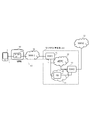
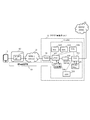
- FIG. 2 is a diagram illustrating an exemplary embodiment of the present invention.
- a virtualized EPC (vEPC) 52 in the data center 50 is obtained by virtualizing at least a part of the EPC 20 of FIG.
- the vEPC 52 may be a virtualized function of some nodes of the EPC 20, such as the ePDG 27, PGW 22, and PCRF 26 of the EPC 20 of FIG.
- the first gateway 51 connects the vEPC 52 with a wide area network (WAN) 1 (31) such as the Internet.
- the second gateway (GW2) 53 connects the WAN 2 (32) such as the Internet or IMS and the vEPC 52.
- a function block (Function Block: FB) 54 that performs packet filtering or data compression or the like. It has.
- the function block (Function Block: FB) 54 can be allocated for each user (terminal 1: subscriber). Although not particularly limited, for example, the service contract information of the terminal 1 acquired by the PCRF (not shown) of the vEPC 52 from SPR (Subscriber Profile Repository) (not shown), the PGW of the vEPC 52 (not shown), etc. Thus, based on the private IP address assigned to the terminal 1, a function block (FB) 54 may be allocated to each terminal 1 with respect to the terminal 1 that has accessed the data center 50.
- the functional block (FB) 54 is a virtual machine (Virtual) that runs on a server connected between the first gateway (GW1) 51 and the second gateway (GW2) 53. Machine).
- the function block (FB) 54 allocated to the terminal 1 (subscriber) is activated based on the subscriber information or service contract information of the terminal 1 by a connection request from the terminal 1 (subscriber).
- the function block (FB) 54 may be terminated in response to the connection termination from the terminal 1 (subscriber).
- the functional block (FB) 54 activated in correspondence with the terminal 1 performs filtering control of packets (downlink) input to the second gateway (GW2) 53 from the WAN2 (32) side. Further, the function block (FB) 54 may be input to the data center 50 from the terminal 1 via the WAN 1 (31) and may perform filtering control of packets (uplink) to the WAN 2 (32) side.
- the functional block (FB) 54 is not limited to the configuration arranged between the first gateway (GW1) 51 and the second gateway (GW2) 53.
- the first gateway (GW1) ) 51 and the second gateway (GW2) 53 may be mounted on a server or the like constituting at least one of them.
- the terminal 1 is connected to the WAN 2 (32) from the WAN 1 (31), the first gateway 51, the vEPC 52, and the second gateway 53 of the data center 50 via the WLAN 40.
- the WLAN 40 may be a home wireless LAN or a public wireless LAN.
- the WLAN 40 includes a wireless LAN access point (WLAN AP) 41 and a wireless LAN router (not shown) equipped with NAT (Network Address Transformation) / NAPT (Network Address Port Translation), etc., via a modem (not shown) or the like.
- WLAN AP wireless LAN access point
- NAT Network Address Transformation
- NAPT Network Address Port Translation
- the connection destination of the terminal 1 is a wireless LAN access point (WLAN AP) 41.
- the terminal 1 switches the connection destination to the 3GPP access network (for example, the eNB 10 in FIG. 1), connects to the WAN 1 (31) and connects to the data center 50 through the packet core network (EPC 20 in FIG. 1).
- the 3GPP access network for example, the eNB 10 in FIG. 1
- the WAN 1 311
- the packet core network EPC 20 in FIG.
- a VPN tunnel is established between the gateway device (GW) (for example, 51) of the data center 50 and the terminal 1.
- a VPN device VPN router
- the terminal 1 is equipped with a VPN device and functions as a VPN client.
- VPN connections include tunneling and encryption.
- WAN1 (31) is the Internet, this VPN is a so-called Internet VPN.
- the data center 50 passes through, for example, the first gateway (GW 1) 51, vEPC 52, and the second gateway (GW 2) 53.
- GW 1 the first gateway
- vEPC 52 the second gateway
- GW 2 the second gateway
- a packet (traffic) for data communication between the terminal 1 and the WAN 2 (32) does not pass through the vEPC 52 in the data center 50, and the first gateway (GW1) 51 and the second gateway (GW2) 53 You may make it off-load to the virtual network 55 in the meantime.
- voice packets may be transferred onto the virtual network 55 between the first gateway (GW1) 51 and the second gateway (GW2) 53 of the data center 50. is there.
- a data packet (data communication) between the terminal 1 and the WAN 2 (32) may be transferred via the vEPC 52 of the data center 50.
- the function block 54 in the data center 50 may be configured as a packet filter type firewall that permits / denies the packet header information (address, port number, protocol, etc.).
- the WAN Since the terminal 1 connected to the wireless LAN / 3GPP access network is assigned a private IP address, and the address / port number is converted by NAT / NAPT, the WAN (WAN2) has the private IP address in the header. Packets for the destination and source do not flow.
- the function block 54 may be configured to reject packets destined for private IP addresses.
- a SIP (Session Initiation Protocol) message transmitted from the terminal 1 is connected to the second gateway 53 as a proxy session control function P-
- the CSCF Proxy Call Session Control Function
- S-CSCF Serving Call Session Control Function
- MGCF media gateway control function
- SIP message is sent to Media (Gateway Control Function), and MGW (Media Gateway) or Circuit Switched: Circuit CS (Circuit Switched: CS) between S-CSCF of destination side and Internet or other IMS, or IP network and existing telephone network )
- MGW Media Gateway
- Circuit Switched Circuit Switched: CS
- CS Circuit Switched
- the IMS function may be implemented on the virtual network 55.
- a function such as a SIP server (for example, P-CSCF) is installed on the virtual network 55, the function block (FB) 54 is operated on the virtual machine, the content of the voice is analyzed and blocked, It is good also as a structure provided with the incoming call rejection list which prohibits the incoming call from a suitable number.
- the control device having an incoming call rejection list that prohibits content filtering and incoming calls from an inappropriate number is not used as a virtual machine, but as a real machine, the first gateway (GW1) 51 and the second gateway (GW2). Of course, it may be configured to be connected to 53).
- the first gateway (GW1) 51 is not particularly limited as a VPN gateway. ⁇ Establishing a VPN tunnel with terminal 1 via wireless LAN and WAN1, Security parameter negotiation, ⁇ User authentication, ⁇ Private IP address assignment, Data encryption and decryption, ⁇ Security key management, ⁇ Management of data transfer via VPN tunnel, Management of transmission / reception data transmission as a VPN tunnel endpoint or router, Etc.
- the private IP address assignment or the like may be performed not by the first gateway (GW1) 51 but by the PGW in the vEPC 52 or the like.
- VPN tunneling protocols include PPTP (Point-to-Point Tunneling Protocol), L2TP (Layer 2 Tunneling Protocol), IPsec, and GRE (Generic Route Encapsulation), but the encryption protocol is IPsec.
- IPsec is used as the VPN tunneling protocol, it is encapsulated with the ESP protocol as described above.
- key exchange is performed using the IKE protocol (in IKE, port 500 of UDP (User Datagram Protocol) is used).
- a wireless LAN router connects multiple terminals (VPN clients), so it converts the private IP address and global IP address of the terminal and the port number of the TCP (Transmission Control Protocol) / UDP header. Has NAPT function.
- the IP header and the data part (Fig. 11 (A)) are encrypted together, and the IP header (New IP Header in Fig. 11 (C)) is reattached and transmitted. (IETF RFC 4303).
- NAPT change the IP address field of the IP header and the port number of the TCP / UDP header.
- an ESP header (SPI, Serial Number) is arranged after the IP header, and there is no port number column in the ESP header. For this reason, address conversion NAPT does not work. That is, if NAPT exists between the terminal 1 and the first gateway (GW1) 51 of FIG. 2, VPN using IPsec is not established by NAPT.
- UDP encapsulation UDP Encapsulation of IPsec (Packets) method
- the first IP header is an IP header for transfer
- the source and destination port numbers of the added UDP header are the same port numbers used in IKE. If 500 is used and it is changed by NAT / NAPT, the changed number is used as it is.
- the added UDP header checksum column (checksum) is set to zero.
- Non-IKE marker following the UDP header is setting information for distinguishing from the IKE packet (0 is entered).
- the port number of the added UDP header uses the same port number as the port number of the IKE packet, so that it is not an IKE packet.
- the cookie value generated by the ISAKMP_SA negotiation initiator and the cookie value generated by the ISAKMP_SA negotiation responder are entered in this part.
- L2TP enables exchange over an IP network by encapsulating PPP (Point-to-Point Protocol) with UDP, and VPN between LAC (L2TP Network Access Server) and LNS (L2TP Network Network Server) Is realized.
- L2TP / IPsec is a protocol that performs encryption by IPsec in L2TP that does not have an encryption mechanism.
- SA connection
- FIG. 11E is a diagram illustrating an L2TP / IPsec packet format.
- a NAT traversal technique that automatically detects NAT by detecting changes in the IP address and port number may be used in addition to UDP encapsulation.
- Pre-shared Key set with the other party of IPsec communication
- IKE SA ISAKMP SA
- IKE phase 1 The authentication algorithm, encryption algorithm, and pre-common key are the same between the VPN client (terminal 1) and the VPN gateway (GW51).
- IPsec tunnel for data communication Communicate on IKE SA and establish SA for data communication. If the authentication algorithm and key are the same as the connection destination, IPsec SA is established. Create a key to communicate with IPsec SA (IKE phase 2). Note that IPsec disappears after a certain period of time. IKE SA is retained for a longer time than IPsec SA.
- the encryption target data is encrypted and decrypted using the encryption algorithm and the key created by IPsec SA.
- the encrypted data is transferred to IPsec SA.
- the encryption algorithm is DES (Data Encryption Standard), 3DES (Triple Data Encryption Standard), etc.
- the authentication algorithm is MD5 (Message Digest 5) or SHA-1 (Secure Hash Algorithm).
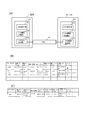
- FIG. 3A is a diagram illustrating a configuration relating to the VPN device of the terminal 1 and the first gateway (GW1) 51 of the data center 50.
- the VPN setting unit 512 of the VPN device 511 of the first gateway 51 controls the VPN setting and stores the setting information in the VPN information storage unit 513.
- the VPN communication control unit 514 performs communication control of data communication via the VPN tunnel by control of VPN tunnel connection (IKE phases 1 and 2), encryption and decryption.
- the terminal 1 has the same configuration.
- the VPN setting unit 512 when setting a VPN tunnel in the first gateway 51, the VPN setting unit 512 identifies a VPN identifier (VPN tunnel identifier) for identifying the VPN, a pre-shared key (pre-shared key), and identification of the communication partner. (Name, etc.), authentication algorithm, encryption algorithm, IKE keep alive (reconnect when VPN is disconnected). Further, a route network address (IP address + net mask) is set as route information. Furthermore, the presence / absence of user authentication by XAUTH (eXtended AUTHentication) and the presence / absence of NAT traversal are set. XAUTH performs user authentication by encrypting and exchanging the user name and password between the VPN remote client and server after IKE phase 1 (device authentication).
- VPN setting unit 102 of the VPN apparatus 101 of the terminal 1 as a VPN client setting, a setting name, a pre-shared key (pre-shared key), a client name, a connection destination gateway (IP address or name), an authentication algorithm, an encryption Set the algorithm, destination network, presence / absence of NAT traversal, etc.
- ⁇ IKE encryption algorithms (3DES-CBC (Cipher Block Chaining Mode), DES-CBC, AES (Advanced Encryption Standard) -CBC), ⁇ IKE hash algorithm (MD5, SHA-1), ⁇ ESP encapsulation (to send and receive by encapsulating with UDP to enable IPsec communication in an environment where NAT cannot pass ESP), ⁇ Pre-shared-key, -SA policy (for example, policy identifier (Policy_ID), VPN gateway identifier (gateway), authentication header (AH), authentication algorithm, local device network identifier, remote network identifier, etc.) Transport mode definition (source port list, destination port list), -At least one of presence / absence of NAT traversal, etc. is stored (but not limited to the above). These pieces of information may be set by a command input by the VPN setting unit.
- These pieces of information may be set by a command input by the VPN setting unit.
- FIG. 3B is a diagram illustrating an example of VPN management information set by the VPN setting unit 512 and stored in the VPN information storage unit 513.
- VPN is assigned a VPN identifier and is managed for each terminal (user).
- the connection partner IP address is the private IP address (local IP address) of the VPN client (terminal 1) issued by the first gateway 51 or the like (DHCP server).
- the terminal ID / name of the connection destination may be the ID of the terminal 1 (for example, IMSI (International Mobile Subscriber Identity)) or user ID.
- the device address is the IP address on the VPN tunnel side of the first gateway 51 (router).
- the connection network is a destination network for VPN communication, and is a network address on the VPN tunnel side. In the example of FIG.
- the IP address assigned to the terminal 1 in FIG. 3A is 100.1.100.1, and the IP address assigned to the terminal 1 is 100.1.100.1 (netmask: 32).
- a packet addressed to the terminal 1 from the data center 50 is route-searched by a wireless LAN router connected to the WAN 1 (31), and is transmitted to the terminal 1 via a VPN via a wireless LAN access point connected to the corresponding port.
- VPN management information in addition to the IP address, terminal ID, etc.
- the name of the wireless LAN access point to which the terminal 1 is connected (Access (Point Name : APN) or port information of a wireless LAN router to which the wireless LAN access point is connected may be provided.
- APN Access (Point Name : APN)
- port information of a wireless LAN router to which the wireless LAN access point is connected may be provided.
- FIG. 3B the VPN information shown in FIG. 3B is an example, and it is needless to say that the VPN information is not limited to such a configuration.
- FIG. 3C is a diagram illustrating an example of VPN management information set by the VPN setting unit 102 of the terminal 1 which is a VPN client and stored in the VPN information storage unit 103.
- the connection destination may be specified by the host name of the base (for example, FDNQ (Fully Qualified Domain Name) of the data center 50).
- the connection network is a destination network of VPN communication from the VPN client (terminal 1), and is a network address on the VPN tunnel side of the first gateway 51.
- the connection network is assumed to have an address on the VPN side of the first gateway 51: 100.1.1.0/24 (net mask: 24).
- VPN communication control units 514 and 104 terminate VPN tunnels, manage security keys, manage data transfers via VPN tunnels, control transmission / reception data transmission as VPN tunnel endpoints or routers, and encrypt data Packet transfer by encapsulation and packet decapsulation and decoding.
- IPv4 Internet Protocol Version 4
- IPv4 Internet Protocol Version 4
- IP addresses in FIGS. 3B and 3C are fictitious addresses.
- an L2TP tunnel is arrange
- Connection control messages and session control messages are used to establish the L2TP tunnel.
- a tunnel is created by a connection control message, and then a session is established by a session control message.
- VPNs are allocated on a terminal basis (terminal ID, common account).
- the terminal ID / name column may be a user account (for example: “aaa@example.com”) provided to the user by the CLIDE operator of the data center 50 in addition to the user ID.
- VPN management may use user-specific information (such as a user account or a Web mail address) in addition to the IP address of the terminal 1 (VPN client).
- the wireless LAN access point 41 transfers the access request packet from the terminal 1 to the main data center 50 via the WAN 1 (31).
- the first gateway (GW1) 51 of the data center 50 assigns an IP address (private IP address) to the terminal 1 and establishes a VPN tunnel 60.
- the VPN tunnel 60 is an IPsec tunnel, as described above, IKE SA establishment (IKE phase) 1, IPsec SA establishment (IKE phase 2), and encrypted communication on the IPsec SA are performed.
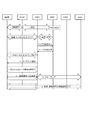
- FIG. 4 is a diagram for explaining an example of an initial attach process of the terminal 1 and a sequence for connecting to the connection destination 33 connected to the WAN 2 (32) in the system of the exemplary embodiment described with reference to FIG. is there.
- FIG. 4 schematically illustrates an example of an operation sequence in the terminal 1, the WLAN 40, the first gateway 51 (GW1), the vEPC 52, the second gateway (GW2) 53, and the WAN2 (32) in FIG. .
- the number given to each sequence operation is a sequence number for explanation.
- the terminal 1 establishes a connection with the wireless LAN (WLAN) 40, and performs authentication / authorization (Authentication & Authorization) by HSS / AAA (not shown) in the vEPC 52, for example.
- the first gateway 51 is a gateway to which the terminal 1 connects when accommodating a wireless LAN 40 that is non-3GPP wireless access (UntrustedtrustNon-3GPP IP Access) that is not reliable in security. Is set as.
- the first gateway (GW1) 51 transmits a bearer setting request (Create ⁇ ⁇ Session Request) to the vEPC 52, for example.
- a PGW to be connected to the packet data network of the connection destination is selected, and a GTP (GPRS (General Packet Radio System) Tunneling Protocol) tunnel is established on the S8 interface between the SGW and the PGW.
- GTP General Packet Radio System
- a bearer setting response (Create Session Response) is transmitted from the vEPC 52 to the first gateway (GW1) 51.
- the IP address assigned to the terminal 1 is notified by the IKEv2 message from the first gateway (GW1).
- IP connection from terminal 1 to the first gateway (GW1) is set at this point.
- the above corresponds to the sequence of the attach process.
- the setting of the connection with the connection destination 33 on the WAN 2 side is completed from the terminal 1 via the VPN and the vEPC 52 of the data center 50.
- the packet in the downlink direction from the WAN 2 (32) side to the terminal 1 is transferred to the first gateway 51 (GW1) by the PGW in the vEPC 52 in accordance with a policy such as PCRF. (GW1) to the terminal 1 via the VPN tunnel 60.
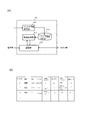
- FIG. 5A is a diagram showing an example of the configuration of the functional block 54 in FIG.
- the function block 54 is A communication unit 541 that receives the packet and causes the permitted packet to communicate under the control of the transfer control unit 542;
- a filter information storage unit 543 for storing filter information for controlling packet discard and passage;
- the address, port, and protocol are extracted from the header of the packet received by the communication unit 541, checked against the conditions of the filter information storage unit 543, whether the packet is rejected or permitted, and the determination result is notified to the communication unit 541.
- a filter information setting unit 544 for setting filter information in the filter information storage unit 543; It has.
- the filter information setting unit 544 may set the filter information in the filter information storage unit 543 by a management terminal (not shown) in the data center 50 in FIG. .
- a management terminal not shown
- the functional block 54 is equivalently provided for each terminal 1.
- FIG. 5B shows an example of packet filter information as the configuration of the filter information storage unit 543 in FIG.
- the type handling of packets that match the filter conditions: passing or discarding
- direction filter evaluation direction: WAN2 is UP from wireless LAN, and wireless LAN is DOWN from WAN2)
- Protocol IP protocol of the packet to be filtered
- source address source IP protocol of the packet to be filtered
- transmission port source port of the packet to be filtered
- destination address filter target and Destination IP protocol
- destination port destination port of packet to be filtered
- the filter information of FIG. 5B is filtered from the filter information setting unit 544 for each terminal (subscriber).
- the filter information setting unit 544 For each terminal (subscriber), the filter information of FIG. 5B is filtered from the filter information setting unit 544 for each terminal (subscriber).
- the terminal 1 (subscriber) may be managed using a user account assigned to the user of the terminal 1 on the data center 50 side.
- FIG. 6 is a diagram illustrating an example of the above-described embodiment.
- an IPsec tunnel is set between the ePDG 527 of the vEPC 52 of the data center 50 and the terminal 1.
- the ePDG 527 functions as a VPN gateway and terminates the VPN tunnel.
- ePDG527 functions as a VPN gateway, Establishing a VPN (IPsec) tunnel with the terminal 1 via the wireless LAN 40 and WAN 1 (31), Security parameter negotiation, ⁇ User authentication, ⁇ Assign private IP address to terminal 1, Data encryption and decryption, ⁇ Security key management, ⁇ Management of data transfer via VPN tunnel, ⁇ Management of transmission and reception data transmission as the end point of VPN tunnel.
- IPsec VPN
- the assignment of the private IP address to the terminal 1 may be performed by the PGW 522 of the vEPC 52.
- the terminal 1 transmits an EAP message to the ePDG 527 by IKEV2, relays it to the 3GPP AAA server 525 of the vEPC 52, and performs EAP-SIM / EAP-AKA authentication.
- the ePDG 527 and the PGW 522 of the vEPC 52 are connected by a GTP or PMIPv6 tunnel.
- the proxy mobile IP (PMIPv6 tunnel)
- PMIPv6 tunnel When the proxy mobile IP (PMIPv6 tunnel) is used between the PGW 22 and the ePDG 27 in the vEPC 52, when the IPsec tunnel is established between the terminal 1 and the ePDG 27 of the vEPC 52, the ePDG 27 performs a proxy binding update (Proxy Binding Update). Send to PGW22.
- the proxy binding update Proxy Binding Update
- the destination of the incoming call to the terminal 1 is switched to the ePDG 27 of the vEPC 52, and the incoming call is notified to the terminal 1 via the VPN tunnel 60 and the WLAN 40.
- the PGW 522 is connected to a packet filter 529 having, for example, a TFT (Traffic Flow Template) related to an EPS bearer.
- the packet filter 529 functions as the functional block 54 in FIG. 2 and is provided for each terminal 1. That is, the filter information (packet discard etc.) in the packet filter 529 is provided for each terminal 1 (subscriber) as described above.
- the packet filter 529 may be arranged in the PGW 522.
- the setting (addition, correction, deletion, etc.) of the filter information in the downstream direction from the WAN2 to the terminal 1 and the upstream direction from the terminal 1 to the WAN2 is performed by modifying the bearer resource from the terminal 1, as described above. You may make it perform with the request request
- the setting of filter information in the packet filter 529 may be performed from the terminal 1 when a connection request process such as an Attach Request is performed, or when a predetermined event occurs.
- the packet filter 529 may be configured to have a filtering function in the application layer or a stateful inspection function.
- the packet filter 529 may be provided with an incoming call rejection list for rejecting incoming calls from the WAN 2 (32).
- WAN2 When WAN2 (32) is configured with IMS, P-CSCF (Proxy-Call Session Function ⁇ ⁇ ) connected to vEPC52, Serving-CSCF, content filtering that analyzes and blocks voice content, and inappropriate numbers It is good also as a structure provided with the incoming call rejection list which prohibits the incoming call from.
- the SGW 521 is connected to access of the data center 50 from a 3GPP access network (not shown).
- another functional block 54 in addition to the packet filter 529.
- a data compressor 530 is connected to the ePDG 527, and in the data compressor 530, a packet transferred to the terminal 1 according to the capability information or model information of the terminal 1. You may make it vary the compression rate of the data of a payload part.
- the data compressor 530 may be connected to the PGW 522 to variably control the compression rate of data transmitted to the WAN 2 (32).
- ePDG 527 and PGW 522 are implemented by vEPC 52, but the cloud operator borrowed ePDG 27 and PGW 22 (FIG. 1) of MNO (Mobile Network Operator) as MVNO (Mobile Virtual Network Operator), for example. May be.
- MNO Mobile Network Operator
- MVNO Mobile Virtual Network Operator
- Wi-Fi (registered trademark) -Calling from the terminal 1, a VPN 60 (IPsec tunnel) is established between the terminal 1 and the ePDG 527 via the WLAN 40 and WAN 1 (31), and GTP is connected between the ePDG 527 and the PGW 522.
- a / PMIPv6 tunnel is established and connected to the connection destination from the PGW 522 via, for example, the WAN 2 (32) made of IMS.
- Wi-Fi (registered trademark) -Calling is controlled as a communication service by a cloud operator (MVNO) and provides a secure connection. Protection is provided.
- MVNO cloud operator
- Protection is provided.
- the PGW 522 may have both the function as the second gateway (GW2) 53 of FIG.
- FIG. 7 is a diagram schematically illustrating the initial attach process of the terminal 1 and the communication connection sequence to the connection destination 33 connected to the WAN 2 (32) in the system of FIG.
- FIG. 7 illustrates an example of an operation sequence in the connection destination 33 on the terminal 1, WLAN 40 (WLAN AP), ePDG 527, PGW 522, HSS 524 / AAA server 525, PCRF 526, WAN 2 (32) side in FIG.
- the number given to each sequence operation is a sequence number for explanation.
- GW1 first gateway
- PGW 522 is replaced with the second gateway (GW2)
- the operation described with reference to FIG. 4 can be partially supported.
- the terminal 1 establishes a connection with the wireless LAN (WLAN) 40, and performs authentication / authorization (Authentication & Authorization) by the HSS524 / AAA 525 in the vEPC 52, for example.
- WLAN wireless LAN
- authentication / authorization Authentication & Authorization
- the ePDG 527 uses the LMA (Local Mobility) to establish a binding between the Proxy Binding Update (the mobile node's home network prefix and the MAG (Mobile Access Gateway) to which the mobile node is connected) to the PGW 522. Request message sent to Anchor).
- LMA Local Mobility
- the PGW 522 performs an IP connection access network (IP-CAN (Connection-Access Network)) session establishment procedure in cooperation with the PCRF 526.
- IP-CAN Connection-Access Network
- the PGW 522 notifies the AAA server 525 of the PGW identification information (PGW ID), and the AAA server 525 notifies the HSS 524 of the ID of the PGW 522 and the APN (Access Point Name) corresponding to the terminal 1 for registration.
- PGW ID PGW identification information
- APN Access Point Name
- the PGW 522 performs a proxy binding update process and creates a binding cache entry corresponding to the terminal 1. Thereby, in the PGW 522, the packet addressed to the terminal 1 is transmitted to the ePDG 527 according to the content held in the binding cache entry. The PGW 522 transmits a proxy binding response (Proxy Binding Ack) to the ePDG 527.
- a proxy binding response Proxy Binding Ack
- the ePDG 52 notifies the terminal 1 of the IP address with an IKEv2 message.
- IPsec tunnel is established between the terminal 1 and the ePDG 527, and a tunnel such as PMIP (Proxy-> Mobile-> Internet-> Protocol) is established between the ePDG 527 and the PGW 522.
- PMIP Proxy-> Mobile-> Internet-> Protocol
- connection destination 33 When a connection request to the connection destination 33 is received from the terminal 1 side to the WAN 2 (32) side from the ePDG 527 via the PMIP tunnel, IP routing from the PGW 522 to the connection destination (WAN 2 side) is performed.
- the SIP message from the terminal 1 is transmitted to the P-CSCF of the IMS via the second gateway (GW2) 53, and for example PSTN (Public Switched Telephone Networks) via the S-CSCF, MGCF, MGW or the like.
- the connection destination 33 may be connected.
- the S-CSCF may be connected to the connection destination 33 that is connected to the Internet or another IMS.
- IMS P-CSCF and PGW 522 communicate by IPsec (VPN).
- the setting of the connection with the connection destination 33 on the WAN 2 side is completed from the terminal 1 via the VPN and the vEPC 52 of the data center 50.
- the packet in the downlink direction from the WAN 2 (32) side to the terminal 1 is transferred by the PGW 522 in the vEPC 52 to the ePDG 527 via the PIMP tunnel based on the binding cache entry, and from the ePDG 527 via the VPN tunnel 60 to the terminal 1 1 is transferred.
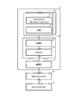
- a virtual machine (Virtual VM) 571 on the server 57 in the data center 50 is connected to a virtual port A of a virtual switch (vSwitch) 576 via a virtual network interface controller (vNIC) 575, and the virtual switch (vSwitch) A virtual port of 576: B is connected to a physical port: C of a physical switch (Physical Switch) 58 via a physical NIC (pNIC) 577, and a data center of the physical switch (Physical Switch) 58 is connected to a data center of D. 50 is connected to a network 55 such as a LAN.
- a network 55 such as a LAN.
- the virtual machine 571 includes a guest OS (Operating System) 573 and an application 572, and realizes part or all of the functions of the EPC network node (for example, the function of the ePDG 527 in FIG. 6 or the function of other nodes).
- the virtual network 59 is connected to the router 56 of FIG. 6, for example.
- the functional block 54 in FIG. 2 may be configured by the virtual machine (Virtual VM) 571 in FIG.
- a virtual NIC (vNIC), a virtual switch (vSwitch), and the like are provided by a hypervisor 574, which is a virtualization mechanism on the server 57.
- the physical switch 58 may be configured with an L2 (Layer 2) switch, and the network 59 may be configured with a virtual network such as a VLAN (Virtual LAN).
- L2 Layer 2
- VLAN Virtual LAN
- the virtual machine 571 in FIG. 10 may implement the functional block 54 in FIG. 2 and the virtual network 55 in FIG. 2 may be configured with a network 59 such as a VLAN.
- NFV Network Function Virtualization
- management units NFV Orchestrator (NFVO)
- VNF Virtualized Network Function Manager
- FIG. 9 NFV (Network Function Virtualization) management units (NFV Orchestrator (NFVO), VNF (Virtualized Network Function) Manager, etc.) such as a manager that manages and integrates network function virtualization are omitted.
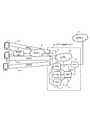
- FIG. 8 is a diagram for explaining another embodiment.
- terminals 1-1, 1-2, and 1-3 are accessing one wireless LAN access point 41 and vEPC 52 of the data center 50 of the cloud operator.
- the data center 50 manages the VPN for each of the terminals 1-1 to 1-3, or for each user account of the terminal, and simultaneously accommodates the plurality of VPN tunnels 60-1 to 60-3. You may do it. Note that the configuration, operation, and the like of each of the terminals 1-1 to 1-3 are the same as in the above embodiment.
- the data center 50 includes a plurality of functional blocks 54-1 to 54-3 and a plurality of functional blocks 54-1 to 54- that are connected to the VPNs 60-1 to 60-3 via the first gateway (GW1) 51, respectively. 3 and a functional block 54-4 connected between the second gateway (GW2) 53.
- GW1 first gateway
- GW2 second gateway
- the functional blocks 54-1 to 54-3 may be configured to set packets to be filtered (parental control, access denial, etc.) from the user side.
- the function block 54-4 may set a packet to be filtered (for example, a packet from a specific region, site, etc.) from a maintenance terminal or a control device (not shown) of the cloud operator of the data center 50. .
- the function blocks 54-1 to 54-3 When the function blocks 54-1 to 54-3 are set from the user side, they may be set by a request message to the data center 50 from the terminal 1 side.
- the function can be executed from the maintenance terminal or the control device (not shown) of the cloud operator that owns the data center 50.
- Filter targets may be set for the blocks 54-1 to 54-3.
- the plurality of terminals When a plurality of terminals are connected to one wireless LAN access point 41, the plurality of terminals share radio waves and communicate, and when a plurality (multiple) terminals access one wireless LAN access point 41, The throughput (data transfer amount per unit time, etc.) of each terminal decreases. Therefore, when a plurality of terminals are connected to one wireless LAN access point 41 and access is concentrated, the connection destination of the plurality of terminals is changed to a wireless access point different from the wireless access point where access is concentrated.
- a configuration including a wireless LAN controller (not shown) for performing distribution and load distribution control may be employed.
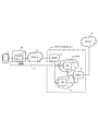
- FIG. 9 is a diagram for explaining still another embodiment of the present invention.
- a function block 54-2 in the vEPC 52 is provided in addition to the function block 54-1 on the virtual network 55 between the first gateway (GW1) and the second gateway (GW2).
- the function block 54-1 performs filtering of data communication packets.
- the function block 54-2 in the vEPC 52 permits, for example, rejecting an incoming call from a telephone number designated by the user, and accepting an SMS or incoming call in which the telephone number designated by the user is registered.
- the function block 54-1 and the function block 54-2 are equivalently configured such that filter information or the like is set for each terminal 1 and equivalently provided for each terminal 1.
- the function block 54-2 may virtualize at least a part of the functions of the IMS SIP server and connect to, for example, the PGW to realize control of call rejection or permission.
- the function of the function block 54-2 may be added to the packet filter (529 in FIG. 6) that manages the TFT with the PGW of the vEPC 52.
- the function block 54-1 between the first gateway (GW1) and the second gateway (GW2) is used to store packet data from the WAN2 (32) to the terminal 1 side, capability information of the terminal 1, etc. (SDP (Session Description)
- SDP Session Description
- the compression rate of the compression encoding is changed so as to be adapted to the capability, model, etc. on the terminal 1 side based on the capability exchange by Protocol), etc., and then transferred from the first gateway to the terminal 1 Good.
- the functional block 54-1 transcodes the packet data (compression encoded data) received by the second gateway from the WAN 2 (32) once decoded and re-encoded to change the compression rate. Processing may be performed. In transcoding processing, the bit rate, frame rate, resolution, and the like may be changed. For example, the data size downloaded to the terminal 1 can be compressed to reduce the network load, improve the transfer efficiency, and effectively use the bandwidth.
- Non-Patent Document 1 is incorporated herein by reference.
- the embodiments and examples can be changed and adjusted based on the basic technical concept.
- Various combinations or selections of various disclosed elements are possible within the scope of the claims of the present invention. . That is, the present invention of course includes various variations and modifications that could be made by those skilled in the art according to the entire disclosure including the claims and the technical idea.
- a communication system comprising:
- Appendix 2 In the data center, The communication system according to appendix 1, wherein the virtual network includes a virtual packet core network in which at least a part of a function of the packet core network is virtualized.
- the functional block is A first functional block connected between the first gateway and the second gateway; A second functional block connected to the virtual packet core network;
- the communication system according to appendix 2 including at least one of the above.
- the functional block is In addition to packet filters that control packet blocking and passage, The communication system according to any one of appendices 1 to 3, further including a functional block that controls an incoming call to the terminal and a text message access rejection and permission.
- the functional block is A functional block for controlling compression of data in the payload portion of at least one of the packet input from the second wide area network side and the packet input from the terminal side via the first wide area network
- the communication system according to any one of appendices 1 to 3, further comprising:
- the functional block is Appendices 1 to 5 each having a function block that is provided corresponding to the terminal and in which filtering of packets to the terminal and / or denial of access to the terminal and access to a message and permission are set for each terminal.
- the communication system according to any one of the above.
- the terminal communicates with a connection destination from the VPN via the virtual packet core network of the data center and the second wide area network, Of the incoming calls or messages from the second wide area network side to the terminal, the incoming calls or messages permitted by the second functional block connected to the virtual packet core network of the data center are The communication system according to attachment 3, which is transmitted to the terminal via a VPN.
- Appendix 8 In a data communication service provided to the terminal via the wireless LAN, The terminal connects to the second wide area network from the VPN via the virtual network of the data center; Data from the second wide area network side to the terminal is filtered by the first functional block connected between the first gateway and the second gateway of the data center, and allowed packets The communication system according to appendix 3 or 7, wherein is transmitted to the terminal via the VPN.
- the functional block is Comprising first to Nth functional blocks respectively connected to the first to Nth VPNs terminated at the first gateway;
- An N + 1th functional block connected at one end to the first to Nth functional blocks and connected at the other end to the second gateway;
- the setting of the first to Nth functional blocks is performed from the user side of the first to Nth terminals,
- the communication system according to appendix 1 or 2, wherein the setting of the (N + 1) th functional block is performed on the data center side.
- Appendix 10 In the data center, The communication system according to any one of appendices 1 to 9, wherein the first gateway manages the VPN with the terminal in a terminal unit or a user unit of the terminal.
- a functional block that performs filtering control of A communication device comprising:
- Appendix 12 The communication device according to appendix 11, wherein the virtual network includes a virtual packet core network in which at least a part of a function of the packet core network is virtualized.
- the functional block is A first functional block connected between the first gateway and the second gateway; A second functional block connected to the virtual packet core network; The communication device according to appendix 12, including at least one of them.
- the functional block includes: 14.
- the functional block is A functional block for controlling compression of data in the payload portion of at least one of the packet input from the second wide area network side and the packet input from the terminal side via the first wide area network
- the communication device according to any one of appendices 11 to 13, further comprising:
- the functional block is Appendices 11 to 15 provided corresponding to the terminal, each having a functional block for setting filtering of the packet to the terminal and / or refusal and permission of incoming call and message access to the terminal.
- the communication device according to any one of the above.
- the terminal In a voice call or text message service provided to the terminal via the wireless LAN, The terminal communicates with a connection destination from the VPN via the virtual packet core network of the communication device and the second wide area network, Of the incoming calls or messages from the second wide area network side to the terminal, the incoming calls or messages permitted by the second functional block connected to the virtual packet core network of the communication device are the The communication device according to attachment 13, which is transmitted to the terminal via a VPN.
- Appendix 18 In a data communication service provided to the terminal via the wireless LAN, The terminal connects to the second wide area network from the VPN via the virtual network of the data center; The data from the second wide area network side to the terminal is filtered and permitted by the first functional block connected between the first gateway and the second gateway of the communication device. 18. The communication device according to appendix 13 or 17, wherein is transmitted to the terminal via the VPN.
- N is an integer greater than or equal to 2 terminals connected to one wireless LAN access point and the first gateway of the communication device are connected via first to Nth VPNs
- the functional block is Comprising first to Nth functional blocks respectively connected to the first to Nth VPNs terminated at the first gateway;
- An N + 1th functional block connected at one end to the first to Nth functional blocks and connected at the other end to the second gateway;
- the setting of the first to Nth functional blocks is performed from the user side of the first to Nth terminals,
- the communication apparatus according to appendix 11 or 12, wherein the setting of the (N + 1) th functional block is performed on the communication apparatus side.
- Appendix 20 The communication device according to any one of appendices 11 to 19, wherein the first gateway manages the VPN with the terminal in a terminal unit or a user unit of the terminal.
- a first wide area network (Wide Area Network) is interposed between a wireless LAN (Local Area Network) to which the terminal is connected and a first gateway of a data center and the terminal via the wireless LAN.
- VPN Virtual Private Network
- a communication method for filtering at least one of the packets is interposed between a wireless LAN (Local Area Network) to which the terminal is connected and a first gateway of a data center and the terminal via the wireless LAN.
- VPN Virtual Private Network
- Appendix 23 The appendix 21 or 22, wherein the data center controls compression of data in a payload portion of at least one of a packet input from the second wide area network side and a packet input from the terminal side. Communication method.
- Appendix 24 In the data center, the functional block is provided corresponding to the terminal, 24.
- a terminal provided with means for receiving via.
- a computer included in a terminal connected to a data center via a wireless LAN (Local Area Network) and a first wide area network (Wide Area Network) A process for establishing a VPN (Virtual Private Network) via the wide area network via the wireless LAN between the data center and the terminal; A process for connecting to a second wide area network via a virtual network provided in the data center via the VPN and virtualizing at least a part of the functions of the packet core network; Out of incoming calls to the terminal input to the data center from the second wide area network side or data addressed to the terminal, incoming calls or data filtered in the data center are sent via the VPN.
Landscapes
- Engineering & Computer Science (AREA)
- Computer Security & Cryptography (AREA)
- Computer Networks & Wireless Communication (AREA)
- Signal Processing (AREA)
- Computing Systems (AREA)
- Computer Hardware Design (AREA)
- General Engineering & Computer Science (AREA)
- Business, Economics & Management (AREA)
- Accounting & Taxation (AREA)
- Power Engineering (AREA)
- Data Exchanges In Wide-Area Networks (AREA)
- Mobile Radio Communication Systems (AREA)
Abstract
La présente invention fournit la protection nécessaire à un terminal qui est connecté à un centre de données via un LAN sans fil et un réseau étendu, et permet de fournir une communication sécurisée. Dans un système de communication selon la présente invention, un centre de données comprend : une première passerelle par laquelle le centre de données et un terminal sont connectés via un LAN sans fil par l'intermédiaire d'un VPN pour un premier réseau étendu ; une seconde passerelle qui est connectée à un second réseau étendu (WAN2) ; un réseau virtuel qui est connecté à la première passerelle et à la seconde passerelle ; et un bloc de fonction qui exécute un filtrage d'au moins des paquets entrés, du côté du second réseau étendu (WAN2) à la seconde passerelle.
Priority Applications (2)
| Application Number | Priority Date | Filing Date | Title |
|---|---|---|---|
| US15/745,311 US11870604B2 (en) | 2015-07-17 | 2016-07-14 | Communication system, communication device, communication method, terminal, non-transitory medium for providing secure communication in a network |
| JP2017529865A JP6451850B2 (ja) | 2015-07-17 | 2016-07-14 | 通信システム、通信装置、通信方法、端末、プログラム |
Applications Claiming Priority (2)
| Application Number | Priority Date | Filing Date | Title |
|---|---|---|---|
| JP2015143405 | 2015-07-17 | ||
| JP2015-143405 | 2015-07-17 |
Publications (1)
| Publication Number | Publication Date |
|---|---|
| WO2017014164A1 true WO2017014164A1 (fr) | 2017-01-26 |
Family
ID=57834331
Family Applications (1)
| Application Number | Title | Priority Date | Filing Date |
|---|---|---|---|
| PCT/JP2016/070907 Ceased WO2017014164A1 (fr) | 2015-07-17 | 2016-07-14 | Système de communication, dispositif de communication, procédé de communication, terminal, et programme |
Country Status (3)
| Country | Link |
|---|---|
| US (1) | US11870604B2 (fr) |
| JP (1) | JP6451850B2 (fr) |
| WO (1) | WO2017014164A1 (fr) |
Cited By (4)
| Publication number | Priority date | Publication date | Assignee | Title |
|---|---|---|---|---|
| WO2018216435A1 (fr) * | 2017-05-23 | 2018-11-29 | 株式会社Nttドコモ | Système de communication et procédé de communication |
| WO2020122040A1 (fr) * | 2018-12-10 | 2020-06-18 | フリービット株式会社 | Système de gestion de connexion internet pour dispositif de communication d'informations, procédé associé et programme de gestion de connexion internet installé dans un dispositif de communication d'informations |
| CN114285900A (zh) * | 2021-12-09 | 2022-04-05 | 中国联合网络通信集团有限公司 | 调度系统、认证方法、调度方法、装置、服务器及介质 |
| WO2023162147A1 (fr) * | 2022-02-25 | 2023-08-31 | 日本電信電話株式会社 | Dispositif de communication, système de communication, procédé de communication, et programme |
Families Citing this family (9)
| Publication number | Priority date | Publication date | Assignee | Title |
|---|---|---|---|---|
| CN107360089B (zh) * | 2016-05-10 | 2021-03-19 | 新华三技术有限公司 | 一种路由建立方法、业务数据转换方法及装置 |
| KR101846079B1 (ko) * | 2016-07-15 | 2018-04-05 | 주식회사 케이티 | Nfv 환경에서의 가상 cpe 서비스 제공 시스템, 및 이를 위한 nfv 클라우드 |
| US10630657B2 (en) * | 2017-03-02 | 2020-04-21 | ColorTokens, Inc. | System and method for enhancing the security of data packets exchanged across a computer network |
| CN109450657B (zh) * | 2019-01-15 | 2019-12-27 | 深圳联想懂的通信有限公司 | 一种智能物联网通信服务系统和方法 |
| JP7234726B2 (ja) * | 2019-03-20 | 2023-03-08 | 富士フイルムビジネスイノベーション株式会社 | 通信装置、通信システム、及びプログラム |
| TWI727493B (zh) * | 2019-11-08 | 2021-05-11 | 瑞昱半導體股份有限公司 | 一種閘道器控制晶片及其網路封包處理方法 |
| WO2022040581A1 (fr) * | 2020-08-20 | 2022-02-24 | Geoverse, LLC | Réseau cellulaire privé permettant une extension continue d'accessibilité de dispositifs autocommutateurs privés (pbx) auprès de dispositifs distants |
| EP4311289A1 (fr) * | 2022-07-22 | 2024-01-24 | Anam Technologies Ltd | Messagerie sms sécurisée d'application à personne |
| US12389215B2 (en) * | 2022-07-28 | 2025-08-12 | T-Mobile Usa, Inc. | WiFi call identification for roaming subscribers |
Citations (3)
| Publication number | Priority date | Publication date | Assignee | Title |
|---|---|---|---|---|
| JP2004135248A (ja) * | 2002-08-09 | 2004-04-30 | Fujitsu Ltd | 仮想閉域網システム |
| JP2006033443A (ja) * | 2004-07-16 | 2006-02-02 | Nec Fielding Ltd | インターネット接続システム、方法およびプログラム |
| JP2010231396A (ja) * | 2009-03-26 | 2010-10-14 | Oki Networks Co Ltd | 通信システム、通信装置及び認証装置 |
Family Cites Families (10)
| Publication number | Priority date | Publication date | Assignee | Title |
|---|---|---|---|---|
| JP4201466B2 (ja) * | 2000-07-26 | 2008-12-24 | 富士通株式会社 | モバイルipネットワークにおけるvpnシステム及びvpnの設定方法 |
| US7673048B1 (en) * | 2003-02-24 | 2010-03-02 | Cisco Technology, Inc. | Methods and apparatus for establishing a computerized device tunnel connection |
| US7808906B2 (en) * | 2004-07-23 | 2010-10-05 | Citrix Systems, Inc. | Systems and methods for communicating a lossy protocol via a lossless protocol using false acknowledgements |
| JP4706542B2 (ja) * | 2006-04-10 | 2011-06-22 | 株式会社日立製作所 | 通信装置 |
| EP2244495B1 (fr) * | 2009-04-20 | 2012-09-19 | Panasonic Corporation | Optimisation de route d'un chemin de données entre des noeuds de communication utilisant un agent d'optimisation |
| CN101582830B (zh) * | 2009-06-22 | 2011-12-21 | 杭州华三通信技术有限公司 | 一种实现跨虚拟专用网互访的装置及方法 |
| US9521145B2 (en) * | 2011-10-17 | 2016-12-13 | Mitel Mobility Inc. | Methods and apparatuses to provide secure communication between an untrusted wireless access network and a trusted controlled network |
| JP2014195167A (ja) | 2013-03-28 | 2014-10-09 | Nippon Telegraph & Telephone East Corp | 電話システム及びその方法 |
| EP3028528A4 (fr) * | 2013-08-27 | 2017-05-03 | Huawei Technologies Co., Ltd. | Système et procédé de virutalisation de fonction de réseau mobile |
| WO2015103338A1 (fr) * | 2013-12-31 | 2015-07-09 | Lookout, Inc. | Sécurité de réseau basée sur des nuages |
-
2016
- 2016-07-14 WO PCT/JP2016/070907 patent/WO2017014164A1/fr not_active Ceased
- 2016-07-14 US US15/745,311 patent/US11870604B2/en active Active
- 2016-07-14 JP JP2017529865A patent/JP6451850B2/ja active Active
Patent Citations (3)
| Publication number | Priority date | Publication date | Assignee | Title |
|---|---|---|---|---|
| JP2004135248A (ja) * | 2002-08-09 | 2004-04-30 | Fujitsu Ltd | 仮想閉域網システム |
| JP2006033443A (ja) * | 2004-07-16 | 2006-02-02 | Nec Fielding Ltd | インターネット接続システム、方法およびプログラム |
| JP2010231396A (ja) * | 2009-03-26 | 2010-10-14 | Oki Networks Co Ltd | 通信システム、通信装置及び認証装置 |
Cited By (12)
| Publication number | Priority date | Publication date | Assignee | Title |
|---|---|---|---|---|
| WO2018216435A1 (fr) * | 2017-05-23 | 2018-11-29 | 株式会社Nttドコモ | Système de communication et procédé de communication |
| JPWO2018216435A1 (ja) * | 2017-05-23 | 2020-03-26 | 株式会社Nttドコモ | 通信システム及び通信方法 |
| JP7166251B2 (ja) | 2017-05-23 | 2022-11-07 | 株式会社Nttドコモ | 通信システム及び通信方法 |
| WO2020122040A1 (fr) * | 2018-12-10 | 2020-06-18 | フリービット株式会社 | Système de gestion de connexion internet pour dispositif de communication d'informations, procédé associé et programme de gestion de connexion internet installé dans un dispositif de communication d'informations |
| JPWO2020122040A1 (ja) * | 2018-12-10 | 2021-10-28 | フリービット株式会社 | 情報通信機器用のインターネット接続管理システム及びその方法、情報通信機器にインストールされるインターネット接続管理プログラム |
| JP7432524B2 (ja) | 2018-12-10 | 2024-02-16 | フリービット株式会社 | 情報通信機器用のインターネット接続管理システム及びその方法、情報通信機器にインストールされるインターネット接続管理プログラム |
| US11979377B2 (en) | 2018-12-10 | 2024-05-07 | Freebit Co., Ltd. | Internet connection management system for information communication device, method therefor, and internet connection management program installed in information communication device |
| CN114285900A (zh) * | 2021-12-09 | 2022-04-05 | 中国联合网络通信集团有限公司 | 调度系统、认证方法、调度方法、装置、服务器及介质 |
| CN114285900B (zh) * | 2021-12-09 | 2023-10-03 | 中国联合网络通信集团有限公司 | 调度系统、认证方法、调度方法、装置、服务器及介质 |
| WO2023162147A1 (fr) * | 2022-02-25 | 2023-08-31 | 日本電信電話株式会社 | Dispositif de communication, système de communication, procédé de communication, et programme |
| JPWO2023162147A1 (fr) * | 2022-02-25 | 2023-08-31 | ||
| JP7790544B2 (ja) | 2022-02-25 | 2025-12-23 | Ntt株式会社 | 通信装置、通信システム、通信方法、及びプログラム |
Also Published As
| Publication number | Publication date |
|---|---|
| JPWO2017014164A1 (ja) | 2018-07-05 |
| US11870604B2 (en) | 2024-01-09 |
| US20190013967A1 (en) | 2019-01-10 |
| JP6451850B2 (ja) | 2019-01-16 |
Similar Documents
| Publication | Publication Date | Title |
|---|---|---|
| JP6981491B2 (ja) | 通信システム、通信装置、通信方法、端末、プログラム | |
| JP6451850B2 (ja) | 通信システム、通信装置、通信方法、端末、プログラム | |
| JP7004383B2 (ja) | 通信システム、通信装置、通信方法、端末、プログラム | |
| US11115808B2 (en) | Consolidated control plane routing agent | |
| CN112020851B (zh) | 移动网络中的多接入分布式边缘安全性 | |
| EP3529968B1 (fr) | Système et procédé de sélection de noeud en fonction d'informations d'événements de session intermédiaire et de session finale | |
| CN108029017B (zh) | 通过受管理的公共WLAN接入进行安全wifi呼叫连接的方法 | |
| US9973338B2 (en) | Configuration of liveness check using internet key exchange messages | |
| US9215588B2 (en) | System and method for providing selective bearer security in a network environment | |
| CN110892745B (zh) | 用于服务提供商网络中的基于位置的安全性的方法和系统 |
Legal Events
| Date | Code | Title | Description |
|---|---|---|---|
| 121 | Ep: the epo has been informed by wipo that ep was designated in this application |
Ref document number: 16827724 Country of ref document: EP Kind code of ref document: A1 |
|
| ENP | Entry into the national phase |
Ref document number: 2017529865 Country of ref document: JP Kind code of ref document: A |
|
| NENP | Non-entry into the national phase |
Ref country code: DE |
|
| 122 | Ep: pct application non-entry in european phase |
Ref document number: 16827724 Country of ref document: EP Kind code of ref document: A1 |