WO2017014263A1 - Raccord de soupape à flotteur - Google Patents
Raccord de soupape à flotteur Download PDFInfo
- Publication number
- WO2017014263A1 WO2017014263A1 PCT/JP2016/071390 JP2016071390W WO2017014263A1 WO 2017014263 A1 WO2017014263 A1 WO 2017014263A1 JP 2016071390 W JP2016071390 W JP 2016071390W WO 2017014263 A1 WO2017014263 A1 WO 2017014263A1
- Authority
- WO
- WIPO (PCT)
- Prior art keywords
- float valve
- outer barrel
- sub
- assembly
- lid
- Prior art date
- Legal status (The legal status is an assumption and is not a legal conclusion. Google has not performed a legal analysis and makes no representation as to the accuracy of the status listed.)
- Ceased
Links
Images


Classifications
-
- E—FIXED CONSTRUCTIONS
- E21—EARTH OR ROCK DRILLING; MINING
- E21B—EARTH OR ROCK DRILLING; OBTAINING OIL, GAS, WATER, SOLUBLE OR MELTABLE MATERIALS OR A SLURRY OF MINERALS FROM WELLS
- E21B34/00—Valve arrangements for boreholes or wells
- E21B34/06—Valve arrangements for boreholes or wells in wells
- E21B34/10—Valve arrangements for boreholes or wells in wells operated by control fluid supplied from outside the borehole
-
- E—FIXED CONSTRUCTIONS
- E21—EARTH OR ROCK DRILLING; MINING
- E21B—EARTH OR ROCK DRILLING; OBTAINING OIL, GAS, WATER, SOLUBLE OR MELTABLE MATERIALS OR A SLURRY OF MINERALS FROM WELLS
- E21B34/00—Valve arrangements for boreholes or wells
- E21B34/06—Valve arrangements for boreholes or wells in wells
- E21B34/12—Valve arrangements for boreholes or wells in wells operated by movement of casings or tubings
-
- E—FIXED CONSTRUCTIONS
- E21—EARTH OR ROCK DRILLING; MINING
- E21B—EARTH OR ROCK DRILLING; OBTAINING OIL, GAS, WATER, SOLUBLE OR MELTABLE MATERIALS OR A SLURRY OF MINERALS FROM WELLS
- E21B2200/00—Special features related to earth drilling for obtaining oil, gas or water
- E21B2200/05—Flapper valves
-
- E—FIXED CONSTRUCTIONS
- E21—EARTH OR ROCK DRILLING; MINING
- E21B—EARTH OR ROCK DRILLING; OBTAINING OIL, GAS, WATER, SOLUBLE OR MELTABLE MATERIALS OR A SLURRY OF MINERALS FROM WELLS
- E21B25/00—Apparatus for obtaining or removing undisturbed cores, e.g. core barrels or core extractors
- E21B25/02—Apparatus for obtaining or removing undisturbed cores, e.g. core barrels or core extractors the core receiver being insertable into, or removable from, the borehole without withdrawing the drilling pipe
-
- E—FIXED CONSTRUCTIONS
- E21—EARTH OR ROCK DRILLING; MINING
- E21B—EARTH OR ROCK DRILLING; OBTAINING OIL, GAS, WATER, SOLUBLE OR MELTABLE MATERIALS OR A SLURRY OF MINERALS FROM WELLS
- E21B25/00—Apparatus for obtaining or removing undisturbed cores, e.g. core barrels or core extractors
- E21B25/10—Formed core retaining or severing means
- E21B25/14—Formed core retaining or severing means mounted on pivot transverse to core axis
Definitions
- the present invention relates to a float valve sub used for a drill string, and can be suitably used for, for example, a float valve sub in which a float valve assembly is detachably provided inside a bottom hole assembly.
- a technique for collecting a sample core of a formation is known.
- a drill bit is provided on an end circumference of a cylindrical structure called a drill string.
- the drill string penetrates into the formation by rotation or the like.
- a cylindrical formation sample is taken from the inside of the drill string.
- Patent Document 1 and Patent Document 2 disclose inventions of a flapper type float valve.
- a float valve using a flapper-type lid is provided inside the drill string.
- the float valve sub 2 has an outer barrel assembly and a float valve assembly.
- the float valve assembly is detachably disposed inside the outer barrel assembly.
- the float valve assembly has a first end, a second end, a float valve intermediate portion, and a lid.
- each of the first end and the second end has a cylindrical shape.
- the float valve intermediate portion is disposed between the first end and the second end.
- the lid portion is attached to the first end portion and is rotatable between the first position and the second position.
- the lid closes the flow path at the first end in the first position, and releases the first opening of the float valve as the flow path at the first end in the second position.
- the float valve intermediate part has a side opening through which a part of the lid part can pass.
- the outer barrel assembly has a first portion, a second portion, and an outer barrel middle portion. *
- the first portion receives the first end portion and has an inner peripheral surface shape complementary to the outer peripheral surface of the first end portion.
- the second portion receives the second end portion and has an inner peripheral surface shape complementary to the outer peripheral surface of the second end portion.
- the outer barrel intermediate portion is disposed between the first portion and the second portion.
- the middle part of the outer barrel has a recess that can receive the lid in the second position.
- the minimum inner diameter of the first portion is larger than the minimum inner diameter of the second portion, and the inner diameter of the annular recess is larger than the minimum inner diameter of the first portion.
- the ratio of the minimum inner diameter of the float valve to the maximum outer diameter of the portion where the float valve of the drill string is installed can be improved. I can do it.
- FIG. 1 is a diagram illustrating a configuration example of a coring system (a kind of bottom hole assembly) for excavating the seabed.
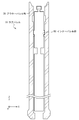
- FIG. 2A is a partial cross-sectional view showing a configuration example of a core barrel provided at a distal end portion of a drill string used in a wireline recovery method.
- FIG. 2B is a cross-sectional view illustrating a configuration example of an outer barrel portion of the core barrel illustrated in FIG. 2A.
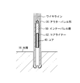
- FIG. 2C is a cross-sectional view showing a more detailed configuration example of the inner barrel portion of the core barrel shown in FIG. 2A.
- FIG. 3A is a diagram showing a first stage of an example of a core collection technique using the core barrel shown in FIGS. 2A to 2C.
- FIG. 1 is a diagram illustrating a configuration example of a coring system (a kind of bottom hole assembly) for excavating the seabed.
- FIG. 2A is a partial cross-sectional view showing a configuration example of a
- FIG. 3B is a diagram illustrating a second stage of an example of a core collection technique.
- FIG. 3C is a diagram illustrating a third stage of an example of a core collection technique.
- FIG. 4 is a diagram showing an example of a core collection technique in which a casing pipe is combined with the drill string shown in FIGS. 2A to 2C.
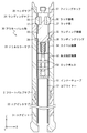
- FIG. 5A is a cross-sectional view illustrating a configuration example of a core barrel using a float valve sub according to an embodiment.
- FIG. 5B is a partial cross-sectional view showing a connection relationship of the float valve sub according to the embodiment with another sub.
- FIG. 6 is a cross-sectional view illustrating a configuration example of the outer barrel assembly in the float valve sub according to the embodiment.
- FIG. 7A is a diagram illustrating a configuration example of a float valve assembly according to an embodiment with a flapper lid in a first position.
- FIG. 7B is a diagram illustrating a configuration example of the float valve assembly according to an embodiment with a flapper lid in a second position.
- FIG. 7C is a side view of the float valve assembly in the state shown in FIG. 7B.
- FIG. 8A shows the flapper lid of the float valve assembly shown in FIGS. 7A and 7B.
- 8B is a cross-sectional view of the flapper lid shown in FIG. 8A, taken along section line AA.
- 8C is a cross-sectional view of the flapper lid shown in FIG. 8A, taken along section line BB.
- FIG. 8A shows the flapper lid of the float valve assembly shown in FIGS. 7A and 7B.
- 8B is a cross-sectional view of the flapper lid shown in FIG. 8A, taken along section line AA.
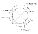
- FIG. 9 is a diagram illustrating a geometric relationship between the inner diameter of the annular recess and the outer diameter of the float valve first opening according to one embodiment.
- FIG. 10 is a diagram illustrating a configuration example of a coring system using a riser excavation system.
- FIG. 1 is a diagram illustrating a configuration example of a coring system for excavating the seabed.
- the coring system is a kind of the bottom hole assembly 1.
- a drilling rig 12 is prepared on the sea surface 14 directly above the seabed 15 to be drilled. It is desirable that the excavation rig 12 keeps its position directly above the excavation position by using a GPS (Global Positioning System) satellite 18 or the like.
- the drilling rig 12 repeats the process of adding the drill string 11 and lowering it to the sea 13.
- the drilling rig 12 controls the drillstring 11 to collect a core as a formation sample from the formation 16 of the seabed 15. *
- the distance from the sea surface 14 to the sea floor 15 may reach several thousand meters. Even in such a case, if the entire drill string 11 is moved up and down every time one core is collected, the working efficiency is poor. . Therefore, there is a technique in which after the drilling by the drill string 11 is started, the core is continuously collected in the drilling rig 12 by using the inner barrel portion inserted inside the outer barrel portion of the drill string without performing the lifting pipe.
- One such technique is a wireline collection method. *
- the coring system shown in FIG. 1 can be used not only for seabed excavation but also for geological excavation on land. *
- FIG. 2A is a cross-sectional view showing a configuration example of the core barrel 10 provided at the distal end portion of the drill string 11 used in the wireline recovery method.
- the core barrel 10 shown in FIG. 2A has a two-layer structure, and has an outer barrel portion 30 on the outer side and an inner barrel portion 50 on the inner side.
- the outer barrel portion 30 has a cylindrical shape, and the inner barrel portion 50 is movable in the longitudinal direction of the core barrel 10 ( ⁇ Z direction of coordinates shown in FIG. 2A). *
- FIG. 2A a cross-sectional view of the outer barrel portion 30 is shown, and a side view of the inner barrel portion 50 is schematically shown.
- the outer barrel portion 30 is provided at the distal end of the drill string 11. *
- FIG. 2B is a cross-sectional view illustrating a configuration example of the outer barrel portion 30 in the core barrel 10 illustrated in FIG. 2A.
- the outer barrel portion 30 shown in FIG. 2B includes a core bit 31, a near bit sub 32, a drill collar sub 33, a landing sub 34, a head sub 35, a landing ring 36, and a latch portion 37.
- the core bit 31 is provided at the distal end of the outer barrel portion 30.
- a near bit sub 32 is connected to the upper end of the core bit 31.
- a drill collar sub 33 is connected to the upper end portion of the near bit sub 32.
- a landing sub 34 is connected to the upper end of the drill collar sub 33.
- a head sub 35 is connected to an upper end portion of the landing sub 34.
- the landing ring 36 is provided in the vicinity of the opening on the upper end side of the inner wall of the drill collar sub 33.
- the latch portion 37 includes a space provided by boring the inner wall of the landing sub 34.
- FIG. 2C is a diagram showing a configuration example of the inner barrel portion 50 in more detail in the core barrel 10 shown in FIG. 2A.
- 2C has an inner tube 51, a core liner 52, a length adjusting mechanism 53, a swivel mechanism 54, a landing mechanism 55, a latch mechanism 56, and a fishing neck 57.
- the length adjusting mechanism 53 has a lock bolt 58. *
- the inner tube 51 is provided at the distal end of the inner barrel portion 50.
- a core liner 52 is provided inside the inner tube 51.
- a length adjusting mechanism 53 is provided on the upper end side of the inner tube 51.
- a swivel mechanism 54 is provided on the upper end side of the length adjusting mechanism 53.
- a landing mechanism 55 is provided on the upper end side of the swivel mechanism 54.
- a latch mechanism 56 is provided on the upper end portion side of the landing mechanism 55.
- a fishing neck 57 is provided on the upper end side of the latch mechanism 56. *
- the fishing neck 57 removably connects the inner barrel portion 50 to a wire line extending from the excavation rig 12.
- the excavation rig 12 controls the wire line to attach and detach the wire line and the fishing neck 57.
- the latch mechanism 56 fixes the inner barrel portion 50 to the outer barrel portion 30 by fitting into the latch portion 37.
- the rotational movement of the outer barrel portion 30 is transmitted to the inner barrel portion 50.
- the latch mechanism 56 is released from the engagement with the latch portion 37 when the inner barrel portion 50 is recovered by the excavation rig 12 via the wire line.
- the landing mechanism 55 adjusts the positional relationship between the inner barrel portion 50 and the outer barrel portion 30 in the longitudinal direction of the drill string 11.
- the outer diameter of the landing mechanism 55 is larger than the inner diameter of the landing ring 36.
- the lower surface of the landing mechanism 55 is placed on the upper surface of the landing ring 36, whereby the inner barrel portion 50 and the outer barrel portion 30. May be determined.
- the swivel mechanism 54 rotates the core liner 52 disposed on the distal side of the swivel mechanism as the outer barrel portion 30 rotates so that the core being collected is not twisted with respect to the excavated formation. It is provided for the purpose of preventing it.
- the swivel mechanism 54 includes an outer portion connected to the upper end side of the inner barrel portion 50, an inner portion connected to the lower end side, and a bearing provided between the outer portion and the inner portion. And have. Due to the presence of the swivel mechanism 54, the rotational movement of the outer barrel portion 30 is not transmitted to the components disposed below the swivel mechanism 54 in the inner barrel portion 50. *
- the length adjusting mechanism 53 is provided to adjust the overall length of the inner barrel portion 50.
- the length adjusting mechanism 53 includes an inner portion connected to the upper end side of the inner barrel portion 50, an outer portion connected to the lower end side, and a lock bolt 58 connecting the inner portion and the outer portion.
- Each of the inner part and the outer part has a plurality of holes through which the lock bolts 58 are passed.
- the length of the inner barrel part 50 can be adjusted by appropriately selecting a hole through which the lock bolt 58 is passed. *
- the inner tube 51 supports the core liner 52 inside thereof.
- the core liner 52 stores the core to be collected.
- the inner tube 51 preferably has a core catcher and a core lifter (not shown).
- the core catcher and the core lifter separate the core to be collected from the formation.
- the core catcher and the core lifter support the core separated from the formation 16 and prevent its fall. Only one of the core catcher and the core lifter may be used. *
- the outer barrel portion 30 and the inner barrel portion 50 shown in FIGS. 2A to 2C are called rotary core barrels and are used when the formation 16 to be collected is relatively hard. When the formation 16 to be collected is relatively soft, an inner barrel portion 50 having another configuration may be used. *
- FIG. 3A to FIG. 3C are diagrams showing each stage of an example of a core collection method using the drill string 11 shown in FIG. 2A to FIG. 2C. *
- the drill string 11 is extended toward the formation 16 where the sample is to be collected, and the inner barrel portion 50 is lowered toward the outer barrel portion 30 through the inside of the drill string 11.
- the opening of the core bit 31 provided at the distal end of the outer barrel portion 30 and the opening of the core liner 52 provided at the distal end of the inner barrel portion 50 overlap with each other in the excavation progress direction of the drill string 11.
- the drill string traveling direction of the drill string 11 coincides with the longitudinal direction of the drill string 11 and also coincides with the rotation axis direction of the drill string 11. *
- the drill string 11 rotates around the rotation axis and advances through the formation 16. At this time, a part of the formation 16 enters the inside of the core liner 52 through the opening of the core bit 31.
- the excavation rig 12 extends the wire line into the outer barrel portion 30 and connects it to the fishing neck 57 of the inner barrel portion 50, and pulls up the inner barrel portion 50 together with the wire line.
- a part of the formation 16 contained in the core liner 52 is separated from the formation 16 and supported by the core catcher and the core lifter and collected as the core 40 of the formation sample.
- the outer diameter of the casing pipe that can be inserted into the excavation hole 17 is equal to the outer diameter of the core bit 31 excavating the excavation hole 17, so that the excavation hole 17 reinforced with the casing pipe can be further excavated.
- the core bit 31 having a smaller outer diameter is required.
- the excavation hole 17 dug by the core bit 31 having a smaller outer diameter is reinforced by another thinner casing pipe. By repeating such steps, deeper excavation becomes possible.
- FIG. 4 is a partial cross-sectional view showing an example of a core collection technique in which a casing pipe is combined with the drill string 11 shown in FIGS. 2A to 2C. *
- the cross-sectional view shown in FIG. 4 includes the formation 16, the drill string 11, the first casing pipe 71, the second casing pipe 72, the third casing pipe 73, and the fourth casing pipe 74. *
- the first casing pipe 71 to the fourth casing pipe 74 are cylindrical structures having different thicknesses and lengths.
- the outer diameter of the first casing pipe 71 is the largest, the outer diameter of the second casing pipe 72 is the next largest, the outer diameter of the third casing pipe 73 is the next largest, and the outer diameter of the fourth casing pipe 74 is The thinnest.
- the first casing pipe 71 is the shortest, the second casing pipe 72 is the next shortest, the third casing pipe 73 is the next shortest, and the fourth casing pipe 74 is the longest. *
- the first casing pipe 71 to the fourth casing pipe 74 are arranged concentrically when viewed from directly above the excavation hole 17 and are buried in the formation 16.
- the upper end portion may be located on the surface of the formation 16.
- the depth at which excavation is possible is improved, while the thickness (outer diameter) of the usable core bit 31 is gradually reduced. Therefore, the outer diameter and inner diameter of the usable drill string 11 are also gradually reduced.
- This embodiment proposes the structure which can suppress the reduction
- FIG. 5A is a cross-sectional view illustrating a configuration example of the outer barrel portion 30 using the float valve sub according to the present embodiment.
- the outer barrel portion 30 shown in FIG. 5A is equivalent to the outer barrel portion 30 shown in FIGS. 2A to 2C with the addition of the float valve sub 2 according to the present embodiment.
- the float valve sub 2 is disposed between the drill collar sub 33 and the near bit sub 32, and the inner tube 51 passes through the inside thereof. *
- the float valve sub 2 according to the present embodiment may be disposed at another location of the outer barrel portion 30.
- the float valve sub 2 according to the present embodiment may be disposed between the core bit 31 and the near bit sub 32.
- the float valve sub 2 may be disposed between the landing sub 34 and the drill collar sub 33.
- each sub including the float valve sub 2 has as high rotational symmetry as possible with respect to the rotation axis of the drill string 11.
- each sub desirably has as high rotational symmetry as possible in order to realize the molding and processing more easily and with higher accuracy.
- rotating bodies such as circles, disks, cylinders, and cylinders appear in various parts in the following description. However, these rotating bodies are not limited to geometrically strict circles, disks, cylinders, cylinders, and the like, but are realistic enough to prevent stable rotation of the drill string 1 and assembly of each sub. Variations within the range may be included.
- FIG. 5B is a partial cross-sectional view showing the connection relationship of the float valve sub 2 according to the present invention with another sub. *
- the float valve sub 2 shown in FIG. 5B has an outer barrel assembly 100 as an outer cylinder assembly and a float valve assembly 200.
- the float valve assembly 200 is disposed inside the outer barrel assembly 100.
- FIG. 5B shows a cross-sectional view of the outer barrel assembly 100. *
- the float valve sub 2 shown in FIG. 5B has an upper sub 300 connected to the upper end side thereof. Further, the float valve sub 2 shown in FIG. 5B has a lower sub 500 connected to the lower end side thereof.
- a taper screw having excellent water tightness.
- FIG. 6 is a cross-sectional view showing a configuration example of the outer barrel assembly 100 in the float valve sub 2 according to the present embodiment. *
- the outer barrel assembly 100 as the outer cylinder assembly is preferably formed by processing a single member from the viewpoint of strength and water tightness.
- the outer barrel assembly 100 includes an outer barrel first part 110, an outer barrel second part 120, and an outer barrel intermediate part 130. *
- the outer barrel first portion 110 is the proximal end of the outer barrel assembly 100.
- the outer barrel second portion 120 is the distal end of the outer barrel assembly 100.
- the outer barrel intermediate portion 130 is disposed between the outer barrel first portion 110 and the outer barrel second portion 120.
- the outer barrel first portion 110 includes an outer barrel first connecting portion 111 and an outer barrel first receiving portion 112. A space inside the outer barrel first portion 110 is referred to as an outer barrel first opening 101. *
- the outer barrel first connection part 111 is connected to the lower end side connection part of the upper sub 300.
- a tapered female screw is formed inside the outer barrel first connecting portion 111, and this is fitted with a tapered male screw formed outside the lower end side connecting portion of the upper sub 300.
- the inner peripheral surface of the outer barrel first receiving portion 112 has a shape complementary to the upper end portion (the outer peripheral surface of the upper end portion) of the float valve assembly 200, and receives the upper end portion of the float valve assembly 200. And support.
- the outer barrel first receiving portion 112 has a shape that allows the entire float valve assembly 200 to pass to the outer barrel second receiving portion 122 when the float valve assembly 200 is attached to the outer barrel assembly 100.
- the outer barrel second portion 120 includes an outer barrel second connecting portion 121 and an outer barrel second receiving portion 122.
- the space inside the outer barrel second portion 120 is referred to as the outer barrel second opening 102. *
- the outer barrel second connection part 121 is connected to the upper end side connection part of the lower sub 500.
- a tapered male screw is formed on the outer side of the outer barrel second connecting portion 121, and this is fitted with the tapered female screw formed on the inner side of the upper end side connecting portion of the lower sub 500.
- the inner peripheral surface of the outer barrel second receiving portion 122 has a shape complementary to the lower end portion (outer peripheral surface of the lower end portion) of the float valve assembly 200 on the inner peripheral surface thereof. Receive and support the lower end of the assembly 200.
- the outer barrel second receiving portion 122 has such a shape that the float valve assembly 200 does not pass and does not fall to the lower sub-side of the outer barrel assembly 100.
- the minimum inner diameter DO2 of the outer barrel second portion 120 is smaller than the minimum inner diameter DO1 of the outer barrel first portion 110.
- the minimum inner diameter DO2 is smaller than the maximum outer diameter of the float valve assembly 200 that allows at least the inner tube 51 to penetrate the inside. *
- the outer barrel first opening 101 is connected to the upper side of this space.
- the outer barrel second opening 102 is connected to the lower side of this space.
- the annular recess 103 may be formed by a method such as boring the inner wall of the outer barrel assembly 100.
- the annular recess 103 is provided to receive a flapper lid protruding from the cylindrical portion of the float valve assembly 200.
- the inner diameter DO3 of the annular recess 103 is larger than the minimum inner diameter DO1 of the outer barrel first portion 110.
- the inner diameter at the boundary with the outer barrel first portion 110 on the upper side of the outer barrel intermediate portion 130 is equal to the inner diameter D01 of the outer barrel first receiving portion 112.
- the inner diameter DO3 of the annular recess 103 of the outer barrel intermediate portion 130 is larger than the inner diameter DO1 of the outer barrel first receiving portion 112.
- the inner diameter at the boundary with the outer barrel second portion 120 on the lower side of the outer barrel intermediate portion 130 is equal to the inner diameter D01 of the outer barrel second receiving portion 122.
- the inner diameter DO3 of the annular recess 103 of the outer barrel intermediate portion 130 is larger than the inner diameter DO1 of the outer barrel second receiving portion 122.
- the inner diameter at the boundary between the outer barrel intermediate portion 130 and the outer barrel second portion 120 is the same as the inner diameter D01 of the outer barrel first receiving portion 112, but the former is the latter. It is also possible to make it smaller.
- the minimum wall thickness of the drill pipe of the drill string 11 is expressed as Tmin.
- the drill pipe is an outer wall portion of the drill string 11 on the side of the drilling rig 12 from the rotary core barrel, and has a function of transmitting rotational motion from the drilling rig 12 to the rotary core barrel.
- the strength required for the outer barrel assembly 100 that is a part of the structure constituting the drill string 11 can be any of the outer barrel assemblies 100. Even in the portion, the thickness is guaranteed if the thickness is equal to or greater than the minimum thickness Tmin.
- the thickness T is preferably equal to or greater than the minimum thickness Tmin.
- the material of the outer barrel assembly 100 may be changed to a material having higher strength.
- FIG. 7A is a diagram illustrating a state in which the flapper lid 230 is in the first position in one configuration example of the float valve assembly 200 according to the present embodiment.
- FIG. 7B is a diagram showing a state in which the flapper lid 230 is in the second position in one configuration example of the float valve assembly 200 according to the present embodiment.
- FIG. 7C is a side view of the float valve assembly 200 in the state shown in FIG. 7B. 7A and 7B, a part of the outer wall is shown as a cross-sectional view in order to explain the inside of the float valve assembly 200. *
- FIG. 8A shows the flapper lid 230 of the float valve assembly 200 shown in FIGS. 7A-7C.
- FIG. 8B is a cross-sectional view of the flapper lid 230 shown in FIG. 8A along the cross-sectional line AA.
- FIG. 8C is a cross-sectional view of the flapper lid 230 shown in FIG. 8A along the cross-sectional line BB. *
- the float valve assembly 200 shown in FIGS. 7A to 7C includes a float valve body 210, a flapper lid 230, a hinge 240, a biasing member 250, a sealing member 224, a retainer 225, and a fixing sealing member. 211 and 212. *
- the float valve body 210 shown in FIGS. 7A to 7C includes an upper float valve first end portion 201, a lower float valve second end portion 202, and a float valve intermediate portion 203.
- the float valve intermediate portion 203 is disposed between the float valve first end portion 201 and the float valve second end portion 202.
- the float valve body 210 may be formed by assembling the float valve first end portion 201, the float valve second end portion 202, and the float valve intermediate portion 203 that are separately formed.
- the float valve first end portion 201 includes a body side hinge support portion 213, a body side biasing member support portion 214, and a float valve first opening portion 221.
- the float valve second end 202 has a float valve second opening 222.
- the float valve intermediate portion 203 has a side opening 223. *
- the flapper lid 230 shown in FIGS. 7A to 7C and FIGS. 8A to 8C has a flat surface portion 231, an inner tube guide 232, a side end portion 233, a lid side hinge support portion 234, and a lid side biasing member support. Part 235. *
- FIGS. 7A to 7C and FIGS. 8A to 8C The connection relationships of the components shown in FIGS. 7A to 7C and FIGS. 8A to 8C will be described. *
- the float valve first end 201 has a cylindrical shape.
- the retainer 225 also has a cylindrical shape, and is fitted inside the float valve first end 201.
- the sealing member 224 is made of an elastic material and has an annular shape, and is disposed between the float valve first end 201 and the retainer 225. However, the sealing sealing member 224 has an annular end surface exposed to the space inside the float valve body 210.
- the assembly of the float valve first end portion 201, the retainer 225, and the sealing member 224 for sealing also has a cylindrical shape, and the space inside thereof is called a float valve first opening 221. At this time, the sealing member 224 for sealing is arranged so that the exposed portion surrounds the lower opening surface of the float valve first opening 221.
- the float valve first opening 221 has a size and shape that allows the inner tube 51 to pass through the inside thereof.
- the inner diameter of the float valve first opening 221 is DF2.
- DF2 is strictly the inner diameter of the retainer 225.
- the fixing sealing members 211 and 212 each have an annular shape and are arranged so as to surround the outer periphery of the float valve first end 201.
- the float valve first end portion 201 may have a groove on the outer periphery thereof in order to position the fixing sealing members 211 and 212.
- the fixing sealing members 211 and 212 can be realized by a configuration different from the above.
- a groove may be provided in the surface of the float valve first end 201 that contacts the upper sub 300, and the sealing member 224 for sealing may be disposed in this groove.
- the float valve second end portion 202 has a cylindrical shape, and a space inside the float valve second end portion 202 is referred to as a float valve second opening 222.
- the float valve second opening 222 has a size and shape that allows the inner tube 51 to pass through the inside thereof.
- the inner diameter of the float valve second opening 222 is the same as DF2 as the inner diameter of the float valve first opening 221.
- the inner diameter of the float valve first opening 221 and the inner diameter of the float valve second opening 222 may not necessarily be the same as long as the inner tube 51 can penetrate. *
- the float valve intermediate portion 203 has a cylindrical shape, and a float valve first end portion 201 is connected to an upper end portion thereof, and a float valve second end portion 202 is connected to a lower end portion thereof. Is connected.
- the space inside the float valve intermediate portion 203 is connected to the float valve first opening 221 on the upper side, and connected to the float valve second opening 222 on the lower side.
- Side opening 223 is provided on the side surface of the float valve middle part.
- the side opening 223 is wide enough to allow the flapper lid 230 to pass when moving between the first position and the second position.
- the float valve first end 201 and the flapper lid 230 are connected via a hinge 240.
- the hinge 240 has a cylindrical shape and penetrates the body side hinge support portion 213 and the lid side hinge support portion 234 in its longitudinal direction.
- it is desirable that the hinge 24 is fixed to the body side hinge support portion 213 or the lid side hinge support portion 234 by screwing or the like so that the hinge 24 does not fall off.
- the flapper lid 230 can move between a first position and a second position by rotating around a rotation axis set in the longitudinal direction of the hinge 240.
- the first position is a position where the flapper lid 230 is in close contact with the sealing member 224 and closes the float valve first opening 221 (flow path).
- the second position is a retracted position where the flapper lid 230 releases the flow path of the float valve first opening 221 and does not interfere with the inner tube 51 passing through the float valve assembly.
- the second position is, for example, a position where the entire flapper lid 230 does not overlap the float valve first opening 221 (or the float valve second opening 222) when viewed in the longitudinal direction of the outer barrel assembly 100. *
- the urging member 250 urges the flapper lid 230 toward the first position.
- the urging member 250 is a coiled torsion spring, and the coil portion is disposed around the hinge 240, one end of which is in contact with the body side urging member support 214, and the other end. Contacts the lid-side biasing member support 235.
- a load is applied from the biasing member 250 to the surrounding float valve body 210 so that one end of the biasing member 250 does not come off. Indented in the direction.
- a load is applied from the biasing member 250 to the surrounding flapper lid 230 so that the other end of the biasing member 250 does not come off. Indented in the direction.
- the float valve assembly 200 When the float valve assembly 200 is mounted inside the outer barrel assembly 100, the float valve first end 201 is received and fixed by the outer barrel first receiving portion 112, and the float valve second end 202 is fixed to the outer barrel assembly 100. It is received and supported by the barrel second receiving portion 122. At this time, the float valve second opening 222 is connected to the outer barrel second opening 102.
- the fixing sealing members 211 and 212 seal the float valve first end portion 201 and the outer barrel first receiving portion 112 in a liquid-tight manner.
- DF1 is substantially equal to the minimum inner diameter DO1 of the outer barrel first portion 110, but is preferably equal to or less than DO1.
- the float valve first opening 221 is connected to the lower opening of the upper sub 300.
- the float valve assembly 200 is fixed on the upper side by connection with the upper sub 300.
- the inner tube 51 can pass through the upper sub 300, the float valve first opening 221, the float valve second opening 222, and the outer barrel second opening 102.
- the flapper lid 230 has a flat plane portion 231 at least in the peripheral region of the main surface thereof.
- the flat surface portion 231 contacts the sealing member 224 when the flapper lid 230 moves to the first position.
- the flapper lid 230 closes the flow path of the float valve first opening 221.
- the flapper lid 230 In this state, even if a fluid flows into the drill string 1 from a portion below the float valve sub 2, it does not leak to the upper side of the float valve sub 2 and can prevent a violence.
- the inventor conducted an experiment in which water pressure was applied from the float valve second opening side in the first state of the float valve sub 2 according to the present embodiment.
- the float valve sub 2 having an inner diameter of 98.5 mm was about 20 It was confirmed that durability up to megapascal pressure was obtained.
- This experimental result is merely an example, and does not limit the scope of rights of the present invention.
- the flapper lid 230 moves to the second position, a part of the flapper lid 230 protrudes outside the float valve body 210 through the side opening 223.
- This protruding portion is referred to as a side end portion 233 for ease of explanation.
- the side end 233 has a size and a shape that can be accommodated in the annular recess 103 of the outer barrel assembly 100.
- the inner tube guide 232 included in the flapper lid 230 has a curved surface similar to the outer peripheral surface of the float valve second opening 222 (the inner peripheral surface of the float valve second end 202). ing. Since the inner peripheral surface of the float valve second end portion 202 has a curved surface that is complementary to the side surface of the inner tube 51 that is a cylindrical member, the curved surface of the inner tube guide 232 is also connected to the side surface of the inner tube 51. Complementary shape. Due to this curved surface, the inner tube guide 232 allows the inner tube 51 to be more stably inserted and removed when the flapper lid 230 is in the second position. *
- FIG. 9 is a diagram showing a geometric relationship between the inner diameter DO3 of the annular recess 103 according to the present embodiment and the diameter DF2 of the float valve first opening 221.
- the size thereof needs to be at least equal to or larger than the diameter DF2 of the float valve first opening portion 221.
- a square diagonal line in which the inner diameter DO3 of the annular recess 103 circumscribes a circle having a diameter DF2 is used. Need longer.
- the length DO3 needs to be not less than the square root of 2 times the length DF2.
- the square of the length DO3 needs to be at least twice the square of the length DF2.
- the minimum value of the length DO3 is obtained as described above.
- the maximum value of the length DO3 depends on the strength required for the float valve sub 2 as described above. That is, when the minimum value of the thickness of the side wall portion of the outer barrel assembly 100 that satisfies the required strength is set as Tmin1 and the outer diameter of the outer barrel assembly 100 is set as DO4, the maximum value of the length DO3 is set to be between DO4 and Tmin1. It is equal to the difference with 2 times. Therefore, the numerical limitation related to the length DO3 can be expressed by the following mathematical formula. DO4-2 ⁇ Tmin1 ⁇ DO3> DF2 ⁇ ⁇ 2
- the bare hole without casing satisfies the condition of “geological pressure ⁇ mud water pressure ⁇ geological fracture pressure”, but the geological pressure rises as it digs, so it is necessary to increase the mud pressure accordingly. There is. If you dig too much without the casing, the muddy water pressure will exceed the formation destruction pressure in the upper part of the bare hole, and the muddy water will destroy the formation and the formation will collapse.
- the riser drilling system prevents collapse by casing before it happens. As a result, in the riser excavation system, the depth at which excavation is possible is dramatically improved compared to a so-called riserless excavation system that does not use such a technique. *
- the muddy water used in the riser drilling system requires appropriate adjustments physically and chemically.
- the muddy water adjusted in this way pumps up the mud generated by excavating the formation 16 and the surrounding seawater to the drilling rig 12 by the riser pipe, and adjusts the characteristics thereof by the mud adjusting device mounted on the drilling rig 12. Is generated.
- the adjusted muddy water is sent to the bottom of the drilling hole 17 through the inside of the drill string 11.
- FIG. 10 is a diagram illustrating a configuration example of a coring system using a riser excavation system.
- FIG. 10 is equivalent to a coring system using the riser-less excavation system shown in FIG. 1 to which a riser pipe 19 and an ejection prevention device 20 are added.
- illustration is abbreviate
- the riser pipe 19 is provided around the drill string 11 and extends from the seabed 15 to the drilling rig 12.
- the seabed 15 is provided with an ejection preventing device 20 that connects the excavation hole 17 and the riser pipe 19.
- the float valve sub 2 according to the present invention can be easily applied to the riser excavation system.
- the shape of the annular recess 103 is a rotating body centered on the rotation axis of the drill string 11 has been described so far.
- This description considers the possibility that the float valve assembly 200 rotates with respect to the outer barrel assembly 100 when the annular recess 103 is formed by a lathe process or when the upper sub 300 is attached or detached.
- the annular recess 103 is not necessarily required to have the shape of a rotating body as long as the function of receiving the flapper lid 230 protruding from the cylindrical portion of the float valve assembly 200 can be realized. Further, it may be a concave portion having other shapes such as a cut portion and a cut portion.
Landscapes
- Life Sciences & Earth Sciences (AREA)
- Engineering & Computer Science (AREA)
- Geology (AREA)
- Mining & Mineral Resources (AREA)
- Physics & Mathematics (AREA)
- Environmental & Geological Engineering (AREA)
- Fluid Mechanics (AREA)
- General Life Sciences & Earth Sciences (AREA)
- Geochemistry & Mineralogy (AREA)
- Valve Housings (AREA)
- Earth Drilling (AREA)
Abstract
Un évidement qui accueille un couvercle de soupape à flotteur, tel qu'une extension, une partie broyée, une partie découpée, ou similaire, est formé à l'intérieur d'un ensemble cylindre externe d'un train de tiges de forage. Ainsi, lorsque le train de tiges de forage est pourvu d'une soupape à flotteur, le diamètre interne du train de tiges de forage peut être élargi et une carotte de diamètre supérieur peut être collectée à l'aide d'un train de tiges de forage plus fin.
Priority Applications (2)
| Application Number | Priority Date | Filing Date | Title |
|---|---|---|---|
| US15/746,221 US10767446B2 (en) | 2015-07-21 | 2016-07-21 | Float valve sub |
| EP16827823.2A EP3327248A4 (fr) | 2015-07-21 | 2016-07-21 | Raccord de soupape à flotteur |
Applications Claiming Priority (2)
| Application Number | Priority Date | Filing Date | Title |
|---|---|---|---|
| JP2015144300A JP6551001B2 (ja) | 2015-07-21 | 2015-07-21 | フロートバルブサブ |
| JP2015-144300 | 2015-07-21 |
Publications (1)
| Publication Number | Publication Date |
|---|---|
| WO2017014263A1 true WO2017014263A1 (fr) | 2017-01-26 |
Family
ID=57835119
Family Applications (1)
| Application Number | Title | Priority Date | Filing Date |
|---|---|---|---|
| PCT/JP2016/071390 Ceased WO2017014263A1 (fr) | 2015-07-21 | 2016-07-21 | Raccord de soupape à flotteur |
Country Status (4)
| Country | Link |
|---|---|
| US (1) | US10767446B2 (fr) |
| EP (1) | EP3327248A4 (fr) |
| JP (1) | JP6551001B2 (fr) |
| WO (1) | WO2017014263A1 (fr) |
Families Citing this family (18)
| Publication number | Priority date | Publication date | Assignee | Title |
|---|---|---|---|---|
| CA3045409A1 (fr) * | 2016-12-05 | 2018-06-14 | Flexidrill Limited | Appareil de carottage |
| JP6927484B2 (ja) | 2017-02-17 | 2021-09-01 | 国立研究開発法人海洋研究開発機構 | 海底掘削サポートシステム |
| GB2581880A (en) | 2017-11-20 | 2020-09-02 | Halliburton Energy Services Inc | Full bore buoyancy assisted casing system |
| WO2020117229A1 (fr) | 2018-12-05 | 2020-06-11 | Halliburton Energy Services, Inc. | Appareil de fond de trou |
| WO2020131076A1 (fr) | 2018-12-20 | 2020-06-25 | Halliburtion Energy Services, Inc. | Outil d'aide à la flottabilité |
| WO2020131104A1 (fr) | 2018-12-21 | 2020-06-25 | Halliburton Energy Services, Inc. | Outil d'assistance à la flottabilité |
| US11603736B2 (en) | 2019-04-15 | 2023-03-14 | Halliburton Energy Services, Inc. | Buoyancy assist tool with degradable nose |
| WO2020214154A1 (fr) | 2019-04-16 | 2020-10-22 | Halliburton Energy Services, Inc. | Appareil de fond de trou avec bouchons dégradables |
| US11255155B2 (en) | 2019-05-09 | 2022-02-22 | Halliburton Energy Services, Inc. | Downhole apparatus with removable plugs |
| US11499395B2 (en) | 2019-08-26 | 2022-11-15 | Halliburton Energy Services, Inc. | Flapper disk for buoyancy assisted casing equipment |
| US11105166B2 (en) | 2019-08-27 | 2021-08-31 | Halliburton Energy Services, Inc. | Buoyancy assist tool with floating piston |
| US11072990B2 (en) | 2019-10-25 | 2021-07-27 | Halliburton Energy Services, Inc. | Buoyancy assist tool with overlapping membranes |
| US10995583B1 (en) | 2019-10-31 | 2021-05-04 | Halliburton Energy Services, Inc. | Buoyancy assist tool with debris barrier |
| US10989013B1 (en) | 2019-11-20 | 2021-04-27 | Halliburton Energy Services, Inc. | Buoyancy assist tool with center diaphragm debris barrier |
| US11230905B2 (en) | 2019-12-03 | 2022-01-25 | Halliburton Energy Services, Inc. | Buoyancy assist tool with waffle debris barrier |
| US11142994B2 (en) | 2020-02-19 | 2021-10-12 | Halliburton Energy Services, Inc. | Buoyancy assist tool with annular cavity and piston |
| US11359454B2 (en) | 2020-06-02 | 2022-06-14 | Halliburton Energy Services, Inc. | Buoyancy assist tool with annular cavity and piston |
| US11753904B2 (en) | 2021-05-10 | 2023-09-12 | Baker Hughes Oilfield Operations Llc | Valve having a modular activation system |
Citations (3)
| Publication number | Priority date | Publication date | Assignee | Title |
|---|---|---|---|---|
| US3318387A (en) * | 1964-09-28 | 1967-05-09 | Chevron Res | Drilling method and apparatus |
| US4457376A (en) * | 1982-05-17 | 1984-07-03 | Baker Oil Tools, Inc. | Flapper type safety valve for subterranean wells |
| US6152232A (en) * | 1998-09-08 | 2000-11-28 | Halliburton Energy Services, Inc. | Underbalanced well completion |
Family Cites Families (8)
| Publication number | Priority date | Publication date | Assignee | Title |
|---|---|---|---|---|
| US2162578A (en) | 1937-05-27 | 1939-06-13 | Marcus L Hacker | Core barrel operated float valve |
| US3058534A (en) | 1958-04-29 | 1962-10-16 | Baker Oil Tools Inc | Drill pipe float valves |
| NL103683C (fr) | 1959-05-20 | |||
| US3066693A (en) | 1960-02-18 | 1962-12-04 | Jr Julian S Taylor | Float valve for drill pipe and the like |
| US3446237A (en) | 1967-04-03 | 1969-05-27 | William L Haley | Drill pipe float valve |
| US4691775A (en) * | 1986-03-25 | 1987-09-08 | Dresser Industries, Inc. | Isolation valve with frangible flapper element |
| US8607876B2 (en) | 2011-02-16 | 2013-12-17 | Thrubit, B.V. | Flapper valve |
| US10151173B2 (en) | 2012-09-13 | 2018-12-11 | Switchfloat Holdings Limited | Float valve hold open devices and methods therefor |
-
2015
- 2015-07-21 JP JP2015144300A patent/JP6551001B2/ja not_active Expired - Fee Related
-
2016
- 2016-07-21 WO PCT/JP2016/071390 patent/WO2017014263A1/fr not_active Ceased
- 2016-07-21 EP EP16827823.2A patent/EP3327248A4/fr not_active Withdrawn
- 2016-07-21 US US15/746,221 patent/US10767446B2/en not_active Expired - Fee Related
Patent Citations (3)
| Publication number | Priority date | Publication date | Assignee | Title |
|---|---|---|---|---|
| US3318387A (en) * | 1964-09-28 | 1967-05-09 | Chevron Res | Drilling method and apparatus |
| US4457376A (en) * | 1982-05-17 | 1984-07-03 | Baker Oil Tools, Inc. | Flapper type safety valve for subterranean wells |
| US6152232A (en) * | 1998-09-08 | 2000-11-28 | Halliburton Energy Services, Inc. | Underbalanced well completion |
Non-Patent Citations (1)
| Title |
|---|
| See also references of EP3327248A4 * |
Also Published As
| Publication number | Publication date |
|---|---|
| EP3327248A1 (fr) | 2018-05-30 |
| JP2017025553A (ja) | 2017-02-02 |
| US20180209245A1 (en) | 2018-07-26 |
| US10767446B2 (en) | 2020-09-08 |
| EP3327248A4 (fr) | 2019-03-27 |
| JP6551001B2 (ja) | 2019-07-31 |
Similar Documents
| Publication | Publication Date | Title |
|---|---|---|
| JP6551001B2 (ja) | フロートバルブサブ | |
| US9080399B2 (en) | Earth-boring tools including retractable pads, cartridges including retractable pads for such tools, and related methods | |
| US10125559B2 (en) | Core jam indicator for coring tools and coring tools including such core jam indicators | |
| US10253591B2 (en) | Downhole string for drilling through a low pressure zone | |
| US20110000665A1 (en) | Hydraulically Locking Stabilizer | |
| CN106837202B (zh) | 用于负压取心的地质勘探双层钻杆及其配套钻具 | |
| US9976413B2 (en) | Pressure locking device for downhole tools | |
| US11788369B2 (en) | Method and apparatus to recover cores from downhole environments | |
| US11624252B1 (en) | Adjustable mill | |
| US8869915B2 (en) | Systems and methods for sonic subsurface material removal | |
| US8783649B2 (en) | Sleeve valve with permanent end position | |
| US10975644B2 (en) | Inner barrel assembly for recovery of reservoir fluids from a core sample | |
| US12215557B2 (en) | Method and apparatus to recover cores from downhole environments | |
| US11913297B1 (en) | Method and apparatus for deploying and cementing liners across challenging well profiles | |
| US10871051B2 (en) | System and method for drilling a wellbore portion in a subterranean formation | |
| US11982159B2 (en) | Wellbore protector ram | |
| WO2023193167A1 (fr) | Mécanisme de transmission d'impact pour un outil de forage à percussion rotatif | |
| US11585207B2 (en) | Advanced rapid logging system | |
| US11725475B2 (en) | Drill pipe conveyed permanent bridge plug with integral casing scraper | |
| US20180216418A1 (en) | Adjustable Hydraulic Coupling For Drilling Tools And Related Methods | |
| US20220268115A1 (en) | Reamer / guide interchangeable tubular shoe |
Legal Events
| Date | Code | Title | Description |
|---|---|---|---|
| 121 | Ep: the epo has been informed by wipo that ep was designated in this application |
Ref document number: 16827823 Country of ref document: EP Kind code of ref document: A1 |
|
| WWE | Wipo information: entry into national phase |
Ref document number: 15746221 Country of ref document: US |
|
| NENP | Non-entry into the national phase |
Ref country code: DE |
|
| WWE | Wipo information: entry into national phase |
Ref document number: 2016827823 Country of ref document: EP |