WO2017014275A1 - 結束機 - Google Patents
結束機 Download PDFInfo
- Publication number
- WO2017014275A1 WO2017014275A1 PCT/JP2016/071425 JP2016071425W WO2017014275A1 WO 2017014275 A1 WO2017014275 A1 WO 2017014275A1 JP 2016071425 W JP2016071425 W JP 2016071425W WO 2017014275 A1 WO2017014275 A1 WO 2017014275A1
- Authority
- WO
- WIPO (PCT)
- Prior art keywords
- wire
- feed
- reinforcing bar
- displacement
- guide
- Prior art date
- Legal status (The legal status is an assumption and is not a legal conclusion. Google has not performed a legal analysis and makes no representation as to the accuracy of the status listed.)
- Ceased
Links
Images






















Classifications
-
- E—FIXED CONSTRUCTIONS
- E04—BUILDING
- E04G—SCAFFOLDING; FORMS; SHUTTERING; BUILDING IMPLEMENTS OR AIDS, OR THEIR USE; HANDLING BUILDING MATERIALS ON THE SITE; REPAIRING, BREAKING-UP OR OTHER WORK ON EXISTING BUILDINGS
- E04G21/00—Preparing, conveying, or working-up building materials or building elements in situ; Other devices or measures for constructional work
- E04G21/12—Mounting of reinforcing inserts; Prestressing
- E04G21/122—Machines for joining reinforcing bars
-
- B—PERFORMING OPERATIONS; TRANSPORTING
- B21—MECHANICAL METAL-WORKING WITHOUT ESSENTIALLY REMOVING MATERIAL; PUNCHING METAL
- B21F—WORKING OR PROCESSING OF METAL WIRE
- B21F15/00—Connecting wire to wire or other metallic material or objects; Connecting parts by means of wire
- B21F15/02—Connecting wire to wire or other metallic material or objects; Connecting parts by means of wire wire with wire
- B21F15/04—Connecting wire to wire or other metallic material or objects; Connecting parts by means of wire wire with wire without additional connecting elements or material, e.g. by twisting
-
- B—PERFORMING OPERATIONS; TRANSPORTING
- B21—MECHANICAL METAL-WORKING WITHOUT ESSENTIALLY REMOVING MATERIAL; PUNCHING METAL
- B21F—WORKING OR PROCESSING OF METAL WIRE
- B21F15/00—Connecting wire to wire or other metallic material or objects; Connecting parts by means of wire
- B21F15/02—Connecting wire to wire or other metallic material or objects; Connecting parts by means of wire wire with wire
- B21F15/06—Connecting wire to wire or other metallic material or objects; Connecting parts by means of wire wire with wire with additional connecting elements or material
-
- B—PERFORMING OPERATIONS; TRANSPORTING
- B21—MECHANICAL METAL-WORKING WITHOUT ESSENTIALLY REMOVING MATERIAL; PUNCHING METAL
- B21F—WORKING OR PROCESSING OF METAL WIRE
- B21F7/00—Twisting wire; Twisting wire together
-
- B—PERFORMING OPERATIONS; TRANSPORTING
- B25—HAND TOOLS; PORTABLE POWER-DRIVEN TOOLS; MANIPULATORS
- B25B—TOOLS OR BENCH DEVICES NOT OTHERWISE PROVIDED FOR, FOR FASTENING, CONNECTING, DISENGAGING, OR HOLDING
- B25B25/00—Implements for fastening, connecting or tensioning of wire or strip
-
- B—PERFORMING OPERATIONS; TRANSPORTING
- B65—CONVEYING; PACKING; STORING; HANDLING THIN OR FILAMENTARY MATERIAL
- B65B—MACHINES, APPARATUS OR DEVICES FOR, OR METHODS OF, PACKAGING ARTICLES OR MATERIALS; UNPACKING
- B65B13/00—Bundling articles
- B65B13/02—Applying and securing binding material around articles or groups of articles, e.g. using strings, wires, strips, bands or tapes
- B65B13/025—Hand-held tools
-
- B—PERFORMING OPERATIONS; TRANSPORTING
- B65—CONVEYING; PACKING; STORING; HANDLING THIN OR FILAMENTARY MATERIAL
- B65B—MACHINES, APPARATUS OR DEVICES FOR, OR METHODS OF, PACKAGING ARTICLES OR MATERIALS; UNPACKING
- B65B13/00—Bundling articles
- B65B13/02—Applying and securing binding material around articles or groups of articles, e.g. using strings, wires, strips, bands or tapes
- B65B13/04—Applying and securing binding material around articles or groups of articles, e.g. using strings, wires, strips, bands or tapes with means for guiding the binding material around the articles prior to severing from supply
-
- B—PERFORMING OPERATIONS; TRANSPORTING
- B65—CONVEYING; PACKING; STORING; HANDLING THIN OR FILAMENTARY MATERIAL
- B65B—MACHINES, APPARATUS OR DEVICES FOR, OR METHODS OF, PACKAGING ARTICLES OR MATERIALS; UNPACKING
- B65B13/00—Bundling articles
- B65B13/18—Details of, or auxiliary devices used in, bundling machines or bundling tools
- B65B13/24—Securing ends of binding material
- B65B13/28—Securing ends of binding material by twisting
- B65B13/285—Hand tools
-
- E—FIXED CONSTRUCTIONS
- E04—BUILDING
- E04G—SCAFFOLDING; FORMS; SHUTTERING; BUILDING IMPLEMENTS OR AIDS, OR THEIR USE; HANDLING BUILDING MATERIALS ON THE SITE; REPAIRING, BREAKING-UP OR OTHER WORK ON EXISTING BUILDINGS
- E04G21/00—Preparing, conveying, or working-up building materials or building elements in situ; Other devices or measures for constructional work
- E04G21/12—Mounting of reinforcing inserts; Prestressing
- E04G21/122—Machines for joining reinforcing bars
- E04G21/123—Wire twisting tools
Definitions
- the present invention relates to a binding machine that binds bundles such as reinforcing bars with wires.
- a binding machine called a reinforcing bar binding machine for winding a wire around two or more reinforcing bars and twisting the wound wire to bind the two or more reinforcing bars has been proposed.
- a conventional reinforcing bar binding machine has a configuration in which a wire is sent and wound around the reinforcing bar, and then the wire is twisted and bound (for example, see Patent Document 1).
- a wire is sent and wound around the reinforcing bar, and then the wire is twisted and bound
- the wire is sent back in the reverse direction so that the wire is brought into close contact with the reinforcing bar.
- a rebar binding machine that is wound around has been proposed (see, for example, Patent Document 2).
- Any rebar binding machine is configured to feed a wire by pinching the wire with a pair of feeding members.
- the pair of feeding members are close to each other because the wires need to be clamped during wire feeding, but are separated from each other when the wires are removed from the feeding member or when the wires are loaded into the feeding member.
- at least one of the pair of feeding members includes a displacement member for separating from and contacting the other feeding member.
- the displacement member is pressed by a spring or the like so that one feeding member maintains an approaching or separating state with respect to the other feeding member.
- the reinforcing bar binding machine is provided with an operation member for operating the displacement member.
- a displacement member for displacing a pair of feed members and an operation member for operating the displacement members are provided between the feed member and a magazine in which a reel wound with a wire is accommodated. Accordingly, a space for providing the displacement member and the operation member is required between the feed member and the magazine, and the degree of freedom in arranging the magazine is low. Further, since the displacement member and the operation member are present in the wire feed path that passes through the feed member, it becomes an obstacle to the wire loading.
- This invention was made in order to solve such a subject, and it aims at providing the binding machine which reduced the restrictions of arrangement
- the present invention has a receiving means for receiving a wire so that the wire can be drawn out, and a pair of feeding members that sandwich and send the wire, and the wire can be wound around a bundle.
- the apparatus since there is no displacement means for the feed member between the accommodation means and the feed member, the degree of freedom of arrangement of the accommodation means is improved. Thereby, the apparatus can be miniaturized. Further, the wire feed path that passes through the pair of feed members does not have a configuration that obstructs the wire loading, and the wire can be easily loaded.
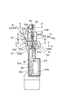
- FIG. 1 is a side view showing an example of the overall configuration of the reinforcing bar binding machine of the present embodiment
- FIG. 2 is a configuration seen from the front side showing an example of the overall configuration of the reinforcing bar binding machine of the present embodiment.
- FIG. 2 schematically shows the internal configuration along the line AA of FIG.
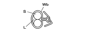
- the reinforcing bar binding machine 1A of the present embodiment binds the reinforcing bars S, which are binding objects, using two or more wires W having a diameter smaller than that of a conventional wire having a large diameter.
- the operation of winding the wire W around the reinforcing bar S, the operation of winding the wire W wound around the reinforcing bar S so as to be in close contact with the reinforcing bar S, and the winding of the reinforcing bar S are performed.
- the rebar S is bound with the wire W by an operation of twisting the wire.
- the wire W is bent in any of the above-described operations.
- the wire W having a diameter smaller than that of the conventional wire the wire can be wound around the reinforcing bar S with less force, and The wire W can be twisted with a small force. Further, by using two or more wires, the binding strength of the reinforcing bars S by the wires W can be ensured. Further, by adopting a configuration in which two or more wires W are sent in parallel, the time required for the operation of winding the wire W can be shortened as compared to the operation of winding the reinforcing bar more than double with one wire.
- winding the wire W around the reinforcing bar S and generically referring to winding the wire W wound around the reinforcing bar S so as to be in close contact with the reinforcing bar S are also described as winding the wire W.
- the wire W may be wound by a bundle other than the reinforcing bar S.
- the wire W a single wire made of a metal that can be plastically deformed or a stranded wire is used.
- the reinforcing bar binding machine 1A includes a magazine 2A that is a storage unit in which wires W are stored, a wire feed unit 3A that sends the wires W stored in the magazine 2A, a wire W that is sent to the wire feed unit 3A, and a wire feed A parallel guide 4A for arranging the wires W fed from the section 3A in parallel is provided. Further, the reinforcing bar binding machine 1A includes a curl guide portion 5A for winding the wire W sent in parallel around the reinforcing bar S and a cutting portion 6A for cutting the wire W wound around the reinforcing bar S. Furthermore, the reinforcing bar binding machine 1A includes a binding part 7A that grips and twists the wire W wound around the reinforcing bar S.
- the magazine 2A is an example of an accommodation unit, and in this example, a reel 20 around which two long wires W are wound so as to be fed out is detachably accommodated.
- the reel 20 includes a cylindrical hub portion 20a around which a wire W can be wound, and a pair of flanges 20b provided at both axial ends of the hub portion 20a.
- the flange 20b has a diameter larger than the diameter of the hub portion 20a, and projects in the radial direction from both axial ends of the hub portion 20a. Two or more wires W, in this example, two wires W are wound around the hub portion 20a.
- two reels 20 accommodated in the magazine 2A are rotated by the operation of feeding the two wires W by the wire feeder 3A and the operation of manually feeding the two wires W.
- the wire W is fed out from the reel 20.
- the two wires W are wound around the hub portion 20a so that the two wires W are fed out without being twisted with each other.
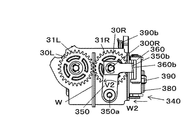
- the wire feed portion 3A is an example of a wire feed means constituting the feed means, and as a pair of feed members that send the parallel wires W, a spur gear-like first feed gear 30L that sends the wires W by a rotating operation, Similarly, a spur gear-like second feed gear 30R is provided which sandwiches the wire W with the first feed gear 30L.
- the first feed gear 30L and the second feed gear 30R have a spur gear shape in which teeth are formed on the outer peripheral surface of a disk-shaped member.
- the first feed gear 30L and the second feed gear 30R can mesh with each other and transmit the driving force from one feed gear to the other feed gear to appropriately feed the two wires W. As long as it is a thing, it is not necessarily limited to a spur gear.
- the first feed gear 30L and the second feed gear 30R are examples of a rotary feed member, and each is constituted by a disk-shaped member.
- the wire feed portion 3A is configured such that the first feed gear 30L and the second feed gear 30R are provided across the feed path of the wire W, so that the outer peripheral surfaces of the first feed gear 30L and the second feed gear 30R They face each other.
- the first feed gear 30L and the second feed gear 30R sandwich the two wires W arranged in parallel between the opposed portions of the outer peripheral surface.
- the first feed gear 30L and the second feed gear 30R send along the extending direction of the wire W in a state where the two wires W are arranged in parallel.
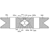
- FIG. 3 is a configuration diagram showing an example of the feed gear of the present embodiment.
- FIG. 3 is a cross-sectional view taken along the line BB of FIG.
- the first feed gear 30L includes a tooth portion 31L on the outer peripheral surface.
- the second feed gear 30R includes a tooth portion 31R on the outer peripheral surface.
- the first feed gear 30L and the second feed gear 30R are arranged in parallel so that the tooth portions 31L and 31R face each other.
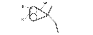
- the first feed gear 30L and the second feed gear 30R are formed by the axial direction Ru1 of the loop Ru formed by the wire W wound around the curl guide portion 5A, that is, by the wire W.
- the loops Ru are juxtaposed in a direction along the axial direction of a virtual circle that is regarded as a circle.
- the axial direction Ru1 of the loop Ru formed by the wire W wound by the curl guide portion 5A is also referred to as the axial direction Ru1 of the loop-shaped wire W.
- the first feed gear 30L includes a first feed groove 32L on the outer peripheral surface.
- the second feed gear 30R includes a second feed groove portion 32R on the outer peripheral surface.
- the first feed gear 30L and the second feed gear 30R are arranged so that the first feed groove portion 32L and the second feed groove portion 32R face each other.
- the first feed groove 32L is formed in a V-groove shape on the outer peripheral surface of the first feed gear 30L along the rotation direction of the first feed gear 30L.
- the first feed groove portion 32L has a first inclined surface 32La and a second inclined surface 32Lb that form a V-groove.
- the first feed groove 32L is formed in a V-groove shape so that the first inclined surface 32La and the second inclined surface 32Lb face each other at a predetermined angle.
- the first feed groove portion 32L is, of the outermost wires of the parallel wires W.
- a part of the outer peripheral surface of one wire W1 of the two wires W arranged in parallel is configured to be in contact with the first inclined surface 32La and the second inclined surface 32Lb.
- the second feed groove portion 32R is formed in a V-groove shape on the outer peripheral surface of the second feed gear 30R along the rotation direction of the second feed gear 30R.
- the second feed groove 32R has a first inclined surface 32Ra and a second inclined surface 32Rb that form a V-groove.
- the second feed groove 32R has a V-shaped cross section, and the first inclined surface 32Ra and the second inclined surface 32Rb face each other at a predetermined angle.
- the second feed groove portion 32R is out of the outermost wires of the parallel wires W
- a part of the outer peripheral surface of the other wire W2 of the two wires W arranged in parallel is configured to be in contact with the first inclined surface 32Ra and the second inclined surface 32Rb.
- the first feed groove 32L has one of the wires W1 in contact with the first inclined surface 32La and the second inclined surface 32Lb.
- the depth at which the portion on the side facing the second feed gear 30R protrudes from the root circle 31La of the first feed gear 30L (of the first inclined surface 32La and the second inclined surface 32Lb) Consists of angles.
- the second feed groove portion 32R is formed of the other wire W2 in contact with the first inclined surface 32Ra and the second inclined surface 32Rb.
- one wire W1 is connected to the first inclined surface 32La of the first feed groove 32L. Pressed by the second inclined surface 32Lb, the other wire W2 is pressed by the first inclined surface 32Ra and the second inclined surface 32Rb of the second feed groove 32R. Then, one wire W1 and the other wire W2 are pressed against each other. Accordingly, when the first feed gear 30L and the second feed gear 30R are rotated, the two wires W (one wire W1 and the other wire W2) are turned into the first feed gear 30L and the second feed gear 30L. The gears 30R are simultaneously sent in contact with each other.
- the first feed groove portion 32L and the second feed groove portion 32R have V-shaped cross sections, but are not necessarily limited to the V-groove shape.
- the first feed groove portion 32L and the second feed groove portion 32R may be trapezoidal or arcuate. May be.
- the first feed gear 30L and the second feed gear 30R are interposed between the first feed gear 30L and the second feed gear 30R. It is good also as a structure provided with the transmission mechanism comprised from the even number of gears etc. which rotate the gear 30R to a mutually reverse direction.
- the wire feed unit 3A includes a drive unit 33 that drives the first feed gear 30L, and a displacement unit 34 that presses and separates the second feed gear 30R from the first feed gear 30L.
- the drive unit 33 includes a transmission mechanism 33b configured by a combination of a feed motor 33a that drives the first feed gear 30L and a gear that transmits the driving force of the feed motor 33a to the first feed gear 30L.
- the first feed gear 30L rotates when the rotation operation of the feed motor 33a is transmitted via the transmission mechanism 33b.
- the rotation of the first feed gear 30L is transmitted to the tooth portion 31R via the tooth portion 31L, and the second feed gear 30R rotates following the first feed gear 30L.
- the first feed gear 30L and the second feed gear 30R rotate, so that the friction force generated between the first feed gear 30L and one wire W1, the second feed gear 30R and the other feed gear 30R.
- the two wires W are fed in parallel by the frictional force generated between the wires W2 and the frictional force generated between one wire W1 and the other wire W2.
- the wire feed unit 3A switches the rotation direction of the first feed gear 30L and the second feed gear 30R by switching the rotation direction of the feed motor 33a and switches the rotation direction of the wire W. It is done.
- the wire W is moved in the forward direction indicated by the arrow X1, that is, in the direction of the curl guide portion 5A by causing the wire feed portion 3A to rotate the first feed gear 30L and the second feed gear 30R forward.
- the curled guide 5A is wound around the reinforcing bar S.
- the first feed gear 30L and the second feed gear 30R are reversed so that the wire W is fed in the reverse direction indicated by the arrow X2, that is, in the direction of the magazine 2A.
- the wire W is brought into close contact with the reinforcing bar S by being pulled back after the wire W is wound around the reinforcing bar S.
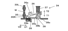
- FIG. 4A, FIG. 4B, FIG. 4C, and FIG. 4D are configuration diagrams showing an example of a displacement portion of the present embodiment.
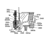
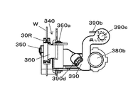
- the displacement portion 34 is an example of a displacement means, and is a first operation that displaces the second feed gear 30R in the direction of separating and contacting the first feed gear 30L by a rotation operation with the shaft 34a shown in FIG. 2 as a fulcrum.
- a displacement member 35 and a second displacement member 36 for displacing the first displacement member 35 are provided.
- the second feed gear 30R is pressed in the direction of the first feed gear 30L by a spring 37 that urges the second displacement member 36 that is displaced by a rotation operation with the shaft 36a as a fulcrum.
- the two wires W are sandwiched between the first feed groove 32L of the first feed gear 30L and the second feed groove 32R of the second feed gear 30R. Further, the tooth portion 31L of the first feed gear 30L and the tooth portion 31R of the second feed gear 30R are engaged with each other.
- the relationship between the first displacement member 35 and the second displacement member 36 is that the second displacement member 36 is displaced to bring the first displacement member 35 into a free state, whereby the second feed gear 30R.
- a mechanism in which the first displacement member 35 and the second displacement member 36 are interlocked may be used.
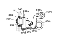
- the displacement unit 34 includes an operation button 38 that presses the second displacement member 36 and a release lever 39 that locks and unlocks the operation button 38.
- the operation button 38 is an example of an operation member, protrudes outward from the main body 10A, and is supported so as to be movable in directions indicated by arrows T1 and T2.
- the operation button 38 is a first locking mechanism in which the release lever 39 is locked at a wire feed position where the wire W can be fed by the first feed gear 30L and the second feed gear 30R.
- a second latch in which the release lever 39 is locked at a wire loading position where the wire W can be loaded by separating the locking recess 38a, the first feed gear 30L, and the second feed gear 30R.
- a recess 38b is provided.
- the release lever 39 is an example of a release member, and is supported so as to be movable in the directions indicated by the arrows U1 and U2 intersecting the moving direction of the operation button 38.
- the release lever 39 includes a locking projection 39a that is locked to the first locking recess 38a and the second locking recess 38b of the operation button 38 as a locking mechanism.
- the release lever 39 is urged by a spring 39b in the direction of the arrow U1 approaching the operation button 38, and the locking projection 39a enters the first locking recess 38a of the operation button 38 in the wire feed position shown in FIG. 5A.
- the engaging projection 39a is engaged with the second engaging recess 38b of the operation button 38 in the wire loading position shown in FIG. 5B.
- a guiding slope 39c is formed on the locking projection 39a along the moving direction of the operation button 38.
- the release lever 39 is moved in the direction indicated by the arrow U2 by the guide slope 39c being pushed by the operation of the operation button 38 in the wire feed position being pushed in the direction indicated by the arrow T2, and the locking projection 39a coming off from the first locking recess 38a. It is displaced to.
- the displacement part 34 is a direction substantially orthogonal to the feed direction of the wire W fed by the first feed gear 30L and the second feed gear 30R in the wire feed part 3A, and is the first feed gear 30L and the second feed gear 30L.
- the second displacement member 36 is provided behind the feed gear 30R, that is, on the handle portion 11A side with respect to the wire feed portion 3A in the main body portion 10A.
- the operation button 38 and the release lever 39 are also provided behind the first feed gear 30L and the second feed gear 30R, that is, on the handle portion 11A side with respect to the wire feed portion 3A in the main body portion 10A.
- the displacement portion 34 is configured such that the locking protrusion 39a of the release lever 39 is locked to the second locking recess 38b of the operation button 38 and the operation button 38 is operated. Button 38 is held in the wire loading position.
- FIG. 5A, FIG. 5B, and FIG. 5C are configuration diagrams showing an example of the parallel guide according to the present embodiment.
- FIGS. 5A, 5B, and 5C are cross-sectional views taken along the line CC of FIG. 2, and show the cross-sectional shape of the parallel guide 4A provided at the introduction position P1.
- 2 is a sectional view taken along the line DD of FIG. 2 showing the sectional shape of the parallel guide 4A provided at the intermediate position P2, and the EE line of FIG. 2 showing the sectional shape of the parallel guide 4A provided at the cutting and discharging position P3.
- the cross-sectional view shows a similar shape.
- FIG. 5D is a configuration diagram illustrating an example of parallel wires
- FIG. 5E is a configuration diagram illustrating an example of wires twisted in an intersecting manner.
- the parallel guide 4A is an example of a restricting means that constitutes a sending means, and restricts the direction of a plurality of (two or more) wires W that have been sent.
- the parallel guide 4A sends out two or more wires W that have entered in parallel.
- the parallel guide 4A parallels two or more wires along a direction orthogonal to the feeding direction of the wires W. Specifically, two or more wires W are juxtaposed along the axial direction of the loop-shaped wire W wound around the reinforcing bar S by the curl guide portion 5A.
- 4 A of parallel guides have the wire control part (for example, opening 4AW mentioned later) which controls the direction of the said 2 or more wire W, and makes it parallel.
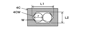
- the parallel guide 4A includes a guide body 4AG, and the guide body 4AG is formed with an opening 4AW which is a wire restricting portion for allowing a plurality of wires W to pass (insert).
- the opening 4AW penetrates the guide body 4AG along the feeding direction of the wire W.
- the opening 4AW is arranged so that the plurality of wires W are arranged in parallel when the plurality of wires W that have been sent pass through the opening 4AW and after the passage (the plurality of wires W are in the feed direction of the wires W ( The shape is determined such that the wires W are arranged in a direction (radial direction) orthogonal to the axial direction and the axes of the plurality of wires W are substantially parallel to each other.
- the plurality of wires W that have passed through the parallel guide 4A exit from the parallel guide 4A in a parallel state.
- the parallel guide 4A regulates the direction in which the two wires W are arranged in the radial direction so that the two wires W are in parallel.
- the opening 4AW has a shape in which one direction orthogonal to the feeding direction of the wire W is orthogonal to the feeding direction of the wire W and longer than the other direction orthogonal to the one direction.
- the opening 4AW is a direction in which the longitudinal direction (two or more wires W can be arranged in parallel) is orthogonal to the feeding direction of the wire W, more specifically, the axis of the wire W looped by the curl guide portion 5A.
- the two or more wires W inserted through the opening 4AW are fed in parallel so as to be aligned in the direction orthogonal to the feeding direction of the wire W, that is, in the axial direction of the wire W formed in the loop shape.
- the opening 4AW (the cross section thereof) is a circle having a diameter that is twice or more the diameter of the wire W, or the length of one side is a substantially square that is twice or more the diameter of the wire W.
- the two wires W passing through the opening 4AW can be freely moved in the radial direction.
- the two wires W that pass through the opening 4AW can move freely in the radial direction in the opening 4AW, the direction in which the two wires W are arranged in the radial direction cannot be regulated, and the two wires 2 that have come out of the opening 4AW.
- the wires W of the book may be twisted or crossed without being parallel.
- the opening 4AW has a length in the one direction, that is, a length L1 in the longitudinal direction, and a plurality (n) of diameters r of the wires W in a form in which a plurality of (n) wires W are arranged along the radial direction.
- the length is slightly longer than the length of the wire W, and the length in the other direction, that is, the length L2 in the short direction, is slightly longer than the diameter r of one wire W.
- the opening 4AW has a length L1 in the longitudinal direction slightly longer than the diameter r of two wires W, and a length L2 in the short direction is a diameter of one wire W. It has a length slightly longer than r.
- the parallel guide 4A is configured such that the longitudinal direction of the opening 4AW is linear, and the lateral direction is arcuate, but is not limited thereto.
- the preferable length L2 in the short direction of the parallel guide 4A is slightly longer than the diameter r of one wire W.
- the longitudinal direction of the parallel guide 4A is wound around the reinforcing bar S by the curl guide portion 5A.
- the length L2 of the parallel guide 4A in the short direction is a diameter r of one wire W as shown in FIG. 5B.
- the length may be in a range from a slightly longer length to a length shorter than the diameter r of two wires W.
- the parallel guide 4A is short.
- the length L2 in the direction may be in a range from a length slightly longer than the diameter r of one wire W to a length shorter than the diameter r of two wires W.
- the longitudinal direction of the opening 4AW is the direction along the direction orthogonal to the feeding direction of the wire W.
- the loop-shaped wire W wound around the reinforcing bar S by the curl guide portion 5A Arranged in the direction along the axial direction Ru1.
- the parallel guide 4A can pass two wires in parallel along the axial direction Ru1 of the loop-shaped wire W.
- the parallel guide 4A has a length L2 in the short direction of the opening 4AW that is shorter than twice the diameter r of the wire W and slightly longer than the diameter r of the wire W. Even when the length L1 in the direction is sufficiently longer than a plurality of diameters r of the wires W, the wires W can be passed in parallel.
- the longer the length L2 in the short direction (for example, a length close to twice the length r of the diameter r of the wire W) and the longer the length L1 in the longitudinal direction, the more free the wire W is in the opening 4AW. You will be able to move on. If it does so, the axis
- the length L1 in the longitudinal direction of the opening 4AW is preferably slightly longer than twice the diameter r of the wire W so that the two wires W are arranged in parallel along the radial direction.
- the length L2 in the short direction is also preferably slightly longer than the diameter r of the wire W.
- the parallel guide 4A is provided at predetermined positions on the upstream side and the downstream side of the first feed gear 30L and the second feed gear 30R (wire feed unit 3A) with respect to the feed direction in which the wire W is fed in the forward direction. .
- the parallel guide 4A By providing the parallel guide 4A on the upstream side of the first feed gear 30L and the second feed gear 30R, the two wires W in parallel enter the wire feed portion 3A. For this reason, the wire feeder 3A can feed the wires W appropriately (in parallel).
- the parallel guide 4A also on the downstream side of the first feed gear 30L and the second feed gear 30R, while maintaining the parallel state of the two wires W sent from the wire feed portion 3A, The wire W can be sent further downstream.
- the parallel guide 4A provided on the upstream side of the first feed gear 30L and the second feed gear 30R is arranged so that the wires W fed to the wire feed section 3A are arranged in parallel in the predetermined direction described above. Therefore, it is provided at the introduction position P1 between the first feed gear 30L and the second feed gear 30R and the magazine 2A.
- one of the parallel guides 4A provided on the downstream side of the first feed gear 30L and the second feed gear 30R is a state in which the wires W sent to the cutting portion 6A are arranged in parallel in the predetermined direction described above. Therefore, it is provided at an intermediate position P2 between the first feed gear 30L and the second feed gear 30R and the cutting portion 6A.
- another one of the parallel guides 4A provided on the downstream side of the first feed gear 30L and the second feed gear 30R is that the wires W fed to the curl guide portion 5A are parallel in the predetermined direction described above. In order to be in the state of being cut, it is provided at the cutting discharge position P3 where the cutting part 6A is arranged.
- the parallel guide 4A provided at the introduction position P1 has the above-described shape in which at least the downstream side of the opening 4AW restricts the radial direction of the wire W with respect to the feeding direction of the wire W fed in the forward direction.
- the opening area on the side (wire introduction part) facing the magazine 2A upstream of the opening 4AW with respect to the feeding direction of the wire W fed in the forward direction is larger than that on the upstream side.
- the opening area of the opening 4AW gradually increases from the cylindrical hole portion that regulates the direction of the wire W and the upstream end portion of the cylindrical hole portion to the inlet portion of the opening 4AW that is the wire introduction portion.
- a hole having a conical shape (funnel shape, taper shape). In this way, the opening area of the wire introduction portion is maximized, and the opening area is gradually reduced from there, thereby making it easier for the wire W to enter the parallel guide 4. Therefore, the work of introducing the wire W into the opening 4AW can be easily performed.
- the other parallel guide 4A has the same configuration, and the opening 4AW on the downstream side with respect to the feeding direction of the wire W fed in the forward direction has the above-described shape that regulates the radial direction of the wire W.
- the other parallel guides 4 may also be configured such that the opening area of the upstream opening with respect to the feeding direction of the wire W fed in the forward direction is larger than the opening area of the downstream opening.
- the parallel guide 4A provided at the introduction position P1, the parallel guide 4A provided at the intermediate position P2, and the parallel guide 4A provided at the cutting discharge position P3 have the longitudinal direction of the opening 4AW orthogonal to the feed direction of the wire W.
- the loop-shaped wire W wound around the reinforcing bar S is arranged in the direction along the axial direction Ru1.
- the two wires W fed by the first feed gear 30L and the second feed gear 30R are moved in the axial direction Ru1 of the loop-shaped wire W wound around the reinforcing bar S as shown in FIG. 5D.
- the two wires W are restrained from crossing and twisting during feeding.
- the opening 4AW is a cylindrical hole portion having a predetermined depth (a predetermined distance or depth from the inlet of the opening 4AW to the outlet) from the inlet of the opening 4AW to the outlet (in the feed direction of the wire W).
- the shape of the opening 4AW is not limited to this.
- the opening 4AW may be a flat hole having almost no depth opened in the plate-shaped guide body 4AG.
- the opening 4AW may be a groove-shaped guide (for example, a U-shaped guide groove having an upper opening) instead of a hole that penetrates the guide body 4AG.
- the opening area of the entrance part of opening 4AW which is a wire introduction part was made larger than another part, it does not necessarily need to be larger than another part.
- the shape of the opening 4AW is not limited to a specific shape as long as the plurality of wires that have passed through the opening 4AW and have come out of the parallel guide 4A are in a parallel state.
- the parallel guide 4A is provided at the upstream side (introduction position P1) and the downstream side of the first feed gear 30L and the second feed gear 30R (intermediate position P2 and cutting discharge position P3).
- the position where the parallel guide 4A is installed is not necessarily limited to these three places. That is, the parallel guide 4A may be installed only at the introduction position P1, only at the intermediate position P2, or only at the cutting / discharging position P3, and only at the introducing position P1 and the intermediate position P2, only at the introducing position P1 and the cutting / discharging position P3, or in the middle. You may install only in position P2 and cutting discharge position P3.
- parallel guides 4A may be installed at any position between the introduction position P1 and the curl guide portion 5A on the downstream side of the cutting and discharging position P3.
- the introduction position P1 includes the inside of the magazine 2A. That is, the parallel guide 4A may be arranged in the vicinity of the outlet from which the wire W is drawn out inside the magazine 2A.
- the curl guide portion 5A is an example of a guide unit that constitutes a feeding unit, and forms a conveyance path in which two wires W are looped and wound around the reinforcing bar S.
- the curl guide portion 5A includes a first guide portion 50 for winding the wire W fed by the first feed gear 30L and the second feed gear 30R, and the wire W fed from the first guide portion 50.
- a second guide part 51 for guiding to the binding part 7A is provided.
- the first guide portion 50 includes guide grooves 52 that form a feed path of the wire W, and guide pins 53 and 53b as guide members that wind the wire W in cooperation with the guide groove 52.
- FIG. 6 is a configuration diagram showing an example of the guide groove of the present embodiment. Here, FIG. 6 is a cross-sectional view taken along the line GG of FIG.
- the guide groove 52 constitutes a guide portion and regulates the radial direction of the wire W perpendicular to the feed direction of the wire W together with the parallel guide 4A, in this example, one direction perpendicular to the feed direction of the wire W is Similarly, it is configured by an opening having a shape that is orthogonal to the feeding direction of the wire W and longer than the other direction orthogonal to one direction.
- the guide groove 52 has a length L1 in the longitudinal direction, that is, a length slightly longer than a plurality of diameters r of the wires W in the form in which the wires W are arranged in the radial direction,
- the length L2 in the short direction is slightly longer than the diameter r of one wire W.
- the guide groove 52 has a length L1 in the longitudinal direction slightly longer than the diameter r of two wires W.
- the guide groove 52 is arranged such that the longitudinal direction of the opening is along the axial direction Ru1 of the loop-shaped wire W. Note that the guide groove 52 need not necessarily have a function of regulating the radial direction of the wire W. In that case, the length (length) of the guide groove 52 in the longitudinal direction and the lateral direction is not limited to the above-described dimensions.
- the guide pin 53 is provided on the introduction portion side of the wire W fed by the first feed gear 30L and the second feed gear 30R in the first guide portion 50, and with respect to the feed path of the wire W by the guide groove 52. , The inner side of the loop Ru formed by the wire W in the radial direction.
- the guide pin 53 regulates the feed path of the wire W so that the wire W fed along the guide groove 52 does not enter the inner side in the radial direction of the loop Ru formed by the wire W.
- the guide pin 53b is provided on the discharge portion side of the wire W fed by the first feed gear 30L and the second feed gear 30R in the first guide portion 50, and with respect to the feed path of the wire W by the guide groove 52.
- the loop Ru formed by the wire W is disposed outside in the radial direction.
- the wire W fed by the first feed gear 30L and the second feed gear 30R has at least two points on the radially outer side of the loop Ru formed by the wire W and at least one point inside the two points. By restricting the radial position of the loop Ru formed by the wire W at three points, the wire W is curled.
- the radially outer position of the loop Ru formed by the wire W is regulated.
- the position of the inner side in the radial direction of the loop Ru formed by the wire W is regulated by the guide pin 53.
- the curl guide portion 5A includes a retracting mechanism 53a that retracts the guide pin 53 from the path along which the wire W moves by the operation of winding the wire W around the reinforcing bar S.
- the retraction mechanism 53a is displaced in conjunction with the operation of the binding portion 7A after the wire W is wound around the reinforcing bar S, and the wire W moves on the guide pin 53 before the timing when the wire W is wound around the reinforcing bar S. Evacuate from the route.
- the second guide portion 51 is a third guide portion that regulates the radial position of the loop Ru formed by the wire W wound around the reinforcing bar S (the movement of the wire W in the radial direction of the loop Ru).
- a movable guide part 55 is provided as a guide part.
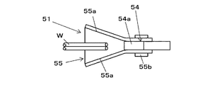
- FIG. 8A, FIG. 8B, FIG. 9A and FIG. 9B are configuration diagrams showing an example of the second guide portion.
- FIG. 7 is a plan view of the second guide portion 51 as viewed from above.
- 8B is a side view of the second guide portion 51 as viewed from one side, and
- FIGS. 9A and 9B are side views of the second guide portion 51 as viewed from the other side.
- the fixed guide portion 54 is provided with a wall surface 54a with a surface extending along the feed direction of the wire W outside the radial direction of the loop Ru formed by the wire W wound around the reinforcing bar S.
- the fixed guide portion 54 regulates the radial position of the loop Ru formed by the wire W wound around the reinforcing bar S at the wall surface 54a.
- the fixed guide portion 54 is fixed to the main body portion 10 ⁇ / b> A of the reinforcing bar binding machine 1 ⁇ / b> A, and its position is fixed with respect to the first guide portion 50.
- the fixed guide portion 54 may be integrally formed with the main body portion 10A.
- the fixed guide portion 54 which is a separate part, is attached to the main body portion 10A
- the fixed guide portion 54 is not completely fixed to the main body portion 10A, but the wire W is operated by forming the loop Ru. It may be movable to such an extent that movement can be regulated.
- the movable guide portion 55 is provided on the distal end side of the second guide portion 51, and on both sides along the axial direction Ru1 of the loop Ru formed by the wire W wound around the reinforcing bar S, the movable guide portion 55 is arranged in the radial direction of the loop Ru.
- a wall surface 55a by a surface rising from the wall surface 54a toward the inside is provided.
- the movable guide portion 55 has a shape in which the interval between the wall surfaces 55a is widened at the distal end side where the wire W fed from the first guide portion 50 enters and narrows toward the fixed guide portion 54b, and the wall surface 55a is tapered. Yes. As a result, the position of the wire Ru sent out from the first guide portion 50 in the axial direction Ru1 of the loop Ru wound around the reinforcing bar S is regulated by the wall surface 55a of the movable guide portion 55 and fixed by the movable guide portion 55. It is guided to the guide part 54.
- the other end side of the movable guide portion 55 opposite to the one end side, which is the tip end side into which the wire W fed from the first guide portion 50 enters, is supported by the fixed guide portion 54 by the shaft 55b.
- the movable guide portion 55 is a rotation operation about the shaft 55b along the axial direction Ru1 of the loop Ru formed by the wire W wound around the reinforcing bar S, and the wire W fed from the first guide portion 50 is a fulcrum.
- the front end side into which is inserted opens and closes in a direction away from and in contact with the first guide portion 50.
- the reinforcing bar binding machine When binding the reinforcing bar S, the reinforcing bar binding machine is a pair of guide members provided for winding the wire W around the reinforcing bar S, in this example, between the first guide part 50 and the second guide part 51. Bundling work is performed after S is set. When the binding work is completed, the first guide part 50 and the second guide part 51 are pulled out from the reinforcing bar S after the binding is completed in order to perform the next binding work. When the first guide part 50 and the second guide part 51 are pulled out from the reinforcing bar S, the reinforcing bar binding machine 1A is moved in the direction of arrow Z3 (see FIG. 1), which is one direction away from the reinforcing bar S.
- the reinforcing bar binding machine 1A is moved in the direction of the arrow Z3 for each binding. If it is troublesome and can be moved in the direction of the arrow Z2, the work can be performed quickly.
- the guide member corresponding to the second guide portion 51 referred to in this example is fixed to the binding machine main body. If the guide member is moved in the arrow Z2 direction, the guide member is caught by the reinforcing bar S.
- the second guide part 51 (movable guide part 55) is made movable as described above, and the reinforcing bar binding machine 1A is moved in the direction of the arrow Z2, so that the first guide part 50 and the second guide part 50
- the rebar S is configured to pass through between the guide portions 51.
- the movable guide portion 55 can guide the wire W sent out from the first guide portion 50 to the second guide portion 51 by a rotation (turning) operation with the shaft 55b as a fulcrum,
- the rebar binding machine 1A is moved in the direction of the arrow Z2, and is opened and closed between the retraction position where the rebar binding machine 1A is withdrawn from the rebar S.
- the movable guide portion 55 is urged in a direction in which the distance between the distal end side of the first guide portion 50 and the distal end side of the second guide portion 51 approaches by an urging means (urging portion) such as a torsion coil spring 57.
- the guide coil shown in FIGS. 8A and 9A is held by the force of the torsion coil spring 57.
- the movable guide part 55 opens from the guide position to the retracted position shown in FIGS. 8B and 9B.
- the guide position is a position where the wall surface 55a of the movable guide portion 55 exists at a position where the wire W forming the loop Ru passes.
- the retreat position is a position where the reinforcing bar S can push the movable guide part 55 by the movement of the reinforcing bar binding machine 1 ⁇ / b> A and the reinforcing bar S can come out between the first guide part 50 and the second guide part 51.
- the direction in which the reinforcing bar binding machine 1A is moved is not unique, and the reinforcing bar S can be pulled out between the first guide part 50 and the second guide part 51 even if the movable guide part 55 moves slightly from the guide position.
- the retracted position includes a position slightly moved from the guide position.
- the reinforcing bar binding machine 1 ⁇ / b> A includes a guide opening / closing sensor 56 that detects opening / closing of the movable guide portion 55.
- the guide opening / closing sensor 56 detects a closed state and an open state of the movable guide portion 55, and outputs a predetermined detection signal.
- the cutting portion 6A includes a fixed blade portion 60, a rotary blade portion 61 that cuts the wire W in cooperation with the fixed blade portion 60, and the operation of the binding portion 7A.
- a moving mechanism 62 that transmits the moving operation to the rotary blade portion 61 and rotates the rotary blade portion 61 is provided.
- the fixed blade portion 60 is configured by providing an edge portion capable of cutting the wire W at an opening through which the wire W passes.
- the fixed blade part 60 is configured by a parallel guide 4A disposed at the cutting / discharging position P3.
- the rotary blade portion 61 cuts the wire W passing through the parallel guide 4A of the fixed blade portion 60 by a rotation operation with the shaft 61a as a fulcrum.
- the transmission mechanism 62 is displaced in conjunction with the operation of the binding portion 7A, and after the wire W is wound around the reinforcing bar S, the rotating blade portion 61 is rotated in accordance with the timing of twisting the wire W to cut the wire W. .
- the binding portion 7A is an example of a binding unit, and a gripping portion 70 that grips the wire W, and one end WS side and the other end WE side of the wire W gripped by the gripping portion 70 are bent toward the reinforcing bar S side.
- a bending portion (bending portion) 71 is provided.
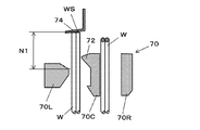
- the grip portion 70 is an example of a grip means, and includes a fixed grip member 70C, a first movable grip member 70L, and a second movable grip member 70R as shown in FIG.
- the first movable gripping member 70L and the second movable gripping member 70R are arranged in the left-right direction via the fixed gripping member 70C.
- the first movable gripping member 70L is disposed on one side along the axial direction of the wire W to be wound with respect to the fixed gripping member 70C
- the second movable gripping member 70R is on the other side. It is arranged on the side.
- the first movable gripping member 70L is displaced in a direction in which it is separated from the fixed gripping member 70C.
- the second movable gripping member 70R is displaced in a direction to be separated from and contacting the fixed gripping member 70C.
- the gripper 70 moves in a direction in which the first movable gripping member 70L moves away from the fixed gripping member 70C, thereby forming a feed path through which the wire W passes between the first movable gripping member 70L and the fixed gripping member 70C. Is done. In contrast, when the first movable gripping member 70L moves in a direction approaching the fixed gripping member 70C, the wire W is gripped between the first movable gripping member 70L and the fixed gripping member 70C.
- the gripper 70 moves in a direction in which the second movable gripping member 70R moves away from the fixed gripping member 70C, so that the wire W passes between the second movable gripping member 70R and the fixed gripping member 70C. Is formed.
- the wire W is gripped between the second movable gripping member 70R and the fixed gripping member 70C by moving the second movable gripping member 70R in a direction approaching the fixed gripping member 70C.
- the wire W that has been fed by the first feed gear 30L and the second feed gear 30R and passed through the parallel guide 4A at the cutting and discharging position P3 passes between the fixed gripping member 70C and the second movable gripping member 70R, and curls. Guided to the guide portion 5A.
- the wire W that is curled by the curl guide portion 5A passes between the fixed gripping member 70C and the first movable gripping member 70L.
- a first gripping portion that grips one end WS side of the wire W is configured by a pair of gripping members of the fixed gripping member 70C and the first movable gripping member 70L.
- the fixed gripping member 70C and the second movable gripping member 70R constitute a second gripping part that grips the other end WE side of the wire W cut by the cutting part 6A.
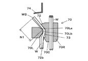
- FIG. 10A and FIG. 10B are main part configuration diagrams of the gripping part of the present embodiment.
- the first movable gripping member 70L has a convex portion 70Lb projecting in the direction of the fixed gripping member 70C on the surface facing the fixed gripping member 70C.
- the fixed gripping member 70C has a concave portion 73 in which the convex portion 70Lb of the first movable gripping member 70L enters on the surface facing the first movable gripping member 70L. Therefore, when the wire W is gripped by the first movable gripping member 70L and the fixed gripping member 70C, the wire W bends toward the first movable gripping member 70L.
- the fixed gripping member 70 ⁇ / b> C includes a preliminary bending portion 72.
- the pre-bending portion 72 is a surface facing the first movable gripping member 70L of the fixed gripping member 70C, and the first movable gripping member is disposed at the downstream end along the feeding direction of the wire W fed in the forward direction. Convex portions projecting in the 70L direction are provided.
- the gripping part 70 grips the wire W between the fixed gripping member 70C and the first movable gripping member 70L, and prevents the gripped wire W from being pulled out by providing the fixed gripping member 70C with a convex part 72b and a concave part 73.
- the convex portion 72b is a surface facing the first movable gripping member 70L of the fixed gripping member 70C, and is provided at the upstream end along the feeding direction of the wire W fed in the forward direction. Projecting in the direction of the member 70L.
- the concave portion 73 is provided between the preliminary bent portion 72 and the convex portion 72b, and has a concave shape in the direction opposite to the first movable gripping member 70L.
- the first movable gripping member 70L has a concave portion 70La in which the pre-bending portion 72 of the fixed gripping member 70C enters, and a convex portion 70Lb in which the concave portion 73 of the fixed gripping member 70C enters.
- the wire W is moved by the pre-bending portion 72 by the operation of gripping the one end WS side of the wire W between the fixed gripping member 70C and the first movable gripping member 70L.
- One end of the wire W is pressed toward the first movable gripping member 70L, and the one end WS of the wire W is bent away from the wire W gripped by the fixed gripping member 70C and the second movable gripping member 70R.
- Holding the wire W by the fixed gripping member 70C and the second movable gripping member 70R includes a state in which the wire W can move to some extent between the fixed gripping member 70C and the second movable gripping member 70R. This is because in the operation of winding the wire W around the reinforcing bar S, the wire W needs to move between the fixed gripping member 70C and the second movable gripping member 70R.
- the bending portion 71 is an example of a bending means, and the wire W is placed so that the end of the wire W after binding the bundle is positioned closer to the bundle than the top of the wire W that protrudes most in the direction away from the bundle. Bend.
- the bending portion 71 bends the wire W gripped by the grip portion 70 before twisting the wire W by the grip portion 70.
- the bending portion 71 is provided around the gripping portion 70 so as to cover a part of the gripping portion 70, and is provided so as to be movable along the axial direction of the gripping portion 70.
- the bending portion 71 includes one end WS side of the wire W gripped by the fixed gripping member 70C and the first movable gripping member 70L, and the fixed gripping member 70C and the second movable gripping member 70R.
- the bending portion 71 grips one end WS side of the wire W gripped by the fixed gripping member 70C and the first movable gripping member 70L by moving in the forward direction indicated by the arrow F (see FIG. 1). Bend to the reinforcing bar S side with the position as a fulcrum. Further, the bending portion 71 moves in the forward direction indicated by the arrow F, so that the other end WE side of the wire W between the fixed gripping member 70C and the second movable gripping member 70R is supported at the gripping position. Bend toward the reinforcing bar S side.
- the wire W passing between the second movable gripping member 70R and the fixed gripping member 70C is pressed by the bending portion 71, and the fixed gripping member 70C and the second movable gripping are held.
- the wire W is prevented from coming off from between the member 70R.
- the binding unit 7A includes a length regulating unit 74 that regulates the position of one end WS of the wire W.
- the length restricting portion 74 is configured by providing a member with which one end portion WS of the wire W is abutted on the feeding path of the wire W that has passed between the fixed gripping member 70C and the first movable gripping member 70L.
- the length restricting portion 74 is provided in the first guide portion 50 of the curl guide portion 5A in order to secure a predetermined distance from the holding position of the wire W by the fixed holding member 70C and the first movable holding member 70L. It is done.
- the reinforcing bar binding machine 1A includes a binding unit driving mechanism 8A that drives the binding unit 7A.
- the binding unit driving mechanism 8A includes a motor 80, a rotary shaft 82 driven by the motor 80 via a speed reducer 81 that performs deceleration and torque amplification, a movable member 83 that is displaced by the rotation of the rotary shaft 82, and a rotation.
- a rotation restricting member 84 that restricts the rotation of the movable member 83 in conjunction with the rotating operation of the shaft 82 is provided.
- the rotating shaft 82 and the movable member 83 are rotated in the front-rear direction along the rotating shaft 82 of the movable member 83 by the screw portion provided on the rotating shaft 82 and the nut portion provided on the movable member 83. Converted to move.
- the movable member 83 is in a state where the rotation operation is restricted by the rotation restricting member 84 by being locked to the rotation restricting member 84 in the operation range in which the wire W is grasped by the grasping portion 70 and the wire W is bent by the bending portion 71. To move back and forth. In addition, the movable member 83 is rotated by the rotation operation of the rotation shaft 82 by being removed from the engagement of the rotation restricting member 84.
- the movable member 83 is connected to the first movable gripping member 70L and the second movable gripping member 70R via a cam (not shown).
- the binding unit driving mechanism 8A is configured such that the movement of the movable member 83 in the front-rear direction displaces the first movable gripping member 70L in the direction of separating and contacting the fixed gripping member 70C, and the second movable gripping member 70R is fixed. It is converted into an operation of displacing in the direction in which the gripping member 70C is moved away from and contacting the gripping member 70C.
- the rotation operation of the movable member 83 is converted into the rotation operations of the fixed gripping member 70C, the first movable gripping member 70L, and the second movable gripping member 70R.
- the bending portion 71 is provided integrally with the movable member 83, and the bending portion 71 moves in the front-rear direction by the movement of the movable member 83 in the front-rear direction.
- the retraction mechanism 53 a of the guide pin 53 described above is configured by a link mechanism that converts the movement of the movable member 83 in the front-rear direction into the displacement of the guide pin 53.
- the transmission mechanism 62 of the rotary blade portion 61 is configured by a link mechanism that converts the movement of the movable member 83 in the front-rear direction into the rotation operation of the rotary blade portion 61.
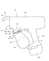
- FIG. 11 is an external view showing an example of a reinforcing bar binding machine according to the present embodiment.
- Reinforcing bar binding machine 1A of the present embodiment is a form that an operator uses in his / her hand, and includes a main body portion 10A and a handle portion 11A. As shown in FIG. 1 and the like, the reinforcing bar binding machine 1A incorporates a binding portion 7A and a binding portion drive mechanism 8A in a main body portion 10A, and a curl guide on one end side in the longitudinal direction (first direction Y1) of the main body portion 10A. 5A is provided.
- the handle portion 11A is provided so as to protrude from the other end side in the longitudinal direction of the main body portion 10A in one direction (second direction Y2) substantially orthogonal (crossing) the longitudinal direction.
- a wire feed portion 3A is provided on the side along the second direction Y2 with respect to the binding portion 7A, and the other side along the first direction Y1 with respect to the wire feed portion 3A, that is, the main body portion 10A.
- a displacement portion 34 is provided on the handle portion 11A side with respect to the wire feed portion 3A, and a magazine 2A is provided on the side along the second direction Y2 with respect to the wire feed portion 3A.
- the handle portion 11A is provided on the other side along the first direction Y1 with respect to the magazine 2A.
- the side where the magazine 2A is provided is the front side, and the side where the handle portion 11A is provided.
- the displacement part 34 is a direction substantially orthogonal to the feed direction of the wire W fed by the first feed gear 30L and the second feed gear 30R in the wire feed part 3A, and is the first feed of the wire feed part 3A.
- a second displacement member 36 is provided behind the gear 30L and the second feed gear 30R and between the first feed gear 30L and the second feed gear 30R and the handle portion 11A.
- An operation button 38 for displacing the second displacement member 36, and a release lever 39 for locking and unlocking the operation button 38 are provided between the first feed gear 30L and the second feed gear 30R and the handle portion 11A.
- the operation button 38 for displacing the second displacement member 36 may be equipped with a release function for locking and unlocking (also used as a release lever). That is, the displacement part 34 displaces the second displacement member 36 and the second displacement member 36 for displacing the first feed gear 30L and the second feed gear 30R of the wire feed part 3A in directions toward and away from each other.
- An operation button 38 protruding outward from the main body 10A to be displaced is provided, and is configured to be positioned between the wire feed portion 3A and the handle portion 11A in the main body 10A.
- a mechanism for displacing the second feed gear 30R is provided between the second feed gear 30R and the handle portion 11A behind the second feed gear 30R.
- a mechanism for displacing the second feed gear 30R is not provided in the feed path of the wire W below the first feed gear 30L and the second feed gear 30R. That is, below the first feed gear 30L and the second feed gear 30R, a wire loading space that is a space for loading the wire W into the wire feeding portion 3A inside the magazine 2A that feeds the wire W. 22 can be used. That is, the wire loading space 22 for the wire feeding portion 3A can be formed inside the magazine 2A.
- the handle portion 11A is provided with a trigger 12A on the front side, and the control portion 14A controls the feed motor 33a and the motor 80 according to the state of the switch 13A pressed by the operation of the trigger 12A.
- a battery 15A is detachably attached to the lower portion of the handle portion 11A.
- FIGS. 20A, 20B, and 20C are operation explanatory views of winding a wire around the reinforcing bars.
- 21A and 21B are operation explanatory views for forming a loop with a wire by the curl guide portion
- FIGS. 22A, 22B, and 22C are operation explanatory views for bending the wire.
- the operation button 38 at the wire feed position shown in FIG. 4A is pushed in the direction of the arrow T2.
- the guide slope 39c of the release lever 39 is pushed, and the locking projection 39a is disengaged from the first locking recess 38a.
- the release lever 39 is displaced in the direction of the arrow U2.
- the second displacement member 36 When the operation button 38 is in the wire loading position, the second displacement member 36 is pressed by the operation button 38, and the second displacement member 36 uses the shaft 36a as a fulcrum to move the second feed gear 30R to the first feed. It is displaced in a direction away from the gear 30L. Therefore, the second feed gear 30R is separated from the first feed gear 30L, and the wire W can be inserted between the first feed gear 30L and the second feed gear 30R.
- the locking projection 39 a is released from the second locking recess 38 b of the operation button 38 by pushing the release lever 39 in the direction of the arrow U ⁇ b> 2.
- the second displacement member 36 is pressed by the spring 37, and the second displacement member 36 is displaced in the direction of pressing the second feed gear 30R against the first feed gear 30L with the shaft 36a as a fulcrum. Therefore, the wire W is clamped between the first feed gear 30L and the second feed gear 30R.
- the operation button 38 is pushed in the direction of the arrow T1 by the second displacement member 36 and is displaced to the wire feed position as shown in FIG. 4A, whereby the release lever is moved to the first locking recess 38a of the operation button 38.
- the locking projection 39a of 39 is locked, and the operation button 38 is held at the wire feed position.
- FIG. 12 shows an origin state after the wire W is loaded, that is, an initial state where the wire W is not yet fed by the wire feeding unit 3A.
- the tip of the wire W stands by at the cutting / discharging position P3.
- the wire W waiting at the cutting / discharging position P3 is passed through the parallel guide 4A (fixed blade portion 60) provided at the cutting / discharging position P3 in this example.
- the parallel guide 4A fixed blade portion 60
- the parallel guide 4A at the intermediate position P2 and the parallel guide 4A at the introduction position P1, the first feed gear 30L, and the second feed gear 30R are set in a predetermined manner. Parallel in the direction.
- FIG. 13 shows a state where the wire W is wound around the reinforcing bar S.
- the wire W When the wire W is fed in the forward direction, the wire W passes between the fixed gripping member 70C and the second movable gripping member 70R and passes through the guide groove 52 of the first guide portion 50 of the curl guide portion 5A. Thereby, the wire W is attached with a winding rod wound around the reinforcing bar S.
- the two wires W introduced into the first guide portion 50 are held in a state where they are arranged in parallel by the parallel guide 4A at the cutting / discharging position P3.
- the wires W passing through the guide groove 52 are also maintained in a state in which they are aligned in a predetermined direction.
- the wire W sent out from the first guide portion 50 is the movable guide portion 55 of the second guide portion 51, and the axial direction Ru1 of the loop Ru formed by the wound wire W.
- the movement along the direction is restricted and guided to the fixed guide portion 54 by the wall surface 55a.
- the movement of the wire W guided to the fixed guide portion 54 along the radial direction of the loop Ru is restricted by the wall surface 54a of the fixed guide portion 54, and the fixed grip member 70C and the first movable grip It is guided between the members 70L. Then, when the tip of the wire W is fed to a position where it abuts against the length restricting portion 74, the drive of the feed motor 33a is stopped.
- the wire W wound around the reinforcing bar S is sent to a position where the tip of the wire W is abutted against the length restricting portion 74, and a slight amount of the wire W is sent in the positive direction before the feed is stopped. Is displaced from the state indicated by a solid line in FIG. 21B in a direction spreading in the radial direction of the loop Ru as indicated by a two-dot chain line.
- the wire W wound around the reinforcing bar S is displaced in a direction spreading in the radial direction of the loop Ru, one of the wires W guided between the fixed gripping member 70C and the first movable gripping member 70L by the gripping portion 70.
- the end WS side is displaced rearward. Therefore, as shown in FIG.
- the radial position of the loop Ru of the wire W is regulated by the wall surface 54a of the fixed guide portion 54, whereby the radial direction of the loop Ru of the wire W guided to the grip portion 70 is increased. Displacement is suppressed and the occurrence of gripping defects is suppressed.
- the one end WS side of the wire W guided between the fixed gripping member 70C and the first movable gripping member 70L is not displaced, and the wire W spreads in the radial direction of the loop Ru. Even in the case of displacement in the direction, the fixed guide portion 54 suppresses the displacement of the wire W in the radial direction of the loop Ru, thereby suppressing the occurrence of gripping failure.
- FIG. 14 shows a state where the wire W is gripped by the gripping portion 70.
- the motor 80 is driven in the forward rotation direction, so that the motor 80 moves the movable member 83 in the arrow F direction which is the forward direction. That is, in the movable member 83, the rotation operation linked to the rotation of the motor 80 is regulated by the rotation regulating member 84, and the rotation of the motor 80 is converted into a linear movement. As a result, the movable member 83 moves in the forward direction.
- the first movable gripping member 70L is displaced in a direction approaching the fixed gripping member 70C, and the one end WS side of the wire W is gripped.
- FIG. 15 shows a state where the wire W is wound around the reinforcing bar S. After gripping one end WS side of the wire W between the first movable gripping member 70L and the fixed gripping member 70C, the feed motor 33a is driven in the reverse rotation direction, whereby the first feed gear 30L. Is reversed, and the second feed gear 30R is reversed following the first feed gear 30L.
- the wire W can be easily bent and the wire W can be brought into close contact with the reinforcing bar S with a small force. Therefore, the wire W can be reliably wound around the reinforcing bar S with a small force. Further, by using the two wires W having a small diameter, the wire W can be easily brazed in a loop shape, and further, the load when the wire W is cut can be reduced. Along with this, it is possible to reduce the size of each motor of the reinforcing bar binding machine 1A and to reduce the size of the entire main body by reducing the size of the mechanical part. In addition, power consumption can be reduced by downsizing the motor and reducing the load.
- FIG. 16 shows a state where the wire W is cut.
- the motor 80 is driven in the forward rotation direction, thereby moving the movable member 83 in the forward direction.
- the second movable gripping member 70R is displaced in a direction approaching the fixed gripping member 70C, and the wire W is gripped.
- the movement of the movable member 83 in the forward direction is transmitted to the cutting portion 6A by the transmission mechanism 62, and the other end WE side of the wire W gripped by the second movable gripping member 70R and the fixed gripping member 70C is rotated. Cutting is performed by the operation of the blade portion 61.
- FIG. 17 shows a state where the end of the wire W is bent toward the reinforcing bar S side. After the wire W is cut, the bending member 71 is moved in the forward direction integrally with the movable member 83 by moving the movable member 83 further in the forward direction.
- the bent portion 71 is gripped by the fixed gripping member 70C and the first movable gripping member 70L by moving in a direction approaching the reinforcing bar S, which is the forward direction indicated by the arrow F.
- a bent portion 71a in contact with one end WS side of the wire W. Further, the bent portion 71 moves in the direction approaching the reinforcing bar S, which is the forward direction indicated by the arrow F, so that the other end portion of the wire W gripped by the fixed gripping member 70C and the second movable gripping member 70R.
- connects the WE side is provided.
- the bending portion 71 moves by a predetermined distance in the forward direction indicated by the arrow F, so that one end portion WS side of the wire W held by the fixed holding member 70C and the first movable holding member 70L is bent by the bending portion 71a. It is pressed to the reinforcing bar S side and bent to the reinforcing bar S side with the gripping position as a fulcrum.
- the gripping portion 70 is provided at the distal end side of the first movable gripping member 70 ⁇ / b> L with a slip-off preventing portion 75 protruding in the direction of the fixed gripping member 70 ⁇ / b> C (the convex portion 70 ⁇ / b> Lb also serves as the slip-off preventing portion 75. May be provided).
- One end portion WS of the wire W gripped by the fixed gripping member 70C and the first movable gripping member 70L is moved in the forward direction indicated by the arrow F so that the bent portion 71 moves in the forward direction indicated by the arrow F.
- the second movable gripping member 70R is not shown.
- the bending portion 71 moves a predetermined distance in the forward direction indicated by the arrow F, so that the other end WE side of the wire W held by the fixed holding member 70C and the second movable holding member 70R is bent. 71b is pressed to the reinforcing bar S side and bent to the reinforcing bar S side with the gripping position as a fulcrum.
- the gripping portion 70 includes a drop prevention portion 76 that protrudes in the direction of the fixed gripping member 70C on the distal end side of the second movable gripping member 70R.
- the other end WE of the wire W gripped by the fixed gripping member 70C and the second movable gripping member 70R is moved in the forward direction indicated by the arrow F by the bent portion 71, so that the fixed gripping member 70C and the second end WE are moved.
- the movable gripping member 70R At the gripping position by the movable gripping member 70R, it is bent toward the rebar S side with the drop prevention part 76 as a fulcrum.
- the first movable gripping member 70L is not shown.
- FIG. 18 shows a state where the wire W is twisted.
- the motor 80 is further driven in the forward rotation direction, so that the motor 80 further moves the movable member 83 in the arrow F direction which is the forward direction.
- the movable member 83 moves to a predetermined position in the direction of the arrow F, the movable member 83 comes off from the locking of the rotation restricting member 84, and the restriction of rotation by the rotation restricting member 84 of the movable member 83 is released.
- the motor 80 is further driven in the forward rotation direction, whereby the gripping portion 70 gripping the wire W rotates and twists the wire W.
- the gripping portion 70 is urged rearward by a spring (not shown) and is twisted while applying tension to the wire W. Therefore, the reinforcing bar S is bound by the wire W without the wire W being loosened.
- FIG. 19 shows a state where the twisted wire W is released.
- the motor 80 is driven in the reverse rotation direction, so that the motor 80 moves the movable member 83 in the backward direction indicated by the arrow R. That is, in the movable member 83, the rotation operation linked to the rotation of the motor 80 is regulated by the rotation regulating member 84, and the rotation of the motor 80 is converted into a linear movement. As a result, the movable member 83 moves backward.
- the first movable gripping member 70L and the second movable gripping member 70R are displaced in a direction away from the fixed gripping member 70C, and the gripping portion 70 releases the wire W. .
- the rebar S is bound and the rebar S is pulled out from the rebar binding machine 1A, conventionally, the rebar S may be caught by the guide portion, and the workability may be deteriorated.
- the movable guide portion 55 of the second guide portion 51 is configured to be rotatable in the direction of arrow H, the movable guide portion 55 of the second guide portion 51 is removed when the reinforcing bar S is pulled out from the reinforcing bar binding machine 1A. Is not caught by the reinforcing bar S, and workability is improved.
- the displacement portion 34 is in a direction substantially orthogonal to the feed direction of the wire W, and includes the first feed gear 30L and the second feed gear.
- the second displacement member 36 is provided behind 30R, that is, between the first feed gear 30L and the second feed gear 30R and the handle portion 11A.
- An operation button 38 for displacing the second displacement member 36, and a release lever 39 for locking and unlocking the operation button 38 are provided between the first feed gear 30L and the second feed gear 30R and the handle portion 11A.
- the mechanism for displacing the second feed gear 30R is provided between the second feed gear 30R and the handle portion 11A behind the second feed gear 30R. There is no need to provide a mechanism for displacing the second feed gear 30R in the feed path of the wire W below 30L and the second feed gear 30R.
- the magazine 2A can be disposed closer to the wire feed portion 3A than the configuration including a mechanism for displacing a pair of feed gears between the wire feed portion and the magazine, so that the apparatus can be downsized. Can be planned. Further, since the operation button 38 is not provided between the magazine 2A and the wire feed portion 3A, the magazine 2A can be disposed close to the wire feed portion 3A.
- the magazine 2A can be arranged close to the wire feed portion 3A, as shown in FIG. 11, in the magazine 2A in which the cylindrical reel 20 is accommodated, a protruding portion that protrudes in accordance with the shape of the reel 20 21 can be arranged above the attachment position of the battery 15A. Therefore, the convex portion 21 can be disposed close to the handle portion 11A, and the apparatus can be miniaturized.
- a mechanism for displacing the second feed gear 30R is not provided in the feed path of the wire W below the first feed gear 30L and the second feed gear 30R.
- a wire loading space 22 to the feeding unit 3A is formed, and there are no components that obstruct the loading of the wire W, and the loading of the wire W can be easily performed.
- a displacement member that separates one feed gear from the other feed gear and a displacement member in a state where one feed gear is separated from the other feed gear.
- maintain can be considered. In such a configuration, when one feed gear is pushed away from the other feed gear due to deformation of the wire W or the like, the displacement member is locked by the holding member, and one feed gear is separated from the other feed gear. May be held in the
- the first displacement member 35 which is a displacement member that separates the second feed gear 30R from the first feed gear 30L.
- the operation button 38 and the release lever 39 that perform locking and unlocking in a state where the second displacement member 36 and the second feed gear 30R are separated from the first feed gear 30L are independent components.
- the second displacement member 36 presses the spring 37. Displaces but is not locked. Accordingly, the second feed gear 30R can always be pressed in the direction of the first feed gear 30L by the force of the spring 37, and even if the second feed gear 30R is temporarily separated from the first feed gear 30L. The state where the wire W is held between the first feed gear 30L and the second feed gear 30R can be returned, and the feed of the wire W can be continued.
- FIG. 23A and FIG. 23B are examples of the operational effects of the reinforcing bar binding machine according to the present embodiment.
- the effect example of the reinforcing bar binding machine of this Embodiment is demonstrated regarding the operation
- the reinforcing bar S constituting the base is bound by the wire W
- the first guide part 50 and the second guide part 51 between the curl guide part 5A are used.
- the opening is in a state of facing down.
- the opening between the first guide part 50 and the second guide part 51 is directed downward, and as shown in FIG. 23A, the reinforcing bar binding machine 1A is moved downward as indicated by the arrow Z1.
- the reinforcing bar S enters the opening between the first guide part 50 and the second guide part 51.
- the binding work can be performed one after another by simply moving the reinforcing bar binding machine 1A laterally without lifting the reinforcing bar binding machine 1A upward. Accordingly, the reinforcing bar binding in the operation of pulling out the reinforcing bar S bound by the wire W (as compared to moving the reinforcing bar binding machine 1A once and moving it downward again, it is only necessary to move it laterally). The restrictions on the moving direction and moving amount of the machine 1A can be reduced, and the working efficiency is improved.
- the fixed guide portion 54 of the second guide portion 51 is fixed in a state where the radial position of the wire W can be regulated without being displaced.
- the radial position of the wire W can be regulated by the wall surface 54 a of the fixed guide portion 54, and the displacement in the direction of the wire W guided to the grip portion 70. Can be suppressed, and the occurrence of poor gripping can be suppressed.
- FIG. 24A is an example of the function and effect of the reinforcing bar binding machine of the present embodiment
- FIG. 24B is an example of the function and problem of the conventional reinforcing bar binding machine.
- one end portion WS and the other end portion WE of the wire W face the opposite direction to the reinforcing bar S as shown in FIG.
- one end WS and the other end WE of the wire W on the tip side from the twisted portion are greatly protruded from the reinforcing bars S. If the tip end side of the wire W protrudes greatly, there is a possibility that the protruding portion may interfere with the operation, thereby hindering the operation.
- the concrete 200 is poured into the laying positions of the reinforcing bars S.
- one end WS and the other end WE of the wire W are not projected from the concrete 200 to the reinforcing bars S.
- the tip of the bundled wire W it is necessary to keep the thickness to one end WS of the wire W and the surface 201 of the poured concrete 200 at a predetermined dimension S1. For this reason, in the form in which one end WS and the other end WE of the wire W face the opposite direction to the reinforcing bar S, the thickness S12 from the laying position of the reinforcing bar S to the surface 201 of the concrete 200 increases.
- the first bending WS where one end portion WS of the wire W wound around the reinforcing bar S is bent by the bending portion 71 is the first bending portion.
- the other end WE of the wire W that is positioned on the reinforcing bar S side from the part WS1 and is wound around the reinforcing bar S is positioned on the reinforcing bar S side from the second bending part WE1 that is a bending part of the wire W.
- the wire W is bent.
- the bending portion bent by the preliminary bending portion 72 and the wire W are connected to the reinforcing bar S by the operation of holding the wire W by the first movable holding member 70L and the fixed holding member 70C.
- the wire W bound to the reinforcing bar S by the reinforcing bar binding machine 1A of the present embodiment is, as shown in FIG. 24A, the first bent part WS1 between the twisted part WT and one end part WS. Is formed, and the one end WS side of the wire W is bent toward the reinforcing bar S so that the one end WS of the wire W is positioned closer to the reinforcing bar S than the first bending part WS1.
- the wire W has a second bent portion WE1 formed between the twisted portion WT and the other end WE, and the other end WE of the wire W is closer to the reinforcing bar S side than the second bent portion WE1.
- the other end WE side of the wire W is bent to the reinforcing bar S side so as to be positioned at the position.
- the wire W is formed with two bent portions, in this example, the first bent portion WS1 and the second bent portion WE1.
- the first bent portion WS1 that protrudes most in the direction away from the reinforcing bar S (the direction opposite to the reinforcing bar S) is the top portion Wp. Then, both the one end WS and the other end WE of the wire W are bent so as not to protrude in the opposite direction to the reinforcing bar S beyond the top Wp.
- the wire W can be prevented from projecting in the opposite direction to the reinforcing bar S beyond the top portion Wp constituted by the bending portion of the wire W by the one end portion WS and the other end portion WE of the wire W. It is possible to suppress a decrease in workability due to the projecting end portion.
- the protrusion amount on the tip side from the twisted portion WT of the wire W is Less than conventional. For this reason, the thickness S2 from the laying position of the reinforcing bar S to the surface 201 of the concrete 200 can be reduced compared to the conventional case. Therefore, the usage-amount of concrete can be reduced.
- the portion WS side is bent to the reinforcing bar S side by the bending portion 71 in a state where the portion WS side is held by the fixed holding member 70C and the first movable holding member 70L.
- the other end WE side of the wire W cut by the cutting portion 6A is bent to the reinforcing bar S side by the bending portion 71 while being held by the fixed holding member 70C and the second movable holding member 70R.
- the gripping position by the fixed gripping member 70C and the first movable gripping member 70L is the fulcrum 71c1
- the fixed gripping member 70C and the second movable gripping member 70R are the fulcrum 71c1
- the bending part 71 can apply the force which presses the wire W to the rebar S direction by the displacement in the direction approaching the rebar S.
- the wire W is firmly held at the holding position, and the wire W is bent with the fulcrums 71c1 and 71c2 as fulcrums. Without being dispersed, the ends WS and WE of the wire W can be reliably bent in a desired direction (reinforcing bar S side).
- the end of the wire W can be bent in a direction along the direction of twisting.
- the direction in which the wire W is bent is not determined, and the end portion of the wire W may face the outside opposite to the reinforcing bar S.
- the wire W is firmly held at the holding position, and the wire W is bent with the fulcrums 71c1 and 71c2 as fulcrums. Therefore, the ends WS and WE of the wire W are It can be surely directed to the reinforcing bar S side.
- the binding part where the wire W is twisted may be loosened and the binding strength may be lowered. is there. Further, after the wire W is twisted and the rebar S is bound, if the wire end is further bent by applying a force in the direction of twisting the wire W, the binding portion where the wire W is twisted is damaged. there is a possibility.
- the one end WS side and the other end WE side of the wire W are bent to the reinforcing bar S side.
- the binding portion where the wire W is twisted does not loosen, and the binding strength does not decrease. Further, after the wire W is twisted to bind the rebar S, no further force in the direction of twisting the wire W is applied, so that the binding portion where the wire W is twisted is not damaged.
- FIG. 25A and FIG. 26A are examples of the operation and effect of the reinforcing bar binding machine of the present embodiment
- FIGS. 25B and 26B are an example of the function and problem of the conventional reinforcing bar binding machine.
- a description will be given of an operational effect example of the reinforcing bar binding machine according to the present embodiment in comparison with the conventional reinforcing bar binding machine with respect to preventing the wire W from being pulled out from the gripping part by the operation of winding the wire W around the reinforcing bar S.
- a conventional gripping unit 700 of the reinforcing bar binding machine includes a fixed gripping member 700C, a first movable gripping member 700L, and a second movable gripping member 700R, and a wire W wound around the reinforcing bar S.
- the first movable gripping member 700L is provided with a length restricting portion 701 against which the butt is abutted.
- the wire W is gripped by the fixed gripping member 700C and the first movable gripping member 700L.
- the distance N2 from the position to the length regulating portion 701 is short, the wire W gripped by the fixed gripping member 700C and the first movable gripping member 700L is likely to come off.
- the distance N2 may be increased. To that end, it is necessary to increase the distance from the gripping position of the wire W to the length regulating portion 701 in the first movable gripping member 700L. There is.
- the first movable gripping member 700L is increased in size. For this reason, in the conventional configuration, the distance N2 from the gripping position of the wire W by the fixed gripping member 700C and the first movable gripping member 700L to one end WS of the wire W cannot be increased.
- the length restricting portion 74 against which the wire W is abutted is a separate component independent of the first movable gripping member 70L.
- the operation of sending the wire W in the opposite direction and winding it around the reinforcing bar S and the operation of twisting the wire W by the gripping portion 70 can be performed with the fixed gripping member 70C. It is possible to suppress the wire W gripped by the first movable gripping member 70L from coming off.
- the conventional gripping portion 700 of the reinforcing bar binding machine is fixed to a convex portion protruding in the direction of the fixed gripping member 700C on the surface of the first movable gripping member 700L facing the fixed gripping member 700C.
- a pre-bending portion 702 is formed by providing a recess into which the gripping member 700C is inserted.
- one end WS of the wire W protruding from the holding position by the first movable gripping member 700L and the fixed gripping member 700C by the operation of gripping the wire W by the first movable gripping member 700L and the fixed gripping member 700C.
- the effect of preventing the wire W from being pulled out is obtained by the operation of bending the side, sending the wire W in the opposite direction and winding it around the reinforcing bar S, and the operation of twisting the wire W by the gripping portion 700.
- one end WS side of the wire W is bent inward toward the wire W passing between the fixed gripping member 700C and the second movable gripping member 700R, the one end WS side of the bent wire W is In order to wrap around the reinforcing bar S, there is a possibility that the wire W is fed in the reverse direction and is caught.
- the gripping portion 70 of the present embodiment projects in the direction of the first movable gripping member 70L on the surface of the fixed gripping member 70C facing the first movable gripping member 70L.
- the preliminary bent portion 72 is formed by providing a convex portion and a concave portion into which the first movable gripping member 70L is inserted.
- the operation of bending the wire W in the opposite direction and winding it around the reinforcing bar S and the operation of twisting the wire W with the gripping portion 70 can provide an effect of preventing the wire W from coming off.
- FIGS. 27C, 27D, and 28B are examples of the function and problem of the conventional reinforcing bar binding machine.
- FIGS. 27C, 27D, and 28B are an example of the function and problem of the conventional reinforcing bar binding machine.
- FIG. 27A in the present embodiment in which two wires W having a smaller diameter (for example, about 0.5 mm to 1.5 mm) are wound around the reinforcing bar S as compared with the conventional case, FIG.
- the rigidity of the wire W is lower than the conventional one, even if the wire W is wound around the reinforcing bar S with a force lower than the conventional one, it is suppressed that the wire W is loosened by the operation of winding the wire W, The straight part K is reliably wound around the reinforcing bar S.
- the rigidity of the wire W changes not only with the diameter of the wire W but also with the material and the like.
- the wire W having a diameter of about 0.5 mm to 1.5 mm has been described as an example.
- the lower limit value and the upper limit value of the diameter of the wire W are at least A difference of the order of tolerance may occur.
- sending two wires W simultaneously means that one wire W and the other wire W are sent at substantially the same speed, that is, the relative speed of the other wire W with respect to one wire W is substantially zero.
- the meaning is not necessarily limited to this. For example, even when one wire W and the other wire W are sent at different speeds (timing), the two wires W cross each other along the feed path of the wire W, and the wires W are in parallel.
- the reinforcing bar holding force is ensured even if the timing of sending the two wires W is shifted. The same result.
- the operation of sending the two wires W at the same time can shorten the time required for sending, so it is better to send the two wires W at the same time. As a result, the binding speed can be improved.
- FIG. 29A and FIG. 29B are configuration diagrams showing modifications of the second guide portion of the present embodiment.
- the displacement direction of the movable guide portion 55 of the second guide portion 51 is regulated by the guide shaft 55 c and the guide groove 55 d along the displacement direction of the movable guide portion 55.
- the movable guide portion 55 is a moving direction of the movable guide portion 55 with respect to the first guide portion 50, and a direction in which the movable guide portion 55 approaches and leaves the first guide portion 50.
- a guide groove 55d extending along the direction is provided.
- the fixed guide portion 54 includes a guide shaft 55c that is inserted into the guide groove 55d and is movable in the guide groove 55d.
- the movable guide portion 55 is displaced from the guide position to the retracted position by parallel movement in a direction in which the movable guide portion 55 moves away from or in contact with the first guide portion 50 (vertical direction in FIG. 29A).
- the movable guide portion 55 may be provided with a guide groove 55d extending in the front-rear direction.
- the guide position in this case is a position where the movable guide portion 55 protrudes from the front end of the main body portion 10A so that the wall surface 55a of the movable guide portion 55 exists at a position where the wire W forming the loop Ru passes.
- the retreat position is a state in which all or a part of the movable guide portion 55 has entered the main body portion 10A.
- the guide groove 55d may be linear or curved such as an arc.
- the reinforcing bar binding machine 1A of the present embodiment As another modified example of the reinforcing bar binding machine 1A of the present embodiment, a configuration using two wires W has been described as an example, but the reinforcing bar S may be bound by one wire W, or 2 The reinforcing bars S may be bundled with more wires W. Further, the reinforcing bar binding machine 1A of the present embodiment is configured to include the length regulating portion 74 in the first guide portion 50 of the curl guide portion 5A, but the first movable gripping member 70L, etc. As long as it is an independent part, it may be configured to be provided in another place, for example, it may be provided in a structure that supports the grip portion 70.
- the gripping portion 70 starts rotating, and the wire W is It is good also as a structure which starts the operation
- one end of the wire W is bent at the bending part 71. It is good also as a structure which starts and complete
- the bending portion 71 is provided in an integrated configuration with the movable member 83, but it may be an independent configuration, and the gripping portion 70 and the bending portion 71 are driven by a driving means such as an independent motor. It is also good.
- the bending portion 71 instead of the bending portion 71, as a bending means, the wire W is moved to the reinforcing bar S side by the operation of gripping the wire W to the fixed gripping member 70C, the first movable gripping member 70L, and the second movable gripping member 70R. You may provide the bending part comprised from the uneven
- FIG. 30A, FIG. 30B, FIG. 30C, FIG. 30D, and FIG. 30E are configuration diagrams showing a modification of the parallel guide of the present embodiment.
- the parallel guide 4B shown in FIG. 30A has a cross-sectional shape of the opening 4BW, that is, a cross-sectional shape of the opening 4BW in a direction orthogonal to the feeding direction of the wire W is rectangular.
- the longitudinal direction and the short direction of the opening 4BW are configured in a straight line.
- the parallel guide 4B has a length L1 in the longitudinal direction of the opening 4BW slightly longer than a plurality of diameters r of the wires W in a form in which the wires W are arranged in the radial direction, and a length L2 in the short direction. However, it has a length slightly longer than the diameter r of one wire W. In this example, the parallel guide 4B has a length L1 in the longitudinal direction of the opening 4BW slightly longer than the diameter r of the two wires W.
- the parallel guide 4C has a plurality of wires W arranged in parallel in the longitudinal direction of the opening 4CW so that the wire W can be guided by a slope in the short direction.
- a length longer than a plurality of diameters r of the wires W in a form arranged along the radial direction and a length L2 in the short direction are slightly longer than the diameter r of one wire W.
- the parallel guide 4D shown in FIG. 30C has a curved shape in which the longitudinal direction of the opening 4DW is curved in a convex shape in the inner direction, and a short-side direction is formed in an arc shape. That is, the opening shape of the opening 4DW is formed along the outer shape of the parallel wires W.
- the length L1 of the opening 4DW in the longitudinal direction is slightly longer than the plurality of diameters r of the wires W in the form in which the wires W are arranged in the radial direction, and the length L2 in the short direction. However, it has a length slightly longer than the diameter r of one wire W.
- the parallel guide 4D has a length L1 in the longitudinal direction slightly longer than the diameter r of the two wires W.
- the parallel guide 4E shown in FIG. 30D has a curved shape in which the longitudinal direction of the opening 4EW is curved in a convex shape outward, and the short direction is formed in an arc shape. That is, the opening shape of the opening 4EW is formed in an elliptical shape.
- the parallel guide 4E has a length L1 in the longitudinal direction of the opening 4EW slightly longer than a plurality of diameters r of the wires W in a form in which the wires W are arranged in the radial direction, and a length L2 in the short direction. However, it has a length slightly longer than the diameter r of one wire W. In this example, the parallel guide 4E has a length L1 in the longitudinal direction slightly longer than the diameter r of two wires W.
- the parallel guide 4F shown in FIG. 30E is composed of a plurality of openings 4FW corresponding to the number of wires W. Each wire W is passed through another opening 4FW one by one.
- each opening 4FW has a diameter (length) L1 that is slightly longer than the diameter r of the wire W, and restricts the direction in which the plurality of wires W are aligned in the direction in which the openings 4FW are arranged.
- FIG. 31 is a block diagram showing a modification of the guide groove of the present embodiment.
- the guide groove 52B has a width (length) L1 and a depth L2 that are slightly longer than the diameter r of the wire W.
- a partition wall portion is formed along the feed direction of the wire W between one guide groove 52B through which one wire W passes and the other guide groove 52B through which the other wire W passes.
- the first guide portion 50 regulates the direction in which the plurality of wires are arranged in parallel in the direction in which the plurality of guide grooves 52B are arranged.
- FIG. 32 to 34 are configuration diagrams showing an example of a displacement portion of another embodiment
- FIG. 35 is an external view showing an example of a reinforcing bar binding machine of another embodiment.
- the displacement portion 340 is an example of a displacement means, and is displaced in the directions indicated by the arrows V1 and V2 by a rotation operation with the shaft 350a as a fulcrum, and the second feed gear 30R is separated from and connected to the first feed gear 30L.
- a first displacement member 350 is provided.
- the displacement unit 340 includes a second displacement member 360 that displaces the first displacement member 350.
- the first displacement member 350 is a long plate-like member, and one end side is rotatably supported by the shaft 350a, and the second feed gear 30R is rotatably supported by the shaft 300R on the other end side.
- the shape of the first displacement member 350 is not limited to a long plate member. Further, the first displacement member 350 is within the range of the thickness t along the axial direction of the second feed gear 30R supported via the shaft 300R, preferably in the vicinity of the position of the second feed groove portion 32R.
- a pressed portion 350b that is pressed from the second displacement member 360 is provided.
- the pressed portion 350b is disposed so as to extend from the shaft 300R in the radial direction of the second feed gear 30R.
- the pressed portion 350b has a U shape, and is attached to the shaft 300R so as to sandwich the second feed gear 30R with the U-shaped opening.
- the shape of the to-be-pressed part 350b is not limited to U shape.
- the second displacement member 360 is rotatably supported by the shaft 360a, and is displaced in the directions indicated by the arrows W1 and W2 by the rotation operation with the shaft 360a as a fulcrum.
- the second displacement member 360 includes a pressing portion 360b that presses the pressed portion 350b of the first displacement member 350 on one end side across the shaft 360a.
- the pressing part 360b presses the pressed part 350b within the range of the thickness t along the axial direction of the second feed gear 30R, preferably in the vicinity of the position of the second feed groove part 32R.
- the first displacement member 350 is displaced by a rotation operation with the shaft 350a as a fulcrum
- the second displacement member 360 is displaced by a rotation operation with the shaft 360a as a fulcrum
- the axes are not parallel to each other. Absent. Therefore, the pressing portion 360b is configured by a convex arc along the rotation direction with the shaft 360a as a fulcrum. Further, the pressed portion 350b is formed by a convex arc along the rotation direction with the shaft 300R as a fulcrum. Thereby, it is suppressed by the rotational operation of the 1st displacement member 350 and the 2nd displacement member 360 that the contact location of the press part 360b and the to-be-pressed part 350b shifts
- the first displacement member 350 is at least a pressed part 350b or the whole is made of iron
- the second displacement member 360 is at least a pressed part 360b or the whole is made of iron.
- the second displacement member 360 includes a spring abutting portion 370a with which a spring 370 composed of, for example, a compression coil spring abuts on the other end side across the shaft 360a.
- the spring 370 biases the spring abutting portion 370a in a pushing direction. For this reason, one end side of the second displacement member 360, that is, the pressing portion 360 b is in a state where the pressed portion 350 b is pressed by the urging force of the spring 370.
- the spring 370 presses the second displacement member 360, and the pressing portion 360b of the second displacement member 360 presses the pressed portion 350b of the first displacement member 350. 1 in the direction of the feed gear 30L.
- the two wires W are sandwiched between the first feed groove 32L of the first feed gear 30L and the second feed groove 32R of the second feed gear 30R. Further, the tooth portion 31L of the first feed gear 30L and the tooth portion 31R of the second feed gear 30R are engaged with each other.
- the displacement unit 340 includes an operation button 380 that presses the second displacement member 360 against the biasing force of the spring 370.
- the displacement unit 340 includes a release lever 390 that fixes the operation button 380 in a predetermined state, that is, a state in which the operation button 380 presses the second displacement member 360, and releases the fixation.
- the operation button 380 is an example of an operation member, and is provided at a position facing the spring 370 through the second displacement member 360.
- the operation button 380 is movable so that the operation portion 380b protrudes outward from one side surface of the main body portion 10A and is pushed toward the main body portion 10A indicated by the arrow T1, and is protruded from the main body portion 10A indicated by the arrow T2. Supported by the part 10A.
- the spring 370 contracts, and the second displacement member 360 sandwiched between the operation button 380 and the spring 370 moves in the direction of the arrow W1. Rotate to.
- the operation button 380 includes a locking recess 380a in which the release lever 390 is locked at a wire loading position where the wire W can be loaded by separating the first feeding gear 30L and the second feeding gear 30R. .
- the locking recess 380a is configured to face the release lever 390 and provide a recess on the front side of the operation button 380 in this example.
- the release lever 390 is an example of a release member, and is supported so as to be movable in directions indicated by arrows U1 and U2 intersecting with the movement direction of the operation button 380 by a rotating operation with the shaft 390c as a fulcrum.
- the release lever 390 includes a locking projection 390a that engages with a locking recess 380a formed in the operation button 380 when the operation button 380 is pressed to a predetermined state. Therefore, when the operation button 380 is pressed to a predetermined state, the operation button 380 is fixed at the position by the release lever 390.
- the release lever 390 includes an operation unit 390d for releasing the fixation.
- the operation part 390d protrudes outward from one side surface of the main body part 10A.
- the release lever 390 moves in a direction away from the operation button 380 by operating the operation unit 390d, and the locking projection 390a is released from the locking recess 380a.
- the release lever 390 is biased in the direction of the arrow U1 approaching the operation button 380 by a spring 390b made of, for example, a torsion coil spring, and the locking projection 390a is abutted against the operation button 380.
- 36 to 38 are explanatory diagrams showing an example of the operation of the displacement unit according to another embodiment, and show the operation of releasing the pressing force of the second feed gear 30R.
- the operation button 380 When the operation button 380 is pushed in the direction of arrow T1, the second displacement member 360 rotates in the direction of arrow W1 about the shaft 360a while compressing the spring 370. As a result, the pressing portion 360 b of the second displacement member 360 is separated from the pressed portion 350 b of the first displacement member 350.
- the release lever 390 is rotated by the spring 390b and the shaft 390c by the force of restoring the spring 390b. Rotate in the direction of arrow U1 with fulcrum as the fulcrum.
- the locking projection 390a of the release lever 390 enters the locking recess 380a of the operation button 380, and the operation button 380 is held while the second displacement member 360 is pressed. Therefore, it is not necessary to keep pressing the operation button 380 when the wire W is loaded.
- 39 to 41 are explanatory diagrams showing an example of the operation of the displacement unit according to another embodiment, and show the operation of loading the wire W between the first feed gear 30L and the second feed gear 30R.
- the first displacement member 350 that supports the second feed gear 30R supports the shaft 350a. It can be freely rotated.
- the first displacement member 350 is moved in the direction of the arrow V1 with the shaft 350a as a fulcrum.
- the second feed gear 30R moves away from the first feed gear 30L. Therefore, the two wires W are inserted in parallel between the first feed groove 32L of the first feed gear 30L and the second feed groove 32R of the second feed gear 30R.
- FIG. 42 to 44 are explanatory diagrams showing an example of the operation of the displacement unit according to another embodiment, and show the operation of releasing the holding of the operation button 380.
- FIG. After the wire W is inserted between the first feed gear 30L and the second feed gear 30R, the release lever 390 is rotated in the arrow U2 direction with the shaft 390c as a fulcrum. As a result, the locking projection 390a of the release lever 390 comes out of the locking recess 380a of the operation button 380.
- 45 to 47 are explanatory diagrams showing an example of the operation of the displacement unit according to another embodiment, and show the operation of pressing the second feed gear 30R against the first feed gear 30L.
- the pressing portion 360b of the second displacement member 360 presses the pressed portion 350b of the first displacement member 350, so that the first portion is supported on the shaft 350a.
- the displacement member 350 rotates in the direction of the arrow V2, and the second feed gear 30R is pressed in the direction of the first feed gear 30L by the force of the spring 370.
- the two wires W are sandwiched between the first feed groove portion 32L of the first feed gear 30L and the second feed groove portion 32R of the second feed gear 30R in a form in which the two wires W are arranged in parallel. Further, the tooth portion 31L of the first feed gear 30L and the tooth portion 31R of the second feed gear 30R are engaged with each other.
- the operation button 380 moves in the arrow T2 direction.
- the pressed portion 350b of the first displacement member 350 is pressed by the press portion 360b of the second displacement member 360, so that the vicinity of the position of the second feed groove 32R is pressed.
- the force is transmitted through the shaft 300R and is pressed in the direction of the first feed gear 30L.
- FIG. 48 is an external view showing an example of a reinforcing bar binding machine according to another embodiment.
- the operation part 380b of the operation button 380 and the operation part 390d of the release lever 390 are provided on one side of the main body part 10A and above the magazine 2A in front of the trigger 12A.
- a finger contact portion 16 with which a finger of a hand hits is provided in front of the trigger 12A and above the magazine 2A.
- the operation portion 380b of the operation button 380 can be operated with one hand as a form in which the operation portion 380b of the operation button 380 and the finger rest portion 16 are sandwiched.
- the operation unit 390d of the release lever 390 can be operated with one hand as a form in which the operation unit 390d of the release lever 390 and the finger pad 16 are sandwiched. Therefore, the operation button 380 and the release lever 390 can be operated without placing the reinforcing bar binding machine 1A at a work place or the like.
- any mechanism that can be fixedly held and released between the operation button 380 and the release lever 390 may be used. Therefore, the engagement button shape on the operation button 380 side and the engagement recess shape on the release lever 390 side are provided. You may make it the mechanism of a stop member.
- the wires W are sent one by one and wound around the reinforcing bar S, and after the plurality of wires are wound, It is good also as a structure which sends a wire to a reverse direction and winds around the reinforcing bar S.
- the present invention can also be applied to a binding machine that binds piping or the like as a binding object with a wire.
Landscapes
- Engineering & Computer Science (AREA)
- Mechanical Engineering (AREA)
- Architecture (AREA)
- Civil Engineering (AREA)
- Structural Engineering (AREA)
- Basic Packing Technique (AREA)
- Hand Tools For Fitting Together And Separating, Or Other Hand Tools (AREA)
- Wire Processing (AREA)
Abstract
Description
図1は、本実施の形態の鉄筋結束機の全体構成の一例を示す側面から見た構成図、図2は、本実施の形態の鉄筋結束機の全体構成の一例を示す前面から見た構成図である。ここで、図2は、図1のA-A線での内部構成を模式的に図示したものである。
図12~図19は、本実施の形態の鉄筋結束機1Aの動作説明図、図20A、図20B及び図20Cは、鉄筋にワイヤを巻く動作説明図である。また、図21A、図21Bは、カールガイド部によりワイヤでループを形成する動作説明図、図22A、図22B及び図22Cは、ワイヤを折り曲げる動作説明図である。次に、各図を参照して、本実施の形態の鉄筋結束機1Aにより鉄筋SをワイヤWで結束する動作について説明する。
本実施の形態の鉄筋結束機1Aでは、図2に示すように、変位部34は、ワイヤWの送り方向に対し略直交する方向であって、第1の送りギア30L及び第2の送りギア30Rの後方、すなわち、第1の送りギア30L及び第2の送りギア30Rとハンドル部11Aとの間に第2の変位部材36を有する。また、第2の変位部材36を変位させる操作ボタン38、操作ボタン38のロック及びロックの解除を行う解除レバー39が、第1の送りギア30L及び第2の送りギア30Rとハンドル部11Aとの間に設けられる。
図29A、図29Bは、本実施の形態の第2のガイド部の変形例を示す構成図である。第2のガイド部51の可動ガイド部55は、ガイド軸55cと、可動ガイド部55の変位方向に沿ったガイド溝55dとによって、変位方向が規制される。例えば、図29Aに示すように、可動ガイド部55は、第1のガイド部50に対する可動ガイド部55の移動方向である、第1のガイド部50に対して可動ガイド部55が近づく方向及び離れる方向に沿って延在するガイド溝55dを備える。固定ガイド部54は、ガイド溝55dに挿入され、ガイド溝55d内を移動可能なガイド軸55cを備える。これにより、可動ガイド部55は、第1のガイド部50に対して離接する方向(図29Aの上下方向)への平行移動でガイド位置から退避位置に変位する。
Claims (13)
- ワイヤが繰り出し可能に収容される収容手段と、
ワイヤを挟持して送る一対の送り部材を有し、結束物の周囲にワイヤを巻き回すことが可能な送り手段と、
前記送り手段で巻き回されたワイヤを捩じる結束手段と、
一対の前記送り部材を離接する方向に変位させる変位手段とを備え、
前記変位手段を前記送り部材に対してワイヤの送り方向と交する方向に備えた
ことを特徴とする結束機。 - 前記送り部材と前記収容手段の間に、前記送り部材へワイヤを装填するワイヤ装填空間を備えた
ことを特徴とする請求項1に記載の結束機。 - 前記ワイヤ装填空間を、前記収容手段の内部に備えた
ことを特徴とする請求項2に記載の結束機。 - 本体部と、
前記本体部から一の方向に突出するハンドル部とを備え、
前記送り部材は、前記結束手段と前記収容手段の間に位置し、
前記変位手段は、前記本体部内で前記送り部材と前記ハンドル部の間に位置する
ことを特徴とする請求項1~請求項3の何れか1項に記載の結束機。 - 前記変位手段は、一対の前記送り部材を、互いが近づく方向及び離れる方向に変位させる変位部材と、
前記変位部材を変位させる操作部材と、
前記操作部材の位置の固定及び固定の解除を行う解除部材を備えた
ことを特徴とする請求項1~請求項4の何れか1項に記載の結束機。 - 本体部と、
前記本体部から一の方向に突出するハンドル部とを備え、
前記変位手段は、一対の前記送り部材を、互いが近づく方向及び離れる方向に変位させる変位部材と、
前記変位部材を変位させる操作部材と、
前記操作部材の位置の固定及び固定の解除を行う解除部材を備え、
前記操作部材と前記解除部材を、前記本体部内で前記送り部材と前記ハンドル部の間に配置した
ことを特徴とする請求項1~請求項3の何れか1項に記載の結束機。 - 本体部と、
前記本体部から一の方向に突出するハンドル部とを備え、
前記変位手段は、一対の前記送り部材を、互いが近づく方向及び離れる方向に変位させる変位部材と、
前記変位部材を変位させる前記本体部から外側に突出した操作部材とを備え、
前記変位部材は、前記本体部内で前記送り部材と前記ハンドル部との間に位置する
ことを特徴とする請求項1~請求項3の何れか1項に記載の結束機。 - 前記変位部材は、前記変位部材の一端側が、前記一対の送り部材のうちの一方の送り部材に支持され、前記変位部材の他端側が、前記一方の送り部材が他方の送り部材に対して近づく方向及び離れる方向に回転動作で変位可能に本体部に支持される
ことを特徴とする請求項5に記載の結束機。 - 前記変位手段は、前記変位部材を回転させる第2の変位部材を備える
ことを特徴とする請求項8に記載の結束機。 - 前記第2の変位部材は、前記変位部材の一端側を押圧することによって前記変位部材を回転させる
ことを特徴とする請求項9に記載の結束機。 - 前記解除部材は、前記第2の変位部材で前記変位部材を押圧している状態に前記第2の変位部材を固定すると共に、当該固定を解除する
ことを特徴とする請求項10に記載の結束機。 - 一対の前記送り部材は、回転動作でワイヤを送る一対の回転送り部材であり、
前記変位部材は、一方の前記回転送り部材に対して他方の前記回転送り部材を離接する方向に移動させる第1の変位部材と、一方の前記回転送り部材に対して他方の前記回転送り部材が近づく方向に前記第1の変位部材を押圧する第2の変位部材とを備え、
前記第1の変位部材は、前記回転送り部材の軸方向に沿った厚さの範囲内に前記第2の変位部材で押圧される被押圧部を備え、
前記第2の変位部材は、前記回転送り部材の軸方向に沿った厚さの範囲内で前記被押圧部を押圧する押圧部を備えた
ことを特徴とする請求項5に記載の結束機。 - 前記操作部材と前記解除部材は、前記操作部材の位置の固定及び固定の解除のための前記操作部材と前記解除部材との間に凹凸部の係止機構を備えた
ことを特徴とする請求項5に記載の結束機。
Priority Applications (7)
| Application Number | Priority Date | Filing Date | Title |
|---|---|---|---|
| EP16827835.6A EP3327222B1 (en) | 2015-07-22 | 2016-07-21 | Binding machine |
| JP2017529930A JP6737275B2 (ja) | 2015-07-22 | 2016-07-21 | 結束機 |
| CN201680042881.0A CN107849859B (zh) | 2015-07-22 | 2016-07-21 | 捆扎机 |
| ES16827835T ES3009553T3 (en) | 2015-07-22 | 2016-07-21 | Binding machine |
| PL16827835.6T PL3327222T3 (pl) | 2015-07-22 | 2016-07-21 | Maszyna wiążąca |
| US15/746,128 US11267038B2 (en) | 2015-07-22 | 2016-07-21 | Binding machine |
| US17/666,141 US12403525B2 (en) | 2015-07-22 | 2022-02-07 | Binding machine |
Applications Claiming Priority (4)
| Application Number | Priority Date | Filing Date | Title |
|---|---|---|---|
| JP2015-145285 | 2015-07-22 | ||
| JP2015145285 | 2015-07-22 | ||
| JP2016-136069 | 2016-07-08 | ||
| JP2016136069 | 2016-07-08 |
Related Child Applications (2)
| Application Number | Title | Priority Date | Filing Date |
|---|---|---|---|
| US15/746,128 A-371-Of-International US11267038B2 (en) | 2015-07-22 | 2016-07-21 | Binding machine |
| US17/666,141 Division US12403525B2 (en) | 2015-07-22 | 2022-02-07 | Binding machine |
Publications (1)
| Publication Number | Publication Date |
|---|---|
| WO2017014275A1 true WO2017014275A1 (ja) | 2017-01-26 |
Family
ID=57834094
Family Applications (1)
| Application Number | Title | Priority Date | Filing Date |
|---|---|---|---|
| PCT/JP2016/071425 Ceased WO2017014275A1 (ja) | 2015-07-22 | 2016-07-21 | 結束機 |
Country Status (8)
| Country | Link |
|---|---|
| US (2) | US11267038B2 (ja) |
| EP (1) | EP3327222B1 (ja) |
| JP (2) | JP6737275B2 (ja) |
| CN (1) | CN107849859B (ja) |
| ES (1) | ES3009553T3 (ja) |
| PL (1) | PL3327222T3 (ja) |
| TW (1) | TWI710502B (ja) |
| WO (1) | WO2017014275A1 (ja) |
Cited By (3)
| Publication number | Priority date | Publication date | Assignee | Title |
|---|---|---|---|---|
| JP2022156735A (ja) * | 2021-03-31 | 2022-10-14 | マックス株式会社 | 結束機 |
| US11779996B2 (en) * | 2019-03-11 | 2023-10-10 | Max Co., Ltd. | Binding machine |
| TWI830881B (zh) * | 2019-03-11 | 2024-02-01 | 日商美克司股份有限公司 | 捆束機 |
Families Citing this family (9)
| Publication number | Priority date | Publication date | Assignee | Title |
|---|---|---|---|---|
| JP6674265B2 (ja) * | 2016-01-28 | 2020-04-01 | 株式会社マキタ | 鉄筋結束機 |
| WO2018213613A1 (en) * | 2017-05-19 | 2018-11-22 | Bastoni Mark L | Wire tying tool |
| JP7163679B2 (ja) | 2018-09-07 | 2022-11-01 | マックス株式会社 | 結束機 |
| US12098560B2 (en) * | 2019-10-11 | 2024-09-24 | Makita Corporation | Rebar tying tool |
| JP7632020B2 (ja) * | 2020-07-31 | 2025-02-19 | マックス株式会社 | 結束機 |
| IT202000021862A1 (it) * | 2020-09-16 | 2022-03-16 | Schnell Spa | Metodo ed apparecchiatura per legare fili metallici e simili prodotti |
| JP7655059B2 (ja) * | 2021-04-16 | 2025-04-02 | マックス株式会社 | 結束機 |
| CN113170679A (zh) * | 2021-05-29 | 2021-07-27 | 东莞市嘉航实业有限公司 | 一种三电机驱动的捆绑机构及其绑枝机 |
| SE546542C2 (en) * | 2022-12-15 | 2024-11-26 | Husqvarna Ab | A rebar wire tying device with blank fire reset function |
Citations (4)
| Publication number | Priority date | Publication date | Assignee | Title |
|---|---|---|---|---|
| JPS63191719A (ja) * | 1987-01-27 | 1988-08-09 | 松下電工株式会社 | 結束機 |
| US4953598A (en) * | 1989-04-13 | 1990-09-04 | Mccavey William M | Wire tying tool for concrete reinforcing steel |
| JPH09165005A (ja) * | 1995-12-14 | 1997-06-24 | Max Co Ltd | 結束機におけるワイヤの捨て打ち防止機構 |
| JP2004142813A (ja) * | 2002-10-28 | 2004-05-20 | Max Co Ltd | 鉄筋結束機 |
Family Cites Families (17)
| Publication number | Priority date | Publication date | Assignee | Title |
|---|---|---|---|---|
| US4362192A (en) | 1981-03-05 | 1982-12-07 | Furlong Donn B | Wire tying power tool |
| JPS58154101U (ja) | 1982-04-12 | 1983-10-15 | 川崎製鉄株式会社 | 結束装置 |
| JPH0734110Y2 (ja) | 1991-07-03 | 1995-08-02 | マックス株式会社 | 結束機の針金送り装置 |
| JP2736208B2 (ja) * | 1992-07-27 | 1998-04-02 | 澤野 隆保 | 結束機 |
| US5678613A (en) * | 1995-06-30 | 1997-10-21 | Max Co., Ltd. | Reinforcement binding machine |
| FR2738456B1 (fr) * | 1995-09-12 | 1997-10-24 | Pellenc Sa | Appareil pour la pose d'attaches, par exemple pour l'attachage de la vigne |
| US5842506A (en) * | 1997-09-12 | 1998-12-01 | Peters; Rudolph W. | Hand tool for forming and applying wire ties |
| US6401766B1 (en) | 1999-07-23 | 2002-06-11 | Max Co., Ltd. | Binding machine for reinforcing bars |
| JP3582411B2 (ja) | 1999-07-23 | 2004-10-27 | マックス株式会社 | 鉄筋結束機 |
| FR2814717B1 (fr) * | 2000-10-04 | 2003-02-28 | Papeteries Matussiere Forest | Appareil pour la pose automatique de liens torsades |
| US7143792B2 (en) * | 2001-07-19 | 2006-12-05 | Max Co., Ltd. | Reinforcing steel bar tying machine |
| JP4729822B2 (ja) * | 2001-08-08 | 2011-07-20 | マックス株式会社 | 鉄筋結束機の結束線送り機構 |
| JP3680804B2 (ja) | 2002-03-12 | 2005-08-10 | マックス株式会社 | 鉄筋結束機 |
| JP4712274B2 (ja) | 2002-09-25 | 2011-06-29 | 宗一 丹下 | 結束機 |
| CN2652552Y (zh) * | 2003-10-17 | 2004-11-03 | 李国昌 | 钢筋捆绑扎线器 |
| ATE475758T1 (de) | 2006-06-07 | 2010-08-15 | Revelin Evaristo & Figli Snc | Werkzeug zur bindung von metallstangen |
| GB0906575D0 (en) | 2009-04-16 | 2009-05-20 | Tymatic Ltd | Wire binding machines |
-
2016
- 2016-07-21 US US15/746,128 patent/US11267038B2/en active Active
- 2016-07-21 JP JP2017529930A patent/JP6737275B2/ja active Active
- 2016-07-21 TW TW105123019A patent/TWI710502B/zh active
- 2016-07-21 PL PL16827835.6T patent/PL3327222T3/pl unknown
- 2016-07-21 CN CN201680042881.0A patent/CN107849859B/zh active Active
- 2016-07-21 WO PCT/JP2016/071425 patent/WO2017014275A1/ja not_active Ceased
- 2016-07-21 ES ES16827835T patent/ES3009553T3/es active Active
- 2016-07-21 EP EP16827835.6A patent/EP3327222B1/en active Active
-
2020
- 2020-07-16 JP JP2020121840A patent/JP7004037B2/ja active Active
-
2022
- 2022-02-07 US US17/666,141 patent/US12403525B2/en active Active
Patent Citations (4)
| Publication number | Priority date | Publication date | Assignee | Title |
|---|---|---|---|---|
| JPS63191719A (ja) * | 1987-01-27 | 1988-08-09 | 松下電工株式会社 | 結束機 |
| US4953598A (en) * | 1989-04-13 | 1990-09-04 | Mccavey William M | Wire tying tool for concrete reinforcing steel |
| JPH09165005A (ja) * | 1995-12-14 | 1997-06-24 | Max Co Ltd | 結束機におけるワイヤの捨て打ち防止機構 |
| JP2004142813A (ja) * | 2002-10-28 | 2004-05-20 | Max Co Ltd | 鉄筋結束機 |
Non-Patent Citations (1)
| Title |
|---|
| See also references of EP3327222A4 * |
Cited By (4)
| Publication number | Priority date | Publication date | Assignee | Title |
|---|---|---|---|---|
| US11779996B2 (en) * | 2019-03-11 | 2023-10-10 | Max Co., Ltd. | Binding machine |
| TWI830881B (zh) * | 2019-03-11 | 2024-02-01 | 日商美克司股份有限公司 | 捆束機 |
| JP2022156735A (ja) * | 2021-03-31 | 2022-10-14 | マックス株式会社 | 結束機 |
| JP7697247B2 (ja) | 2021-03-31 | 2025-06-24 | マックス株式会社 | 結束機 |
Also Published As
| Publication number | Publication date |
|---|---|
| JP7004037B2 (ja) | 2022-01-21 |
| PL3327222T3 (pl) | 2025-03-31 |
| US20220152687A1 (en) | 2022-05-19 |
| ES3009553T3 (en) | 2025-03-27 |
| US12403525B2 (en) | 2025-09-02 |
| CN107849859A (zh) | 2018-03-27 |
| JP2020176517A (ja) | 2020-10-29 |
| TW201718345A (zh) | 2017-06-01 |
| JPWO2017014275A1 (ja) | 2018-07-26 |
| CN107849859B (zh) | 2020-09-04 |
| US11267038B2 (en) | 2022-03-08 |
| EP3327222B1 (en) | 2024-12-11 |
| TWI710502B (zh) | 2020-11-21 |
| JP6737275B2 (ja) | 2020-08-05 |
| US20180207710A1 (en) | 2018-07-26 |
| EP3327222C0 (en) | 2024-12-11 |
| EP3327222A1 (en) | 2018-05-30 |
| EP3327222A4 (en) | 2019-03-20 |
Similar Documents
| Publication | Publication Date | Title |
|---|---|---|
| JP6981507B2 (ja) | ワイヤ | |
| JP7004037B2 (ja) | 結束機 | |
| JP7147937B2 (ja) | 結束機 | |
| JP7004029B2 (ja) | 結束機 | |
| WO2017014280A1 (ja) | 結束機 |
Legal Events
| Date | Code | Title | Description |
|---|---|---|---|
| 121 | Ep: the epo has been informed by wipo that ep was designated in this application |
Ref document number: 16827835 Country of ref document: EP Kind code of ref document: A1 |
|
| WWE | Wipo information: entry into national phase |
Ref document number: 15746128 Country of ref document: US |
|
| ENP | Entry into the national phase |
Ref document number: 2017529930 Country of ref document: JP Kind code of ref document: A |
|
| NENP | Non-entry into the national phase |
Ref country code: DE |
|
| WWE | Wipo information: entry into national phase |
Ref document number: 2016827835 Country of ref document: EP |