WO2017017724A1 - Transmission - Google Patents
Transmission Download PDFInfo
- Publication number
- WO2017017724A1 WO2017017724A1 PCT/JP2015/071093 JP2015071093W WO2017017724A1 WO 2017017724 A1 WO2017017724 A1 WO 2017017724A1 JP 2015071093 W JP2015071093 W JP 2015071093W WO 2017017724 A1 WO2017017724 A1 WO 2017017724A1
- Authority
- WO
- WIPO (PCT)
- Prior art keywords
- gear
- clutch ring
- axial direction
- hub
- shaft
- Prior art date
- Legal status (The legal status is an assumption and is not a legal conclusion. Google has not performed a legal analysis and makes no representation as to the accuracy of the status listed.)
- Ceased
Links
Images


Classifications
-
- F—MECHANICAL ENGINEERING; LIGHTING; HEATING; WEAPONS; BLASTING
- F16—ENGINEERING ELEMENTS AND UNITS; GENERAL MEASURES FOR PRODUCING AND MAINTAINING EFFECTIVE FUNCTIONING OF MACHINES OR INSTALLATIONS; THERMAL INSULATION IN GENERAL
- F16H—GEARING
- F16H61/00—Control functions within control units of change-speed- or reversing-gearings for conveying rotary motion ; Control of exclusively fluid gearing, friction gearing, gearings with endless flexible members or other particular types of gearing
- F16H61/04—Smoothing ratio shift
-
- F—MECHANICAL ENGINEERING; LIGHTING; HEATING; WEAPONS; BLASTING
- F16—ENGINEERING ELEMENTS AND UNITS; GENERAL MEASURES FOR PRODUCING AND MAINTAINING EFFECTIVE FUNCTIONING OF MACHINES OR INSTALLATIONS; THERMAL INSULATION IN GENERAL
- F16D—COUPLINGS FOR TRANSMITTING ROTATION; CLUTCHES; BRAKES
- F16D11/00—Clutches in which the members have interengaging parts
- F16D11/08—Clutches in which the members have interengaging parts actuated by moving a non-rotating part axially
- F16D11/10—Clutches in which the members have interengaging parts actuated by moving a non-rotating part axially with clutching members movable only axially
-
- F—MECHANICAL ENGINEERING; LIGHTING; HEATING; WEAPONS; BLASTING
- F16—ENGINEERING ELEMENTS AND UNITS; GENERAL MEASURES FOR PRODUCING AND MAINTAINING EFFECTIVE FUNCTIONING OF MACHINES OR INSTALLATIONS; THERMAL INSULATION IN GENERAL
- F16D—COUPLINGS FOR TRANSMITTING ROTATION; CLUTCHES; BRAKES
- F16D23/00—Details of mechanically-actuated clutches not specific for one distinct type
- F16D23/02—Arrangements for synchronisation, also for power-operated clutches
-
- F—MECHANICAL ENGINEERING; LIGHTING; HEATING; WEAPONS; BLASTING
- F16—ENGINEERING ELEMENTS AND UNITS; GENERAL MEASURES FOR PRODUCING AND MAINTAINING EFFECTIVE FUNCTIONING OF MACHINES OR INSTALLATIONS; THERMAL INSULATION IN GENERAL
- F16D—COUPLINGS FOR TRANSMITTING ROTATION; CLUTCHES; BRAKES
- F16D11/00—Clutches in which the members have interengaging parts
- F16D11/14—Clutches in which the members have interengaging parts with clutching members movable only axially
-
- F—MECHANICAL ENGINEERING; LIGHTING; HEATING; WEAPONS; BLASTING
- F16—ENGINEERING ELEMENTS AND UNITS; GENERAL MEASURES FOR PRODUCING AND MAINTAINING EFFECTIVE FUNCTIONING OF MACHINES OR INSTALLATIONS; THERMAL INSULATION IN GENERAL
- F16D—COUPLINGS FOR TRANSMITTING ROTATION; CLUTCHES; BRAKES
- F16D11/00—Clutches in which the members have interengaging parts
- F16D2011/008—Clutches in which the members have interengaging parts characterised by the form of the teeth forming the inter-engaging parts; Details of shape or structure of these teeth
-
- F—MECHANICAL ENGINEERING; LIGHTING; HEATING; WEAPONS; BLASTING
- F16—ENGINEERING ELEMENTS AND UNITS; GENERAL MEASURES FOR PRODUCING AND MAINTAINING EFFECTIVE FUNCTIONING OF MACHINES OR INSTALLATIONS; THERMAL INSULATION IN GENERAL
- F16D—COUPLINGS FOR TRANSMITTING ROTATION; CLUTCHES; BRAKES
- F16D23/00—Details of mechanically-actuated clutches not specific for one distinct type
- F16D23/02—Arrangements for synchronisation, also for power-operated clutches
- F16D23/04—Arrangements for synchronisation, also for power-operated clutches with an additional friction clutch
- F16D23/06—Arrangements for synchronisation, also for power-operated clutches with an additional friction clutch and a blocking mechanism preventing the engagement of the main clutch prior to synchronisation
- F16D2023/0625—Details of members being coupled, e.g. gears
-
- F—MECHANICAL ENGINEERING; LIGHTING; HEATING; WEAPONS; BLASTING
- F16—ENGINEERING ELEMENTS AND UNITS; GENERAL MEASURES FOR PRODUCING AND MAINTAINING EFFECTIVE FUNCTIONING OF MACHINES OR INSTALLATIONS; THERMAL INSULATION IN GENERAL
- F16D—COUPLINGS FOR TRANSMITTING ROTATION; CLUTCHES; BRAKES
- F16D23/00—Details of mechanically-actuated clutches not specific for one distinct type
- F16D23/02—Arrangements for synchronisation, also for power-operated clutches
- F16D23/04—Arrangements for synchronisation, also for power-operated clutches with an additional friction clutch
- F16D23/06—Arrangements for synchronisation, also for power-operated clutches with an additional friction clutch and a blocking mechanism preventing the engagement of the main clutch prior to synchronisation
- F16D2023/0656—Details of the tooth structure; Arrangements of teeth
-
- F—MECHANICAL ENGINEERING; LIGHTING; HEATING; WEAPONS; BLASTING
- F16—ENGINEERING ELEMENTS AND UNITS; GENERAL MEASURES FOR PRODUCING AND MAINTAINING EFFECTIVE FUNCTIONING OF MACHINES OR INSTALLATIONS; THERMAL INSULATION IN GENERAL
- F16D—COUPLINGS FOR TRANSMITTING ROTATION; CLUTCHES; BRAKES
- F16D23/00—Details of mechanically-actuated clutches not specific for one distinct type
- F16D23/12—Mechanical clutch-actuating mechanisms arranged outside the clutch as such
- F16D2023/123—Clutch actuation by cams, ramps or ball-screw mechanisms
-
- F—MECHANICAL ENGINEERING; LIGHTING; HEATING; WEAPONS; BLASTING
- F16—ENGINEERING ELEMENTS AND UNITS; GENERAL MEASURES FOR PRODUCING AND MAINTAINING EFFECTIVE FUNCTIONING OF MACHINES OR INSTALLATIONS; THERMAL INSULATION IN GENERAL
- F16H—GEARING
- F16H3/00—Toothed gearings for conveying rotary motion with variable gear ratio or for reversing rotary motion
- F16H3/02—Toothed gearings for conveying rotary motion with variable gear ratio or for reversing rotary motion without gears having orbital motion
- F16H3/08—Toothed gearings for conveying rotary motion with variable gear ratio or for reversing rotary motion without gears having orbital motion exclusively or essentially with continuously meshing gears, that can be disengaged from their shafts
- F16H2003/0811—Toothed gearings for conveying rotary motion with variable gear ratio or for reversing rotary motion without gears having orbital motion exclusively or essentially with continuously meshing gears, that can be disengaged from their shafts using unsynchronised clutches
-
- F—MECHANICAL ENGINEERING; LIGHTING; HEATING; WEAPONS; BLASTING
- F16—ENGINEERING ELEMENTS AND UNITS; GENERAL MEASURES FOR PRODUCING AND MAINTAINING EFFECTIVE FUNCTIONING OF MACHINES OR INSTALLATIONS; THERMAL INSULATION IN GENERAL
- F16H—GEARING
- F16H3/00—Toothed gearings for conveying rotary motion with variable gear ratio or for reversing rotary motion
- F16H3/02—Toothed gearings for conveying rotary motion with variable gear ratio or for reversing rotary motion without gears having orbital motion
- F16H3/08—Toothed gearings for conveying rotary motion with variable gear ratio or for reversing rotary motion without gears having orbital motion exclusively or essentially with continuously meshing gears, that can be disengaged from their shafts
- F16H2003/0818—Toothed gearings for conveying rotary motion with variable gear ratio or for reversing rotary motion without gears having orbital motion exclusively or essentially with continuously meshing gears, that can be disengaged from their shafts comprising means for power-shifting
-
- F—MECHANICAL ENGINEERING; LIGHTING; HEATING; WEAPONS; BLASTING
- F16—ENGINEERING ELEMENTS AND UNITS; GENERAL MEASURES FOR PRODUCING AND MAINTAINING EFFECTIVE FUNCTIONING OF MACHINES OR INSTALLATIONS; THERMAL INSULATION IN GENERAL
- F16H—GEARING
- F16H61/00—Control functions within control units of change-speed- or reversing-gearings for conveying rotary motion ; Control of exclusively fluid gearing, friction gearing, gearings with endless flexible members or other particular types of gearing
- F16H61/04—Smoothing ratio shift
- F16H2061/0474—Smoothing ratio shift by smoothing engagement or release of positive clutches; Methods or means for shock free engagement of dog clutches
-
- F—MECHANICAL ENGINEERING; LIGHTING; HEATING; WEAPONS; BLASTING
- F16—ENGINEERING ELEMENTS AND UNITS; GENERAL MEASURES FOR PRODUCING AND MAINTAINING EFFECTIVE FUNCTIONING OF MACHINES OR INSTALLATIONS; THERMAL INSULATION IN GENERAL
- F16H—GEARING
- F16H63/00—Control outputs from the control unit to change-speed- or reversing-gearings for conveying rotary motion or to other devices than the final output mechanism
- F16H63/02—Final output mechanisms therefor; Actuating means for the final output mechanisms
- F16H63/30—Constructional features of the final output mechanisms
- F16H2063/3093—Final output elements, i.e. the final elements to establish gear ratio, e.g. coupling sleeves or other means establishing coupling to shaft
-
- F—MECHANICAL ENGINEERING; LIGHTING; HEATING; WEAPONS; BLASTING
- F16—ENGINEERING ELEMENTS AND UNITS; GENERAL MEASURES FOR PRODUCING AND MAINTAINING EFFECTIVE FUNCTIONING OF MACHINES OR INSTALLATIONS; THERMAL INSULATION IN GENERAL
- F16H—GEARING
- F16H2200/00—Transmissions for multiple ratios
- F16H2200/003—Transmissions for multiple ratios characterised by the number of forward speeds
- F16H2200/0052—Transmissions for multiple ratios characterised by the number of forward speeds the gear ratios comprising six forward speeds
-
- F—MECHANICAL ENGINEERING; LIGHTING; HEATING; WEAPONS; BLASTING
- F16—ENGINEERING ELEMENTS AND UNITS; GENERAL MEASURES FOR PRODUCING AND MAINTAINING EFFECTIVE FUNCTIONING OF MACHINES OR INSTALLATIONS; THERMAL INSULATION IN GENERAL
- F16H—GEARING
- F16H3/00—Toothed gearings for conveying rotary motion with variable gear ratio or for reversing rotary motion
- F16H3/02—Toothed gearings for conveying rotary motion with variable gear ratio or for reversing rotary motion without gears having orbital motion
- F16H3/08—Toothed gearings for conveying rotary motion with variable gear ratio or for reversing rotary motion without gears having orbital motion exclusively or essentially with continuously meshing gears, that can be disengaged from their shafts
- F16H3/083—Toothed gearings for conveying rotary motion with variable gear ratio or for reversing rotary motion without gears having orbital motion exclusively or essentially with continuously meshing gears, that can be disengaged from their shafts with radially acting and axially controlled clutching members, e.g. sliding keys
-
- F—MECHANICAL ENGINEERING; LIGHTING; HEATING; WEAPONS; BLASTING
- F16—ENGINEERING ELEMENTS AND UNITS; GENERAL MEASURES FOR PRODUCING AND MAINTAINING EFFECTIVE FUNCTIONING OF MACHINES OR INSTALLATIONS; THERMAL INSULATION IN GENERAL
- F16H—GEARING
- F16H3/00—Toothed gearings for conveying rotary motion with variable gear ratio or for reversing rotary motion
- F16H3/02—Toothed gearings for conveying rotary motion with variable gear ratio or for reversing rotary motion without gears having orbital motion
- F16H3/08—Toothed gearings for conveying rotary motion with variable gear ratio or for reversing rotary motion without gears having orbital motion exclusively or essentially with continuously meshing gears, that can be disengaged from their shafts
- F16H3/087—Toothed gearings for conveying rotary motion with variable gear ratio or for reversing rotary motion without gears having orbital motion exclusively or essentially with continuously meshing gears, that can be disengaged from their shafts characterised by the disposition of the gears
- F16H3/089—Toothed gearings for conveying rotary motion with variable gear ratio or for reversing rotary motion without gears having orbital motion exclusively or essentially with continuously meshing gears, that can be disengaged from their shafts characterised by the disposition of the gears all of the meshing gears being supported by a pair of parallel shafts, one being the input shaft and the other the output shaft, there being no countershaft involved
-
- F—MECHANICAL ENGINEERING; LIGHTING; HEATING; WEAPONS; BLASTING
- F16—ENGINEERING ELEMENTS AND UNITS; GENERAL MEASURES FOR PRODUCING AND MAINTAINING EFFECTIVE FUNCTIONING OF MACHINES OR INSTALLATIONS; THERMAL INSULATION IN GENERAL
- F16H—GEARING
- F16H63/00—Control outputs from the control unit to change-speed- or reversing-gearings for conveying rotary motion or to other devices than the final output mechanism
- F16H63/02—Final output mechanisms therefor; Actuating means for the final output mechanisms
- F16H63/08—Multiple final output mechanisms being moved by a single common final actuating mechanism
- F16H63/16—Multiple final output mechanisms being moved by a single common final actuating mechanism the final output mechanisms being successively actuated by progressive movement of the final actuating mechanism
- F16H63/18—Multiple final output mechanisms being moved by a single common final actuating mechanism the final output mechanisms being successively actuated by progressive movement of the final actuating mechanism the final actuating mechanism comprising cams
-
- F—MECHANICAL ENGINEERING; LIGHTING; HEATING; WEAPONS; BLASTING
- F16—ENGINEERING ELEMENTS AND UNITS; GENERAL MEASURES FOR PRODUCING AND MAINTAINING EFFECTIVE FUNCTIONING OF MACHINES OR INSTALLATIONS; THERMAL INSULATION IN GENERAL
- F16H—GEARING
- F16H63/00—Control outputs from the control unit to change-speed- or reversing-gearings for conveying rotary motion or to other devices than the final output mechanism
- F16H63/02—Final output mechanisms therefor; Actuating means for the final output mechanisms
- F16H63/30—Constructional features of the final output mechanisms
- F16H63/38—Detents
Definitions
- the present invention relates to a transmission, and more particularly to a transmission capable of simplifying machining of parts.
- Patent Document 1 a transmission including a plurality of speed change gears in which a drive gear and a driven gear mesh with each other is known (Patent Document 1).
- a plurality of hubs (clutch cam rings) are fixed to a shaft, and clutch rings with clutch teeth are provided on the outer periphery of the hub.
- An inclined surface that is inclined with respect to the axial direction is formed on the hub, and a convex portion that protrudes in the radial direction and contacts the inclined surface is provided on the clutch ring.
- the clutch ring In this transmission, the clutch ring is moved in the axial direction, and the gears of the drive gear and the driven gear (transmission gear) are engaged with the clutch teeth of the clutch ring to perform a shift.
- the clutch tooth has a surface inclined from the tooth tip toward the tooth root so that the tooth thickness of the tooth root is smaller than the tooth thickness of the tooth tip to prevent the gear ring from unintentionally moving the clutch ring in the axial direction.
- the rotational force acts on the convex portion due to the inclined surface. Instead of the force, the internal circulation torque pushes the convex portion of the clutch ring that meshes with the low-speed transmission gear whose rotational speed is lower than that of the high-speed transmission gear.
- the high-speed gear is coupled to the shaft, the low-speed gear and the clutch ring are disengaged (the high-speed gear is established), so that torque loss during gear shifting can be eliminated.
- Patent Document 1 has a problem in that it is necessary to provide an inclined surface on the clutch tooth in order to prevent gear disengagement.
- the present invention has been made to solve the above-described problems, and an object of the present invention is to provide a transmission that can simplify the machining of parts while preventing gear disengagement.
- the second shaft is disposed along the first shaft to which power is input, and the driving gear and the driven gear that mesh with each other are the first shaft and the second gear.
- Each is arranged on an axis.
- the multi-stage transmission gear is configured such that one of the drive gear and the driven gear can rotate relative to the first shaft or the second shaft.
- a plurality of hubs that cannot rotate relative to the first shaft or the second shaft are arranged on the first shaft or the second shaft along with one of the drive gear and the driven gear.
- a clutch ring is attached to each of the hubs so as to be relatively movable in the axial direction.
- the clutch ring is moved in the axial direction by the operation unit, and the driving gear or the driven gear is coupled to the hub at the first axial position, and the driving gear or the driven gear is moved from the first position to the second axial position. And the hub are separated.
- One of the hub and the clutch ring has a convex portion protruding in the radial direction, and a groove portion in which the convex portion relatively moves in the rotational direction and the axial direction is formed on the other side of the hub or the clutch ring.
- the groove portion includes a first wall and a second wall facing the first wall in the rotation direction, and the second wall and the first wall abut against the convex portion and rotate the hub and the clutch ring integrally.
- the first wall includes a first portion and a first holding portion.
- the clutch ring When the clutch ring is simultaneously coupled to two transmission gears having different transmission ratios when shifting from the low speed stage to the high speed stage, the axial force from the first position to the second position is caused by the first portion inclined with respect to the axial direction. Is generated in the convex portion, and the clutch ring coupled to the low speed transmission gear having a lower rotation speed than the high speed transmission gear is pushed out in the axial direction by the internal circulation torque. When the high speed transmission gear and the clutch ring are coupled, the low speed transmission gear and the clutch ring are separated from each other.
- the first holding portion suppresses the relative movement of the convex portion from the first position to the second position, so that the transmission gear and the clutch ring are separated during coasting. Can be prevented from missing gear. Since it is possible to eliminate the need for machining such as providing inclined surfaces on the gear teeth of the transmission gear or the clutch ring in order to prevent gear loss, there is an effect that the machining of parts can be simplified while preventing gear loss during coasting.
- the second portion of the second wall is inclined with respect to the axial direction, and an axial force from the first position to the second position is generated in the convex portion.
- the second holding portion connected to the second portion is inclined with respect to the axial direction, and the axial force from the second position to the first position during driving when power is transmitted from the driving gear to the driven gear is caused by the convex portion.
- the axial force from the second position to the first position is generated in the convex portion by the second holding portion during the drive travel, it is possible to suppress gear disengagement where the transmission gear and the clutch ring are separated during the drive travel. Since processing such as providing a slope on the gear teeth of the transmission gear or clutch ring to prevent gear loss during driving is unnecessary, in addition to the effects of claim 1, machining of parts while preventing gear loss during driving is possible. There is an effect that can be simplified.
- the boundary between the second part and the second holding part is closer to the second position in the axial direction than the boundary between the first part and the first holding part. It is provided so that it may be located.
- the convex part located at the boundary between the second part and the second holding part moves in the rotational direction during driving, the convex part is located in the first part, so that the convex part is along the first part in the axial direction.
- the clutch ring can be easily pushed out.
- the axial position of the convex portion when the clutch ring is moved closest to the drive gear or the driven gear by the operation portion is the axial position of the first holding portion.
- an urging force in the axial direction from the second position to the first position is applied to the clutch ring by the urging portion of the operation portion.
- the second portion is inclined with respect to the axial direction so as to cause the convex portion to generate an axial force from the second position to the first position.
- the biasing portion There is an effect that it is possible to prevent the gear from being easily removed by the urging force.
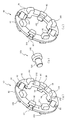
- (A) is a perspective view of a hub
- (b) is a front view of a hub.
- (A) is a perspective view of a clutch ring
- (b) is a perspective view of the pin which comprises a convex part
- (c) is a perspective view of the clutch ring with which the pin was assembled
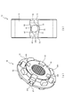
- (A) is a perspective view of the hub with which the clutch ring was assembled
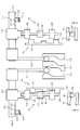
- (b) is a front view of a groove part and a convex part. It is a mimetic diagram of a transmission at the time of low speed coast driving. It is a schematic diagram of the transmission during low-speed drive driving.
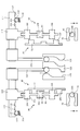
- FIG. 1 is a skeleton diagram of a transmission 1 according to the first embodiment.
- the transmission 1 includes a first shaft 2 (drive shaft) to which power is input, and a second shaft 3 (output shaft) disposed in parallel with the first shaft 2, and an output gear 4 on the second shaft 3. Is arranged.
- the first shaft 2 and the second shaft 3 support a first speed gear 10, a second speed gear 20, a third speed gear 30, a fourth speed gear 40, a fifth speed gear 50, and a sixth speed gear 60 as a plurality of speed change gears.
- transmission 1 is mounted on an automobile (not shown).
- the first speed gear 10 includes a drive gear 11 fixed to the first shaft 2 so as not to rotate relative to the first shaft 2, and a driven gear 12 meshed with the drive gear 11 and fixed to the second shaft 3 so as to be rotatable relative to the second shaft 3.
- the gear 20 includes a drive gear 21 fixed to the first shaft 2 so as to be relatively rotatable, and a driven gear 22 meshed with the drive gear 21 and fixed to the second shaft 3 so as not to be relatively rotatable.
- the third speed gear 30 includes a drive gear 31 fixed to the first shaft 2 so as not to rotate relative to the first shaft 2, and a driven gear 32 engaged with the drive gear 31 and fixed to the second shaft 3 so as to be rotatable relative to the first shaft 2.
- the gear 40 includes a drive gear 41 that is fixed to the first shaft 2 so as to be relatively rotatable, and a driven gear 42 that is meshed with the drive gear 41 and is fixed to the second shaft 3 so as not to be relatively rotatable.
- the fifth speed gear 50 includes a driving gear 51 fixed to the first shaft 2 so as to be relatively rotatable, and a driven gear 52 meshed with the driving gear 51 and fixed to the second shaft 3 so as not to be relatively rotatable.
- the gear 60 includes a drive gear 61 fixed to the first shaft 2 so as to be relatively rotatable, and a driven gear 62 meshed with the drive gear 61 and fixed to the second shaft 3 so as not to be relatively rotatable.
- the hub 70 is a member fixed to the second shaft 3 between the driven gears 12 and 32, the first shaft 2 between the drive gears 21 and 51, and the first shaft 2 between the drive gears 41 and 61 so as not to be relatively rotatable. is there.
- the driven gears 12 and 32 and the drive gears 21, 41, 51, and 61 are provided with teeth (dog teeth) 106 and 107 (see FIG. 5) that protrude in the axial direction on end surfaces in the axial direction.
- the clutch ring 90 is a member that is attached to the hub 70 so as to be relatively movable in the axial direction while engaging with the hub 70, and has teeth (dog teeth, first teeth 95, and first teeth) protruding in the axial direction on the end surface in the axial direction.
- the operation unit 110 is a device for selectively moving the clutch ring 90 in the axial direction, and is coupled to the shift forks 111, 112, 113 respectively engaged with the clutch ring 90 and the shift forks 111, 112, 113.
- the concavo-convex member 114 and the shift arms 120, 121, and 122 respectively coupled to the concavo-convex member 114 are provided.
- the concavo-convex member 114 is a member that applies an urging force in the axial direction to the clutch ring 90 via the shift forks 111, 112, 113, and the concave portions 115, 116, 117 that are recessed in a hemispherical shape are axial directions (the left-right direction in FIG. 1). ).
- the recesses 115, 116, and 117 are portions where the ball 118 urged toward the concavo-convex member 114 by a spring (coil spring) 119 fixed to the case C is elastically engaged.
- the ends of the shift arms 120, 121, 122 are engaged with shift grooves 124, 125, 126 formed on the outer periphery of a columnar shift drum 123 fixed to the case C.
- the shift drum 123 is rotated about its axis by a motor (not shown) based on an operation signal of a shift lever (not shown) or based on an accelerator opening and a vehicle speed signal by operating an accelerator pedal (not shown). Driven.
- the shift drum 123 is rotationally driven, the shift forks 111, 112, 113 are selectively driven in the axial direction via the shift arms 120, 121, 122 guided by the shift grooves 124, 125, 126.
- the clutch ring 90 moves in the axial direction by driving the shift forks 111, 112, and 113.
- the concave-convex member 114 corresponds to the meshing position (first position) at which the concave portions 116, 117 are coupled with any one of the driven gears 12, 32, the drive gears 21, 41, 51, 61 and the clutch ring 90,
- the position 115 corresponds to a neutral position (second position) where any one of the driven gears 12 and 32 and the drive gears 21, 41, 51 and 61 and the clutch ring 90 are separated.
- the ball 118 is elastically engaged with one of the recesses 115, 116, and 117, and the clutch ring 90 is positioned at the first position (engagement position) or the second position (neutral position) in the axial direction.
- FIG. 2A is a perspective view of the hub 70
- FIG. 2B is a front view of the hub 70
- the hub 70 is a cylindrical member in which a spline coupled to the first shaft 2 or the second shaft 3 (see FIG. 1) is formed on the inner peripheral surface 71.
- Grooves 73 are formed at equal intervals at four locations in the circumferential direction.
- the groove portion 73 is a portion that is formed along the axial direction and that is recessed in the radial direction.
- the first wall 74 and the second wall 75, the first wall 74, and the first wall 74 that face each other at an interval in the circumferential direction. 2 and a bottom portion 76 connected to the wall 75.
- the first wall 74 includes a first portion 77 inclined downward in the circumferential direction (in a direction away from the second wall 75) from the outer side in the axial direction toward the central portion 78. And a third portion 79 connected to the outer side of the portion 77 in the axial direction.
- the first portion 77 is an inclined surface inclined with respect to the axial direction
- the third portion 79 is a flat surface parallel to the axial direction.
- the second wall 75 is connected to the second portion 80 that is inclined upward in the circumferential direction (toward the first wall 74) from the outer side in the axial direction toward the central portion 81, and the outer side in the axial direction of the second portion 80.
- a guide portion 82 that is inclined downward in the circumferential direction (in the direction away from the first wall 74) from the outer side in the axial direction toward the second portion 80.
- the second portion 80 and the guide portion 82 are inclined surfaces having different inclination directions with respect to the axial direction.
- the guide portion 82 faces the third portion 79 in the circumferential direction (rotation direction), and the second portion 80 faces the first portion 77 in the circumferential direction (rotation direction).
- the boundary 83 between the second portion 80 and the guide portion 82 has the same axial position (the left-right direction in FIG. 2B) as the axial position of the boundary 84 between the first portion 77 and the third portion 79. Is set.
- FIG. 3A is a perspective view of the clutch ring 90
- FIG. 3B is a perspective view of the pin 103 constituting the convex portion 105
- FIG. 3C is a clutch ring 90 with the pin 103 assembled thereto
- FIG. 4A is a perspective view of the hub 70 to which the clutch ring 90 is assembled
- FIG. 4B is a front view of the groove 73 and the convex portion 105.
- the clutch ring 90 includes an annular ring main body 91, and a plurality of first teeth 95 and second teeth protruding from the axial end surface of the ring main body 91 toward both sides in the axial direction. 100 (dog teeth).
- the ring body 91 is provided with notches 93 that are notched radially inward from four locations on the outer peripheral surface 92 at equal intervals in the circumferential direction.
- An inner diameter of the inner peripheral surface 94 of the ring body 91 is formed to be slightly larger than an outer diameter of the outer peripheral surface 72 of the hub 70 (see FIG. 2A).
- the first teeth 95 are provided between the circular inner peripheral surface 94 of the ring main body 91 and the bottom of the notch 93, and the tooth thickness (circumferential thickness) of the tooth tip (axial tip).
- the end surface 96 in the circumferential direction is an inclined surface that is inclined from the tooth tip toward the tooth root (inner side in the axial direction) so as to make the tooth thickness of the tooth root smaller.
- the ring body 91 is formed with a hole 99 extending in the radial direction so as to penetrate between the radially outer end surface 97 of the first tooth 95 and the radially inner end surface 98 and the inner peripheral surface 94.
- the inner peripheral surface 94 of the ring main body 91 and the end surface 97 of the first tooth 95 are disposed on the same plane.
- the second teeth 100 are alternately arranged with the first teeth 95 at four positions between the first teeth 95 provided at four positions in the circumferential direction of the ring main body 91.
- the circumferential end face 101 is smaller from the tooth tip (axis) than the tooth thickness (circumferential thickness) of the tooth tip (tip in the axial direction).
- the inclined surface is inclined toward the inside of the direction).
- the length of the second tooth 100 from the tooth root to the tooth tip (the length protruding in the axial direction) is set to be larger than that of the first tooth 95.
- the inner peripheral surface 94 of the ring body 91 and the radially inner end surface 102 of the second tooth 100 are disposed on the same plane.
- the pin 103 protrudes from the end portion of the shaft portion 104 to the outer side in the radial direction of the shaft portion 104 and fits into the hole portion 99 formed in the ring main body 91.
- a convex portion 105 a convex portion 105.
- the shaft portion 104 is formed in a cylindrical shape whose length is set to be substantially the same as the length of the hole 99.
- the convex portion 105 has an axial length (thickness) smaller than the height of the first wall 74 and the second wall 75 of the hub 70 (see FIG. 2A), and the radial size is the first size. It is formed in a columnar shape that is set smaller than the interval between the wall 74 and the second wall 75.
- the clutch ring 90 protrudes from the inner peripheral surface 94 side of the ring main body 91 into the hole 99 to project the end surface 98 of the first tooth 95.
- the part 105 is fixed. Since the convex portion 105 is disposed inside the ring body 91 in the radial direction, the convex portion 105 also serves to prevent the pin 103 from coming off. Since the clutch ring 90 is manufactured by fitting the pin 103 into the hole 99 of the ring main body 91, the processing of the clutch ring 90 can be simplified as compared with the case where the convex portion 105 is provided integrally with the ring main body 91.
- the hole 99 is formed at the position of the first tooth 95 in the clutch ring 90, the diameter of the hole can be increased compared to the case where the hole 99 is formed at a position other than the first tooth 95 or the second tooth 100. 104 can be thickened. Since the strength of the shaft 104 fitted in the hole 99 can be increased, the durability of the clutch ring 90 can be improved.
- the clutch ring 90 is mounted on the outer peripheral surface 72 of the hub 70 by inserting the convex portion 105 into the groove 73 of the hub 70 from the axial direction. As shown in FIG. 4B, the convex portion 105 is disposed between the first wall 74 and the second wall 75. The first wall 74 and the second wall 75 come into contact with the convex portion 105, and the hub 70 and the clutch ring 90 rotate together.
- the clutch ring 90 also serves as a tooth (second tooth 100) as a support portion that prevents the hub 70 from falling over, the processing of the clutch ring 90 can be simplified as compared with the case where a support portion is provided separately from the teeth. Since the second tooth 100 has a larger length protruding in the axial direction than the first tooth 95, the ring with respect to the hub 70 is compared with the case where the first tooth 95 having a small length protruding in the axial direction is also used as the support portion. The support length of the main body 91 can be increased. By using the second teeth 100, it is possible to improve the stability when the clutch ring 90 is moved in the axial direction with respect to the hub 70 as compared with the case where the first teeth 95 are used.
- the number of the first teeth 95 is the same as the number of the second teeth 100, and the protrusions 105 protrude from the position of the first teeth 95 in the radial direction of the ring body 91. Since both the function of rotating the hub 70 and the clutch ring 90 by the convex portion 105 and the function of preventing the fall by the second teeth 100 can be achieved, the reliability of the transmission 1 can be ensured.
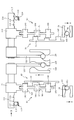
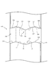
- FIG. 5 is a schematic diagram of the transmission 1 during coasting at a low speed (fourth gear 40)
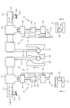
- FIG. 6 is a schematic diagram of the transmission 1 during driving at a low speed (fourth gear 40). 5 to 9, the rotation directions of the drive gears 41 and 51, the hub 70, and the clutch ring 90 are downward (arrow R direction) along the paper surface.
- the shift fork 112 approaches the drive gear 41 of the fourth speed gear 40 by the shift groove 125 and the shift arm 121 of the shift drum 123, and the first teeth 95 and second teeth of the clutch ring 90. 100 meshes with the teeth 106 of the drive gear 41.
- the ball 118 engages with the recess 117 of the uneven member 114 (first position).
- the neutral position (second position) where the ball 118 engages with the recess 115 of the concavo-convex member 114 is maintained, and the clutch ring 90 and the drive gear 51 are separated.
- the clutch ring 90 rotates faster than the hub 70, so that the convex portion 105 has the third portion 79 of the hub 70. Abut. Since the third portion 79 is a flat surface along the axial direction, no axial thrust component is generated at the convex portion 105 (clutch ring 90). Therefore, the meshing between the clutch ring 90 and the drive gear 41 is maintained. Since the end surfaces 96 and 101 in the circumferential direction of the first teeth 95 and the second teeth 100 and the teeth 106 of the drive gear 41 rub against each other, the inclined surfaces that incline from the tooth tip toward the tooth root rub against each other. .
- the hub 70 rotates faster than the clutch ring 90 during driving when power is transmitted from the drive gear 41 to the driven gear 42 (see FIG. 1). 82 abuts. Since the guide portion 82 is inclined with respect to the axial direction and is inclined downward in the circumferential direction toward the second portion 80, an axial force toward the second portion 80 acts on the convex portion 105 (clutch ring 90). Since there is an axial play (gap) G (see FIG. 5) between the shift groove 125 and the shift arm 121, the clutch ring 90 moves in the direction away from the drive gear 41. The convex portion 105 of the clutch ring 90 is in contact with the guide portion 82 and the second portion 80. On the other hand, in the fifth gear 50, the hub 70 rotates faster than the clutch ring 90, so that the convex portion 105 abuts against the central portion 81 of the second wall 75 of the hub 70.
- the concavo-convex member 114 moved in the axial direction as the clutch ring 90 moves pushes the ball 118 by the concave portion 117, compresses the spring 119, and stores elastic energy.
- the spring 119 applies an urging force in the axial direction (arrow B direction) that deepens the engagement with the drive gear 41 to the clutch ring 90.
- the end faces 96 and 101 in the circumferential direction of the first teeth 95 and the second teeth 100 and the teeth 106 of the drive gear 41 are rubbed with each other, the inclined surfaces that are inclined from the tooth tip toward the tooth base rub against each other. To prevent.
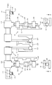
- FIG. 7 is a schematic diagram of the transmission 1 in the middle of shifting from the low speed stage (fourth gear 40) to the high speed stage (fifth gear 50), and FIG. 8 shows the state of the transmission 1 immediately after shifting from the low speed stage to the high speed stage.
- FIG. 9 is a schematic diagram, and FIG. 9 is a schematic diagram of the transmission 1 during drive traveling at a high speed (5-speed gear 50).
- the arrow S shown in FIGS. 7 and 8 is the direction of rotation when the shift drum 123 is shifted up.
- the shift drum 123 is rotated to perform a shift-up operation to the high speed stage (5-speed gear 50).
- the shift fork 113 approaches the drive gear 51 of the fifth speed gear 50 by the shift groove 126 and the shift arm 122 of the shift drum 123, and the tooth tip of the first tooth 95 of the clutch ring 90 contacts the tooth 107 of the drive gear 51. Abuts the tooth tip. Since the second tooth 100 of the clutch ring 90 is longer in the axial direction than the first tooth 95, the second tooth 100 and the tooth 107 of the drive gear 51 can be easily engaged with each other.
- the spring 119 is compressed via the ball 118 by the recess 117 of the concavo-convex member 114, so that the clutch ring 90 and the drive gear 41 are kept engaged.
- the driving gear 51 of the fifth speed gear 50 and the clutch ring 90 are engaged (the teeth 107 and the second teeth 100). Since the 5th gear 50 rotates faster than the 4th gear 40, the 4th speed side is in the coast state and the 5th speed side is in the drive state due to the internal circulation torque. In the fifth speed gear 50, the convex portion 105 abuts on the second portion 80 of the hub 70, and an axial force in which the clutch ring 90 is deeply engaged with the drive gear 51 acts on the convex portion 105.
- the relative rotation between the hub 70 and the clutch ring 90 causes the convex portion 105 contacting the second portion 80 and the guide portion 82 to move toward the first wall 74 side.
- the convex part 105 contacts.
- an axial force that releases the meshing with the drive gear 41 by moving the clutch ring 90 in the neutral direction acts on the convex portion 105. Due to this thrust force, the clutch ring 90 moves in the neutral direction.
- the convex portion 105 When driving, in which power is transmitted from the drive gear 51 to the driven gear 52 (see FIG. 1), the convex portion 105 contacts the guide portion 82 of the hub 70. Since the guide portion 82 is inclined with respect to the axial direction and is inclined downward in the circumferential direction toward the second portion 80, an axial force toward the second portion 80 acts on the convex portion 105 (clutch ring 90). Since there is an axial play (gap) G between the shift groove 125 and the shift arm 121, the clutch ring 90 moves in the direction away from the drive gear 51 by that amount. The convex portion 105 of the clutch ring 90 is in contact with the guide portion 82 and the second portion 80.
- the concavo-convex member 114 pushes the ball 118 by the recess 117 and compresses the spring 119 to store elastic energy.
- the spring 119 applies an urging force in the axial direction (arrow B direction) that deepens the engagement with the drive gear 51 to the clutch ring 90.
- the axial force from the meshing position (first position) to the neutral position (second position) of the clutch ring 90 is applied to the convex portion 105 by the guide portion 82 provided on the hub 70.
- the clutch ring 90 is separated from the transmission gear such as the fourth gear 40 in the axial direction by the length of the guide portion 105 in the axial direction. .
- the shift from the low speed stage to the high speed stage can be brought into a standby state, so that a shock during the shift can be suppressed.
- the guide portion 82 can be formed when the first wall 74 and the second wall 75 are processed and the groove portion 73 is provided in the hub 70, it is possible to suppress an increase in the number of processing steps for parts to provide the guide portion 82. In addition, it is possible to eliminate the need to provide a slope at the tooth base of the clutch ring 90. Therefore, it is possible to simplify the machining of the parts while eliminating the torque interruption at the time of shifting.
- the projecting portion 105 abuts on the second portion 80 of the second wall 75 during drive travel in which power is transmitted from the drive gear 41 to the driven gear 42. Since the second portion 80 faces the first portion 77 in the rotational direction (circumferential direction) and is connected to the guide portion 82, the convex portion 105 moved to the second portion 80 by the guide portion 82 is moved from the second portion 80.
- the clutch ring 90 and the fourth speed gear 40 can be separated.
- the clutch ring 90 and the fourth speed gear 40 are separated, the shift to the high speed stage (fifth speed gear 50) is performed, so that the shift can be performed smoothly.
- the projecting portion 105 abuts against the guide portion 82 and the second portion 80 during drive travel in which power is transmitted from the drive gears 41, 51 to the driven gears 42, 52. Therefore, compared to the case where the guide portion 82 and the second portion 80 are provided in the axial direction at a distance so that the convex portion 105 can move between the guide portion 82 and the second portion 80 during driving, the second portion 80 is provided.
- the axial length of the wall 75 that is, the axial length of the hub 70 can be shortened. As a result, the axial length of the transmission 1 in which a plurality of hubs 70 are arranged can be shortened.
- the clutch ring 90 In the transmission 1, when the clutch ring 90 is moved closest to the drive gears 41 and 51 (transmission gears) by the operation unit 110, the position of the projection 105 in the axial direction (the ball 118 is in the recess 117 of the projection / depression member 114).
- the engaging position is set to be the same as the axial position of the guide portion 82.
- an axial biasing force from the neutral position (second position) to the meshing position (first position) of the clutch ring 90 is applied by the spring 119 to the clutch ring 90. To be granted.
- the transmission gear (4 An axial force that makes it difficult to separate the clutch ring 90 from the high speed gear 40) can be applied to the convex portion 105 (clutch ring 90). Therefore, gear loss can be prevented.
- the convex portion 105 abuts on the third portion 79 of the first wall 74 during coasting in which power is transmitted from the driven gear 42 to the drive gear 41. Since the third portion 79 is connected to the first portion 77 and faces the guide portion 82 in the rotational direction (circumferential direction), the convex portion 105 abuts on the guide portion 82 during driving traveling, and the third portion during coast traveling. 79 abuts. Therefore, it is possible to smoothly switch between driving and coasting.
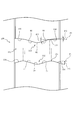
- FIG. 10 is a partially enlarged view of the hub 130 used in the transmission according to the second embodiment.
- the illustration of the circumferential direction of the hub 130 is omitted.
- the hub 130 is arranged in place of the hub 70 of the transmission 1 described in the first embodiment.
- the hub 130 is a cylindrical member coupled to the first shaft 2 or the second shaft 3 (see FIG. 1), and a groove 131 along the axial direction is formed on the outer periphery.
- the groove 131 is a portion that is recessed in the radial direction, and includes a first wall 132 and a second wall 133 that are opposed to each other with an interval in the circumferential direction.
- the first wall 132 includes a first holding portion 134 (third portion) connected to the outer side in the axial direction of the first portion 77 that is inclined downward in the circumferential direction from the outer side in the axial direction toward the central portion 78. .
- the first holding portion 134 is a surface that intersects the axial direction.
- the first holding portion 134 moves in the circumferential direction from the boundary 135 between the first portion 77 and the third portion 134 toward the outside in the axial direction. 2) inclining downward (in the direction away from the wall 133).
- an angle ⁇ 1 formed by a plane P1 parallel to the axis and passing through the boundary 135 between the first portion 77 and the first holding part 134 and the first holding part 134 is 0 ° ⁇ 1 ⁇ 90 °.
- the second wall 133 includes a second holding portion 136 that is connected to the outer side in the axial direction of the second portion 80 and is inclined downward in the circumferential direction (in a direction away from the first wall 132) toward the outer side in the axial direction. ing.
- the second portion 80 and the second holding portion 136 are inclined surfaces having different inclinations with respect to the axial direction.
- An angle ⁇ 2 formed between the plane P2 and the second portion 80 parallel to the axis and passing through the boundary 137 between the second portion 80 and the second holding portion 136 is greater than an angle ⁇ 3 formed between the plane P2 and the second holding portion 136. It is set large ( ⁇ 2> ⁇ 3).
- the formed angle ⁇ 3 is set to 0 ° ⁇ 3 ⁇ 90 °.
- the axial position of the boundary 137 between the second portion 80 and the second holding portion 136 is set to the inner side in the axial direction (the center portion) than the axial position of the boundary 135 between the first portion 77 and the first holding portion 134. 78, 81).
- the hub 130 has a convex portion 105 on the first holding portion 134 (outside in the axial direction from the boundary 135) during coasting (see FIG. 5) in which power is transmitted from the driven gear 42 (see FIG. 1) to the drive gear 41.
- the convex portion 105 can be prevented from moving to the first portion 77 beyond the boundary 135. As a result, it is possible to prevent the clutch ring 90 from moving out in the neutral direction and from being disengaged from the drive gear 41.
- first holding portion 134 is provided on the first wall 132 in conjunction with the processing of the groove portion 131, gear disengagement during coasting can be prevented.
- gear disengagement the gears of the transmission gear 41 and the like and the teeth of the clutch ring 90 can be prevented.
- Processing such as providing a slope on the first teeth 95 and the second teeth 100 can be made unnecessary. Therefore, it is possible to simplify the processing of components (such as the drive gear 41 and the clutch ring 90) while preventing gear loss during coasting.
- the hub 130 has a convex portion 105 on the second holding portion 136 (on the outer side in the axial direction from the boundary 137) during driving (see FIG. 6) in which power is transmitted from the drive gear 41 to the driven gear 42 (see FIG. 1). Abut. Since the second holding portion 136 is formed on an inclined surface that is inclined downward with respect to the plane P2, the convex portion 105 moves beyond the boundary 137 to the second portion 80 during driving (except during shifting). Can be prevented. As a result, it is possible to prevent the clutch ring 90 from moving out in the neutral direction and from being disengaged from the drive gear 41. Since the second holding portion 136 is an inclined surface ( ⁇ 3 ⁇ 90 °) that is inclined downward with respect to the plane P2, a thrust force toward the drive gear 41 acts on the convex portion 105 by the drive torque. Can be increased.
- the angle ⁇ 2 formed by the plane P2 and the second portion 80 is set to be larger than the angle ⁇ 3 formed by the plane P2 and the second holding part 136.
- the portion 105 mainly abuts near the boundary 137 between the second portion 80 and the second holding portion 136 whose inclination with respect to the axial direction changes.
- the hub 130 is provided such that the boundary 137 between the second portion 80 and the second holding portion 136 is located closer to the central portions 78 and 81 than the boundary between the first portion 77 and the first holding portion 134.
- the axial direction of the convex portion 105 when the clutch ring 90 is moved closest to the transmission gear (the drive gear 41, the driven gear 41, etc.) by the operation unit 110 (see FIG. 1). Is set to be the same as the position of the first holding part 134 in the axial direction.
- an axial direction (arrow) from the neutral position (second position) to the mesh position (first position) is detected by the spring 119 of the operation unit 110. The urging force in the B direction is applied to the clutch ring 90.
- the transmission gear (4 An axial force that makes it difficult to separate the clutch ring 90 from the high speed gear 40) can be applied to the convex portion 105 (clutch ring 90). Therefore, it is difficult to cause gear loss.
- FIG. 11 is a partially enlarged view of the hub 140 used in the transmission according to the third embodiment. In FIG. 11, the illustration of the hub 140 in the circumferential direction is omitted. The hub 140 is arranged in place of the hub 70 of the transmission 1 described in the first embodiment.
- the hub 140 is a cylindrical member coupled to the first shaft 2 or the second shaft 3 (see FIG. 1), and a groove portion 141 along the axial direction is formed on the outer periphery.
- the groove portion 141 is a portion that is recessed in the radial direction, and includes a first wall 132 and a second wall 142 that are opposed to each other at an interval in the circumferential direction.
- the second wall 142 is connected to the second portion 143 that rises in the circumferential direction (toward the first wall 132) from the outer side in the axial direction toward the central portion 144, and to the outer side in the axial direction of the second portion 143.
- the second holding portion 145 is inclined downward in the circumferential direction (in the direction away from the first wall 132) from the inner side to the outer side in the axial direction, and is connected to the outer side in the axial direction of the second holding portion 145.
- a guide portion 146 that is inclined upward in the circumferential direction toward the outside in the axial direction.
- the second portion 143 and the second holding portion 145 are inclined surfaces having different inclinations with respect to the axial direction.
- An angle formed between a plane (not shown) parallel to the axis and passing through the boundary 147 between the second portion 143 and the second holding portion 145 and the second portion 143 is formed by the plane and the second holding portion 145. It is set larger than the corner.
- An angle formed by the plane and the second holding portion 145 is set to 0 ° to 90 °.
- the axial position of the boundary 147 between the second portion 143 and the second holding portion 145 is more axially inner than the axial position of the boundary 135 between the first portion 77 and the first holding portion 134 (the central portion). 78, 144).
- the axial position of the boundary 148 between the second holding portion 145 and the guide portion 146 is set to be the same as the axial position of the boundary 135 between the first portion 77 and the first holding portion 134.
- the hub 140 is configured so that the convex portion 105 abuts on the first holding portion 134 and the driven gear 41 moves from the driven gear 41 during coast travel (see FIG. 5) in which power is transmitted from the driven gear 42 (see FIG. 1) to the driving gear 41.
- the convex portion 105 contacts the guide portion 146 that faces the first holding portion 134. Since the guide portion 146 is an inclined surface that is inclined downward toward the second holding portion 145, the protruding portion 105 moves to the second holding portion 145 beyond the boundary 148 due to the thrust force acting on the protruding portion 105.
- the shift from the low speed stage to the high speed stage can be brought into a standby state, so that a shock during the shift can be suppressed.
- the convex portion 105 can be prevented from moving toward the central portion 144 during driving (except during shifting). Since the thrust force in the direction in which the clutch ring 90 and the drive gear 41 (transmission gear) mesh with each other is applied to the convex portion 105 by the second holding portion 136, the clutch ring 90 moves in the neutral direction and meshes with the drive gear 41. It can prevent the gear from coming off.
- the second holding portion 145 on the second wall 142 in conjunction with the processing of the groove portion 141, it is possible to prevent the gear from slipping off during driving, and the guide portion 146 at the time of processing is formed on the second wall 142, so that the gear slipping out.
- it is possible to eliminate the need for processing such as providing inclined surfaces on the gears such as the drive gear 41 and the teeth of the clutch ring 90 (the first teeth 95 and the second teeth 100). Therefore, it is possible to simplify the processing of components (such as the drive gear 41 and the clutch ring 90) while preventing gear disengagement during driving.
- the present invention has been described above based on the embodiments. However, the present invention is not limited to the above embodiments, and various improvements and modifications can be made without departing from the spirit of the present invention. It can be easily guessed.
- the number of gear stages of the transmission 1, the number of groove portions 73, 131, 141 and the convex portion 105, the number of first teeth 95 and the second teeth 100, and the like can be set as appropriate.
- the transmission 1 is mounted on an automobile.
- the present invention is not limited to this, and the transmission 1 can naturally be mounted on a construction machine, an industrial vehicle, an agricultural machine, or the like. is there.
- the transmission 1 can eliminate the torque shortage at the time of shifting. As a result, it is possible to eliminate idle rotation of the first shaft 2 (drive shaft) and improve fuel efficiency.
- the convex portion 105 is formed in a columnar shape (circular in front view) has been described, but the present invention is not necessarily limited thereto. If the convex portion 105 abuts against the walls of the groove portions 73, 131, 141 to generate axial component force (thrust force), a polygonal column shape such as a quadrangular column, a polygonal pyramid shape such as a quadrangular pyramid, a conical shape, etc. It is naturally possible to form the convex portion 105 in a shape other than the cylindrical shape.
- a part or a plurality of parts of the configuration of the other embodiments are added to the embodiment or replaced with a part or a plurality of parts of the configuration of the embodiment.
- the embodiment may be modified and configured.
- the first holding part 134 described in the second embodiment is provided in the hub 70 in the first embodiment
- the second holding part 145 described in the third embodiment is provided in the hub 70 in the first embodiment. It can be set as appropriate.
Landscapes
- Engineering & Computer Science (AREA)
- General Engineering & Computer Science (AREA)
- Mechanical Engineering (AREA)
- Mechanical Operated Clutches (AREA)
Abstract
L'invention concerne une transmission qui élimine la perte de couple pendant le changement de vitesse et avec laquelle le traitement de composants peut être simplifié. Une force axiale est générée dans une protubérance (105) au moyen d'une première partie (77) pendant le changement de vitesse d'une vitesse inférieure à une vitesse élevée, et lorsqu'un engrenage de transmission à basse vitesse et une bague d'embrayage (90) se séparent l'un de l'autre, un engrenage de transmission à grande vitesse et la bague d'embrayage (90) se verrouillent. Étant donné que le mouvement relatif de la protubérance (105) dans une direction neutre est supprimé au moyen d'une première partie de retenue (134) en roue libre, il est possible de supprimer le débrayage de l'engrenage permettant aux engrenages de transmission et à la bague d'embrayage (90) de se séparer les uns des autres. Étant donné que la première partie de retenue (134) peut être formée dans une première paroi (132) lors de la fourniture d'une partie de rainure (131), il est possible de supprimer une augmentation de la charge de travail de traitement de composants.
Priority Applications (4)
| Application Number | Priority Date | Filing Date | Title |
|---|---|---|---|
| US15/746,915 US10968960B2 (en) | 2015-07-24 | 2015-07-24 | Transmission |
| JP2017530469A JP6503068B2 (ja) | 2015-07-24 | 2015-07-24 | 変速機 |
| EP15899558.9A EP3327305B1 (fr) | 2015-07-24 | 2015-07-24 | Transmission |
| PCT/JP2015/071093 WO2017017724A1 (fr) | 2015-07-24 | 2015-07-24 | Transmission |
Applications Claiming Priority (1)
| Application Number | Priority Date | Filing Date | Title |
|---|---|---|---|
| PCT/JP2015/071093 WO2017017724A1 (fr) | 2015-07-24 | 2015-07-24 | Transmission |
Publications (1)
| Publication Number | Publication Date |
|---|---|
| WO2017017724A1 true WO2017017724A1 (fr) | 2017-02-02 |
Family
ID=57884314
Family Applications (1)
| Application Number | Title | Priority Date | Filing Date |
|---|---|---|---|
| PCT/JP2015/071093 Ceased WO2017017724A1 (fr) | 2015-07-24 | 2015-07-24 | Transmission |
Country Status (4)
| Country | Link |
|---|---|
| US (1) | US10968960B2 (fr) |
| EP (1) | EP3327305B1 (fr) |
| JP (1) | JP6503068B2 (fr) |
| WO (1) | WO2017017724A1 (fr) |
Cited By (2)
| Publication number | Priority date | Publication date | Assignee | Title |
|---|---|---|---|---|
| JP2020012475A (ja) * | 2018-07-13 | 2020-01-23 | 株式会社ユニバンス | 変速機 |
| US10883547B2 (en) * | 2017-03-22 | 2021-01-05 | Kabushiki Kaisha Toyota Chuo Kenkyusho | Dog clutch and transmission |
Families Citing this family (2)
| Publication number | Priority date | Publication date | Assignee | Title |
|---|---|---|---|---|
| EP4234983B1 (fr) * | 2021-03-02 | 2025-08-06 | Univance Corporation | Transmission |
| WO2023238316A1 (fr) * | 2022-06-09 | 2023-12-14 | ヤマハ発動機株式会社 | Dispositif de transmission |
Citations (1)
| Publication number | Priority date | Publication date | Assignee | Title |
|---|---|---|---|---|
| JP2012127471A (ja) * | 2010-12-17 | 2012-07-05 | Ikeya Formula Kk | トランスミッション |
Family Cites Families (5)
| Publication number | Priority date | Publication date | Assignee | Title |
|---|---|---|---|---|
| DE9408943U1 (de) * | 1994-06-01 | 1994-07-21 | INA Wälzlager Schaeffler KG, 91074 Herzogenaurach | Synchronisiereinrichtung für Schaltgetriebe |
| US5651435A (en) * | 1995-07-31 | 1997-07-29 | New Venture Gear, Inc. | Reverse brake for manual transmissions |
| WO2012066740A1 (fr) * | 2010-11-19 | 2012-05-24 | 株式会社イケヤフォーミュラ | Transmission et système de commande des changements de rapport |
| WO2013190126A1 (fr) * | 2012-06-22 | 2013-12-27 | Drive System Design | Système de transmission |
| JP5790701B2 (ja) * | 2013-04-15 | 2015-10-07 | 株式会社豊田中央研究所 | クラッチ機構及び変速機 |
-
2015
- 2015-07-24 US US15/746,915 patent/US10968960B2/en not_active Expired - Fee Related
- 2015-07-24 WO PCT/JP2015/071093 patent/WO2017017724A1/fr not_active Ceased
- 2015-07-24 EP EP15899558.9A patent/EP3327305B1/fr not_active Not-in-force
- 2015-07-24 JP JP2017530469A patent/JP6503068B2/ja not_active Expired - Fee Related
Patent Citations (1)
| Publication number | Priority date | Publication date | Assignee | Title |
|---|---|---|---|---|
| JP2012127471A (ja) * | 2010-12-17 | 2012-07-05 | Ikeya Formula Kk | トランスミッション |
Cited By (2)
| Publication number | Priority date | Publication date | Assignee | Title |
|---|---|---|---|---|
| US10883547B2 (en) * | 2017-03-22 | 2021-01-05 | Kabushiki Kaisha Toyota Chuo Kenkyusho | Dog clutch and transmission |
| JP2020012475A (ja) * | 2018-07-13 | 2020-01-23 | 株式会社ユニバンス | 変速機 |
Also Published As
| Publication number | Publication date |
|---|---|
| JPWO2017017724A1 (ja) | 2018-05-10 |
| EP3327305A4 (fr) | 2019-04-17 |
| US10968960B2 (en) | 2021-04-06 |
| EP3327305A1 (fr) | 2018-05-30 |
| EP3327305B1 (fr) | 2020-09-02 |
| JP6503068B2 (ja) | 2019-04-17 |
| US20200088241A1 (en) | 2020-03-19 |
Similar Documents
| Publication | Publication Date | Title |
|---|---|---|
| CN108006096B (zh) | 牙嵌式离合器 | |
| JP6438292B2 (ja) | 車両用変速機 | |
| WO2017017724A1 (fr) | Transmission | |
| JP5956805B2 (ja) | 変速機 | |
| JP4875302B2 (ja) | ドグクラッチ | |
| JP6590569B2 (ja) | 変速機 | |
| US9188169B2 (en) | Shift device with synchronizer | |
| JP5909135B2 (ja) | 変速機 | |
| JP6503067B2 (ja) | 変速機 | |
| JP5860330B2 (ja) | 変速機 | |
| JP5439555B2 (ja) | 変速機 | |
| JP6750166B2 (ja) | 自動変速機 | |
| JP7562040B2 (ja) | ドッグクラッチ | |
| JP5254286B2 (ja) | 変速機のフォークシャフトの支持構造 | |
| JP7288975B2 (ja) | 変速機 | |
| JP6669835B2 (ja) | トランスミッション | |
| JP7317321B2 (ja) | 変速機 | |
| JP2020012475A (ja) | 変速機 | |
| JP6248507B2 (ja) | ドグクラッチ式変速装置 | |
| JP7385676B2 (ja) | 変速機 | |
| JP2014105821A (ja) | ワンウェイクラッチおよび無段変速機 | |
| JP7391106B2 (ja) | 変速機 | |
| JP6251102B2 (ja) | 動力伝達装置 | |
| JP2018071627A (ja) | 自動変速機 | |
| JP6716821B2 (ja) | 自動変速機 |
Legal Events
| Date | Code | Title | Description |
|---|---|---|---|
| 121 | Ep: the epo has been informed by wipo that ep was designated in this application |
Ref document number: 15899558 Country of ref document: EP Kind code of ref document: A1 |
|
| ENP | Entry into the national phase |
Ref document number: 2017530469 Country of ref document: JP Kind code of ref document: A |
|
| NENP | Non-entry into the national phase |
Ref country code: DE |