WO2017017732A1 - Récipient d'emballage de véhicule à deux roues - Google Patents
Récipient d'emballage de véhicule à deux roues Download PDFInfo
- Publication number
- WO2017017732A1 WO2017017732A1 PCT/JP2015/071143 JP2015071143W WO2017017732A1 WO 2017017732 A1 WO2017017732 A1 WO 2017017732A1 JP 2015071143 W JP2015071143 W JP 2015071143W WO 2017017732 A1 WO2017017732 A1 WO 2017017732A1
- Authority
- WO
- WIPO (PCT)
- Prior art keywords
- skid
- pair
- wheel holding
- members
- wheel
- Prior art date
- Legal status (The legal status is an assumption and is not a legal conclusion. Google has not performed a legal analysis and makes no representation as to the accuracy of the status listed.)
- Ceased
Links
Images




Classifications
-
- B—PERFORMING OPERATIONS; TRANSPORTING
- B65—CONVEYING; PACKING; STORING; HANDLING THIN OR FILAMENTARY MATERIAL
- B65D—CONTAINERS FOR STORAGE OR TRANSPORT OF ARTICLES OR MATERIALS, e.g. BAGS, BARRELS, BOTTLES, BOXES, CANS, CARTONS, CRATES, DRUMS, JARS, TANKS, HOPPERS, FORWARDING CONTAINERS; ACCESSORIES, CLOSURES, OR FITTINGS THEREFOR; PACKAGING ELEMENTS; PACKAGES
- B65D19/00—Pallets or like platforms, with or without side walls, for supporting loads to be lifted or lowered
- B65D19/38—Details or accessories
- B65D19/44—Elements or devices for locating articles on platforms
-
- B—PERFORMING OPERATIONS; TRANSPORTING
- B65—CONVEYING; PACKING; STORING; HANDLING THIN OR FILAMENTARY MATERIAL
- B65D—CONTAINERS FOR STORAGE OR TRANSPORT OF ARTICLES OR MATERIALS, e.g. BAGS, BARRELS, BOTTLES, BOXES, CANS, CARTONS, CRATES, DRUMS, JARS, TANKS, HOPPERS, FORWARDING CONTAINERS; ACCESSORIES, CLOSURES, OR FITTINGS THEREFOR; PACKAGING ELEMENTS; PACKAGES
- B65D85/00—Containers, packaging elements or packages, specially adapted for particular articles or materials
- B65D85/68—Containers, packaging elements or packages, specially adapted for particular articles or materials for machines, engines or vehicles in assembled or dismantled form
Definitions
- the present invention relates to a packaging container for a motorcycle used for transporting or storing the motorcycle.
- Patent Document 1 discloses a two-wheeled vehicle transport container that fixes a two-wheeled vehicle to a transport pallet by holding a front wheel of the two-wheeled vehicle with a front wheel fixing jig and holding a center stand of the two-wheeled vehicle with a stand fixing means.
- Patent Document 2 discloses a returnable case in which the front wheel of the scooter is dropped between the bars of the front wheel fixing member, and the scooter is fixed so as to straddle the lateral displacement prevention member on the upper surface of the support plate.
- Patent Document 1 a pair of round bars are fixed at four locations on the frame frame, and the front wheel of the motorcycle is inserted between the round bars to regulate the position of the front wheels. Further, the front wheel fixing member described in Patent Document 2 regulates the position of the front wheel by dropping the front wheel between the bars.
- the round bar of the front wheel fixing jig or the bar of the front wheel fixing member is fixed to the pallet or the like, and only the front wheel that falls within the width between the pair of round bars or bars can be held.
- Patent Document 1 or 2 does not disclose a fixing member that restricts the movement of the rear wheel, and the center stand or the lateral slip prevention means holds the vicinity of the rear wheel of the motorcycle. It is difficult to regulate the movement of the rear wheels, and the types of motorcycles that can be held are limited.
- the present invention has been made in view of the above circumstances, and an object of the present invention is to provide a two-wheeled vehicle packaging container on which a plurality of types of two-wheeled vehicles can be mounted using the same skid.
- the packaging container for a motorcycle is: A packaging container for a motorcycle including a skid for mounting the motorcycle on the upper surface, A pair of first wheel holding members that move in the width direction of the wheels of the two-wheeled vehicle placed on the skid and hold the wheels in the width direction; A first moving mechanism for moving the pair of first wheel holding members relative to each other along the width direction of the wheels; A first fixing member for fixing the first wheel holding member to the skid, It is characterized by that.
- a pair of second wheel holding members that move in the traveling direction of the wheels of the two-wheeled vehicle mounted on the skid, and sandwich and hold the outer periphery of the wheels;
- a second moving mechanism for moving the pair of second wheel holding members relative to each other in the traveling direction of the wheels;
- a second fixing member that fixes the second wheel holding member to the skid.
- the skid may have a rectangular shape, and a plurality of the pair of first wheel holding members may be provided along one side of the skid.
- the pair of first wheel holding members may be a pair of rod-shaped members.
- the first moving mechanism includes: A first rail member provided along one side of the skid formed in a rectangular shape;
- the first wheel holding member is provided on at least one of the pair of first wheel holding members, and engages with the first rail member and slides along the first rail member. And a slide member.
- the second moving mechanism includes: A second rail member provided along a side adjacent to one side where the first rail member of the rectangular skid is disposed; A second wheel holding member that is provided on at least one of the pair of second wheel holding members and that slides along the second rail member by engaging with the second rail member; And a slide member.
- the first fixing member is The first wheel holding member may be fixed to the skid with a bolt and a nut.
- the packaging container for a motorcycle is: A packaging container for a motorcycle including a skid for mounting the motorcycle on the upper surface, A pair of wheel holding members that move in the traveling direction of the wheels of the two-wheeled vehicle mounted on the skid and hold the outer peripheral portion of the wheels in a sandwiched manner; A moving mechanism for moving the pair of wheel holding members in the traveling direction of the wheels; A fixing member for fixing the wheel holding member to the skid, It is characterized by that.
- a frame that can be changed between a state of rising with respect to the skid and a state of being folded may be further provided.
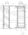
- FIG. 1 is an overall perspective view schematically showing a motorcycle packaging container according to an embodiment of the present invention. It is a top view of the skid of the packaging container for two-wheeled vehicles which concerns on this Embodiment.
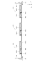
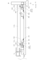
- Fig. 3 is a left sectional view of a skid of the packaging container for a motorcycle shown in Fig. 2.
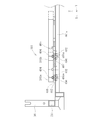
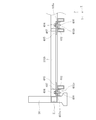
- FIG. 4 is a partially enlarged explanatory view of the skid shown in FIG. 3 cut along the line A-A ′ of FIG. 2.
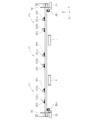
- Fig. 3 is a right side sectional view of a skid of the packaging container for a motorcycle shown in Fig. 2.
- FIG. 6 is a partially enlarged explanatory view of the skid shown in FIG. 5 cut along the line B-B ′ of FIG. 2.
- Fig. 3 is a left sectional view of a skid of the packaging container for a motorcycle shown in Fig. 2.
- FIG. 4 is a partially enlarged explanatory view of the skid shown in FIG. 3 cut along the line
- FIG. 3 is a front sectional view of a skid of the packaging container for a motorcycle shown in Fig. 2.
- FIG. 8 is a partially enlarged explanatory view of the skid shown in FIG. 7 cut along the line C-C ′ of FIG. 2.
- FIG. 8 is a partially enlarged explanatory view of the skid shown in FIG. 7 cut along a line D-D ′ in FIG. 2.
- FIG. 8 is a partially enlarged explanatory view of the skid shown in FIG. 7 cut along line E-E ′ of FIG. 2.
- FIGS. 1 to 10 A motorcycle packaging container according to an embodiment of the present invention will be described with reference to FIGS. 1 to 10, for example, a container for packaging a motorcycle.
- 1 is an overall perspective view of a motorcycle packaging container 1 according to an embodiment of the present invention
- FIG. 2 is a top view of a skid of the motorcycle packaging container 1 according to this embodiment
- FIG. FIG. 2 is a partially enlarged explanatory view of the skid of the illustrated two-wheel packaging container 1 cut along the line BB ′.
- the motorcycle packaging container includes a skid 2 that constitutes the bottom of the motorcycle packaging container 1, and a pair of frame parts 3 that rise from a pair of opposing sides of the skid 2.
- the motorcycle is mounted on the skid 2 and used for storing or transporting the motorcycle.
- XYZ coordinates in which the longitudinal direction of the packaging container 1 for a motorcycle 1 is the X-axis direction, the width direction (depth direction) is the Y-axis direction, and the height direction is the Z-axis direction are described. Set and refer as appropriate.
- the frame portion 3 is provided across a pair of first struts 301 erected in the Z-axis direction above from both ends of one side of the skid 2, and a pair of first struts 301.
- pillar 303, and the connection members 302 and 304 consist of a hollow square material which bent the thin steel plate, for example.
- the connecting members 302 and 304 may be configured by combining rod-shaped square members as in the present embodiment, or may be plate-shaped members. As long as the connection members 302 and 304 can restrict the movement of the two-wheeled vehicle mounted on the skid 2 in the X-axis direction, any configuration may be adopted.
- the first support column 301 and the second support column 303 of the frame unit 3 and the skid 2 are connected by a folding member 305 at each predetermined position.
- the folding member 305 is formed of a metal cylindrical pipe or the like, and one end of the pipe is fixed to the first column 301 or the second column 303 and the other is fixed to the skid 2 by a fastening member. This prevents the first column 301 and the second column 303 standing at the four corners of the skid 2 from being inclined.
- the folding member 305 can be removed by loosening the fastening members that have fixed the first support column 301, the second support column 303, and the skid 2.
- the frame part 3 By removing the folding member 305, the frame part 3 can be tilted with respect to the skid 2, and the frame part 3 is folded on the upper surface of the skid 2.
- the frame portion 3 is erected with respect to the skid 2, and the frame portion 3 and the skid 2 are connected by the folding member 305, whereby the two-wheeled vehicle packaging container 1 can be used.
- the two-wheeled vehicle packaging container 1 shrinks in the vertical direction, so that a plurality of two-wheeled vehicle packaging containers 1 can be stacked in the vertical direction. Therefore, when the motorcycle packaging container 1 is not used, the motorcycle packaging container 1 can be compactly folded and stored in a predetermined storage location.
- the skid 2 is formed of a frame having a rectangular shape in a top view in which four frame members 21, 22, 23, and 24 having predetermined lengths are connected at respective end portions.
- the bottom part of the packaging container 1 is comprised.
- the frame members 21 to 24 are made of, for example, hollow square members obtained by bending thin steel plates.
- support members 36 for standing a pair of first support columns 301 and a pair of second support columns 303 are provided at the four corners of the rectangular skid 2.
- the support member 36 extends a predetermined length from the four corners of the skid 2 in the Z-axis direction, and the upper end portion is opened so that the first support column 301 and the second support column 303 can be inserted.
- the support member 36 is made of, for example, a hollow square material obtained by bending a thin steel plate.
- the skid 2 is provided with a pair of fork guides 4 parallel to the frame member 22 of the skid 2.
- the skid 2 is transported by inserting a fork of a forklift into the fork guide 4.
- the fork guide 4 has a cross-sectional shape into which the fork of the forklift can be inserted, and has a length that allows part or all of the forklift to be inserted.
- the motorcycle packaging container 1 includes a pressing member 6 that holds the motorcycle mounted on the skid 2 from above.
- the pressing member 6 is formed of, for example, a hollow square material obtained by bending a thin steel plate and has substantially the same length as the frame materials 21 and 23.
- a pair of first insertion rings 6a for inserting the belt is provided at both ends.
- a pair of second insertion rings 6b for inserting a belt is also provided at a pair of opposing sides of the skid 2, for example, near the center of the frame members 22 and 24.
- the presser member 6 On the line connecting the pair of second insertion rings 6b, the presser member 6 is lowered from above (Z-axis direction), and the presser member 6 presses the vicinity of the step of the motorcycle.
- the holding member 6 is fixed near the step of the motorcycle through a belt through the first insertion ring 6a and the second insertion ring 6b.
- the belt is not shown, and the presser member 6 disposed in a used position is schematically shown.
- the second insertion ring 6b may be provided at two locations along the frame member 22 so that the motorcycle can be fixed with a belt according to the length of the motorcycle to be mounted. Good.
- a pair of first wheel holding members 100 that hold and hold the width direction of the front or rear wheels of the motorcycle and the outer periphery of the front or rear wheels in the traveling direction of the motorcycle are held and held by the skid 2.
- Two moving mechanisms 500 are arranged.
- FIGS. 3 is a left sectional view of the skid of the packaging container for a motorcycle shown in FIG. 2
- FIG. 4 is a partially enlarged explanatory view of the skid shown in FIG. 3 cut along the line AA ′ in FIG. 2
- FIG. 2 is a right sectional view of the skid of the packaging container for a motorcycle shown in FIG. 2
- FIG. 6 is a partially enlarged explanatory view of the skid shown in FIG. 5 cut along the line BB ′ in FIG. 2
- FIG. 8 is shown in FIG.
- FIG. 3 is a partially enlarged explanatory view of a skid cut along a line CC ′ in FIG. 2.
- the first wheel holding member 100 includes a wheel holding member 101 for a front wheel and a wheel holding member 111 for a rear wheel.
- the wheel holding member 101 for the front wheel is engaged with a pair of first rail members 401 whose both ends are part of the first moving mechanism 400.
- a plurality of front wheel holding members 101 for the front wheels are provided along the frame member 21 of the skid 2, and three in the present embodiment.
- One front wheel holding member 101 is composed of a pair of rod-shaped members 101a and 101b, and the pair of rod-shaped members 101a and 101b holds a front wheel (not shown) sandwiched from the width direction.
- the pair of rod-shaped members 101a and 101b is a member made of a hollow square material obtained by bending a thin steel plate, for example.
- the pair of rod-shaped members 101a and 101b are disposed so as to be inclined with respect to the frame member 21 of the skid 2 when viewed from above, and can hold the front wheel with the handle of the motorcycle locked.
- the first moving mechanism 400 of the wheel holding member 101 for the front wheel includes a pair of first rail members 401 provided along the frame member 21 of the skid 2,
- the first slide members 402 provided at both ends of the first and second rod-shaped members 101a and 101b.
- the pair of rod-shaped members 101a and 101b 101b is moved in the X-axis direction.
- the pair of first rail members 401 includes a rail member 401a provided along the frame member 21 of the skid 2, and a rail member 401b disposed in parallel with the rail member 401a at a predetermined interval.
- the rail member 401a and the rail member 401b are arranged with a predetermined interval smaller than the diameter of the front wheel.
- the rail members 401a and 401b extend along the frame material 21 in the X-axis direction of the skid 2, and an opening 403 is formed on the upper surface.
- the rail members 401a and 401b are formed of lip groove steel having a lip groove in cross section. Yes.
- a first slide member 402 is attached by bolts 404 to both ends of each of the pair of rod-like members 101a and 101b.
- the first slide member 402 is a plate-like small piece member that is inserted from the opening 403 of the first rail member 401 and slides in the slide groove of the first rail member 401. Note that the first slide member 402 does not have to be plate-shaped, and various shapes such as a pin shape can be employed.
- the first slide member 402 may be directly attached to both ends of the rod-like members 101a and 101b, or may be attached via a connecting member. In the present embodiment, the rod-shaped members 101 a and 101 b and the first slide member 402 are connected via the connection member 405.
- the connection member 405 is a plate-like small piece member, and one end portion is connected to one end portion of the rod-like members 101a and 101b, and the first slide member 402 is connected to the lower surface of the other end portion.
- the connecting member 405 When the rod-shaped members 101a and 101b and the first slide member 402 are connected via the connecting member 405, the inclination angle of the rod-shaped members 101a and 101b with respect to the frame member 21 can be changed, and the mounted motorcycle The operator can set an arbitrary inclination angle according to the inclination angle of the front wheel.
- the first slide member 402 is a rectangular metal piece having a side longer than the opening width of the opening 403 of the rail members 401a and 401b, and a hole in which a thread groove is formed on the inner periphery. 406.
- the hole 406, the bolt 404, and the nut 407 disposed between the first rail member 401 and the connection member 405 constitute a first fixing member.
- the connection member 405 has a hole 405a into which the bolt 404 is inserted. In order to fix the first slide member 402 to the first rail member 401, first, the first slide member 402 is inserted from the openings 403 of the rail members 401a and 401b.
- the bolt 404 is passed through the hole 405a from above the connecting member 405, and is screwed with a nut 407 interposed between the rail members 401a and 401b and the connecting member 405. Further, the bolt 404 is screwed into the hole 406 of the first slide member 402.
- the first slide member 402 can slide in the rail groove of the first rail member 401, and the first slide member 402 is moved to a predetermined position in the X-axis direction. Can do.
- the rod-shaped members 101a and 101b are fixed at that position.
- the first slide member 402 is fixed to the rail members 401 a and 401 b by the bolt 404 and the nut 407, and the wheel can be reliably fixed to the upper surface of the skid 2.
- the nut 407 of the first fixing member is located between the connection member 405 and the first slide member 402, but is positioned below the first slide member 402. May be. Further, the first fixing member may be composed of only the first slide member 402 and the bolt 404.
- the rod-shaped member 101a and the rod-shaped member 101b are moved along the X-axis direction. It can be moved to any position. Therefore, the operator can change the space
- the rod-shaped members 101a and 101b are fastened to the first rail member 401 by fastening the bolt 404 to the hole 406 and the nut 407 of the first slide member 402. Fixed to.
- the present invention is not limited to this.
- only the first slide member 402 of one rod-like member is slid in the rail groove of the rail members 401a and 401b, and the other rod-like member is fixed on the rail, and the pair of rod-like members 101a, The relative distance between 101b is changed.
- the rail members 401a and 401b are used to move the pair of rod-like members 101a and 101b, but the present invention is not limited to this.
- a slide member that engages with the rail member may be attached in the vicinity of the center of one of the rod-shaped members, and the other rod-shaped member may be fixed to the rail member.
- One rear wheel holding member 111 is composed of a pair of rod-shaped members 111a and 111b, and a pair of rod-shaped members 111a and 111b sandwich and hold a rear wheel (not shown) from the width direction.
- the pair of rod-shaped members 111a and 111b is also a member made of a hollow square material obtained by bending a thin steel plate, for example.
- the first moving mechanism 400 of the wheel holding member 111 for the rear wheel includes a pair of first rail members 411 provided along the frame member 23 of the skid 2, as shown in FIGS. It consists of the 1st slide member 402 provided in the both ends of a pair of rod-shaped member 111a, 111b, and when a 1st slide member 402 slides along the said 1st rail member 411, a pair of rod-shaped member 111a. , 111b are moved in the X-axis direction.
- the pair of first rail members 411 includes a rail member 411b provided along the frame member 23 of the skid 2, and a rail member 411a disposed in parallel with the rail member 411b at a predetermined interval.
- the rail member 411a and the rail member 411b are arranged with a predetermined interval smaller than the diameter of the rear wheel. Further, the rail members 411a and 411b extend along the frame member 23 in the X-axis direction of the skid 2, and an opening 413 is formed on the upper surface. Yes.
- a first slide member 402 is attached to each end of each of the pair of rod-shaped members 111a and 111b by bolts 404.
- the first slide member 402 is a rectangular metal piece having a side longer than the opening width of the opening 413 of the rail members 411a and 411b, and has a hole 406 in which a thread groove is formed on the inner periphery.
- Bolts 404 are screwed into the first slide member 402 to fix the first slide member 402 to the first rail member 411.
- the bolt 404 is loosened, the first slide member 402 can slide in the rail groove of the first rail member 411, and the first slide member 402 is moved to a predetermined position in the X-axis direction. Can do.
- a nut may be attached between the rail members 411 a and 411 b and the first slide member 402 or below the first slide member 402.
- the rod-shaped member 111a and the rod-shaped member 111b are aligned along the X-axis direction. It can be moved to any position. Therefore, the operator can change the space
- the rod-shaped members 111a and 111b are fixed to the first rail member 411 by fastening the bolt 404 to the hole 406 of the first slide member 402.
- the first wheel holding member 100 has been described as having the two first wheel holding members 100, the wheel holding member 101 for the front wheel and the wheel holding member 111 for the rear wheel.
- the wheel holding member 100 may include any one wheel holding member for the front wheel or the rear wheel.
- FIGS. 7 is a front sectional view of the skid of the packaging container for a motorcycle shown in FIG. 2
- FIG. 9 is a partially enlarged explanatory view of the skid shown in FIG. 7 cut along the line DD ′ of FIG. 2
- FIG. FIG. 8 is a partially enlarged explanatory view of the skid shown in FIG. 7 cut along the line EE ′ of FIG. 2.
- the second wheel holding member 200 includes a pair of rod-like members 201a and 201b provided in parallel along the frame member 23 of the skid 2 at a predetermined interval.
- a pair of rod-shaped members 201a and 201b hold a rear wheel (not shown) sandwiched from the traveling direction.
- the pair of rod-shaped members 202a and 202b is a member made of a hollow square material obtained by bending a thin steel plate, for example.
- the second wheel holding member 200 may hold the front wheel with the front wheel interposed therebetween. The configuration in that case is the same as the case where the rear wheel is held between the traveling directions.
- the pair of rod-shaped members 201a and 201b are the same as the rail members 411a and 411b, but may be provided separately from the rail members 411a and 411b.
- the second moving mechanism 500 includes a pair of second rail members 501 provided along the frame members 22 and 24 of the skid 2, and second slides provided at both ends of the pair of rod-like members 201a and 201b. It consists of the member 502, and when the 2nd slide member 502 slides along the 2nd rail member 501, a pair of rod-shaped member 201a, 201b is moved along a Y-axis direction. That is, the pair of rod-shaped members 201a and 201b moves along the traveling direction in which the rear wheel moves when the rear wheel is placed between the pair of rod-shaped members 201a and 201b.
- the second moving mechanism 500 is provided below the first moving mechanism 400. Since the second moving mechanism 500 and the first moving mechanism 400 are provided vertically, the first wheel holding member 100 and the second wheel holding member 200 can be moved independently of each other.
- the pair of second rail members 501 are arranged with a predetermined interval smaller than the diameter of the rear wheel. Further, the second rail member 501 extends along the frame members 22 and 23 in the Y-axis direction of the skid 2, has an opening 503 on the upper surface, and has a lip groove having a cross-sectional shape as a lip groove. It is formed by.
- a second slide member 502 is attached to each end of each of the pair of rod-shaped members 201a and 201b by bolts 504.
- the second slide member 502 is a plate-like small piece member that is inserted from the opening 503 of the second rail member 501 and slides in the slide groove of the second rail member 501.
- the second slide member 502 may be directly attached to both ends of the rod-like members 201a and 201b, or may be attached via a connecting member.
- the rod-shaped members 201a and 201b and the second slide member 502 are connected via the hole 505a of the connecting member 505.
- the connecting member 505 is formed by bending a thin plate, and a hole 505a is formed in the bent portion.
- the second slide member 502 has a hole 506 in which a thread groove is formed on the inner periphery. Then, the bolts 504 are inserted into the holes 505a and 506 and screwed into the thread grooves, whereby the rod-shaped members 201a and 201b are fixed to the second rail member 501. Further, when the bolt 504 is loosened, the second slide member 502 can be slid in the rail groove of the second rail member 501, and the second slide member 502 is moved to a predetermined position in the Y-axis direction. Can do.
- the hole 506 provided in the second slide member 502 and the bolt 504 constitute a second fixing member. Further, as in the first rail member 401, a nut may be attached between the second rail member 501 and the second slide member 502 or below the second slide member 502.
- the rod-shaped members 201a and 201b are positioned at arbitrary positions along the Y-axis direction. Can be moved to. Therefore, the operator can change the space
- the rod-shaped members 201a and 201b are fixed to the second rail member 501 by fastening the bolts 504 into the holes 506 of the second slide member 502.
- the rod-shaped members 201a and 201b can move in the traveling direction of the rear wheel, but the moving direction is the direction in which the interval between the rod-shaped members 201a and 201b is widened or narrowed, that is, in the Y-axis direction on the second rail member 501. It is possible to move in the direction of relatively widening or narrowing the distance between the two. Thereby, since the space
- rod-shaped members 201a and 201b can move in the Y direction, that is, move in the left-right direction on the paper surface of FIG. 2 while keeping the distance between the rod-shaped members 201a and 201b constant. It is also possible to hold the rear wheel depending on the situation.
- the wheel holding member 111 for the rear wheel that holds the width direction of the wheels is the rod-shaped member 201a.
- 201b must have a length corresponding to the interval between them. Therefore, when the interval between the rod-like members 201a and 201b is changed, the wheel holding member 111 for the rear wheel corresponding to the interval is replaced, or the wheel holding member 111 for the rear wheel can be extended and retracted. By doing so, it is possible to provide the wheel holding member 111 for the rear wheel according to the change in the interval.
- the wheel holding member 111 for the rear wheel and the second wheel holding member 200 are overlapped, but the present invention is not limited to this.
- the second rail member 501 has been described as a pair of rail members, one rail member is arranged near the center of the skid 2 and the second slide member 502 of the rod-like members 201a and 201b is attached to the rail. You may slide on a member.
- the operation of holding the width direction of the wheel by the first wheel holding member 100 will be described. Specifically, the operation of holding the width direction of the wheel using the first wheel holding member 100 will be described using the wheel holding member 101 for the front wheel, and the wheel holding member 111 for the rear wheel will be described. Omitted.
- the bolt 404 screwed into the hole 406 of the first slide member 402 is loosened so that the first slide member 402 can move in the first rail member 401.
- the first slide member 402 slides in the rail grooves of the rail members 401a and 401b, and moves the pair of rod-like members 101a and 101b to a position corresponding to the width of the front wheel of the motorcycle mounted on the skid 2.
- the front wheel of the motorcycle is inserted between a pair of rod-shaped members 101a and 101b arranged at a predetermined interval, and the distance between the pair of rod-shaped members 101a and 101b is reduced so as to hold the front wheel.
- the bolt 404 is screwed into the thread of the hole 406 of the first slide member 402, and the first slide member 402 is fixed to the first rail members 401a and 401b.
- the pair of rod-shaped members 101a and 101b move along the rail member 401a from the position indicated by the solid line to the position indicated by the dotted line.
- the pair of rod-like members 101a and 101b move similarly with respect to the rail member 401b.
- the pair of rod-shaped members 101a and 101b move in the X-axis direction while maintaining a constant interval.
- the sliding direction of the pair of rod-shaped members 101a and 101b is not limited to this, and the rod-shaped members 101a and 101b may be slid in a direction away from each other in the X axis direction or a direction approaching each other. As shown in FIG.
- the pair of rod-shaped members 111a and 111b also move along the rail member 411b from the position indicated by the solid line to the position indicated by the dotted line.
- the pair of rod-shaped members 111a and 111b move similarly with respect to the rail member 411a.
- the plurality of pairs of rod-shaped members 101a and 101b can be arranged with a small interval. Therefore, since a plurality of motorcycles with small wheel widths can be mounted along one side of the rectangular skid 2, the space of the skid 2 can be used effectively.
- three pairs of rod-shaped members 101a and 101b are arranged on the skid 2. However, when the gap between the pair of rod-shaped members 101a and 101b is narrowed, the rod-shaped members 101a and 101b are arranged.
- many motorcycles can be mounted on the skid 2. In this case, the same number of rear wheel holding members 111 are also arranged.
- the bolt 504 screwed into the hole 506 of the second slide member 502 is loosened so that the second slide member 502 can slide in the second rail member 501.
- the second slide member 502 slides in the rail groove of the second rail member 501 and moves the pair of rod-like members 201a and 201b to an interval corresponding to the diameter of the rear wheel of the motorcycle mounted on the skid 2.
- the distance between the pair of rod-like members 201a and 201b is not limited as long as it can hold and hold the rear wheel of the motorcycle, and may be smaller than the diameter of the rear wheel.
- the rear wheel of the motorcycle is inserted between a pair of rod-shaped members 201a and 201b arranged at intervals, and the interval between the pair of rod-shaped members 201a and 201b is reduced so as to hold the rear wheel sandwiched from the traveling direction.
- the bolt 504 is screwed into the thread of the hole 506 of the second slide member 502, and the second slide member 502 is fixed to the second rail member 501.
- the pair of rod-like members 201a and 201b move on the second rail member 501 from the position indicated by the solid line to the position indicated by the dotted line.
- the pair of rod-like members 201a and 201b move in the Y-axis direction while maintaining a constant interval.
- the direction in which the pair of rod-shaped members 101a and 101b slide is not limited to this, and the rod-like members 101a and 101b may be slid in a direction away from each other in the Y-axis direction or a direction closer to each other.
- the pair of rod-like members 201a and 201b can hold the rear wheels corresponding to various vehicles having different vehicle lengths by moving along the Y-axis direction while maintaining a constant interval.
- the pair of rod-like members 201a and 201b move in a direction in which the distance between the rod members 201a and 201b increases or decreases, thereby holding the rear wheels of the vehicle having different rear wheel diameters.
- the presser member 6 is arranged near the step of the motorcycle, and the presser member
- the motorcycle is firmly fixed to the skid 2 by spanning the belt between the first belt insertion ring 6 a 6 and the second belt insertion ring 6 b attached to the skid 2.
- the two-wheeled vehicle packaging container 1 in which the two-wheeled vehicle is fixed to the skid 2 is transported in parallel or in a plurality of stages on a truck or a railway vehicle. Further, before transport, they are stored in a predetermined storage location in parallel or stacked in multiple stages.
- the present embodiment by changing the distance between the pair of rod-shaped members 201a and 201b, it corresponds to holding the wheels of vehicles having different vehicle lengths and vehicles having different rear wheel diameters.
- the present invention is not limited to this.
- a plurality of pairs of rod-shaped members may be provided so that a single skid can be mounted with a mixture of vehicles having different vehicle lengths and vehicles having different rear wheel diameters.
- the wheel holding member as a rod-like member, various types of vehicles can be mounted on the skid with a simple structure.
- the position of the rear wheel held in the traveling direction of the rear wheel held by the second wheel holding member 200 and the holding interval are changed, and the width of the rear wheel can be changed by using the first wheel holding member 100 simultaneously. It is also possible to change the interval of the direction. And the wheel on the skid 2 can be reliably hold
- first wheel holding members 100 there are a plurality of first wheel holding members 100, but the present invention is not limited to this. That is, by providing only the first wheel holding member 100, it is possible to provide a packaging container for a motorcycle specialized for a large motorcycle, and according to the vehicle width and the vehicle length of the large motorcycle, Wheels can be held.
- the first wheel holding member 100 is provided along one side of the skid 2, but the present invention is not limited to this.
- a large motorcycle or the like is placed along the diagonal line of the rectangular skid 2, and between the pair of rod-shaped members 101a and 101b of the first wheel holding member 100 according to the width of the wheel of the large motorcycle. The distance can be changed to hold the front wheel of a large motorcycle.
- the first wheel holding member 100 has been described as being fixed to the skid 2, but the present invention is not limited to this.
- the first wheel holding member 100 may be configured to be detachable from the skid 2 so that it can be carried.
- the two-wheeled vehicle packaging container including both the first wheel holding member 100 and the second wheel holding member 200 has been described, but the present invention is not limited to this.
- it is good also as a structure provided with either one of the 1st wheel holding member 100 and the 2nd wheel holding member 200.
- the first wheel holding member 100 has been described for the packaging container 1 for a motorcycle including the wheel holding member 101 for the front wheel and the wheel holding member 111 for the rear wheel.
- the present invention is not limited to this. Absent. It is good also as a structure provided only with the wheel holding member 101 for either one, for example, a front wheel.
- the first wheel holding that can move in the width direction of the wheel of the two-wheeled vehicle mounted on the skid 2 and holds the wheel in the width direction. Since the member 100 is provided, a plurality of vehicles having different wheel widths can be mounted on the skid 2. Thereby, it is not necessary to prepare the skid 2 for each vehicle having different wheel widths, and the single skid 2 can be used together. Therefore, cost reduction and efficiency of two-wheeled vehicle transportation can be achieved.
- the skid 2 is provided with the second wheel holding member 200 that can move in the traveling direction of the wheel and holds the outer peripheral portion of the wheel. It is not necessary to prepare a skid 2 for each vehicle or for each vehicle having different wheel diameters, and a single skid 2 can support transportation of vehicles having different vehicle lengths or wheel diameters.
- the present invention can be used for a packaging container for a motorcycle that can mount various types of motorcycles with the same skid.
Landscapes
- Engineering & Computer Science (AREA)
- Mechanical Engineering (AREA)
- Pallets (AREA)
- Packaging Of Machine Parts And Wound Products (AREA)
Abstract
La présente invention concerne un récipient d'emballage (1) de véhicule à deux roues qui comporte : un patin (2) sur la surface supérieure duquel est placé un véhicule à deux roues ; une paire de premiers éléments de maintien de roue (100) qui se déplacent dans le sens de la largeur des roues du véhicule à deux roues et qui serrent et maintiennent les roues à partir des deux extrémités dans le sens de la largeur ; un premier mécanisme de déplacement (400) destiné à déplacer la paire de premiers éléments de maintien de roue (100) dans le sens de la largeur des roues ; et des premiers éléments de fixation afin de fixer les premiers éléments de maintien de roue (100) au patin (2). Les roues sont serrées et maintenues dans le sens de la largeur par la paire de premiers éléments de maintien de roue (100) et la paire de premiers éléments de maintien de roue (100) est fixée au patin (2) au moyen des premiers éléments de fixation afin de fixer le véhicule à deux roues au patin (2).
Priority Applications (2)
| Application Number | Priority Date | Filing Date | Title |
|---|---|---|---|
| PCT/JP2015/071143 WO2017017732A1 (fr) | 2015-07-24 | 2015-07-24 | Récipient d'emballage de véhicule à deux roues |
| JP2016500423A JP6014784B1 (ja) | 2015-07-24 | 2015-07-24 | 二輪車用梱包容器 |
Applications Claiming Priority (1)
| Application Number | Priority Date | Filing Date | Title |
|---|---|---|---|
| PCT/JP2015/071143 WO2017017732A1 (fr) | 2015-07-24 | 2015-07-24 | Récipient d'emballage de véhicule à deux roues |
Publications (1)
| Publication Number | Publication Date |
|---|---|
| WO2017017732A1 true WO2017017732A1 (fr) | 2017-02-02 |
Family
ID=57145203
Family Applications (1)
| Application Number | Title | Priority Date | Filing Date |
|---|---|---|---|
| PCT/JP2015/071143 Ceased WO2017017732A1 (fr) | 2015-07-24 | 2015-07-24 | Récipient d'emballage de véhicule à deux roues |
Country Status (2)
| Country | Link |
|---|---|
| JP (1) | JP6014784B1 (fr) |
| WO (1) | WO2017017732A1 (fr) |
Citations (8)
| Publication number | Priority date | Publication date | Assignee | Title |
|---|---|---|---|---|
| JPS4739784Y1 (fr) * | 1968-08-13 | 1972-12-01 | ||
| JPS4968155U (fr) * | 1972-09-29 | 1974-06-13 | ||
| JPS561594Y2 (fr) * | 1976-12-18 | 1981-01-14 | ||
| JPS6330232U (fr) * | 1986-08-13 | 1988-02-27 | ||
| JPS63178975A (ja) * | 1987-01-08 | 1988-07-23 | 大和化工材株式会社 | 二輪車輸送用コンテナ |
| JPH02108841U (fr) * | 1988-10-28 | 1990-08-29 | ||
| JPH0364220U (fr) * | 1989-06-02 | 1991-06-24 | ||
| JP2004210042A (ja) * | 2002-12-27 | 2004-07-29 | Honda Motor Co Ltd | 自動二輪車の前輪固定治具 |
Family Cites Families (1)
| Publication number | Priority date | Publication date | Assignee | Title |
|---|---|---|---|---|
| JPS56124557A (en) * | 1980-03-03 | 1981-09-30 | Mitsubishi Electric Corp | Fixing device for wheel |
-
2015
- 2015-07-24 JP JP2016500423A patent/JP6014784B1/ja active Active
- 2015-07-24 WO PCT/JP2015/071143 patent/WO2017017732A1/fr not_active Ceased
Patent Citations (8)
| Publication number | Priority date | Publication date | Assignee | Title |
|---|---|---|---|---|
| JPS4739784Y1 (fr) * | 1968-08-13 | 1972-12-01 | ||
| JPS4968155U (fr) * | 1972-09-29 | 1974-06-13 | ||
| JPS561594Y2 (fr) * | 1976-12-18 | 1981-01-14 | ||
| JPS6330232U (fr) * | 1986-08-13 | 1988-02-27 | ||
| JPS63178975A (ja) * | 1987-01-08 | 1988-07-23 | 大和化工材株式会社 | 二輪車輸送用コンテナ |
| JPH02108841U (fr) * | 1988-10-28 | 1990-08-29 | ||
| JPH0364220U (fr) * | 1989-06-02 | 1991-06-24 | ||
| JP2004210042A (ja) * | 2002-12-27 | 2004-07-29 | Honda Motor Co Ltd | 自動二輪車の前輪固定治具 |
Also Published As
| Publication number | Publication date |
|---|---|
| JP6014784B1 (ja) | 2016-10-25 |
| JPWO2017017732A1 (ja) | 2017-07-27 |
Similar Documents
| Publication | Publication Date | Title |
|---|---|---|
| US7762416B2 (en) | Modular reusable vehicle shipping crate | |
| US9969545B2 (en) | Vehicle carrier | |
| US7762417B2 (en) | Modular reusable vehicle shipping crate | |
| JP6098916B2 (ja) | 自動二輪車用パレット | |
| CN103863734B (zh) | 运输用集装箱 | |
| JP6014784B1 (ja) | 二輪車用梱包容器 | |
| CN101848825B (zh) | 摩托车运输约束系统 | |
| JP5596988B2 (ja) | 貨物車両用荷台ラック | |
| JP4260550B2 (ja) | 自動二輪車輸送用リターナブルパレットと積載方法 | |
| JP2014061990A (ja) | フォークリフトの荷崩れ防止装置 | |
| JP2016098012A (ja) | 自動二輪車用梱包体 | |
| JP4005289B2 (ja) | 物流運搬保管装置 | |
| JP5160342B2 (ja) | 台車システム及び台車用の床フレーム | |
| KR101520867B1 (ko) | 컨테이너용 복수단 적재를 위한 실린더 적재장치 | |
| JP4423080B2 (ja) | 重量物運搬用金属パレット | |
| JP2020007116A (ja) | ヘッドガード付車両 | |
| JP3209660U (ja) | トラック | |
| JP2002284282A (ja) | 2輪車などの梱包箱 | |
| KR101128582B1 (ko) | 광폭 화물 운송용 차량의 적재 프레임 가변 장치 | |
| JPH06293371A (ja) | タイヤ輸送用パレット | |
| JP2005289480A (ja) | 二輪車用梱包材 | |
| JP2002225972A (ja) | 二輪車用梱包箱 | |
| AU2007100795A4 (en) | Motorcycle transportation restraint system | |
| JPH072411Y2 (ja) | パレットコンテナ | |
| JP3056831U (ja) | 荷物収容枠構造体 |
Legal Events
| Date | Code | Title | Description |
|---|---|---|---|
| ENP | Entry into the national phase |
Ref document number: 2016500423 Country of ref document: JP Kind code of ref document: A |
|
| 121 | Ep: the epo has been informed by wipo that ep was designated in this application |
Ref document number: 15899566 Country of ref document: EP Kind code of ref document: A1 |
|
| NENP | Non-entry into the national phase |
Ref country code: DE |
|
| 122 | Ep: pct application non-entry in european phase |
Ref document number: 15899566 Country of ref document: EP Kind code of ref document: A1 |