WO2017017741A1 - Procédé de surveillance, dispositif de traitement d'information, et programme de surveillance - Google Patents
Procédé de surveillance, dispositif de traitement d'information, et programme de surveillance Download PDFInfo
- Publication number
- WO2017017741A1 WO2017017741A1 PCT/JP2015/071174 JP2015071174W WO2017017741A1 WO 2017017741 A1 WO2017017741 A1 WO 2017017741A1 JP 2015071174 W JP2015071174 W JP 2015071174W WO 2017017741 A1 WO2017017741 A1 WO 2017017741A1
- Authority
- WO
- WIPO (PCT)
- Prior art keywords
- work
- flow line
- executed
- information
- scenario
- Prior art date
- Legal status (The legal status is an assumption and is not a legal conclusion. Google has not performed a legal analysis and makes no representation as to the accuracy of the status listed.)
- Ceased
Links
Images











Classifications
-
- G—PHYSICS
- G05—CONTROLLING; REGULATING
- G05B—CONTROL OR REGULATING SYSTEMS IN GENERAL; FUNCTIONAL ELEMENTS OF SUCH SYSTEMS; MONITORING OR TESTING ARRANGEMENTS FOR SUCH SYSTEMS OR ELEMENTS
- G05B19/00—Program-control systems
- G05B19/02—Program-control systems electric
- G05B19/418—Total factory control, i.e. centrally controlling a plurality of machines, e.g. direct or distributed numerical control [DNC], flexible manufacturing systems [FMS], integrated manufacturing systems [IMS] or computer integrated manufacturing [CIM]
Definitions
- the present invention relates to a monitoring method, an information processing apparatus, and a monitor program.
- an object of one aspect is to enable appropriate evaluation of work actually performed.
- the work to be executed next in the work scenario is identified based on the work for which execution completion is detected, and the identified work is performed.
- a first flow line of the part corresponding to the hand stored in association with the work to be executed next, and a second flow line of the part corresponding to the hand detected from the captured image captured by the imaging device;
- the computer executes a process of calculating an evaluation value related to the next execution target work and outputting the calculated evaluation value according to the deviation.
- FIG. 3 is a diagram illustrating a software configuration example of an information processing apparatus. It is a figure (the 1) which shows the example of a data structure of various information. It is FIG. (2) which shows the data structure example of various information. It is a figure which shows the hardware structural example of information processing apparatus. It is a flowchart which shows the process example of work management.
- FIG. 10 is a diagram (part 1) illustrating an example of a display screen; It is a flowchart which shows the process example which determines entering / exiting of the hand to a pallet. It is FIG. (2) which shows the example of a display screen.
- FIG. 10 is a third diagram illustrating an example of a display screen; It is a flowchart which shows the process example of expert image superimposition display. It is a flowchart which shows the example of a process of adjustment of a trunk axis. It is a figure which shows the example of acquisition of a trunk axis. It is a figure which shows the example of a screen which superimposed the image of the expert on the operator's image. It is a flowchart which shows the process example of a timing adjustment. It is a flowchart which shows the process example of deviation specific evaluation. It is a figure which shows the example of application of an error range. It is a figure which shows the example of a display or reporting of deviation
- FIG. 1 is a diagram illustrating an example of the appearance of a system according to an embodiment.
- a motion sensing device 2 and a display / speaker 3 are connected to an information processing device 1 such as a PC (Personal Computer).
- the motion sensing device 2 performs imaging with a view of a plurality of pallets P and a worker H arranged on a workbench, and the movement (motion) of the worker's hand and body parts (skeletal elements such as joints). Is detected.
- the pallet P accommodates parts and tools used for product assembly.
- the motion sensing device 2 is arranged above the front of the worker H, but the place where the motion sensing device 2 can be arranged is not limited as long as the pallet P and the worker H can be viewed.
- the display / speaker 3 displays work instructions and alerts to the worker H, and outputs sound as necessary.
- the display / speaker 3 may be provided with a touch panel.
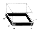
- FIG. 2 is a diagram showing an example of the appearance of the pallet P, and markers (reference objects) M including code information are pasted at positions such as four corners that are easily imaged from the motion sensing device 2.
- the marker M is associated with information for designating an image region (a three-dimensional image region including depth information) used to determine whether or not the worker H has entered the corresponding pallet P.
- An image area (pallet area) as indicated by a broken line with reference to the marker M is set.
- at least two markers M may be captured by the motion sensing device 2 with respect to each pallet P.
- An image area can also be set by the marker M.
- the pallet area is automatically set based on the marker M, it is not necessary to arrange the pallet P at a strict position, and even if the position is slightly shifted, the detection of the operation is not affected.
- FIG. 3 is a diagram illustrating a software configuration example of the information processing apparatus 1.
- the information processing apparatus 1 includes a motion sensing processing unit 11, a work management unit 12, an expert image superimposing display unit 13, and a work evaluation unit 14.
- the motion sensing processing unit 11 includes, in addition to the captured image, a data stream of the captured image (color moving image) and the depth image (the distance information from the viewpoint associated with each pixel of the captured image) of the motion sensing device 2. It has a function of generating skeleton information (skeleton information, joint information) including the position of a human body part (such as a joint) by calculation.
- Skeletal information includes "head”, “shoulder center” “left shoulder” “right shoulder” “left elbow” “left wrist” “left palm” “right elbow” “right wrist” “right palm” “center of spine” Position information such as the center of the waist, the base of the left foot, the base of the right foot, the left knee, the left ankle, the right knee, the right ankle, the left toe, and the right toe can be obtained in real time. Note that when the function of the motion sensing processing unit 11 is included in the motion sensing device 2, it is not necessary to provide the motion sensing processing unit 11 in the information processing device 1.
- the work management unit 12 has a function of managing the work performed by the worker H based on the captured image and the skeleton information output from the motion sensing processing unit 11. Details of the processing contents will be described later.
- the expert image superimposing display unit 13 superimposes and displays the expert's image on the work performed by the worker H based on the captured image and the skeleton information output from the motion sensing processing unit 11, so that the skill of the skilled worker is displayed on the worker H. Has a function to promote learning. Details of the processing contents will be described later.
- the work evaluation unit 14 has a function of numerically evaluating the work of the worker H based on the captured image and the skeleton information output from the motion sensing processing unit 11. Details of the processing contents will be described later.
- Information used for processing by the work management unit 12 or the like includes work information D1, pallet information D2, marker information D3, worker information D4, delay log information D5, error log information D6, skilled worker work information D7, and error range information D8. , Deviation information D9, model locus information D10, allowable range information D11, and evaluation information D12 are held.
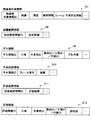
- the work information D1 includes “product ID / product name”, “process ID / process name”, “work ID”, “work title”, “instruction screen”, “work instruction text”, “corresponding pallet ID”, “hand to pallet”. “In / out”, “Right / left / both hands”, “Maximum start time / minimum time”, “Standard time / allowable time”, and the like.
- Product ID / Product name is information for identifying a product to be assembled.
- the “process ID / process name” is information for identifying a process in which product assembly or the like is divided into several stages.
- Work ID is information for identifying a work (procedure) obtained by subdividing a process. The work includes picking up an object, placing an object, assembling an object, and the like.
- “Work title” is a title indicating an outline of the work.
- the “instruction image” is an image showing details of work.
- the “work instruction text” is a character string indicating details of the work.
- the “corresponding pallet ID” is information indicating a pallet used for the work. When the process is combined, the pallet required in the process is specified.
- “Hand entering / exiting the pallet” is information indicating whether or not the operator's hand entering / exiting the pallet is used to determine the operation.
- “Separate right hand / left hand / both hands” is information indicating a worker's hand (right hand / left hand / both hands) designated to be entered / exited in the work.
- the position of the pallet on the work table is associated with the hand that the worker enters and exits, and is a position at which the work can proceed optimally.
- This position information can be used as a reference for placement by displaying on the screen when placing the pallet on the workbench before assembly of the product is started.
- Start maximum time / minimum time is information indicating the maximum time and minimum time allowed from the start of the work to the hand when the work involves entering / exiting the pallet.
- Standard time / allowable time is the standard time and allowable time until the work is completed when the work involves entering and exiting the pallet (allowable time for long and allowable time for short) ). Note that a series of work by the worker H is performed in units of processes, and work information regarding one process can be referred to as a “work scenario”.
- the pallet information D2 has items such as “pallet ID” and “corresponding marker ID”. “Pallet ID” is information for identifying a pallet. The “corresponding marker ID” is information for identifying a marker attached to the palette.
- the marker information D3 has items such as “marker ID” and “pallet area designation”. “Marker ID” is information for identifying a marker. “Palette area designation” is information for designating an image area for detecting the entry / exit of a hand with reference to a marker.
- the worker information D4 has items such as “worker ID” and “attribute”. “Worker ID” is information for identifying a worker. “Attribute” is information such as the name and affiliation of the worker.
- the delay log information D5 includes items such as “log ID”, “date and time”, “worker ID”, “product ID / process ID / work ID”, and “delay content”.
- Log ID is information for identifying delay log information.
- Date / time is information indicating the occurrence date / time of an event recorded as delay log information.
- the “worker ID” is information for identifying a worker who has performed work that is the target of the delay log information.
- “Product ID / Process ID / Work ID” is information for identifying the product / process / work of the work that is the target of the delay log information.
- the “delay content” is information indicating the content of the delay (such as the delay in the time when the hand has been put into the pallet and the delay time).
- the error log information D6 has items such as “log ID”, “date and time”, “worker ID”, “product ID / process ID / work ID”, and “error content”.
- Log ID is information for identifying error log information.
- Date and time is information indicating the date and time of occurrence of an event recorded as error log information.
- the “worker ID” is information for identifying a worker who has performed a work that is a target of error log information.
- “Product ID / Process ID / Work ID” is information for identifying the product / process / work of the work that is the target of the error log information.
- Error contents is information indicating the contents of an error (such as putting a hand different from the designated hand in the palette).
- the expert work information D7 includes items such as “expert work information ID”, “video”, “depth”, “skeleton information”, and “frame / work correspondence information”.
- the “skilled worker work information ID” is information for identifying skilled worker work information.
- Video is information of a captured image of work of an expert.
- Depth is information on the depth image of the work of an expert.
- Skleton information is skeleton information of the work of an expert.
- the “frame / work correspondence information” is information for associating a frame of a captured image of work of an expert with a target product / process / work.
- the error range information D8 has items such as “error range information ID” and “error range”. “Error range information ID” is information for identifying error range information. “Error range” is information indicating an error range (for example, a radius centered on a reference point).
- the deviation information D9 includes items such as “deviation information ID”, “date and time”, “worker ID”, “product ID / process ID / work ID”, and “deviation content”.
- the “deviation information ID” is information for identifying deviation information.
- “Date and time” is information indicating the date and time of occurrence of an event recorded as deviation information.
- the “worker ID” is information for identifying a worker who has performed a work that is a target of deviation information.
- “Product ID / Process ID / Work ID” is information for identifying the product / process / work of the work that is the target of the deviation information.
- the “deviation content” is information indicating the content of the deviation.
- the model locus information D10 has items such as “example information ID”, “frame number”, and “coordinate”.
- the “example information ID” is information for identifying example trajectory information as a reference for evaluation.
- the model trajectory information is in principle hand trajectory information, but if there is another body part whose motion is to be evaluated, the trajectory information about the part may be added.
- “Frame number” is information indicating the frame number of an image (moving image) in which a locus is recorded.
- Coordinats is information indicating the coordinates of the locus (two-dimensional coordinates and depth on the screen).
- the allowable range information D11 includes items such as “allowable range information ID” and “allowable range”. “Allowable range information ID” is information for identifying allowable range information. “Allowable range” is information indicating an allowable range (for example, a radius centered on a reference point).
- the evaluation information D12 includes items such as “evaluation information ID”, “date and time”, “worker ID”, “product ID / process ID / work ID”, and “evaluation value”.
- “Evaluation information ID” is information for identifying evaluation information.
- “Date and time” is information indicating the date and time of evaluation.
- “Worker ID” is information for identifying a worker who has performed a work recorded as evaluation information.
- “Product ID / Process ID / Work ID” is information for identifying the product / process / work of the work to be evaluated.
- evaluation value is information indicating the contents of evaluation.
- FIG. 6 is a diagram illustrating a hardware configuration example of the information processing apparatus 1.
- the information processing apparatus 1 includes a CPU (Central Processing Unit) 102, a ROM (Read Only Memory) 103, a RAM (Random Access Memory) 104, and an NVRAM (Non-Volatile Random Access Memory) connected to a system bus 101. 105.
- the information processing apparatus 1 includes an I / F (Interface) 106, an I / O (Input / Output Device) 107, an HDD (Hard Disk Drive) / flash memory 108, a NIC (Network) connected to the I / F 106.
- I / F Interface
- I / O Input / Output Device
- HDD Hard Disk Drive
- flash memory 108 Flash memory
- NIC Network
- a monitor 110 connected to the I / O 107, a keyboard 111, a mouse 112, and the like.
- a CD / DVD (Compact Disk / Digital Versatile Disk) drive or the like can also be connected to the I / O 107.
- the monitor 110 is not necessary.
- the functions of the information processing apparatus 1 described with reference to FIG. 3 are realized by the CPU 102 executing a predetermined program.
- the program may be acquired via a recording medium or may be acquired via a network.
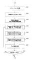
- FIG. 7 is a flowchart illustrating an example of work management processing performed by the work management unit 12 of the information processing apparatus 1.
- the work management unit 12 acquires a situation (product ID, process ID, pallet ID, worker ID) set in advance by an administrator or the like (step S101).
- the situation is set based on the work scenario (work information D1) by the administrator or the worker via the user interface screen provided by the information processing apparatus 1 for each work table.
- a product to be assembled product ID
- process ID an assembly process
- worker work ID
- the set situation data is held in a storage area in the information processing apparatus 1.
- the work management unit 12 waits for a work start trigger (step S102).
- the manager sends a start signal based on time, etc.
- the worker H operates the information processing apparatus 1 to send a start signal, or the worker H stands in front of the work table. Suppose that it is detected that the vehicle has stopped for a predetermined time.
- the work management unit 12 starts substantial processing (step S103).
- the work management unit 12 acquires the next work ID from the work information D1 and displays the screen (step S104).
- the process shifts to the next work after a predetermined time considering the standard time of work. Even in the case where the worker H does not enter or leave the pallet P, the work content is monitored by image processing or the like, and when it is determined that the work is completed, the process proceeds to the next work. Also good.
- FIG. 8 is a diagram showing an example of the display screen.
- the product number and the process number are displayed in the display area A1, the work title is displayed in the display area A2, and the work included in the current process is displayed in the display area A3.
- the title is displayed as a list, and the current work is highlighted as indicated by C1.
- An instruction image is displayed in the display area A4, and a work instruction text is displayed in the display area A5.
- the display area A6 is an area where error information is displayed, but no error information is displayed in the illustrated example.
- B1 and B2 are buttons for moving the work forward and backward.
- the work management unit 12 starts measurement from the initial value 0 for the first elapsed time (step S105).
- the first elapsed time is for determining the time to start moving from the instruction to start work on the screen until the worker H starts some operation.
- the work management unit 12 determines whether or not the worker H has entered the pallet associated with the work in the work scenario (work information D1) (step S106).
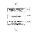
- FIG. 9 is a flowchart showing an example of a process for determining entry and exit of the hand from the pallet P, which is a process executed in parallel with each operation.
- the work management unit 12 detects a marker M corresponding to the current work ID from the captured image (step S121), and specifies a pallet area (step S122).
- the palette area is as shown by the broken line in FIG.
- the work management unit 12 compares the three-dimensional position (two-dimensional coordinates and depth of the captured image) of the skeletal information of the hand (right hand / left hand) with the three-dimensional position of the pallet area.
- a detection status (detection ⁇ non-detection, non-detection ⁇ detection) of whether the hand has entered or not is determined (step S123).
- Step S107 the work management unit 12 determines whether the first elapsed time has passed a predetermined value. If it is determined that the time has not elapsed (NO in step S107), the process returns to the determination of whether or not the hand has entered the pallet P (step S106). It should be noted that hand entry / exit detection is performed for all pallets on the workbench, and when a hand enters a pallet that is not associated with the current work, the screen display and recording are performed as an error. Good.
- the work management unit 12 determines whether or not the hand matches the hand associated with the work. (Step S108). When it is determined that the hand of the worker H has entered the predetermined pallet (YES in step S106), even when the first elapsed time is shorter than the minimum time, an alert display and recording that the work is started too early May be performed.
- the work management unit 12 determines that the hand matches the hand associated with the work (YES in step S108)
- the work management unit 12 starts measurement of the second elapsed time from an initial value: 0 (step S109).
- the second elapsed time is for determining whether or not the time for putting the hand in the pallet P is appropriate.
- the work management unit 12 determines whether or not the hand of the worker H has come out of the pallet P (step S110). For this determination, the hand detection situation described with reference to FIG. 9 is used.
- step S111 when the work management unit 12 determines that the hand of the worker H has not come out of the pallet P (NO in step S110), the work management unit 12 determines whether or not the second elapsed time is within an allowable range (step S111). If it is determined that the value is within the allowable range (YES in step S111), the process returns to the determination (step S110) as to whether or not the hand of the worker H has come out of the pallet P.
- step S110 When the work management unit 12 determines that the hand of the worker H has come out of the pallet P (YES in step S110), the work management unit 12 stops counting the second elapsed time (step S112), and displays the screen for the next work (step S112). Return to S104).
- step S112 When it is determined that the hand of the worker H has come out of the pallet P (YES in step S110), the work is too early even when the second elapsed time is shorter than the allowable time with respect to the standard time of the work.
- the alert display and recording may be performed.
- step S107 when the work management unit 12 determines that the first elapsed time has passed the predetermined value when the worker H's hand is not in the predetermined pallet (NO in step S106), (YES in step S107). It is determined that the worker H is at a loss. In this case, the work management unit 12 records the delay log information D5 as a delay, displays the delay information on the screen (step S113), resets the first elapsed time (step S114), and whether the pallet P has entered the hand. It returns to judgment (step S106) of no.
- FIG. 10 is a diagram showing an example of the display screen, and shows a state in which an alert “Error: This operation is not performed” is displayed in the display area A6.
- step S ⁇ b> 106 when the work management unit 12 determines that the hand of the worker H has entered the predetermined pallet (YES in step S ⁇ b> 106), the work management unit 12 determines that the hand does not match the hand associated with the work. If so (NO in step S108), it is determined that a work error (work error) has occurred. In this case, the work management unit 12 records the error log information D6 as an error (step S115), displays the error information on the screen (step S116), resets the first elapsed time (step S117), and stores it in the palette P. The process returns to the determination of whether or not a hand has entered (step S106).
- FIG. 11 is a diagram showing an example of the display screen, and shows a state in which an alert “Error: using right hand” is displayed in the display area A6.
- the work management unit 12 determines that the second elapsed time is not within the allowable range when it is determined that the hand of the worker H is not out of the pallet P (NO in step S110) (
- the delay log information D5 is recorded as a delay (step S111), the delay information is displayed on the screen (step S119), and the process proceeds to the reset of the first elapsed time (step S117).
- FIG. 12 is a flowchart illustrating a processing example of expert image superimposition display by the expert image superimposition display unit 13 of the information processing apparatus 1.
- the expert image superimposed display process may be performed independently or in parallel with the work management process illustrated in FIG.
- the expert image overlay display unit 13 acquires a situation (step S21), detects a work start trigger, and starts substantial processing (step S22). This corresponds to steps S101 to S103 in FIG. 7. However, when there are a plurality of expert work information and error range information to be superimposed, information for specifying what to use for processing (experts) Work information ID, error range information ID) are added to the situation.
- the process starts from step S23 after step S103 of FIG. In step S103 in FIG. 7, the first work of each process is started, and the next work is started when it is determined that the previous work has been completed by motion detection (such as a hand coming out of the pallet).
- the expert image superimposing display unit 13 acquires expert work information D7 and work error range information D8 (step S23).
- the expert image superimposed display unit 13 adjusts the trunk axis with respect to the expert work information D7 and the worker work information (captured image, skeleton information) (step S24).
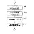
- FIG. 13 is a flowchart showing a processing example of adjustment of the trunk axis (step S24 in FIG. 12).
- the expert image superimposing display unit 13 acquires the trunk axis of the expert on the two-dimensional coordinates from the expert work information D7 (step S241).
- the expert image overlay display unit 13 acquires the operator's trunk axis on the two-dimensional coordinates (step S242).
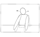
- FIG. 14 is a diagram showing an example of acquiring a trunk axis. For each of the worker H indicated by a solid line and the skilled person SH indicated by a broken line, the center of the head / shoulder, the center of the spine, and the waist The line that passes through the center of is acquired as the trunk axis.
- the expert image superimposing display unit 13 calculates the deviation of the trunk axes of the two (step S243), and rotates the image display of the expert so as to correct the deviation (step S244). .
- FIG. 15 is a diagram illustrating a screen example in which the image of the worker SH is superimposed on the image of the worker H.
- the image of the expert SH is set to have high transparency so as not to hinder the visual recognition of the image of the worker H. Since the trunk axis is adjusted so as to coincide with each other as much as possible, even if there is a difference in standing position or the like, a difference in a portion to be watched such as a hand movement is easily understood.
- the expert image overlay display unit 13 adjusts the timing with respect to the expert work information D7 and the worker work information (step S25).
- FIG. 16 is a flowchart showing a processing example of timing adjustment (step S25 in FIG. 12).
- the expert image overlay display unit 13 compares the current work IDs of the worker and the skilled worker (step S251), and determines whether or not the same work is being performed based on the work ID (step S252).
- the timing adjustment ends.
- the expert image superimposing display unit 13 determines whether the operation is advanced by the expert from the order of the operation ID (step S253).
- step S253 If it is determined that the expert is working (YES in step S253), the expert image superimposing display unit 13 pauses the reproduction of the expert work video and delays the timing (step S254). The process returns to ID acquisition (step S251).
- step S253 when it is determined that the expert is not working (the worker is working) (NO in step S253), the expert image superimposing display unit 13 displays the work image of the expert. (Step S255), the process returns to the acquisition of the work ID (step S251).
- the expert image overlay display unit 13 evaluates the degree of deviation of the expert work information D7 and the worker work information (step S26).
- FIG. 17 is a flowchart showing an example of processing for evaluating the deviation (step S26 in FIG. 12).
- the expert image superimposing display unit 13 acquires the joint positions of the expert and the worker (step S261).
- FIG. 18 is a diagram showing an example of application of the error range.
- a sphere whose radius is centered on the position a of the expert's joint is set as an error range, and it is determined whether or not the joint position of the operator is included therein. . Since the position b is inside the sphere, it is determined that it is within the error range, and since the position c is outside the sphere, it is determined that it exceeds the error range.
- the expert image superimposing display unit 13 marks the frame as a shifted frame (moving image frame) (step S264). Then, the expert image overlay display unit 13 highlights a range between the displaced joint and the adjacent joint (step S265).
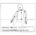
- FIG. 19 is a diagram showing an example of misalignment display or reporting. Since the positions of the right hand and the left hand are greatly deviated from the skilled person, the joint of the hand is highlighted (indicated by a bold line in the figure), and information about the misalignment is displayed. it's shown. In addition, you may display in real time and you may preserve
- the expert image overlay display unit 13 stores the information on the deviation (step S27), and when the work is not completed (NO in step S28), the trunk axis is adjusted (step S24). If the work is finished (YES in step S28), the process is finished. Note that when storing the information on the shift (step S27), the moving image superimposed and displayed during the shift period may be cut out and stored separately so that it can be played back later.
- the process may be performed based on the captured image and the skeleton information of the worker already recorded. Good.
- FIG. 20 is a flowchart illustrating an example of work evaluation processing performed by the work evaluation unit 14 of the information processing apparatus 1.
- the work evaluation process may be performed independently, or may be performed in parallel with the work management process illustrated in FIG. 7 and the expert image superimposed display process illustrated in FIG.
- step S31 when processing is performed independently, the work evaluation unit 14 acquires a situation (step S31), detects a work start trigger, and starts substantial processing (step S32).
- step S32 This corresponds to steps S101 to S103 in FIG. 7, but when there are a plurality of model trajectory information and allowable range information which are the criteria for evaluation, information for identifying the one to be used for processing (example trajectory). Information ID, allowable range information ID) is added to the situation.
- step S33 when performing in parallel with the process of FIG. 7, the process starts from step S33 after step S103 of FIG.
- step S103 in FIG. 7 the first work of each process is started, and the next work is started when it is determined that the previous work has been completed by motion detection (such as a hand coming out of the pallet).
- the work evaluation unit 14 acquires the model trajectory information D10 specified in the situation (step S33), and acquires the trajectory information of the worker (step S34).
- the model trajectory information is, in principle, hand trajectory information, and the trajectory of the worker to be compared with the hand trajectory information is also hand trajectory information.
- the trajectory information may be added. For example, for parts such as the head, shoulders, and back muscles, it is possible to evaluate whether or not the posture is appropriate from the deviation from the trace of the model.
- the work evaluation unit 14 determines the degree of coincidence between the trace information of the model and the trace information of the worker (Step S35).
- FIG. 21 is a flowchart showing a processing example of determination of the degree of coincidence of trajectories (step S35 in FIG. 20).
- the work evaluation unit 14 compares the model trajectory information with the joint position of the worker (step S351).
- FIG. 22 is a diagram showing an example of application of the allowable range, in which a sphere having a radius around the position d in each frame of the model trajectory information is set, and the trajectory position of the worker is included therein. Determine whether or not.
- step S36 the work evaluation unit 14 determines the degree of coincidence between the trace information of the model and the trace information of the worker (step S35). Return.
- step S36 the work evaluation unit 14 calculates the degree of trajectory mismatch (step S37).
- FIG. 23 is a flowchart showing a processing example of the calculation of the degree of discrepancy (step S37 in FIG. 20).
- the work evaluation unit 14 determines the inconsistency as The number of unmatched frames / the number of frames of the entire work is calculated (step S371).
- the number of unmatched frames is the number of frames marked as unmatched frames.
- a tube-shaped area considering the allowable range is set in the model trajectory, and the operator's trajectory is included in the area.
- the evaluation may be performed without considering the time required for the movement depending on whether it is included. Further, the time axis of either the model trajectory or the worker trajectory may be enlarged or reduced, and evaluation may be performed in consideration of both positional coincidence and temporal coincidence.
- the work evaluation unit 14 stores the calculated degree of mismatch (step S38), and ends the process.
- the stored inconsistency is used as a report as operator evaluation information. Evaluation of posture is useful for guidance for performing work safely.
Landscapes
- Engineering & Computer Science (AREA)
- General Engineering & Computer Science (AREA)
- Manufacturing & Machinery (AREA)
- Quality & Reliability (AREA)
- Physics & Mathematics (AREA)
- General Physics & Mathematics (AREA)
- Automation & Control Theory (AREA)
- General Factory Administration (AREA)
Abstract
L'invention concerne un procédé de surveillance destiné à surveiller les conditions d'exécution d'opérations contenues dans un scénario opérationnel, afin d'effectuer de manière appropriée une évaluation des opérations réellement effectuées. Les opérations faisant l'objet d'une exécution en suivant dans ledit scénario opérationnel, sont spécifiées sur la base des opérations dont l'accomplissement de l'exécution a été détectée. Selon le décalage entre une première ligne de mouvement dans une zone correspondant à la main mémorisée en correspondance avec lesdites opérations faisant l'objet d'une exécution en suivant ainsi spécifiées, et une seconde ligne de mouvement dans une zone correspondant à la main détectée à partir d'une image de capture capturée à l'aide d'un dispositif de capture d'image, une valeur d'évaluation concernant lesdites opérations faisant l'objet d'une exécution en suivant, est calculée, et un ordinateur exécute un traitement tel que ladite valeur d'évaluation ainsi calculée est émise en sortie.
Priority Applications (1)
| Application Number | Priority Date | Filing Date | Title |
|---|---|---|---|
| PCT/JP2015/071174 WO2017017741A1 (fr) | 2015-07-24 | 2015-07-24 | Procédé de surveillance, dispositif de traitement d'information, et programme de surveillance |
Applications Claiming Priority (1)
| Application Number | Priority Date | Filing Date | Title |
|---|---|---|---|
| PCT/JP2015/071174 WO2017017741A1 (fr) | 2015-07-24 | 2015-07-24 | Procédé de surveillance, dispositif de traitement d'information, et programme de surveillance |
Publications (1)
| Publication Number | Publication Date |
|---|---|
| WO2017017741A1 true WO2017017741A1 (fr) | 2017-02-02 |
Family
ID=57884430
Family Applications (1)
| Application Number | Title | Priority Date | Filing Date |
|---|---|---|---|
| PCT/JP2015/071174 Ceased WO2017017741A1 (fr) | 2015-07-24 | 2015-07-24 | Procédé de surveillance, dispositif de traitement d'information, et programme de surveillance |
Country Status (1)
| Country | Link |
|---|---|
| WO (1) | WO2017017741A1 (fr) |
Cited By (1)
| Publication number | Priority date | Publication date | Assignee | Title |
|---|---|---|---|---|
| JP2024116250A (ja) * | 2021-12-02 | 2024-08-27 | パナソニックIpマネジメント株式会社 | 作業データ分析装置、作業管理システム、作業データ分析方法及びプログラム |
Citations (3)
| Publication number | Priority date | Publication date | Assignee | Title |
|---|---|---|---|---|
| JP2003167613A (ja) * | 2001-11-30 | 2003-06-13 | Sharp Corp | 作業管理システム、作業管理方法、及びその方法を実現するためのプログラムを記憶した記録媒体 |
| JP2007124526A (ja) * | 2005-10-31 | 2007-05-17 | Hitachi Ltd | 画像監視記録装置及び画像監視記録システム |
| WO2011077696A1 (fr) * | 2009-12-22 | 2011-06-30 | パナソニック株式会社 | Dispositif d'analyse d'action et procédé d'analyse d'action |
-
2015
- 2015-07-24 WO PCT/JP2015/071174 patent/WO2017017741A1/fr not_active Ceased
Patent Citations (3)
| Publication number | Priority date | Publication date | Assignee | Title |
|---|---|---|---|---|
| JP2003167613A (ja) * | 2001-11-30 | 2003-06-13 | Sharp Corp | 作業管理システム、作業管理方法、及びその方法を実現するためのプログラムを記憶した記録媒体 |
| JP2007124526A (ja) * | 2005-10-31 | 2007-05-17 | Hitachi Ltd | 画像監視記録装置及び画像監視記録システム |
| WO2011077696A1 (fr) * | 2009-12-22 | 2011-06-30 | パナソニック株式会社 | Dispositif d'analyse d'action et procédé d'analyse d'action |
Cited By (1)
| Publication number | Priority date | Publication date | Assignee | Title |
|---|---|---|---|---|
| JP2024116250A (ja) * | 2021-12-02 | 2024-08-27 | パナソニックIpマネジメント株式会社 | 作業データ分析装置、作業管理システム、作業データ分析方法及びプログラム |
Similar Documents
| Publication | Publication Date | Title |
|---|---|---|
| US11842511B2 (en) | Work analyzing system and work analyzing method | |
| JP7611093B2 (ja) | 作業支援システムおよび作業支援方法 | |
| US9761047B2 (en) | Virtual mask fitting system | |
| Valero et al. | Analysis of construction trade worker body motions using a wearable and wireless motion sensor network | |
| US8509490B2 (en) | Trajectory processing apparatus and method | |
| US11426099B2 (en) | Mobile device avatar generation for biofeedback to customize movement control | |
| JP6951685B2 (ja) | 動作分析システム、動作分析装置、動作分析方法及び動作分析プログラム | |
| WO2017017739A1 (fr) | Système de gestion opérationnelle, procédé de gestion opérationnelle, dispositif de traitement d'information, et programme de gestion opérationnelle | |
| JP7004218B2 (ja) | 動作分析装置、動作分析方法、動作分析プログラム及び動作分析システム | |
| CN114846514A (zh) | 作业分析装置和作业分析方法 | |
| JP6231302B2 (ja) | 検査補助装置 | |
| JP6676322B2 (ja) | 負担評価装置、負担評価方法 | |
| JP7125872B2 (ja) | 作業支援装置、および、作業支援方法 | |
| JP7114885B2 (ja) | 作業現場監視装置およびプログラム | |
| JP2019159885A (ja) | 動作分析装置、動作分析方法、動作分析プログラム及び動作分析システム | |
| US10860845B2 (en) | Method and system for automatic repetitive step and cycle detection for manual assembly line operations | |
| US20210192771A1 (en) | Calculation system, calculation method, and storage medium | |
| WO2021250931A1 (fr) | Système de détection de squelette et dispositif de gestion de travail | |
| WO2017017737A1 (fr) | Procédé d'affichage, procédé de sortie de résultat de surveillance, dispositif de traitement d'information, programme d'affichage | |
| WO2020136924A1 (fr) | Dispositif d'analyse de mouvement, procédé d'analyse de mouvement et programme d'analyse de mouvement | |
| JP7165108B2 (ja) | 作業訓練システム及び作業訓練支援方法 | |
| KR20200073588A (ko) | 작업자 동작인식을 이용한 생산라인 모니터링 시스템 및 이를 이용하여 생산라인을 모니터링하는 방법 | |
| WO2017017741A1 (fr) | Procédé de surveillance, dispositif de traitement d'information, et programme de surveillance | |
| JP6857052B2 (ja) | ロボット設定装置、ロボット設定方法、ロボット設定プログラム及びコンピュータで読み取り可能な記録媒体並びに記録した機器 | |
| JP7500895B1 (ja) | 作業管理装置、作業管理システム、および、作業管理方法 |
Legal Events
| Date | Code | Title | Description |
|---|---|---|---|
| 121 | Ep: the epo has been informed by wipo that ep was designated in this application |
Ref document number: 15899575 Country of ref document: EP Kind code of ref document: A1 |
|
| NENP | Non-entry into the national phase |
Ref country code: DE |
|
| 122 | Ep: pct application non-entry in european phase |
Ref document number: 15899575 Country of ref document: EP Kind code of ref document: A1 |
|
| NENP | Non-entry into the national phase |
Ref country code: JP |