WO2017017742A1 - 画像処理装置、画像処理方法およびプログラム - Google Patents
画像処理装置、画像処理方法およびプログラム Download PDFInfo
- Publication number
- WO2017017742A1 WO2017017742A1 PCT/JP2015/071175 JP2015071175W WO2017017742A1 WO 2017017742 A1 WO2017017742 A1 WO 2017017742A1 JP 2015071175 W JP2015071175 W JP 2015071175W WO 2017017742 A1 WO2017017742 A1 WO 2017017742A1
- Authority
- WO
- WIPO (PCT)
- Prior art keywords
- noise
- pixel
- unit
- image
- image data
- Prior art date
- Legal status (The legal status is an assumption and is not a legal conclusion. Google has not performed a legal analysis and makes no representation as to the accuracy of the status listed.)
- Ceased
Links
Images








Classifications
-
- H—ELECTRICITY
- H04—ELECTRIC COMMUNICATION TECHNIQUE
- H04N—PICTORIAL COMMUNICATION, e.g. TELEVISION
- H04N1/00—Scanning, transmission or reproduction of documents or the like, e.g. facsimile transmission; Details thereof
- H04N1/40—Picture signal circuits
- H04N1/409—Edge or detail enhancement; Noise or error suppression
-
- G—PHYSICS
- G06—COMPUTING OR CALCULATING; COUNTING
- G06T—IMAGE DATA PROCESSING OR GENERATION, IN GENERAL
- G06T5/00—Image enhancement or restoration
- G06T5/50—Image enhancement or restoration using two or more images, e.g. averaging or subtraction
-
- G—PHYSICS
- G06—COMPUTING OR CALCULATING; COUNTING
- G06T—IMAGE DATA PROCESSING OR GENERATION, IN GENERAL
- G06T5/00—Image enhancement or restoration
- G06T5/70—Denoising; Smoothing
-
- H—ELECTRICITY
- H04—ELECTRIC COMMUNICATION TECHNIQUE
- H04N—PICTORIAL COMMUNICATION, e.g. TELEVISION
- H04N23/00—Cameras or camera modules comprising electronic image sensors; Control thereof
- H04N23/60—Control of cameras or camera modules
- H04N23/66—Remote control of cameras or camera parts, e.g. by remote control devices
- H04N23/663—Remote control of cameras or camera parts, e.g. by remote control devices for controlling interchangeable camera parts based on electronic image sensor signals
-
- H—ELECTRICITY
- H04—ELECTRIC COMMUNICATION TECHNIQUE
- H04N—PICTORIAL COMMUNICATION, e.g. TELEVISION
- H04N23/00—Cameras or camera modules comprising electronic image sensors; Control thereof
- H04N23/80—Camera processing pipelines; Components thereof
- H04N23/81—Camera processing pipelines; Components thereof for suppressing or minimising disturbance in the image signal generation
-
- H—ELECTRICITY
- H04—ELECTRIC COMMUNICATION TECHNIQUE
- H04N—PICTORIAL COMMUNICATION, e.g. TELEVISION
- H04N23/00—Cameras or camera modules comprising electronic image sensors; Control thereof
- H04N23/80—Camera processing pipelines; Components thereof
- H04N23/84—Camera processing pipelines; Components thereof for processing colour signals
- H04N23/843—Demosaicing, e.g. interpolating colour pixel values
-
- H—ELECTRICITY
- H04—ELECTRIC COMMUNICATION TECHNIQUE
- H04N—PICTORIAL COMMUNICATION, e.g. TELEVISION
- H04N25/00—Circuitry of solid-state image sensors [SSIS]; Control thereof
- H04N25/60—Noise processing, e.g. detecting, correcting, reducing or removing noise
- H04N25/616—Noise processing, e.g. detecting, correcting, reducing or removing noise involving a correlated sampling function, e.g. correlated double sampling [CDS] or triple sampling
-
- H—ELECTRICITY
- H04—ELECTRIC COMMUNICATION TECHNIQUE
- H04N—PICTORIAL COMMUNICATION, e.g. TELEVISION
- H04N25/00—Circuitry of solid-state image sensors [SSIS]; Control thereof
- H04N25/60—Noise processing, e.g. detecting, correcting, reducing or removing noise
- H04N25/618—Noise processing, e.g. detecting, correcting, reducing or removing noise for random or high-frequency noise
-
- H—ELECTRICITY
- H04—ELECTRIC COMMUNICATION TECHNIQUE
- H04N—PICTORIAL COMMUNICATION, e.g. TELEVISION
- H04N25/00—Circuitry of solid-state image sensors [SSIS]; Control thereof
- H04N25/60—Noise processing, e.g. detecting, correcting, reducing or removing noise
- H04N25/68—Noise processing, e.g. detecting, correcting, reducing or removing noise applied to defects
-
- H—ELECTRICITY
- H04—ELECTRIC COMMUNICATION TECHNIQUE
- H04N—PICTORIAL COMMUNICATION, e.g. TELEVISION
- H04N25/00—Circuitry of solid-state image sensors [SSIS]; Control thereof
- H04N25/70—SSIS architectures; Circuits associated therewith
-
- H—ELECTRICITY
- H04—ELECTRIC COMMUNICATION TECHNIQUE
- H04N—PICTORIAL COMMUNICATION, e.g. TELEVISION
- H04N25/00—Circuitry of solid-state image sensors [SSIS]; Control thereof
- H04N25/70—SSIS architectures; Circuits associated therewith
- H04N25/76—Addressed sensors, e.g. MOS or CMOS sensors
- H04N25/78—Readout circuits for addressed sensors, e.g. output amplifiers or A/D converters
-
- H—ELECTRICITY
- H04—ELECTRIC COMMUNICATION TECHNIQUE
- H04N—PICTORIAL COMMUNICATION, e.g. TELEVISION
- H04N5/00—Details of television systems
- H04N5/14—Picture signal circuitry for video frequency region
- H04N5/21—Circuitry for suppressing or minimising disturbance, e.g. moiré or halo
-
- G—PHYSICS
- G06—COMPUTING OR CALCULATING; COUNTING
- G06T—IMAGE DATA PROCESSING OR GENERATION, IN GENERAL
- G06T2207/00—Indexing scheme for image analysis or image enhancement
- G06T2207/20—Special algorithmic details
- G06T2207/20212—Image combination
- G06T2207/20216—Image averaging
Definitions
- the present invention relates to an image processing apparatus, an image processing method, and a program for correcting blinking defect noise in which a pixel value such as RTS noise generated in an image sensor having a plurality of pixels arranged two-dimensionally varies within a certain range. .
- CMOS Complementary Metal Oxide Semiconductor
- CMOS Complementary Metal Oxide Semiconductor
- a shared pixel structure that reads a signal by sharing a plurality of pixels with one readout circuit reduces the area required for the circuit in the image sensor, and the aperture ratio ( The sensitivity is improved by improving the ratio of the light receiving part).
- the noise generated in the image sensor includes a defective pixel whose pixel value always shows an abnormal value, and a pixel value other than a dark current shot noise caused by a dark current and a random noise caused by a thermal noise in a readout circuit.
- RTS Random Telegraph Signal
- As a technique for correcting this RTS noise a pixel value of a target pixel in a captured image, a pixel value of a peripheral pixel of the target pixel, and a noise level of RTS noise detected in advance for each pixel of an image sensor (hereinafter referred to as “RTS noise”).
- RTS noise a technique for correcting this RTS noise, a pixel value of a target pixel in a captured image, a pixel value of a peripheral pixel of the target pixel, and a noise level of RTS noise detected in advance for each pixel of an image sensor (hereinafter referred to as “RTS noise”).
- Patent Document 1 when the correlation between the pixel value of the target pixel and the pixel values of the peripheral pixels of the target image is high, RTS noise can be reduced.
- the image quality may be deteriorated because the correlation between the pixel value of the pixel of interest and the pixel value of surrounding pixels is low.
- the present invention has been made in view of the above, and an image processing apparatus and image processing capable of improving image quality even when the pixel value of a pixel of interest and the pixel value of peripheral pixels are low
- An object is to provide a method and a program.
- an image processing apparatus is arranged in a two-dimensional manner, and receives a plurality of pixels that receive light from the outside and generate a signal according to the amount of received light.
- An image processing apparatus that corrects blinking defect noise included in image data generated by an image sensor having a plurality of readout circuits that read out the signals as pixel values, and the blinking defect noise caused by the readout circuit is generated
- An acquisition unit that acquires position information of the readout circuit or position information of each of the plurality of pixels and the image data, and the image data acquired by the acquisition unit is image data to be corrected
- the correction target image data based on the reference image data based on the image data acquired at a different time from the correction target image data and the noise information.
- a correcting unit for correcting the pixel value of kicking the target pixel characterized by comprising a.
- the image processing apparatus further includes a movement amount calculation unit that calculates a movement amount of a subject based on the correction target image data and the reference image data. Based on the movement amount calculated by the movement amount calculation unit, a reference pixel of the reference image data corresponding to the pixel of interest or a pixel near the pixel of interest is obtained, and based on a pixel value of the reference pixel, The pixel value of the target pixel is corrected.
- the image processing apparatus is the image processing apparatus according to the above invention, wherein the correction unit reduces noise in the target pixel when the flashing defect noise occurs in the target pixel as compared with a case where the flashing defect noise does not occur. It is characterized by increasing the strength of processing.
- the correction unit increases the strength of noise reduction processing in the time direction using the reference image data when the blinking defect noise occurs in the target pixel. It is characterized by doing.
- the image processing apparatus is the image processing apparatus according to the above invention, wherein, when the blinking defect noise occurs in the target pixel, the correction unit performs a spatial noise reduction process using pixels around the target pixel. It is characterized by increasing.
- the correction unit calculates a representative value corresponding to a pixel value when the blinking defect noise does not occur, based on a pixel value of the reference pixel, The pixel value of the target pixel is corrected based on the representative value.
- the correction unit calculates the representative value based on a pixel value of the pixel of interest.
- the correction unit is based on a pixel value of the reference pixel in which the blinking defect noise does not occur or a pixel value of the reference pixel in which the blinking defect noise is corrected.
- the representative value is calculated.
- the correction unit calculates the representative value based on pixel values of surrounding pixels in the target pixel in which the blinking defect noise does not occur.
- the image processing apparatus further includes a noise amount estimation unit that estimates a random noise amount around the target pixel in the above invention, and the correction unit is configured to perform the above-described correction based on the random noise amount. A representative value is calculated.
- the noise information corresponds to position information of the reading circuit or position information of each of the plurality of pixels in which blinking defect noise caused by the reading circuit is generated. And further includes a blinking defect noise level that is a noise level of the blinking defect noise, and the correction unit corrects the pixel value of the pixel of interest using the blinking defect noise level.
- the noise information corresponds to position information of the reading circuit or position information of each of the plurality of pixels in which blinking defect noise caused by the reading circuit is generated. And further includes a blinking defect noise level that is a noise level of the blinking defect noise, and the correction unit increases the intensity of noise reduction processing in the target pixel as the blinking defect noise level increases.
- the noise information corresponds to position information of the reading circuit or position information of each of the plurality of pixels in which blinking defect noise caused by the reading circuit is generated.
- a blinking defect noise level that is a noise level of the blinking defect noise is further included, and the correction unit calculates the representative value based on the blinking defect noise level.
- the image processing apparatus further includes a reliability calculation unit that calculates a reliability indicating the certainty of the movement amount calculated by the movement amount calculation unit in the above invention, and the correction unit includes the reliability The representative value is calculated based on the degree.
- the reference image data is the image data generated by the image sensor immediately before the image data corresponding to the correction target image data. To do.
- the reference image data is image data corrected by the correction unit immediately before the correction unit corrects the correction target image data. It is characterized by.
- the reference image data is a plurality of the image data generated by the imaging element before the image data corresponding to the correction target image data. It is characterized by.
- the blinking defect noise is random telegraph signal noise.
- the image processing method is arranged in a two-dimensional manner, receives a light from the outside, generates a signal corresponding to the amount of received light, and a plurality of readout circuits that read the signal as a pixel value And an image processing method executed by an image processing apparatus that corrects blinking defect noise included in image data generated by an image pickup device having a position of the readout circuit where the blinking defect noise caused by the readout circuit is generated Information or noise information including position information of each of the plurality of pixels and the image data, and the correction target image data using the image data acquired in the acquisition step as the correction target image data.
- the correction target image data based on the reference image data based on the image data acquired at a different time and the noise information Characterized in that it comprises a correction step of correcting the pixel value of the definitive target pixel.
- a program according to the present invention is arranged in a two-dimensional manner, receives a light from the outside, generates a signal according to the amount of received light, a plurality of readout circuits that read the signal as a pixel value,
- the image processing apparatus that corrects the blinking defect noise included in the image data generated by the image pickup device having the position information of the readout circuit or the position of each of the plurality of pixels in which the blinking defect noise due to the readout circuit is generated
- a correction step that, characterized in that for the execution.
- the image quality can be improved even when the pixel value of the target pixel and the pixel values of the surrounding pixels are low in correlation.
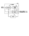
- FIG. 1 is a block diagram schematically showing a configuration of an imaging system according to Embodiment 1 of the present invention.
- FIG. 2 is a schematic diagram schematically showing the configuration of the main part of the image sensor included in the imaging apparatus according to Embodiment 1 of the present invention.
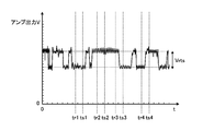
- FIG. 3 is a diagram illustrating an example of fluctuations in the amplifier output output from the amplifier unit when RTS noise is generated in the case where the image sensor according to Embodiment 1 of the present invention is shielded from light so that light does not strike. It is.
- FIG. 4 is a diagram illustrating an example of a distribution of pixel values read using the amplifier unit that generates RTS noise according to the first embodiment of the present invention.
- FIG. 1 is a block diagram schematically showing a configuration of an imaging system according to Embodiment 1 of the present invention.
- FIG. 2 is a schematic diagram schematically showing the configuration of the main part of the image sensor included in the imaging apparatus according to Embodiment 1 of the present invention.
- FIG. 3 is
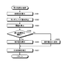
- FIG. 5 is a flowchart showing an outline of processing executed by the image processing apparatus according to Embodiment 1 of the present invention.
- FIG. 6 is a diagram illustrating an example of a noise model stored in a lookup table provided in the image processing apparatus according to Embodiment 1 of the present invention.
- FIG. 7 is a flowchart showing an overview of the time direction NR process of FIG.
- FIG. 8 is a diagram showing a relationship between RTS_Value and coefficient Co_we_pre set by the noise reduction processing unit included in the image processing apparatus according to Embodiment 1 of the present invention.
- FIG. 9 is a flowchart showing an outline of the spatial direction NR process of FIG. FIG.
- FIG. 10 is a diagram showing a relationship between RTS_Value and coefficient Co_Cb set by the noise reduction processing unit included in the image processing apparatus according to Embodiment 1 of the present invention.
- FIG. 11 is a block diagram schematically showing the configuration of the imaging system according to Embodiment 2 of the present invention.
- FIG. 12 is a block diagram showing a detailed configuration of the RTS noise correction unit according to Embodiment 2 of the present invention.
- FIG. 13 is a block diagram showing a detailed configuration of the representative value calculation unit according to Embodiment 2 of the present invention.
- FIG. 14 is a block diagram showing a detailed configuration of a correction value calculation unit according to Embodiment 2 of the present invention.
- FIG. 11 is a block diagram schematically showing the configuration of the imaging system according to Embodiment 2 of the present invention.
- FIG. 12 is a block diagram showing a detailed configuration of the RTS noise correction unit according to Embodiment 2 of the present invention.
- FIG. 13 is a
- FIG. 15 is a flowchart showing an outline of processing executed by the image processing apparatus according to Embodiment 2 of the present invention.
- FIG. 16 is a flowchart showing an overview of the representative value calculation processing of FIG.
- FIG. 17 is a flowchart showing an outline of the correction value calculation processing of FIG.
- FIG. 18 is a block diagram showing a detailed configuration of the noise reduction unit according to Embodiment 3 of the present invention.
- FIG. 19 is a block diagram showing a detailed configuration of the RTS noise correction unit according to Embodiment 3 of the present invention.
- FIG. 20 is a flowchart showing an outline of representative value calculation processing executed by the image processing apparatus according to Embodiment 3 of the present invention.
- FIG. 21 is a block diagram showing a detailed configuration of an RTS noise correction unit according to a modification of the third embodiment of the present invention.
- FIG. 22 is a flowchart showing an overview of representative value calculation processing according to a modification of the third embodiment of the present invention.
- FIG. 23 is a diagram schematically illustrating a blend rate calculation method calculated by the representative value determination unit according to the modification of the third embodiment of the present invention.
- FIG. 24 is a block diagram showing a detailed configuration of the noise reduction unit according to Embodiment 4 of the present invention.
- FIG. 25 is a block diagram showing a detailed configuration of the RTS noise correction unit according to Embodiment 4 of the present invention.
- FIG. 22 is a flowchart showing an overview of representative value calculation processing according to a modification of the third embodiment of the present invention.
- FIG. 23 is a diagram schematically illustrating a blend rate calculation method calculated by the representative value determination unit according to the modification of the third embodiment of the present invention.
- FIG. 24 is a block diagram
- FIG. 26 is a flowchart showing an outline of representative value calculation processing executed by the image processing apparatus according to Embodiment 4 of the present invention.
- FIG. 27 is a block diagram showing a detailed configuration of the RTS noise correction unit according to the first modification of the fourth embodiment of the present invention.
- FIG. 28 is a flowchart showing an outline of representative value calculation processing executed by the image processing apparatus according to the first modification of the fourth embodiment of the present invention.
- FIG. 29 is a flowchart showing an outline of representative value calculation processing executed by the image processing apparatus according to the second modification of the fourth embodiment of the present invention.
- FIG. 30 is a flowchart showing an outline of representative value calculation processing executed by the image processing apparatus according to the third modification of the fourth embodiment of the present invention.
- FIG. 31 is a block diagram schematically showing the configuration of the imaging system according to Embodiment 5 of the present invention.
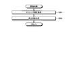
- FIG. 32 is a flowchart showing an outline of processing executed by the imaging system according to Embodiment 5 of the present invention.
- FIG. 33 is a flowchart showing an outline of the image processing of FIG.
- FIG. 1 is a block diagram schematically showing a configuration of an imaging system according to Embodiment 1 of the present invention.
- the imaging system 1 illustrated in FIG. 1 includes an imaging device 10, an image processing device 30, and a display device 40.
- the imaging apparatus 10 includes an optical system 101, a diaphragm 102, a shutter 103, a driver 104, an imaging element 105, an analog processing unit 106, an A / D conversion unit 107, and an operation unit. 108, a memory I / F unit 109, a recording medium 110, a volatile memory 111, a nonvolatile memory 112, a bus 113, an imaging control unit 114, and a first external I / F unit 115.
- the optical system 101 is configured using one or a plurality of lenses.
- the optical system 101 is configured using, for example, a focus lens and a zoom lens.
- the diaphragm 102 adjusts exposure by limiting the amount of incident light collected by the optical system 101.
- the diaphragm 102 limits the amount of incident light collected by the optical system 101 under the control of an imaging control unit 114 described later. Note that the amount of incident light may be limited using an electronic shutter in the shutter 103 or the image sensor 105 without using the diaphragm 102. Note that the optical system 101 and the diaphragm 102 may be detachable from the imaging apparatus 10.
- the shutter 103 sets the state of the image sensor 105 to an exposure state or a light shielding state.
- the shutter 103 is configured using, for example, a focal plane shutter. Note that an electronic shutter in the image sensor 105 may be used without using the shutter 103.
- the driver 104 drives the optical system 101, the diaphragm 102, and the shutter 103 under the control of an imaging control unit 114 described later.
- the driver 104 moves the optical system 101 along the optical axis O1 to change the zoom magnification of the imaging apparatus 10 or adjust the focus position.
- the imaging element 105 receives light collected by the optical system 101 under the control of an imaging control unit 114 described later, converts the light into image data (electric signal), and outputs the image data.
- the image sensor 105 is configured using a CMOS (Complementary Metal Oxide Semiconductor) or the like in which a plurality of pixels are two-dimensionally arranged.
- a Bayer array RGB filter is arranged in front of each pixel. Note that the image sensor 105 is not limited to the Bayer array, and may of course be a stacked type such as Fovion.
- the filter to be used is not limited to RGB, and any filter such as a complementary color filter can be applied.
- a light source capable of irradiating different color lights in a time-sharing manner is arranged, and no color filter is arranged in the image sensor 105, and a color image is configured using images that are sequentially captured while changing the irradiating color. You may be able to do it.
- the image sensor 105 has an electronic shutter function that can electronically control the amount of received light.
- FIG. 2 is a schematic diagram schematically showing the configuration of the main part of the image sensor 105.
- 2 shows an example in which a readout circuit is shared by a plurality of pixels in order to improve sensitivity by improving the aperture ratio of the pixels.
- 2 includes one readout circuit for 8 pixels of 2 pixels in the horizontal direction (horizontal direction) ⁇ 4 pixels in the vertical direction (vertical direction).
- FIG. 2 an example in which one readout circuit is grouped with respect to 8 pixels of 2 pixels in the horizontal direction (horizontal direction) ⁇ 4 pixels in the vertical direction (vertical direction) has been described. It is assumed that the above-described pixels and readout circuits are arranged side by side in the horizontal direction and the vertical direction on the image sensor 105 of the first embodiment.
- the image sensor 105 receives light by exposure and performs photoelectric conversion to generate a plurality of pixels 105a (photodiodes) that generate charges corresponding to the exposure amount, and a plurality of pixels 105a.
- a first switch 105b that is provided in each and opens and closes according to the control of the imaging control unit 114, a vertical transfer line 105c that transfers a signal (charge) output from each of the plurality of pixels 105a in the vertical direction, and a plurality of An FD unit 105d (Floating Diffusion) that accumulates signals output from each of the pixels 105a, an amplifier unit 105e that amplifies signals output from the FD unit 105d, and a second that opens and closes according to the control of the imaging control unit 114
- a switch 105f, a control line 105g for controlling the second switch 105f, and a transfer line 10 for transferring the electric signal amplified by the amplifier unit 105e. Includes a h, the.
- the image sensor 105 configured as described above reads out a signal corresponding to the exposure amount in the pixels 105a (1) to 105a (8) as a pixel value
- the FD unit 105d is set in a reset state, and the imaging control unit 114 is reset.
- the imaging control unit 114 turns on the second switch 105f, the imaging element 105 amplifies the charge accumulated in the FD unit 105d by the amplifier unit 105e and reads (outputs) the pixel value.
- the imaging element 105 resets the FD unit 105d, and the imaging control unit 114 turns on only the first switch 105b (2), whereby the charge generated in the pixel 105a (2) is transferred to the FD unit 105d. Forward to. Thereafter, when the imaging control unit 114 turns on the second switch 105f, the imaging element 105 amplifies the charge accumulated in the FD unit 105d by the amplifier unit 105e and reads it as a pixel value.
- the imaging element 105 can sequentially output signals corresponding to the exposure amounts in the pixels 105a (1) to 105a (8) as pixel values by sequentially performing such readout operations.
- the amplifier unit 105e functions as a readout circuit that reads out charges from each of the plurality of pixels 105a.
- the analog processing unit 106 performs predetermined analog processing on the analog signal input from the image sensor 105 and outputs the analog signal to the A / D conversion unit 107. Specifically, the analog processing unit 106 performs noise reduction processing, gain increase processing, and the like on the analog signal input from the image sensor 105. For example, the analog processing unit 106 performs waveform shaping on the analog signal after reducing reset noise and the like, and further increases the gain so that the target brightness is obtained.
- the A / D conversion unit 107 generates digital image data (hereinafter referred to as “RAW image data”) by performing A / D conversion on the analog signal input from the analog processing unit 106, and the bus 113. Is output to the volatile memory 111.
- RAW image data digital image data
- the A / D conversion unit 107 may directly output RAW image data to each unit of the imaging apparatus 10 to be described later.
- the above-described analog processing unit 106 and A / D conversion unit 107 may be provided in the image sensor 105 so that the image sensor 105 directly outputs digital RAW image data.
- the operation unit 108 gives various instructions of the imaging apparatus 10.
- the operation unit 108 includes a power switch that switches the power state of the imaging device 10 to an on state or an off state, a release switch that gives a still image shooting instruction, an operation switch that switches various settings of the imaging device 10, and a moving image shooting. And a moving image switch for giving instructions.
- the recording medium 110 is configured using a memory card that is mounted from the outside of the imaging device 10, and is detachably mounted on the imaging device 10 via the memory I / F unit 109. Further, the recording medium 110 may output a program and various types of information to the nonvolatile memory 112 via the memory I / F unit 109 under the control of an imaging control unit 114 described later.
- the volatile memory 111 temporarily stores image data input from the A / D conversion unit 107 via the bus 113.
- the volatile memory 111 temporarily stores image data that the image sensor 105 sequentially outputs for each frame via the analog processing unit 106, the A / D conversion unit 107, and the bus 113.
- the volatile memory 111 is configured using SDRAM (Synchronous Dynamic Random Access Memory) or the like.
- the nonvolatile memory 112 is configured using a flash memory or the like, and records various programs for operating the imaging apparatus 10 and various data used during execution of the programs.
- the nonvolatile memory 112 includes RTS noise caused by the program recording unit 112a and the position information of the readout circuit (amplifier unit 105e) that reads out the pixel value or the position information of each of the plurality of pixels 105a and the readout circuit (amplifier unit 105e).
- An RTS noise information recording unit 112b that records RTS noise position information associated with feature quantities related to the random noise model, and a random noise model information recording unit 112c that records one or more random noise models.
- the feature amount is one of the amplitude of RTS noise (RTS_Value), the occurrence frequency of blinking defect noise, and the occurrence frequency of RTS noise less than the amplitude of RTS noise.
- the bus 113 is configured by using a transmission path or the like that connects each component of the imaging device 10, and transfers various data generated inside the imaging device 10 to each component of the imaging device 10.
- the imaging control unit 114 is configured by using a CPU (Central Processing Unit) or the like, and performs an instruction, data transfer, or the like to each unit constituting the imaging apparatus 10 in accordance with an instruction signal or a release signal from the operation unit 108.
- the operation of the apparatus 10 is comprehensively controlled.
- the imaging control unit 114 starts controlling the shooting operation in the imaging device 10.
- the photographing operation in the image pickup apparatus 10 means that the analog processing unit 106 and the A / D conversion unit 107 are predetermined with respect to the exposure timing of the image pickup element 105, the output timing of the analog signal, and the analog signal output from the image pickup element 105. This is the operation to perform the process.
- the image data thus processed is recorded on the recording medium 110 via the bus 113 and the memory I / F unit 109 under the control of the imaging control unit 114.
- the first external I / F unit 115 outputs information input from an external device via the bus 113 to the nonvolatile memory 112 or the volatile memory 111, while the volatile memory 111 stores the information to an external device via the bus 113.
- Information, information stored in the nonvolatile memory 112, and image data generated by the image sensor 105 are output.
- the first external I / F unit 115 outputs RAW image data, RTS noise information, and random noise model information generated by the image sensor 105 to the image processing apparatus 30 via the bus 113.
- the image processing device 30 includes a third external I / F unit 31, an interpolation processing unit 32, a frame memory 33, a motion detection unit 34, a noise reduction unit 35, a storage unit 36, an operation unit 37, an image A processing unit 38 and an image processing control unit 39 are provided.
- the third external I / F unit 31 records the image data generated by the image sensor 105 via the first external I / F unit 115 of the imaging apparatus 10 and the RTS recorded by the RTS noise information recording unit 112b in the nonvolatile memory 112.
- RTS noise information related to noise and random noise model information recorded by the random noise model information recording unit 112c are acquired, and the acquired raw image data (correction target image data), RTS noise information, and random noise model information are interpolated by the interpolation processing unit 32 and The data is output to the storage unit 36.
- the third external I / F unit 31 and the first external I / F unit 115 are connected via, for example, a control cable capable of exchanging information bidirectionally or wireless communication.
- the third external I / F unit 31 functions as an acquisition unit.
- the interpolation processing unit 32 performs an interpolation process on the RAW image data generated by the image sensor 105 input from the third external I / F unit 31. Specifically, when the image sensor 105 is a Bayer array, the interpolation processing unit 32 performs an interpolation process on each pixel of a RAW image (hereinafter, “current image”) corresponding to the RAW image data. The missing pixel value (signal value) is interpolated to generate a current image having all the pixel values of the R, G, and B signals in each pixel, and this current image is output to the noise reduction unit 35.
- current image a RAW image
- the frame memory 33 is bi-directionally connected to the noise reduction unit 35 and temporarily stores frame data of an image to be displayed on the display device 40.
- the motion detection unit 34 stores the current image input from the interpolation processing unit 32 and the frame memory 33, the current image whose noise is corrected by the noise reduction unit 35, and the corrected image that is temporally continuous with the current image. Based on the corrected image corresponding to the data (hereinafter referred to as “past image”), the motion vector (movement amount) of the subject is detected, and the detection result is output to the noise reduction unit 35.
- the motion detector 34 detects a motion vector using, for example, a known block matching process.
- the motion detector 34 detects the feature amount and the feature amount of the target pixel of the current image.
- the pixel of the past image having the minimum distance to is detected, and the motion vector is detected based on the position of the detected pixel and the pixel position of the target pixel of the current image.
- the feature amount of the target pixel of the current image and the feature amount of the past image corresponding to the feature amount position of the target pixel of the current image are a pixel value, a luminance value, and the like.
- the motion detector 34 may detect a motion vector for each pixel of the current image. In the first embodiment, the motion detector 34 functions as a movement amount calculator.
- the noise reduction unit 35 performs noise reduction processing (hereinafter referred to as “NR processing”) on the current image input from the interpolation processing unit 32. Specifically, the noise reduction unit 35 determines the still state and the operation state for each pixel of the current image, and switches the NR process according to the determination result. For example, when the current image is determined to be still, the noise reduction unit 35 selects a first NR process (hereinafter referred to as “time direction NR process”) that reduces noise in the time direction in which a high-frequency component can be held. On the other hand, when it is determined that the current image is in the operating state, a second NR process (hereinafter referred to as “spatial direction NR process”) that reduces noise in the spatial direction is selected.
- NR processing noise reduction processing
- the time-direction NR processing is to reduce noise by weighted average processing using a current image to be subjected to NR processing and a past image (reference image data) acquired at a time different from the current image.
- a pixel of interest (processing target pixel) of the current image and a pixel of the past image (processing target pixel) corresponding to the position of the pixel of interest of the current image are used.
- noise is reduced by a weighted average process using a target pixel (processing target pixel) to be processed by the NR process and peripheral pixels around the target pixel.
- the stationary state indicates a state in which the relative positional relationship between the imaging element 105 (imaging device 10) and the subject does not change with time. Furthermore, the operating state indicates a state in which the relative positional relationship between the imaging element 105 (imaging device 10) and the subject changes with time.
- the noise reduction unit 35 functions as a correction unit. In addition, when the subject is not moving, the noise reduction unit 35 acquires the pixel value of the pixel of the past image corresponding to the pixel near the target pixel of the current image from the storage unit 36, and the pixel of the pixel of the acquired past image The pixel value of the target pixel may be corrected based on the value. *
- the noise reduction unit 35 includes an evaluation value calculation unit 351, an estimated noise amount acquisition unit 352, a lookup table 353, a determination unit 354, and a noise reduction processing unit 355.
- the evaluation value calculation unit 351 determines whether or not the subject included in each of the temporally continuous current image input from the interpolation processing unit 32 and the past image input from the frame memory 33 is in a stationary state between frames. An evaluation value for determination is calculated.
- the estimated noise amount acquisition unit 352 acquires an estimated noise amount estimated from an image corresponding to the image data input from the interpolation processing unit 32.
- the lookup table 353 stores a noise model used when the estimated noise amount acquisition unit 352 estimates the noise amount.
- the determination unit 354 determines that the subject in the current image input from the interpolation processing unit 32 is stationary. It is determined whether or not there is.
- the noise reduction processing unit 355 corrects the pixel value of the target pixel by increasing the noise reduction intensity and outputs the corrected value to the image processing unit 38.
- the storage unit 36 is configured using a volatile memory or a non-volatile memory, and stores RTS noise information and a plurality of past images output from the third external I / F unit 31.
- the operation unit 37 accepts input of various operation signals related to the image processing device 30.
- the operation unit 37 is configured using, for example, a cross button, a push button, a touch panel, and the like.
- the image processing unit 38 performs predetermined image processing on the noise-reduced RAW image data and outputs it to the display device 40.
- the predetermined image processing performs basic image processing including at least white balance adjustment processing, ⁇ correction processing, color reproduction processing, edge enhancement processing, and the like.
- the image processing unit 38 performs image processing for reproducing a natural image based on preset image processing parameters.
- the parameters of each image processing are values of contrast, sharpness, saturation, white balance, and gradation.
- the image processing control unit 39 comprehensively controls each unit constituting the image processing apparatus 30.
- the image processing control unit 39 is configured using a CPU (Central Processing Unit) or the like.
- the image processing control unit 39 controls the transfer of instructions, data, and the like of each unit constituting the image processing apparatus 30.
- the display device 40 displays an image corresponding to the image data input from the image processing device 30.
- the display device 40 is configured using a display panel such as liquid crystal or organic EL (Electro Luminescence).
- the image processing device 30 corrects RTS noise generated in the imaging element 105, and the display device 40 displays an image corresponding to the image data subjected to image processing by the image processing device 30. To do.
- FIG. 3 is a diagram illustrating an example of fluctuations in the amplifier output output from the amplifier unit 105e when RTS noise is generated when light is blocked so that the image sensor 105 does not receive light.
- FIG. 4 is a diagram illustrating an example of a distribution of pixel values read using the amplifier unit 105e that generates RTS noise.
- the RTS noise is generated when charges are trapped or released at a trap timing at random timing. For this reason, as shown in FIG. 3, in the amplifier unit 105e where RTS noise occurs, the amplifier output fluctuates randomly within a range of about Vrts. In addition, the potential fluctuation does not occur in an instant and requires a short time ⁇ .
- a correlated double sampling process (hereinafter referred to as “CDS process”) is performed in order to reduce noise from the pixel value read from the pixel 105a.
- the imaging control unit 114 turns on the reset switch (not shown) of the imaging element 105 to reset the charge of the FD unit 105d, and the imaging control unit 114 turns on the second switch 105f, A reset state is created, and a signal (reference signal) in the reset state is read (output).
- the imaging control unit 114 turns on only the first switch 105b (or any one of the first switches 105b (1) to 105b (8)), and charges generated in the pixel 105a are transferred to the FD unit 105d. Then, a read state (output state) is generated in which the second switch 105f is turned on, and a signal in the read state is read (output). Subsequently, in the CDS process, a signal obtained by subtracting the reset state signal (reference signal) from the readout state signal is converted as a pixel value.
- the image sensor 105 when the image sensor 105 reads signals at time tr1 (reset state) and time ts1 (readout state) by CDS processing, the amplifier outputs V at time tr1 and time ts1 are substantially the same. For this reason, the pixel values read out are mainly influenced by random noise, and the read pixel value has a distribution centered on 0 like the distribution A shown in FIG. Similarly, the image sensor 105 has substantially the same amplifier output V at time tr2 and time ts2 at time tr2 (reset state) and time ts2 (readout state). It becomes like the distribution A shown.
- the amplifier output at time ts3 is about Vrts lower than the amplifier output at time tr3.
- the pixel value is shifted in the negative direction by RTS_Value corresponding to the amount of change in the amplifier output Vrts, and the read pixel value becomes a distribution B centered on -RTS_Value.
- the amplifier output at time ts4 is about Vrts compared to the amplifier output at time tr4. Since the difference between the two signals is high, the pixel value is shifted in the positive direction by RTS_Value corresponding to the amount of change in the amplifier output Vrts, and the read pixel value becomes a distribution C centered on RTS_Value. .
- the signal may be read out while the potential is fluctuating.
- the amplifier output difference is larger than ⁇ Vrts and smaller than Vrts between the reset state readout time and the readout state readout time.
- the pixel value read from the image sensor 105 is also larger than ⁇ RTS_Value and smaller than RTS_Value.
- the time ⁇ is considered to be substantially constant if the conditions (for example, temperature, drive voltage, etc.) of the image sensor 105 are constant. Therefore, pixel values larger than ⁇ RTS_Value and smaller than RTS_Value are generated with the same probability.
- the frequency of occurrence of these pixel values is defined as ⁇ noise.
- each of the distribution B and the distribution C is different only in the median value, but other than that is the same distribution. Therefore, hereinafter, the ratio of the distribution B or the distribution C to the distribution A is defined as ⁇ rts. This ⁇ rts increases as the fluctuation cycle of the amplifier output of the amplifier unit 105e is shorter.
- the pixel values read using the amplifier unit 105e in which RTS noise is generated by the CDS process have a distribution as shown in FIG.
- the potential in the readout state changes according to the exposure amount.
- the potential change due to the RTS noise is constant regardless of the exposure amount. That is, the RTS noise does not depend on the exposure amount, and has a characteristic that randomly varies with respect to a normal pixel value in a range of ⁇ RTS_Value or more and RTS_Value or less.
- the distribution A, the distribution B, and the distribution C are schematically shown.
- the RTS noise is noise caused by the readout circuit (amplifier unit 105e), as shown in FIG. 2, when each of the plurality of pixels 105a shares one readout circuit, all the shared pixels RTS noise having the same characteristics occurs in (pixels 105a (1) to 105a (8)).
- RTS noise may also occur in a column amplifier or a source follower shared in the column direction of the image sensor 105.
- RTS noise having the same characteristics is generated in all the pixels in the column direction sharing the same column amplifier and source follower.
- the present invention can also be applied to RTS noise generated in a circuit other than the readout circuit (amplifier unit 105e).
- the RTS noise is a blinking defect in which when the subject is fixed and the image is captured under the same conditions, the pixel value of the image obtained by the image capture is amplitude (fluctuates) within a certain range ( ⁇ RTS_Value or more, RTS_Value or less). It becomes a kind of noise.
- FIG. 5 is a flowchart showing an outline of processing executed by the image processing apparatus 30, and is a flowchart of a main routine executed by the image processing apparatus 30.
- the evaluation value calculation unit 351 uses the current image (current frame) output from the interpolation processing unit 32 and the past image (past frame) stored in the frame memory 33.
- the difference average value mSAD (inter-frame difference value) is calculated (step S1).
- the past image is an NR-processed image output from the noise reduction unit 35 at a time point one frame before the current image input from the interpolation processing unit 32.
- the evaluation value calculation unit 351 calculates the difference average value mSAD using the following equation (1), where (x, y) is the coordinate of the pixel of interest that is the pixel to be subjected to NR processing.
- min ⁇ represents a process of acquiring the minimum value in the parentheses.
- F G — cur (x, y) is the G signal value at the coordinates (x, y) of the current image (RGB image)
- F G — pre (x, y) is the coordinates (x of the past image)
- Y) is the G signal value.
- k is a natural number, and (2k + 1) corresponds to the kernel size when calculating the difference average value mSAD. Note that k may be set to a predetermined value in advance, or a user may set an arbitrary value via the operation unit 37.
- represents a process of acquiring the absolute value of the real number A.
- the smallest SAD in the search range is selected as mSAD.
- the estimated noise amount acquisition unit 352 acquires an estimated noise amount N corresponding to the pixel value (signal value) of the target pixel in the current image with reference to the lookup table 353 (step S2).
- FIG. 6 is a diagram illustrating an example of a noise model stored in the lookup table 353.
- the vertical axis indicates the amount of noise
- the horizontal axis indicates the pixel value.
- the standard deviation of the pixel value is used as the amount of noise on the vertical axis, and a noise model corresponding to the characteristics of the image sensor 105 is shown.
- the estimated noise amount acquisition unit 352 acquires the estimated noise amount N corresponding to the pixel value of the target pixel of the current image with reference to the noise model of the curve L x 1 in FIG. To do.
- the noise model may have a characteristic approximated by an approximate expression or a broken line.
- the determination unit 354 determines whether or not the difference average value mSAD calculated by the evaluation value calculation unit 351 is equal to or less than the noise amount N acquired by the estimated noise amount acquisition unit 352 (mSAD ⁇ N). Then, it is determined whether or not it is in a stationary state or an operating state (step S3).
- the determination unit 354 determines that the difference average value mSAD calculated by the evaluation value calculation unit 351 is equal to or less than the noise amount N acquired by the estimated noise amount acquisition unit 352 (step S3: Yes)
- the image processing apparatus 30 proceeds to step S4 described later.
- step S3 when the determination unit 354 determines that the difference average value mSAD calculated by the evaluation value calculation unit 351 is not less than or equal to the noise amount acquired by the estimated noise amount acquisition unit 352 (step S3: No), image processing is performed.
- the apparatus 30 proceeds to step S5 described later.
- step S4 the noise reduction processing unit 355 performs time direction NR processing on the target pixel in the current image. Details of the time direction NR process will be described later.
- step S4 the image processing apparatus 30 proceeds to step S6 described later.
- step S5 the noise reduction processing unit 355 performs spatial direction NR processing on the target pixel in the current image. Details of the spatial direction NR processing will be described later. After step S5, the image processing apparatus 30 proceeds to step S6 described later.
- step S6: Yes when the image processing control unit 39 determines that NR processing has been performed on all the pixels of the current image (step S6: Yes), the image processing apparatus 30 proceeds to step S7 described later.
- step S6: No when the image processing control unit 39 determines that NR processing has not been performed on all the pixels of the current image (step S6: No), the image processing device 30 returns to step S1 described above.
- step S7 the noise reduction processing unit 355 outputs the NR image to the frame memory 33 and the image processing unit 38.
- the image processing apparatus 30 ends this process.
- the determination unit 354 determines whether the difference average value mSAD calculated by the evaluation value calculation unit 351 is equal to or less than the noise amount N, so that the noise reduction processing unit 355 performs time direction NR processing or space direction NR processing.
- the noise reduction processing unit 355 performs both the time direction NR process and the spatial direction NR process, and sets the difference average value mSAD (or the reliability indicating the certainty of the motion vector).
- the result of each NR process may be blended based on the blend value set accordingly.
- FIG. 7 is a flowchart showing an overview of the time direction NR process.
- the noise reduction processing unit 355 acquires RTS noise information from the storage unit 36, and based on the RTS noise information, whether or not there is a possibility that RTS noise is generated in the target pixel of the current image. Is determined (step S10).
- the noise reduction processing unit 355 determines that there is a possibility that RTS noise is generated in the target pixel of the current image (step S10: Yes)
- the image processing apparatus 30 proceeds to step S11 described later.
- the noise reduction processing unit 355 determines that there is no possibility that RTS noise occurs in the target pixel of the current image (step S10: No)
- the image processing apparatus 30 proceeds to step S12 described later. .
- step S11 the noise reduction processing unit 355 sets the coefficient Co_we_pre used in the time direction NR process according to the RTS_Value included in the RTS noise information acquired from the storage unit 36.
- step S11 the image processing apparatus 30 proceeds to step S13 described later.
- FIG. 8 is a diagram illustrating the relationship between the RTS_Value and the coefficient Co_we_pre set by the noise reduction processing unit 355.
- the horizontal axis indicates the magnitude of RTS_Value
- the vertical axis indicates the coefficient Co_we_pre.
- the noise reduction processing unit 355 sets the coefficient Co_we_pre according to the magnitude of RTS_Value, as indicated by the straight line L1, the curved line L2, and the broken line L3.
- the noise reduction processing unit 355 may set the coefficient Co_we_pre so as to increase linearly as indicated by the straight line L1 or exponentially increase as indicated by the curve L2 according to the magnitude of the RTS_Value.
- the coefficient Co_we_pre may be set so as to be, or the coefficient Co_we_pre may be set so as to increase stepwise as indicated by a broken line L3.
- the noise reduction processing unit 355 increases the coefficient Co_we_pre used in the time direction NR process when there is a possibility that the RTS noise is generated in the target pixel as compared with the case where the RTS noise is not generated in the target pixel.
- step S13 the image processing apparatus 30 proceeds to step S13 described later.
- the noise reduction processing unit 355 performs time direction NR processing using the weighting coefficient we_pre calculated in step S13 described above (step S14), and the image processing apparatus 30 returns to the main routine of FIG. Specifically, the noise reduction processing unit 355 performs time direction NR processing using the following equation (3).
- F G_NR (x, y) is the pixel value of the current image at the coordinates (x, y) of the NR image.
- we_cur and we_pre are weighting coefficients at the time of the weighted average process.
- the amount of noise reduction may be increased by increasing we_pre compared to we_cur.
- we_pre may be set to a fixed value in advance, or a user may set an arbitrary value via the operation unit 37.
- FIG. 9 is a flowchart showing an outline of the spatial direction NR process.
- the noise reduction processing unit 355 acquires RTS noise information from the storage unit 36, and based on the RTS noise information, whether or not there is a possibility that RTS noise is generated in the target pixel of the current image. Is determined (step S21).
- the noise reduction processing unit 355 determines that there is a possibility that RTS noise is generated in the target pixel of the current image (step S21: Yes)
- the image processing apparatus 30 proceeds to step S22 described later.
- the noise reduction processing unit 355 determines that there is no possibility that RTS noise is generated in the target pixel of the current image (step S21: No)
- the image processing apparatus 30 proceeds to step S22 described later. .
- step S21 the noise reduction processing unit 355 sets the coefficient Co_Cb used in the spatial direction NR processing according to the RTS_Value included in the RTS noise information acquired from the storage unit 36.
- step S21 the image processing apparatus 30 proceeds to step S23 described later.
- FIG. 10 is a diagram illustrating a relationship between the RTS_Value and the coefficient Co_Cb set by the noise reduction processing unit 355.
- the horizontal axis indicates the magnitude of RTS_Value
- the vertical axis indicates the coefficient Co_Cb.
- the noise reduction processing unit 355 sets the coefficient Co_Cb according to the magnitude of RTS_Value, as indicated by the straight line L11, the curved line L12, and the broken line L13.
- the noise reduction processing unit 355 may set the coefficient Co_Cb so as to increase linearly as indicated by a straight line L11 according to the magnitude of RTS_Value, or may increase exponentially as indicated by a curve L12.
- the coefficient Co_Cb may be set so as to be, or the coefficient Co_Cb may be set so as to increase stepwise as indicated by a broken line L13. In this way, the noise reduction processing unit 355 increases the coefficient Co_Cb used in the spatial direction NR process when there is a possibility that RTS noise is generated in the target pixel, compared to the case where RTS noise is not generated in the target pixel.
- the image processing apparatus 30 proceeds to step 23 described later.
- the noise reduction processing unit 355 calculates the weighting coefficient Cb using the coefficient Co_Cb set in Step S21 or Step S22 described above (Step S24). Specifically, the noise reduction processing unit 355 calculates the weighting coefficient Cb by the following equation (4).
- Cb Co_Cb ⁇ Cb (4)
- the noise reduction processing unit 355 performs the spatial direction NR process using the weighting coefficient Cb calculated in step S23 described above (step S24), and the image processing apparatus 30 returns to the main routine of FIG. Specifically, the noise reduction processing unit 355 performs the spatial direction NR processing using the following equation (5).
- we_diff_cur (x + i, y + j) and we_diff_pre (x + i, y + j) correspond to the weighting coefficients in the weighted average process. This coefficient is given by a Gaussian distribution as shown in Equation (6) below. I and j are natural numbers. Further, m and n are SAD (m, n) selected as the difference average value mSAD in the above-described equation (1).
- the difference between the pixel value of the target pixel of the current image and the pixel values of the peripheral pixels of the target pixel is adaptively set according to the above. Specifically, when the difference between the pixel value of the target pixel of the current image and the pixel values of the peripheral pixels of the target pixel is large, the weight during the weighted average process is small. Therefore, the pixels in the region where the pixel value changes abruptly, such as the edge portion, do not contribute to the weighted average process, and therefore, it is possible to reduce the noise component while retaining the edge portion.
- the degree of noise reduction (smoothing) Of the image) depends on the amount of noise included in the image. Specifically, since the difference increases as the noise increases, the weighting coefficient decreases, and the contribution in the weighted average of the above equation (3) decreases. Therefore, the greater the noise, the weaker the degree of noise reduction, and the noise cannot be reduced.
- the noise reduction processing unit 355 calculates the standard deviation ⁇ of the Gaussian distribution of the above equation (6) based on the noise amount N output in step S2 of FIG. Specifically, the noise reduction processing unit 355 calculates the standard deviation ⁇ using the following equation (7).
- ⁇ Cb ⁇ N (7)
- the weight coefficient Cb is a positive real number.
- the weighting factor Cb may be set to a predetermined value in advance, or may be configured to be set to an arbitrary value by the user via the operation unit 37.
- the noise reduction processing unit 355 can perform adaptive noise reduction processing on the noise amount by calculating the standard deviation ⁇ of the Gaussian distribution based on the noise amount N. That is, the noise reduction processing unit 355 increases the standard deviation ⁇ as the amount of noise increases, and therefore the difference (for example, F G_cur (x + i, y + j) ⁇ F G_cur (x +, y)) in the above equation (6) becomes noise. Even if it becomes larger, the weight coefficient can be made larger than in the case where the standard deviation ⁇ does not depend on the estimated noise amount N. For this reason, even when noise is large, the strength of smoothing can be maintained.
- the noise reduction unit 35 can generate RTS noise at the target pixel of the current image based on the RTS noise information input from the third external I / F unit 31. If the pixel value of the target pixel is higher than the coefficient of the NR process performed on the pixel in which RTS noise is not generated, the pixel value of the target pixel Even when the correlation with the pixel value is low, RTS noise that may occur in a moving image can be reduced, so that the image quality can be improved.
- Embodiment 1 of the present invention when there is a possibility that RTS noise occurs in the target pixel of the current image, the NR function provided in the conventional imaging device or the like for the pixel value of the target pixel Therefore, RTS noise can be reduced with a simple configuration.
- the SAD is used by the motion detection unit 34 to calculate the motion vector (m, n), but other SSDs (Sum of Squared Difference) or NCC (Normalized Cross-Correlation). It may be calculated by an existing method.
- the imaging system according to the second embodiment has a configuration different from that of the image processing device 30 according to the first embodiment described above, and also a process executed by the image processing device according to the second embodiment. Specifically, the image processing apparatus according to the second embodiment calculates a representative value for correcting the target pixel based on the representative value calculated from the current image and the representative value calculated from the past image. The pixel value of the target pixel is corrected based on the representative value.
- processing executed by the image processing apparatus according to the second embodiment will be described.
- symbol is attached
- FIG. 11 is a block diagram schematically showing the configuration of the imaging system according to Embodiment 2 of the present invention.
- An imaging system 1a illustrated in FIG. 11 includes an image processing device 30a instead of the image processing device 30 of the imaging system 1 according to Embodiment 1 described above.
- the image processing device 30a omits the configurations of the interpolation processing unit 32, the frame memory 33, and the motion detection unit 34 from the image processing device 30 according to the first embodiment described above, and replaces the noise reduction unit 35 with a noise reduction unit 35a. Is provided.
- the noise reduction unit 35 a corrects the RTS noise for the current image input from the third external I / F unit 31 and outputs the corrected image to the image processing unit 38.
- the noise reduction unit 35a includes an RTS noise correction unit 320.
- the RTS noise correction unit 320 performs RTS noise correction processing for correcting RTS noise on the current image input from the third external I / F unit 31, and the current image on which the RTS noise correction has been performed is performed on the image processing unit. 38.
- FIG. 12 is a block diagram illustrating a detailed configuration of the RTS noise correction unit 320.
- the RTS noise correction unit 320 includes an RTS noise pixel determination unit 321, a candidate value calculation unit 322, a representative value calculation unit 323, a random noise amount estimation unit 324, and a correction value calculation unit 325. Have.
- the RTS noise pixel determination unit 321 Based on the RTS noise information input from the third external I / F unit 31, the RTS noise pixel determination unit 321 generates RTS noise in the target pixel of the current image input from the third external I / F unit 31. It is determined whether or not there is a possibility, and the determination result is output to the candidate value calculation unit 322 and the representative value calculation unit 323. Specifically, when a position of a pixel is input to the RTS noise pixel determination unit 321, it is determined whether there is RTS noise information corresponding to the pixel (target pixel), and there is RTS noise information. While this RTS noise information (information indicating the presence of RTS noise) is output, if there is no RTS noise information, it is regarded as a pixel in which RTS noise does not occur, and RTS noise information is not output.
- the candidate value calculation unit 322 is determined by the RTS noise pixel determination unit 321 that RTS noise may occur in the target pixel.
- a plurality of candidate values for the correction amount for the pixel value of the target pixel, and the representative value calculation unit 323, the random noise amount estimation unit 324, and the correction value calculation for the pixel value of the target pixel and the plurality of calculated candidate values are determined by the RTS noise pixel determination unit 321 that RTS noise may occur in the target pixel.
- a plurality of candidate values for the correction amount for the pixel value of the target pixel, and the representative value calculation unit 323, the random noise amount estimation unit 324, and the correction value calculation for the pixel value of the target pixel and the plurality of calculated candidate values To each of the units 325.
- the representative value calculation unit 323 determines that the RTS noise pixel determination unit 321 around the target pixel has at least the RTS noise. Based on a pixel that is determined not to occur and a random noise amount corresponding to the target pixel calculated by a random noise amount estimation unit 324 described later, a representative value corresponding to a pixel value when no RTS noise occurs is obtained. calculate.
- the representative value calculation unit 323 calculates a representative value of the current image based on the current image input from the third external I / F unit 31 and the past image stored in the storage unit 36, and calculates a correction value. Output to the unit 325.
- FIG. 13 is a block diagram illustrating a detailed configuration of the representative value calculation unit 323.
- the representative value calculation unit 323 includes a first reference value calculation unit 323a, a first random noise amount estimation unit 323b, an allowable range calculation unit 323c, and a representative value determination unit 323d.
- the first reference value calculation unit 323a calculates a reference value used when estimating the random noise amount. Specifically, the first reference value calculation unit 323a uses, as a reference value, a value obtained by adding RTS_Value to the pixel value of the target pixel, or a value obtained by adding the maximum value among the correction value candidate values to the pixel value of the target pixel. calculate.
- the first random noise amount estimation unit 323b calculates a random noise amount based on the random noise model input from the third external I / F unit 31 and the reference value calculated by the first reference value calculation unit 323a.
- the allowable range calculation unit 323c can be used for the representative value calculation process based on the pixel value of the pixel in the calculation range set with the target pixel as a reference and the random noise amount calculated by the first random noise amount estimation unit 323b.
- An allowable range (effective range) which is a range of pixel values is calculated.
- the representative value determination unit 323d determines the pixel value included in the allowable range (within the effective range) for the pixel values other than the target pixel in the calculation range (in the case of the image sensor 105 using the color filter, the target pixel). If the selected pixel value is equal to or greater than a predetermined value, the median value of the selected pixel values is determined as the representative value. Further, the representative value determining unit 323d determines the representative value of the current image based on the current image and the past image stored in the storage unit 36.
- the random noise amount estimation unit 324 estimates the random noise amount corresponding to the pixel value based on the random noise model input from the third external I / F unit 31, and the estimation result is used as the candidate value calculation unit 322, the representative value.
- the data are output to the calculation unit 323 and the correction value calculation unit 325, respectively. That is, when a pixel value is input to the random noise amount estimation unit 324, a random noise amount corresponding to the pixel value is output.
- the correction value calculation unit 325 is based on the plurality of candidate values calculated by the candidate value calculation unit 322.
- the pixel value of the target pixel is corrected.
- the correction value calculation unit 325 is based on the pixel value of the target pixel, the plurality of candidate values calculated by the candidate value calculation unit 322, and the representative value calculated by the representative value calculation unit 323.
- the pixel value corrected for the RTS noise is calculated and output to the image processing unit 38. More specifically, the correction value calculation unit 325 selects a candidate value whose correction result is closest to the representative value calculated by the representative value calculation unit 323 from among a plurality of candidate values calculated by the candidate value calculation unit 322.
- the correction value calculation unit 325 outputs the pixel value of the target pixel as it is.
- the correction value calculation unit 325 functions as a correction unit.
- FIG. 14 is a block diagram illustrating a detailed configuration of the correction value calculation unit 325.
- the correction value calculation unit 325 includes a second reference value calculation unit 325a, a second random noise amount estimation unit 325b, a correction amount determination unit 325c, and a pixel value correction unit 325d.
- the second reference value calculation unit 325a calculates, as a reference value, a value obtained by subtracting RTS_Value from the pixel value of the target pixel or a value obtained by subtracting the maximum value among the correction value candidate values from the pixel value of the target pixel.
- the second random noise amount estimation unit 325b calculates a random noise amount based on the random noise model input from the third external I / F unit 31 and the reference value calculated by the second reference value calculation unit 325a.
- the correction amount determination unit 325c calculates a value obtained by multiplying the random noise amount calculated by the second random noise amount estimation unit 325b by a certain coefficient as a threshold value, and the correction amount candidate value calculated by the candidate value calculation unit 322 After determining whether or not the maximum candidate value is equal to or larger than the threshold value, the representative value calculated by the representative value calculation unit 323 and the candidate value of the correction amount closest to the absolute value of the target pixel are selected as the correction amount. .
- the pixel value correction unit 325d calculates the corrected pixel value of the target pixel by adding or subtracting the correction amount to the pixel value of the target pixel so as to approach the representative value.
- FIG. 15 is a flowchart showing an outline of processing executed by the image processing apparatus 30a, and is a flowchart of a main routine executed by the image processing apparatus 30a.
- the RTS noise correction unit 320 sets a target pixel for sequentially performing the processes of steps S102 to S105 described later (step S101). Note that the RTS noise correction unit 320 assigns integers larger than 0 as indexes in order of rasters from the upper left to the lower right for each pixel in raster order. Next, each time step S101 is executed, the RTS noise correction unit 320 increments the counter by 1 (the counter is reset to 0 when the processing of FIG. 15 is started). The RTS noise correction unit 320 sets the pixel to which the index indicated by the counter is assigned as the target pixel.
- step S101 when step S101 is first executed by the RTS noise correction unit 320, the counter is incremented by 1 because the RTS noise correction unit 320 increments the counter by 1, so that the upper left pixel becomes the target pixel. .
- the RTS noise correction unit 320 executes the process of step S101 twice (second time), the counter indicates 2, so the pixel on the right side of the upper left pixel becomes the target pixel.
- the RTS noise pixel determination unit 321 includes the RTS noise information recording unit 112b of the nonvolatile memory 112 of the imaging device 10 via the third external I / F unit 31, the first external I / F unit 115, and the bus 113.
- the RTS noise information to be recorded is acquired, and based on the acquired RTS noise information, it is determined whether or not there is a possibility that RTS noise is generated in the pixel of interest (step S102). That is, the RTS noise pixel determination unit 321 determines whether or not the position information of the shared pixel block including the target pixel is included in the RTS noise information.
- the RTS noise pixel determination unit 321 determines whether or not the position information of the shared pixel block including the target pixel is included in the RTS noise information as a shared pixel block in which RTS noise may occur. judge. When the RTS noise pixel determination unit 321 determines that RTS noise may occur in the target pixel (determined that the position information of the shared pixel block including the target pixel is included in the RTS noise information) ( In step S102: Yes), the image processing apparatus 30a proceeds to step S103 described later. On the other hand, the RTS noise pixel determination unit 321 determines that there is no possibility of occurrence of RTS noise in the target pixel (determined that the position information of the shared pixel block including the target pixel is not included in the RTS noise information.
- Step S102 No
- the image processing device 30a proceeds to step S106 described later.
- the pixel value of the target pixel is directly output to the representative value calculation unit 323 as a corrected pixel value. To do.
- the candidate value calculation unit 322 calculates a plurality of correction amount candidate values for correcting the RTS noise. Specifically, the candidate value calculation unit 322 calculates a pixel value of 0 or more and RTS_Value or less based on RTS_Value (included in the RTS noise information output from the RTS noise pixel determination unit 321) corresponding to the target pixel. All possible values (all integers from 0 to RTS_Value when only an integer can be taken as a RAW image) are set as candidate values.
- the representative value calculation unit 323 determines a representative value (in the case where no RTS noise is generated in the target pixel) based on the pixel values of the peripheral pixels of the target pixel of the past image and the current image stored in the storage unit 36.
- a representative value calculation process for calculating (predicted pixel value) is executed (step S104). Note that the representative value calculation unit 323 may include pixels that generate RTS noise.
- FIG. 16 is a flowchart showing an overview of the representative value calculation processing in step S104 of FIG.
- the representative value calculation unit 323 sets a minimum calculation range that is a target for calculating a representative value with reference to the target pixel (step S201). Specifically, the representative value calculation unit 323 minimizes 3 ⁇ 3, which is the minimum range of 7 ⁇ 7 or less, for example, when the target range is a maximum of 7 ⁇ 7 with the target pixel as the center. Set as the calculation range.
- the first reference value calculation unit 323a calculates, as a reference value, a value obtained by adding RTS_Value to the pixel value of the pixel of interest or a value obtained by adding the maximum correction amount candidate value to the pixel value of the pixel of interest (step) S202).
- the first random noise amount estimation unit 323b performs random noise based on the random noise model input from the third external I / F unit 31 and the reference value calculated by the first reference value calculation unit 323a in step S202.
- the amount is calculated (step S203).
- the first random noise amount estimation unit 323b according to the second embodiment is based on the noise model (random noise model) of the curve L X1 in FIG. 6 and the reference value calculated by the first reference value calculation unit 323a.
- the amount of random noise is calculated (standard deviation is calculated).
- the random noise model may be approximated by an approximate expression or a broken line.
- the allowable range calculation unit 323c calculates an allowable range (effective range) that is a range of pixel values that can be used for the representative value calculation processing based on the pixel values of the pixels within the calculation range (step S203). S204). Specifically, the allowable range calculation unit 323c calculates the upper limit of the allowable range (effective range) by the following equation (8). Reference value + random noise amount (standard deviation) x R + RTS_Value ... (8)
- R is a predetermined coefficient, and is set according to how much the RTS noise can be visually grasped with respect to the random noise. For example, a value of around 2 is preferable as the coefficient of R. Further, the representative value calculation unit 323 calculates the lower limit of the allowable range by the following equation (9). Reference value-Random noise amount (standard deviation) x R-RTS_Value ... (9)
- the maximum value of a plurality of candidate values may be used instead of RTS_Value.
- the reference values in the equations (8) and (9) are obtained by a reference value method different from the reference value used for estimating the random noise amount by the first random noise amount estimation unit 323b in step S203 described above. It is also possible to use the reference value.
- the allowable range calculation unit 323c can calculate the allowable range in consideration of the RTS noise of the target pixel and the random noise around the target pixel.
- the allowable range calculation unit 323c performs the above-described steps for each of the pixel values of pixels other than the target pixel in the calculation range (in the case of the image sensor 105 using a color filter, the pixel value of the same color as the target pixel). It is determined whether it is within the allowable range calculated in S204, and the number of pixel values within this allowable range is counted (step S205). The count value obtained in step S205 tends to be larger for a flat subject and smaller for a subject including an edge. Note that pixels that may cause RTS noise within the calculation range may not be counted.
- step S206: Yes when the count value (number of pixels) counted in step S205 described above is larger than the predetermined value ThRef (step S206: Yes), the image processing device 30a proceeds to step S209 described later.
- the predetermined value ThRef is preferably 1 or more because the representative value calculation unit 323 calculates a representative value from the peripheral pixels of the target pixel.
- step S206: No when the count value counted in step S205 described above is not larger than the predetermined value ThRef (step S206: No), the image processing device 30a proceeds to step S207 described later.
- step S207 when the calculation range that is the target of the representative value calculation is the maximum (step S207: Yes), the image processing apparatus 30a proceeds to step S209 described later. On the other hand, when the calculation range that is the target of the representative value calculation is not the maximum (step S207: No), the image processing device 30a proceeds to step S208 described later.
- step S208 the allowable range calculation unit 323c expands the calculation range for calculating the representative value (step S208). Specifically, the allowable range calculation unit 323c enlarges the calculation range that is the target of calculating the representative value within the maximum range by one or more pixels in the horizontal or vertical direction. For example, when the 3 ⁇ 3 range centered on the target pixel is set as the calculation range, the allowable range calculation unit 323c resets the 5 ⁇ 5 range centered on the target pixel as the calculation range.
- the image processing apparatus 30a returns to step S202.
- the allowable range calculation unit 323c has set the 3 ⁇ 3 or 5 ⁇ 5 range as the calculation range. For example, the allowable range calculation unit 323c enlarges only the horizontal or vertical range to 5 ⁇ 3 or 3 ⁇ 5. The range may be set as the calculation range.
- the representative value determining unit 323d calculates a representative value of the current image. Specifically, the representative value determination unit 323d first uses a pixel value (using a color filter) included in the allowable range (effective range) for the pixel value of the pixel other than the target pixel in the calculation range. In the case of the image sensor 105, the pixel value of the same color as the target pixel) is selected. Thereafter, when the number of selected pixels is equal to or greater than the predetermined value ThRef, the representative value determining unit 323d calculates the median value of the selected pixel values as the representative value of the current image.
- a pixel value using a color filter included in the allowable range (effective range) for the pixel value of the pixel other than the target pixel in the calculation range. In the case of the image sensor 105, the pixel value of the same color as the target pixel) is selected. Thereafter, when the number of selected pixels is equal to or greater than the predetermined value ThRef, the representative value determining unit 323
- the representative value determining unit 323d calculates the median value closer to the pixel value of the target pixel as the representative value of the current image. In this case, overcorrection can be prevented.
- the representative value determining unit 323d calculates the pixel values of pixels other than the target pixel in the calculation range having the pixel value closest to the pixel value of the target pixel of the current image. Calculate as a representative value.
- the representative value determining unit 323d calculates the representative value using the median value, but may be calculated by another method such as an average or an intermediate value of distribution.
- the representative value determining unit 323d may determine the edge direction within the calculation range, and calculate the peripheral pixel value in the direction with the highest correlation as the representative value of the current image based on the result of the edge direction determination. . Further, the representative value determining unit 323d may exclude pixels that may generate RTS noise in pixels within the calculation range other than the target pixel. At this time, the representative value determining unit 323d determines the pixel value in the current image of the pixel of interest when there is no pixel that is unlikely to cause RTS noise within the calculation range at the time when step S209 is executed. The representative value of the current image.
- step S210 if the current image is the first image data for which a representative value is calculated (step S210: Yes), the representative value determining unit 323d determines the representative value of the current image calculated in step S209 described above as a representative value. (Step S211). After step S211, the image processing apparatus 30a returns to the main routine of FIG. 15 described above.
- step S210 when the current image is not the first image data for calculating the representative value (step S210: No), the representative value determining unit 323d determines the representative value of the current image and the representative value of the past image stored in the storage unit 36. Is determined as a representative value (step S212). In this case, the representative value determination unit 323d may calculate an average value using the representative values of the plurality of past images in the storage unit 36. The representative value determining unit 323d determines the average value of the representative value of the current image and the representative value of the past image as the representative value, but may determine the weighted average or the median value as the representative value.
- the representative value determining unit 323d is based on the representative values of the plurality of past images (for example, three or more) and the representative value of the current image. A representative value may be determined. Furthermore, the representative value determining unit 323d sets a predetermined range based on the representative value of the past image stored in the storage unit 36 in order to prevent fluctuation within a certain range of the previous result. The representative value of the current image may be determined so that the representative value of the current image is included therein. After step S212, the image processing device 30a returns to the main routine of FIG. 15 described above.
- the representative value calculation unit 323 calculates the representative value of the current image in the above-described representative value calculation process, and then the current image is the first image data (the past image is stored in the storage unit 36). If the current image is not the first image data (when the past image is stored in the storage unit 36), the representative value of the current image and the past image are calculated. The average value of the representative values is calculated as a representative value.
- the representative value calculation unit 323 stores the current image and an uncorrected image (hereinafter referred to as “previous image before correction”) temporally continuous with the current image in the storage unit 36, and the corrected past image.
- the representative value may be calculated from the representative value of the current image and the representative value of the current image.
- step S105 the correction value calculation unit 325 is based on the plurality of candidate values calculated by the candidate value calculation unit 322 in step S103 described above and the representative value calculated by the representative value calculation unit 323 in step S104 described above. Then, a correction value calculation process for calculating a pixel value in which the RTS noise in the target pixel is corrected is executed.
- step S105 the image processing apparatus 30a proceeds to step S106 described later.
- FIG. 17 is a flowchart showing an outline of the correction value calculation processing in step S105 of FIG.
- the second reference value calculation unit 325a calculates, as a reference value, a value obtained by subtracting RTS_Value (maximum correction amount candidate value) from the pixel value of the target pixel (step S301).
- the second random noise amount estimation unit 325b receives the random noise recorded in the random noise model information recording unit 112c via the third external I / F unit 31, the first external I / F unit 115, and the bus 113.
- a model is acquired, and a random noise amount is calculated based on the acquired random noise model and the reference value calculated by the second reference value calculation unit 325a in step S301 (step S302).
- the correction amount determination unit 325c calculates, as a threshold value, a value obtained by multiplying the random noise amount calculated by the second random noise amount estimation unit 325b in step S302 described above by a certain coefficient (step S303).
- the threshold value is calculated by the following equation (10). Random noise amount x Rm (10) Rm is determined according to how much RTS noise is visually seen with respect to random noise. For example, the value of Rm is preferably around 2.
- step S304 the maximum candidate value among the correction amount candidate values calculated by the candidate value calculation unit 322 in step S103 of FIG. 15 described above is equal to or greater than the threshold calculated in step S303 described above. Whether or not (step S304).
- step S304 determines that the maximum candidate value among the correction amount candidate values calculated by the candidate value calculation unit 322 in step S103 of FIG. 15 described above is greater than or equal to the threshold value (step S304: Yes).
- step S304 Yes
- the image processing device 30a proceeds to step S305 described later.
- step S304 determines that the maximum candidate value among the correction amount candidate values calculated by the candidate value calculation unit 322 in step S103 of FIG. 15 described above is not greater than or equal to the threshold (step S304). : No)
- the image processing apparatus 30a proceeds to Step S306 to be described later.
- step S305 the correction amount determination unit 325c selects a correction amount candidate value closest to the absolute value of the difference between the representative value calculated by the representative value calculation unit 323 in step S104 of FIG. 15 and the pixel value of the target pixel. Select as the correction amount.
- the image processing apparatus 30a proceeds to step S307 described later.
- step S306 the correction amount determination unit 325c sets 0 as the correction amount. After step S306, the image processing apparatus 30a proceeds to step S307.
- the pixel value correction unit 325d corrects the corrected pixel value of the target pixel by adding or subtracting a correction amount to the pixel value of the target pixel so as to approach the representative value (step S307).
- the image processing apparatus 30a returns to the main routine of FIG.
- step S106 the RTS noise correction unit 320 determines whether or not the processing in steps S101 to S105 described above has been completed for all pixels.
- step S106: Yes the image processing device 30a ends this processing.
- step S106: No the image processing device 30a performs the above steps. Return to S101.
- the representative value calculation unit 323 sets the representative value of the current image input from the third external I / F unit 31 and the representative value of the past image stored in the storage unit 36. Based on the representative value calculated by the representative value calculation unit 323 by the correction value calculation unit 325, a representative value corresponding to the pixel value when no RTS noise is generated is calculated. Therefore, even if the pixel value of the target pixel is constant and the pixel values of the peripheral pixels of the target pixel change in magnitude for each current image, the representative value including the representative value of the past image is calculated. Thus, fluctuations in the pixel value of the target pixel after correction can be reduced. As a result, even when the correlation between the pixel value of the target pixel and the pixel values of the peripheral pixels is low, the image quality can be improved.
- the third embodiment corresponds to a pixel value when no RTS noise is generated after the pixel of interest of the current image and the pixel of the past image corresponding to the pixel of interest of the current image are aligned. A representative value is calculated.
- the representative value calculation process executed by the image processing apparatus according to the third embodiment will be described.
- symbol is attached
- FIG. 18 is a block diagram showing a detailed configuration of the noise reduction unit according to the third embodiment.
- the noise reduction unit 35b illustrated in FIG. 18 includes the motion detection unit 34 according to the first embodiment and the RTS noise correction unit 320b.
- the RTS noise correction unit 320b performs an RTS noise correction process for correcting RTS noise on the current image (RAW) input from the third external I / F unit 31, and the corrected RAW image is converted into an image processing unit. 38.
- FIG. 19 is a block diagram illustrating a detailed configuration of the RTS noise correction unit 320b.
- the RTS noise correction unit 320 b includes a representative value calculation unit 326 instead of the representative value calculation unit 323 according to the second embodiment described above.
- the representative value calculation unit 326 includes the motion vector detected by the motion detection unit 34, the pixel value of the target pixel of the current image (RAW image) input from the third external I / F unit 31, and the current image stored in the storage unit 36. Based on the pixel value of the target pixel of the past image corresponding to the target pixel of the (RAW image), a representative value corresponding to the pixel value when no RTS noise occurs is calculated. Specifically, the representative value calculation unit 326 uses the motion vector detected by the motion detection unit 34 to align the target pixel of the current image with the pixel of the past image corresponding to the target pixel of the current image. Based on the pixel value of the target pixel of the current image and the pixel value of the target pixel of the past image, a representative value corresponding to the pixel value when no RTS noise is generated is calculated.
- FIG. 20 is a flowchart showing an outline of representative value calculation processing executed by the image processing apparatus 30a according to the third embodiment.
- step S311: Yes when the current image input from the third external I / F unit 31 is the first image data for calculating the representative value (step S311: Yes), the image processing device 30a proceeds to step S312 described later. To do.
- step S311: No when the current image input from the third external I / F unit 31 is not the first image data for calculating the representative value (step S311: No), the image processing device 30a proceeds to step S321 described later. To do.
- Step S312 to Step S320 correspond to Step S201 to Step S209 of FIG. 16 described above, respectively.
- the image processing device 30a returns to the main routine of FIG. 15 described above.
- step S321 the representative value calculation unit 326 determines a representative value corresponding to a pixel value when no RTS noise occurs based on the past image and the current image stored in the storage unit 36. Specifically, the representative value calculation unit 326 aligns the target pixel of the current image and the pixel of the past image corresponding to the position of the target pixel of the current image based on the motion vector detected by the motion detection unit 34. Thereafter, the pixel value of the past image corresponding to the position of the target image of the current image is determined as the representative value.
- the representative value calculation unit 326 desirably uses a local vector as a motion vector.
- the representative value calculation unit 326 may use a global vector. In this case, it is possible to perform alignment with respect to movement of the entire image such as camera shake.
- the image processing apparatus 30a returns to the main routine of FIG.
- the representative value calculation unit 326 corresponds to the position of the target pixel of the current image and the target pixel of the current image based on the motion vector detected by the motion detection unit 34. Since the pixel value of the past image corresponding to the position of the target image of the current image is calculated as the representative value after the pixel alignment of the past image is performed, the peripheral pixels of the target pixel of the current image may change in size. However, since this change in size can be reduced, RTS noise can be reduced without degrading the image quality.
- Embodiment 3 of the present invention even when only the pixel value of the target pixel changes in size, RTS noise can be reduced without degrading the image quality.
- the noise reduction unit according to the modification of the third embodiment includes a reliability calculation unit that calculates the reliability of the motion vector.
- the pixel value of the pixel of interest of the current image and the pixel value of the pixel of the past image corresponding to the pixel of interest of the current image are used as pixel values when no RTS noise occurs. The corresponding representative value is calculated.
- FIG. 21 is a block diagram showing a detailed configuration of the noise reduction unit according to the modification of the third embodiment of the present invention.
- the noise reduction unit 35b1 illustrated in FIG. 21 further includes a reliability calculation unit 34a in addition to the configuration of the noise reduction unit 35b according to Embodiment 3 described above.
- the reliability calculation unit 34a calculates a reliability representing the certainty of the amount of movement of the subject calculated by the motion detection unit 34.
- FIG. 22 is a flowchart showing an overview of representative value calculation processing according to a modification of the third embodiment of the present invention.
- steps S401 to S410 correspond to the above-described steps S311 to S320 of FIG.
- steps S411 to S418 correspond to steps S312 to S319 of FIG. 20 described above, respectively.
- step S419 the representative value calculation unit 326 determines a representative value Repi. Specifically, the representative value calculation unit 326 determines the representative value Repi by performing the same processing as in step S410. After step S419, the image processing apparatus 30a proceeds to step S421 described later.
- step S420 the representative value calculation unit 326 calculates the pixel value of the past image as the representative value Repr. After step S420, the image processing apparatus 30a proceeds to step S421 described later.
- the representative value calculation unit 326 calculates the similarity between the representative value Repi of the current image and the representative value Repr of the past image (step S421). Specifically, the representative value calculation unit 326 calculates a difference (
- the representative value calculation unit 326 calculates the magnitude of the motion vector input from the motion detection unit 34, the reliability calculated by the reliability calculation unit 34a, the representative value Repi of the current image calculated in step S421, and the representative value of the past image.
- the similarity is calculated based on the difference of Repr (
- FIG. 23 is a diagram schematically illustrating a method of calculating the blend ratio b calculated by the representative value calculation unit 326.
- the horizontal axis indicates the similarity and the vertical axis indicates the blend ratio b.
- each of the straight line LB1, the curved line LB2, and the broken line LB3 shows an example of the blend ratio.
- the representative value calculation unit 326 indicates that the state of the current image is a case where the pixel value of the same pixel changes suddenly when the degree of similarity increases, and thus the representative value calculation unit 326 The pixel value is weighted.
- the representative value calculation unit 326 multiplies the similarity between the representative value Repi of the current image and the representative value Repr of the past image by the reliability Rel of the motion vector calculated by the reliability calculation unit 34a (
- the reliability of the motion vector calculated by the reliability calculation unit 34a is high, and the past image is likely to be the pixel value of the normal image. (Representative value) is weighted. Note that it may be assumed that the target pixel of the past image is the pixel value of the normal image.
- the reliability Rel is a value representing the probability of each motion vector based on images that have been aligned between images. The reliability Rel is calculated by the difference average value mSAD of the first embodiment described above, the known SSD, MCC, ZMCC, or the like.
- step S423 the representative value calculation unit 326 determines a representative value Rep.
- the image processing device 30a returns to the main routine of FIG. Specifically, the representative value determining unit 323d determines the representative value Rep by the following equation (11).
- Rep Repi ⁇ b + Repr ⁇ (1-b) (11)
- the representative value calculation unit 326 may determine the representative value Rep from the following equation (12) using the pixel value Vali of the current image and the pixel value Valr of the past image.
- Rep Vali ⁇ b + Valr ⁇ (1 ⁇ b) (12)
- the representative value calculation unit 326 may store the current image and the past image before correction in the storage unit 36, and may use the past image before correction instead of the past image.
- FIG. 24 is a block diagram illustrating a detailed configuration of the noise reduction unit according to the fourth embodiment.
- the noise reduction unit 35c illustrated in FIG. 24 includes the motion detection unit 34 according to the first embodiment described above and the RTS noise correction unit 320c.
- the RTS noise correction unit 320 c performs RTS noise correction processing for correcting RTS noise on the current image input from the third external I / F unit 31, and outputs the corrected RAW image to the image processing unit 38. To do.
- FIG. 24 is a block diagram illustrating a detailed configuration of the RTS noise correction unit 320c.
- the RTS noise correction unit 320c includes a representative value calculation unit 327 instead of the representative value calculation unit 323 according to the second embodiment described above.
- the representative value calculation unit 327 focuses attention when RTS noise does not occur based on the motion vector detected by the motion detection unit 34, the current image, and a plurality of past images temporally continuous with the current image stored in the storage unit 36. A representative value corresponding to the pixel value of the pixel is calculated.
- FIG. 26 is a flowchart showing an outline of representative value calculation processing executed by the image processing device 30a according to the fourth embodiment.
- the representative value calculation unit 327 calculates the average value Ave of the pixel value of the target pixel in the current image and the pixel value of each target pixel of the plurality of past images (step S500). In addition to the average value, the representative value calculation unit 327 may calculate using a statistical value such as the pixel value of the target pixel in the current image and the median value of the pixel values of each target pixel in the plurality of past images. .
- the representative value calculation unit 327 determines the average value Ave calculated in step S500 described above as a representative value (step S501). After step S501, the image processing apparatus 30a returns to the main routine of FIG. 15 described above.
- the representative value calculation unit 323 uses the current image input from the third external I / F unit 31 and a plurality of past images stored in the storage unit 36, Since the representative value corresponding to the pixel value when no RTS noise occurs is calculated, even if the peripheral pixel of the target pixel of the current image changes in size, this change in size can be reduced. RTS noise can be reduced without degrading the image quality.
- the representative value calculation unit 323 calculates a representative value corresponding to a pixel value when no RTS noise occurs using the current image and a plurality of past images.
- the representative value may be calculated by using the image (hereinafter “future image”) corresponding to the shooting time (generation timing) of the current image and the past or future (new) image data.
- future image the image corresponding to the shooting time (generation timing) of the current image
- n of these m images may be used as past images
- mn images may be used as future images.
- this future image there is a possibility that a frame delay may occur. Therefore, it is preferable to use the future image within a range that allows the frame delay.
- the representative value calculation unit 323 stores an uncorrected image that is temporally continuous with the current image in the storage unit 36, and uses the uncorrected past image instead of the past image. Also good.
- Modification 1 of Embodiment 4 Modification 1 of Embodiment 4 of the present invention will be described.
- the configuration of the noise reduction unit is different, and the representative value calculation process executed by the image processing apparatus is different.
- the image processing apparatus according to the first modification of the fourth embodiment calculates the representative value using the current pixel and the past image before correction.
- a representative value calculation process executed by the image processing apparatus according to the first modification of the fourth embodiment will be described.
- symbol is attached
- FIG. 27 is a block diagram showing a detailed configuration of the noise reduction unit according to the first modification of the fourth embodiment of the present invention.
- the noise reduction unit 35c1 illustrated in FIG. 27 further includes a reliability calculation unit 34a in addition to the configuration of the noise reduction unit 35c according to Embodiment 4 described above.
- FIG. 28 is a flowchart illustrating an overview of representative value calculation processing executed by the image processing device 30a according to the first modification of the fourth embodiment.
- Co is a predetermined coefficient, for example, a value of 1 or more is preferable. Note that Co may be set in advance to a constant value, or the user may set an arbitrary value.
- the representative value calculation unit 327 determines that the difference between the pixel value Val of the target pixel of the current image and the pixel value Val (i) of the target pixel of the past image before the i-th correction is equal to or smaller than the allowable range Th (
- the representative value calculation unit 327 determines that the difference between the pixel value Val of the target pixel of the current image and the pixel value Val (i) of the target pixel of the past image before the i-th correction is less than or equal to the allowable range Th (step) (S514: Yes)
- the image processing apparatus 30a proceeds to Step S515 described later.
- the representative value calculation unit 327 determines that the difference between the pixel value Val of the target pixel of the current image and the pixel value Val (i) of the target pixel of the past image before the i-th correction is not less than the allowable range Th. If it has been performed (step S514: No), the image processing apparatus 30a proceeds to step S517 described later.
- step S515 the representative value calculation unit 327 determines that the reliability Rel (i) of the motion vector of the i-th previous image calculated by the reliability calculation unit 34a is equal to or greater than a predetermined threshold Rel_Th (Rel (i ⁇ ( Rel_Th))
- the threshold value Rel_Th may be set to a fixed value in advance, or may be set to an arbitrary value by the user.
- the image processing device 30a determines that the reliability Rel (i) of the motion vector of the i-th previous image calculated by the reliability calculation unit 34a is greater than or equal to a predetermined threshold Rel_Th (step S515: Yes)
- the image processing device 30a proceeds to step S516, which will be described later. If the reliability Rel of the motion vector of the image (i) is determined not greater than a predetermined threshold value Rel_Th (step S515: No), the image processing apparatus 30a proceeds to step S517 to be described later.
- step S516 the representative value calculation unit 327 stores the pixel value Val (i) of the target pixel of the i-th past image before correction in mVal [] of the storage unit 36.
- the representative value calculation unit 327 determines whether the counter i is smaller than the number m of past images before correction input from the storage unit 36 (i ⁇ m) (step S517).
- the image processing device 30a performs the step The process proceeds to S519.
- step S519 the representative value calculation unit 327 stores the pixel value Val of the target pixel of the current image in mVal [] of the storage unit 36.
- the representative value calculation unit 327 calculates an average value Ave of all the pixel values stored in mVal [] of the storage unit 36 (Step S520).
- the representative value calculation unit 327 may calculate an average value by weighting the pixel value of the target pixel of each image.
- the weighting coefficient may be increased when the reliability of the motion vector is large, or the weighting coefficient may be decreased when
- the weight may be calculated from a combination of a plurality of parameters (for example, reliability and difference of motion vectors).
- the representative value calculation unit 327 may use other statistical values such as a median value and a mode value in addition to the average value and the average value obtained by weighting.
- the representative value calculation unit 327 determines the average value Ave calculated in step S520 as a representative value (step S521). After step S521, the image processing apparatus 30a returns to the main routine of FIG. *
- the representative value calculation unit 327 performs a plurality of pre-correction corresponding to the position of the target pixel in the current image based on the pixel value of the target pixel in the current image. A value extracted and calculated from the pixel value of each pixel of the past image is determined as a representative value. Thereby, even if the luminance value of the subject changes, the da representative value is calculated only from the pixel value similar to the pixel value of the current image, so that the reliability of the representative value can be improved.
- FIG. 29 is a flowchart showing an outline of representative value calculation processing executed by the image processing device 30a according to the second modification of the fourth embodiment.
- step S601 to step S607 respectively correspond to step S511 to step S518 of FIG. 26 described above.
- step S608 the representative value calculation unit 327 determines whether or not the number of pixels stored in mVal [] of the storage unit 36 is larger than the threshold value ThRef (mVal []> ThRef).
- the image processing device 30a proceeds to step S611 described later.
- the image processing device 30a performs steps described later. The process proceeds to S609.
- step S609 the representative value calculation unit 327 determines that the difference between the pixel value Val of the target pixel of the current image and the pixel value Val (i) of the target pixel of the past image is equal to or smaller than the allowable range Th (
- step S609: Yes the image The processing device 30a proceeds to step S610 described later.
- step S609: No when the representative value calculation unit 327 determines that the difference between the pixel value Val of the target pixel of the current image and the pixel value Val (i) of the target pixel of the past image is not less than the allowable range Th (step S609: No), the image processing apparatus 30a proceeds to Step S611 described later.
- step S610 the representative value calculation unit 327 stores the pixel value Val (i) of the target pixel of the past image in mVal [] of the storage unit 36.
- step S610 the image processing apparatus 30a proceeds to step S611.
- Steps S611 to S613 correspond to Steps S519 to S521 of FIG. 26 described above, respectively.
- the image processing apparatus 30a returns to the main routine of FIG.
- the representative value calculation unit 327 when the representative value calculation unit 327 has few similar pixel values from the target pixel in the past image before correction, the pixel value of the past pixel is referred to. Since the representative value is calculated, the reliability of the representative value can be improved.
- Modification 3 of Embodiment 4 Modification 3 of Embodiment 4 of the present invention will be described.
- the third modification of the fourth embodiment is different in the representative value calculation process executed by the image processing device 30a according to the fourth embodiment described above. Specifically, the image processing device 30a according to the third modification of the fourth embodiment calculates the representative value using the pixel values of the peripheral pixels of the past image.
- a representative value calculation process executed by the image processing device 30a according to the third modification of the fourth embodiment will be described.
- FIG. 30 is a flowchart showing an outline of representative value calculation processing executed by the image processing device 30a according to the third modification of the fourth embodiment.
- steps S701 to S704 respectively correspond to steps S201 to S204 of FIG.
- step S707 when the number of pixels of mVal [] stored in the storage unit 36 is greater than a preset threshold ThRef (step S707: Yes), or when the counter i is greater than the number m of past images input from the storage unit 36.
- step S709 the image processing apparatus 30a proceeds to step S709 described later.
- Step S707 If the number of pixels of mVal [] stored in the storage unit 36 is not greater than the preset threshold ThRef in step S707, and the counter i is not greater than the number m of past images input from the storage unit 36 (step S707). : No), the image processing apparatus 30a proceeds to Step S708 to be described later.
- Step S709 and step S710 correspond to step S612 and step S613 of FIG. 27 described above, respectively.
- the representative value calculation unit 327 may store an uncorrected image that is temporally continuous with the current image in the storage unit 36 and use the uncorrected past image instead of the past image.
- the representative value calculation unit 327 calculates the representative value using the pixel values of the peripheral pixels of the past image, thereby improving the reliability of the representative value. be able to.
- FIG. 31 is a block diagram schematically showing the configuration of the imaging system 2 according to Embodiment 5 of the present invention.
- the imaging system 2 illustrated in FIG. 31 includes a main body unit 3 and a lens unit 4 that can be detachably connected to the main body unit 3.
- the main unit 3 includes a shutter 103, an image sensor 105, an analog processing unit 106, an A / D conversion unit 107, an operation unit 108, a memory I / F unit 109, a recording medium 110, and a volatile memory 111. , Nonvolatile memory 112, bus 113, imaging control unit 114, AE processing unit 116, AF processing unit 117, external I / F unit 118, display unit 119, driver 120, and RTS noise correction unit 320. And comprising.
- the driver 120 drives the shutter 103 under the control of the imaging control unit 114.
- the AE processing unit 116 acquires image data stored in the volatile memory 111 via the bus 113, and sets an exposure condition for performing still image shooting or moving image shooting based on the acquired image data. Specifically, the AE processing unit 116 calculates the luminance from the image data, and determines the automatic exposure (Auto Exposure) of the imaging system 2 by determining, for example, the aperture value, the exposure time, the ISO sensitivity, and the like based on the calculated luminance. )I do.
- the AF processing unit 117 acquires the image data stored in the volatile memory 111 via the bus 113, and adjusts the automatic focus of the imaging system 2 based on the acquired image data. For example, the AF processing unit 117 extracts a high-frequency component signal from the image data, performs AF (Auto Focus) calculation processing on the high-frequency component signal, and determines the focus evaluation of the imaging system 2 to perform imaging. The system 2 auto focus adjustment is performed. Note that the method of adjusting the automatic focus of the imaging system 2 may acquire the phase difference signal by the imaging element 105.
- the external I / F unit 118 can perform reading and writing of data in various blocks in the main unit 3 and control by a dedicated command or the like.
- the external I / F unit 118 is an interface capable of controlling various blocks in the main unit 3 by connecting an external device such as a dedicated circuit or a personal computer (PC) equipped with an FPGA, DSP, GPU, or the like. .
- the display unit 119 is configured using a display panel made of liquid crystal, organic EL (Electro Luminescence), or the like.
- the display unit 119 displays an image corresponding to the image data generated by the image sensor 105.
- the lens unit 4 forms an object image condensed from a predetermined field of view on the image sensor 105.
- An optical system 101, a diaphragm 102, and a driver 104 are provided.
- FIG. 32 is a flowchart illustrating an outline of processing executed by the imaging system 2.
- the imaging control unit 114 initializes the imaging system 2. This is performed (step S801). Specifically, the imaging control unit 114 performs initialization to turn off a recording flag indicating that a moving image is being recorded. This recording flag is a flag that is turned on during moving image shooting and is turned off when no moving image is being shot, and is stored in the volatile memory 111.
- step S802 when the moving image button of the operation unit 108 is pressed (step S802: Yes), the imaging control unit 114 inverts the recording flag indicating that the moving image is being recorded in the ON state (step S803).
- the imaging control unit 114 determines whether or not the imaging system 2 is recording a moving image (step S804). Specifically, the imaging control unit 114 determines whether or not the recording flag stored in the volatile memory 111 is on.
- step S804: Yes the imaging system 2 proceeds to step S805 described later.
- step S804: No the imaging system 2 proceeds to step S806 described later.
- step S805 the imaging control unit 114 generates a moving image file for recording the image data on the recording medium 110 in time series.
- step S806 the imaging system 2 proceeds to step S806 described below.
- step S802 when the moving image button of the operation unit 108 is not pressed (step S802: No), the imaging system 2 proceeds to step S806.
- the imaging control unit 114 determines whether or not the imaging system 2 is recording a moving image (step S806).
- the imaging control unit 114 determines that the imaging system 2 is recording a moving image (step S806: Yes)
- the imaging system 2 proceeds to step S817 described later.
- the imaging control unit 114 determines that the moving image is not being recorded (step S806: No)
- the imaging system 2 proceeds to step S807 described later.
- step S807 If the playback button of the operation unit 108 is pressed in step S807 (step S807: Yes), the imaging system 2 plays back and displays an image corresponding to the image data recorded on the recording medium 110 on the display unit 119. (Step S808). After step S808, the imaging system 2 proceeds to step S809 described later.
- step S807 when the playback button of the operation unit 108 is not pressed (step S807: No), the imaging system 2 proceeds to step S809.
- step S809 Yes
- the imaging system 2 executes a setting process for performing various settings (step S810). After step S810, the imaging system 2 proceeds to step S811 described below.
- step S809 when the menu button of the operation unit 108 is not pressed (step S809: No), the imaging system 2 proceeds to step S811.
- step S811 when the release button of the operation unit 108 transitions from the off state to the 1st state (step S811: Yes), the imaging control unit 114 causes the AE processing unit 116 to adjust the exposure to the AE processing and AF processing unit 117. Each AF process for adjusting the focus is executed (step S812). Thereafter, the imaging system 2 proceeds to Step S824 described later.
- step S811 when the release button of the operation unit 108 has not transitioned from the off state to the 1st state (step S811: No), the imaging system 2 proceeds to step S813.
- the imaging control unit 114 performs imaging using the mechanical shutter (step S814). Specifically, the imaging control unit 114 controls the shutter 103 to cause the imaging element 105 to perform imaging.
- the imaging system 2 performs image processing for performing predetermined processing after correcting the RTS noise on the image data generated by the imaging element 105 (step S815). Details of the image processing will be described later.
- the imaging control unit 114 records the image data subjected to the image processing by the image processing unit 303 on the recording medium 110 (step S816). After step S816, the imaging system 2 proceeds to step S824 described later.
- step S813 when the release button of the operation unit 108 has not transitioned to the 2nd state (step S813: No), the imaging system 2 proceeds to step S817.
- the imaging control unit 114 causes the AE processing unit 116 to execute AE processing for adjusting exposure (step S817), and causes the AF processing unit 117 to perform AF processing for adjusting focus (step S818).
- the imaging control unit 114 causes the imaging element 105 to electronically control the exposure time via the driver 120, so as to execute imaging with a so-called electronic shutter (step S819).
- Image data generated by the image sensor 105 by photographing with the electronic shutter is output to the volatile memory 111 via the analog processing unit 106, the A / D conversion unit 107, and the bus 113.
- the imaging system 2 executes image processing similar to that in step S815 (step S820). Details of the image processing will be described later.
- the imaging system 2 causes the display unit 119 to display a live view image corresponding to the image data generated by the imaging element 105 by photographing with the electronic shutter (step S821).
- step S822 when the imaging system 2 is recording a moving image (step S822: Yes), the imaging control unit 114 compresses the image data in an image compression / expansion unit (not shown) in the recording format set by the setting process in step S810, The compressed image data is recorded as a moving image in the moving image file created on the recording medium 110 (step S823). After step S823, the imaging system 2 proceeds to step S824.
- step S822 when the imaging system 2 is not recording a moving image (step S822: No), the imaging system 2 proceeds to step S824.
- step S824: Yes when the power button of the operation unit 108 is pressed and the power of the imaging system 2 is turned off (step S824: Yes), the imaging system 2 ends this process. On the other hand, when the power supply of the imaging system 2 is not turned off (step S824: No), the imaging system 2 returns to step S802.
- FIG. 33 is a flowchart showing an overview of image processing.
- the RTS noise correction unit 320 executes RTS noise correction processing for correcting RTS noise on the image data generated by the image sensor 105 (step S901).
- the RTS noise correction process corresponds to the process executed by the image processing apparatus 30 according to the first embodiment or the process executed by the image processing apparatus 30a according to the second to fourth embodiments. Is omitted.
- the image processing unit 303 performs basic image processing on the image data whose RTS noise has been corrected by the RTS noise correction unit 320 (step S902). After step S902, the imaging system 2 returns to the main routine of FIG.
- the present invention is not limited to the above-described embodiments, and various modifications and applications are naturally possible within the scope of the gist of the present invention.
- imaging that captures a subject through an optical device such as a portable device, video camera, endoscope, surveillance camera, or microscope equipped with an imaging device in a mobile phone or smartphone
- the present invention can be applied to any device that can image a subject such as a device.
- the reference value of the random noise model or the noise model to be referred to is changed according to RTS_Value, which is a feature quantity of RTS noise, and the maximum value of candidate values, which are values based on RTS_Value.
- RTS_Value is a feature quantity of RTS noise
- candidate values which are values based on RTS_Value.
- a random noise model may be selected according to the combination and the RTS noise feature amount, and the reference value may be changed to estimate the random noise amount. Further, since the amount of random noise varies depending on the temperature, a random noise model may be selected according to the temperature of the image sensor when the image data is captured, and the above method may be applied.
- the RTS noise information recording unit is provided in the imaging device.
- the RTS noise information recording unit may be provided in the above-described image processing device or in a server capable of bidirectional communication via a network.
- An RTS noise information recording unit may be provided to acquire RTS noise information via a network.
- the present invention is also applicable to image data other than image data used for display or recording, such as image data of an OB area or image data of an area outside an image circle that is not optically guaranteed. Is possible.
- each processing method by the image processing apparatus in the above-described embodiment can be stored as a program that can be executed by a control unit such as a CPU.
- a control unit such as a CPU.
- memory cards ROM cards, RAM cards, etc.
- magnetic disks floppy disks (registered trademark), hard disks, etc.
- optical disks CD-ROMs, DVDs, etc.
- storage media such as semiconductor memories, etc.
- a control unit such as a CPU reads the program stored in the storage medium of the external storage device, and the operation described above can be executed by the operation being controlled by the read program.
- the present invention is not limited to the above-described embodiments and modifications as they are, and in the implementation stage, the constituent elements can be modified and embodied without departing from the spirit of the invention.
- Various inventions can be formed by appropriately combining a plurality of constituent elements disclosed in the above-described embodiments. For example, some constituent elements may be deleted from all the constituent elements described in the above-described embodiments and modifications. Furthermore, you may combine suitably the component demonstrated by each embodiment and the modification.
Landscapes
- Engineering & Computer Science (AREA)
- Multimedia (AREA)
- Signal Processing (AREA)
- Physics & Mathematics (AREA)
- General Physics & Mathematics (AREA)
- Theoretical Computer Science (AREA)
- Studio Devices (AREA)
- Image Processing (AREA)
- Transforming Light Signals Into Electric Signals (AREA)
- Facsimile Image Signal Circuits (AREA)
- Picture Signal Circuits (AREA)
Abstract
Description
〔撮像システムの構成〕
図1は、本発明の実施の形態1に係る撮像システムの構成を模式的に示すブロック図である。図1に示す撮像システム1は、撮像装置10と、画像処理装置30と、表示装置40と、を備える。
まず、撮像装置10の構成について説明する。撮像装置10は、図1に示すように、光学系101と、絞り102と、シャッタ103と、ドライバ104と、撮像素子105と、アナログ処理部106と、A/D変換部107と、操作部108と、メモリI/F部109と、記録媒体110と、揮発メモリ111と、不揮発メモリ112と、バス113と、撮像制御部114と、第1外部I/F部115と、を備える。
アナログ処理部106は、撮像素子105から入力されるアナログ信号に対して、所定のアナログ処理を施してA/D変換部107へ出力する。具体的には、アナログ処理部106は、撮像素子105から入力されるアナログ信号に対して、ノイズ低減処理およびゲインアップ処理等を行う。例えば、アナログ処理部106は、アナログ信号に対して、リセットノイズ等を低減した上で波形整形を行い、さらに目的の明るさとなるようにゲインアップを行う。
次に、画像処理装置30の構成について説明する。画像処理装置30は、第3外部I/F部31と、補間処理部32と、フレームメモリ33と、動き検出部34と、ノイズ低減部35と、記憶部36と、操作部37と、画像処理部38と、画像処理制御部39と、を備える。
次に、表示装置40の構成について説明する。表示装置40は、画像処理装置30から入力される画像データに対応する画像を表示する。表示装置40は、液晶または有機EL(Electro Luminescence)等の表示パネル等を用いて構成される。
次に、RTSノイズの発生原因とRTSノイズの特性について説明する。
図3は、撮像素子105に光が当たらないように遮光した場合において、RTSノイズが発生するときに、アンプ部105eから出力されるアンプ出力の変動の例を示す図である。図4は、RTSノイズが発生するアンプ部105eを用いて読み出された画素値の分布の例を示す図である。
次に、画像処理装置30が実行する処理について説明する。図5は、画像処理装置30が実行する処理の概要を示すフローチャートであり、画像処理装置30が実行するメインルーチンのフローチャートである。

次に、上述した図5のステップS4の時間方向NR処理について詳細に説明する。図7は、時間方向NR処理の概要を示すフローチャートである。
ステップS12において、ノイズ低減処理部355は、係数Co_we_preを1(係数Co_we_pre=1)に設定する。ステップS12の後、画像処理装置30は、後述するステップS13へ移行する。
we_per=Co_we_pre×we_pre ・・・(2)

次に、図5のステップS5において説明した空間方向NR処理について詳細に説明する。図9は、空間方向NR処理の概要を示すフローチャートである。
ステップS22において、ノイズ低減処理部355は、係数Co_Cbを1(係数Co_Cb=1)に設定する。ステップS22の後、画像処理装置30は、後述するステップ23へ移行する。
Cb=Co_Cb×Cb ・・・(4)


σ=Cb×N ・・・(7)
次に、本発明の実施の形態2について説明する。本実施の形態2に係る撮像システムは、上述した実施の形態1に係る画像処理装置30と構成が異なるうえ、本実施の形態2に係る画像処理装置が実行する処理も異なる。具体的には、本実施の形態2に係る画像処理装置は、現画像から算出した代表値および過去画像で算出した代表値に基づいて、注目画素を補正する際の代表値を算出し、この代表値に基づいて注目画素の画素値を補正する。以下においては、本実施の形態2に係る撮像システムの構成を説明後、本実施の形態2に係る画像処理装置が実行する処理について説明する。なお、上述した実施の形態1に係る撮像システム1と同一の構成には同一の符号を付して説明を省略する。
図11は、本発明の実施の形態2に係る撮像システムの構成を模式的に示すブロック図である。図11に示す撮像システム1aは、上述した実施の形態1に係る撮像システム1の画像処理装置30に換えて、画像処理装置30aを備える。
画像処理装置30aは、上述した実施の形態1に係る画像処理装置30から補間処理部32、フレームメモリ33および動き検出部34の構成を省略するとともに、ノイズ低減部35に換えてノイズ低減部35aを備える。
ランダムノイズ量推定部324は、第3外部I/F部31から入力されたランダムノイズモデルに基づいて、画素値に対応するランダムノイズ量を推定し、推定結果を候補値算出部322、代表値算出部323および補正値算出部325それぞれへ出力する。即ち、ランダムノイズ量推定部324に対して画素値を入力すると、その画素値に対応するランダムノイズ量が出力される。
次に、画像処理装置30aが実行する処理について説明する。図15は、画像処理装置30aが実行する処理の概要を示すフローチャートであり、画像処理装置30aが実行するメインルーチンのフローチャートである。
図16は、図15のステップS104の代表値算出処理の概要を示すフローチャートである。
参照値+ランダムノイズ量(標準偏差)×R+RTS_Value
・・・(8)
参照値-ランダムノイズ量(標準偏差)×R-RTS_Value
・・・(9)
ステップS105において、補正値算出部325は、上述したステップS103で候補値算出部322によって算出された複数の候補値と、上述したステップS104で代表値算出部323によって算出された代表値とに基づいて、注目画素におけるRTSノイズが補正された画素値を算出する補正値算出処理を実行する。ステップS105の後、画像処理装置30aは、後述するステップS106へ移行する。
図17は、図15のステップS105の補正値算出処理の概要を示すフローチャートである。
ランダムノイズ量×Rm ・・・(10)
Rmは、ランダムノイズに対してRTSノイズが視覚的にどの程度見えるかに応じて決定される。例えば、Rmの値は、2前後が好ましい。
ステップS106において、RTSノイズ補正部320は、全画素に対して上述したステップS101~ステップS105の処理が終了したか否かを判定する。RTSノイズ補正部320が全画素に対して上述したステップS101~ステップS105の処理が終了したと判定した場合(ステップS106:Yes)、画像処理装置30aは、本処理を終了する。これに対して、RTSノイズ補正部320が全画素に対して上述したステップS101~ステップS105の処理が終了していないと判定した場合(ステップS106:No)、画像処理装置30aは、上述したステップS101へ戻る。
次に、本発明の実施の形態3について説明する。本実施の形態3に係る撮像システムは、上述した実施の形態2に係る画像処理装置30aのノイズ低減部35aの構成が異なるうえ、本実施の形態3に係る画像処理装置が実行する代表値算出処理が異なる。具体的には、本実施の形態3は、現画像の注目画素と現画像の注目画素に対応する過去画像の画素の位置合わせを行った後に、RTSノイズが発生しない場合の画素値に相当する代表値を算出する。以下においては、本実施の形態3に係るノイズ低減部の構成を説明後、本実施の形態3に係る画像処理装置が実行する代表値算出処理について説明する。なお、上述した実施の形態1に係る撮像システム1と同一の構成には同一の符号を付して説明を省略する。
次に、本実施の形態3に係る画像処理装置30aが実行する代表値算出処理について説明する。図20は、本実施の形態3に係る画像処理装置30aが実行する代表値算出処理の概要を示すフローチャートである。
次に、本発明の実施の形態3の変形例について説明する。本実施の形態3の変形例は、ノイズ低減部の構成が異なるうえ、画像処理装置が実行する代表値算出処理が異なる。具体的には、本実施の形態3の変形例に係るノイズ低減部は、動きベクトルの信頼度を算出する信頼度算出部を有する。さらに、本実施の形態3の変形例では、現画像の注目画素の画素値および現画像の注目画素に対応する過去画像の画素の画素値を用いて、RTSノイズが発生しない場合の画素値に相当する代表値を算出する。以下においては、本実施の形態3の変形例に係るノイズ低減部の構成を説明後、本実施の形態3の変形例に係る画像処理装置が実行する代表値算出処理について説明する。なお、上述した実施の形態と同一の構成には同一の符号を付して説明を省略する。
図22は、本発明の実施の形態3の変形例に係る代表値算出処理の概要を示すフローチャートである。
ステップS423において、代表値算出部326は、代表値Repを決定する。ステップS423の後、画像処理装置30aは、図15のメインルーチンへ戻る。具体的には、代表値決定部323dは、以下の式(11)によって、代表値Repを決定する。
Rep=Repi×b+Repr×(1-b) ・・・(11)
なお、代表値算出部326は、の現画像の画素値Valiと過去画像の画素値Valrを用いて、以下の式(12)から代表値Repを決定してもよい。
Rep=Vali×b+Valr×(1-b) ・・・(12)
次に、本発明の実施の形態4について説明する。本実施の形態4に係る撮像システムは、上述した実施の形態2に係る画像処理装置30aのノイズ低減部35aの構成が異なるうえ、本実施の形態4に係る画像処理装置が実行する代表値算出処理が異なる。具体的には、本実施の形態4では、現画像と複数の過去画像とを用いて、RTSノイズが発生しない場合の注目画素の画素値に相当する代表値を算出する。以下においては、本実施の形態4に係るノイズ低減部の構成を説明後、本実施の形態4に係る画像処理装置が実行する代表値算出処理について説明する。なお、上述した実施の形態1に係る撮像システム1と同一の構成には同一の符号を付して説明を省略する。
次に、画像処理装置30aが実行する代表値算出処理について説明する。図26は、本実施の形態4に係る画像処理装置30aが実行する代表値算出処理の概要を示すフローチャートである。
次に、本発明の実施の形態4の変形例1について説明する。本実施の形態4の変形例1は、ノイズ低減部の構成が異なるうえ、画像処理装置が実行する代表値算出処理が異なる。具体的には、本実施の形態4の変形例1に係る画像処理装置は、現画素と、補正前の過去画像を用いて代表値を算出する。以下においては、本実施の形態4の変形例1に係るノイズ低減部の構成を説明後、本実施の形態4の変形例1に係る画像処理装置が実行する代表値算出処理について説明する。なお、上述した実施の形態と同一の構成には同一の符号を付して説明を省略する。
図28は、本実施の形態4の変形例1に係る画像処理装置30aが実行する代表値算出処理の概要を示すフローチャートである。
Th=注目画素のRTS_Value×Co ・・・(13)
次に、本発明の実施の形態4の変形例2について説明する。本実施の形態4の変形例2は、上述した実施の形態4に係る画像処理装置30aが実行する代表値算出処理のみが異なる。具体的には、本実施の形態4の変形例2に係る画像処理装置30aは、補正前の過去画像と、過去画像と、を用いて代表値を算出する。以下においては、本実施の形態4の変形例2に係る画像処理装置30aが実行する代表値算出処理について説明する。
図29は、本実施の形態4の変形例2に係る画像処理装置30aが実行する代表値算出処理の概要を示すフローチャートである。
次に、本発明の実施の形態4の変形例3について説明する。本実施の形態4の変形例3は、上述した実施の形態4に係る画像処理装置30aが実行する代表値算出処理が異なる。具体的には、本実施の形態4の変形例3に係る画像処理装置30aは、過去画像の周辺画素の画素値を用いて代表値を算出する。以下においては、本実施の形態4の変形例3に係る画像処理装置30aが実行する代表値算出処理について説明する。
図30は、本実施の形態4の変形例3に係る画像処理装置30aが実行する代表値算出処理の概要を示すフローチャートである。
次に、本発明の実施の形態3について説明する。上述した実施の形態1は、画像処理装置30が個別に設けられていたが、本実施の形態5では、撮像装置本体に画像処理装置を設ける。このため、以下においては、上述した実施の形態1に係る撮像システム1と同様の構成には同一の符号を付して説明を省略する。
図31は、本発明の実施の形態5に係る撮像システム2の構成を模式的に示すブロック図である。図31に示す撮像システム2は、本体部3と、本体部3に着脱自在に接続可能なレンズ部4と、を備える。
本体部3は、シャッタ103と、撮像素子105と、アナログ処理部106と、A/D変換部107と、操作部108と、メモリI/F部109と、記録媒体110と、揮発メモリ111と、不揮発メモリ112と、バス113と、撮像制御部114と、AE処理部116と、AF処理部117と、外部I/F部118と、表示部119と、ドライバ120と、RTSノイズ補正部320と、を備える。ドライバ120は、撮像制御部114の制御のもと、シャッタ103を駆動する。
図31に示すように、レンズ部4は、所定の視野領域から集光した被写体像を撮像素子105に結像する。光学系101と、絞り102と、ドライバ104と、を備える。
次に、撮像システム2が実行する処理について説明する。図32は、撮像システム2が実行する処理の概要を示すフローチャートである。
次に、図32のステップS815およびステップS820で説明した画像処理について説明する。図33は、画像処理の概要を示すフローチャートである。
本発明は上述した実施の形態に限定されるものではなく、本発明の要旨の範囲内で種々の変形や応用が可能なことは勿論である。例えば、本発明の説明に用いた撮像装置以外にも、携帯電話やスマートフォンにおける撮像素子を備えた携帯機器、ビデオカメラ、内視鏡、監視カメラ、顕微鏡のような光学機器を通して被写体を撮影する撮像装置等、被写体を撮像可能ないずれの機器にも適用できる。
3 本体部
4 レンズ部
10 撮像装置
30,30a 画像処理装置
31 第3外部I/F部
32 補間処理部
33 フレームメモリ
34 動き検出部
34a 信頼度算出部
35,35a,35b,35c,35b1,35c1 ノイズ低減部
36 記憶部
37 操作部
38 画像処理部
39 画像処理制御部
40 表示装置
101 光学系
102 絞り
103 シャッタ
104 ドライバ
105 撮像素子
105a 画素
105b 第1スイッチ
105c 垂直転送線
105d FD部
105e アンプ部
105f 第2スイッチ
105h 転送線
106 アナログ処理部
107 A/D変換部
108 操作部
109 メモリI/F部
110 記録媒体
111 揮発メモリ
112 不揮発メモリ
112a プログラム記録部
112b RTSノイズ情報記録部
112c ランダムノイズモデル情報記録部
113 バス
114 撮像制御部
115 第1外部I/F部
116 AE処理部
117 AF処理部
118 外部I/F部
119 表示部
120 ドライバ
303 画像処理部
310 補間処理部
320,320b,320c RTSノイズ補正部
321 RTSノイズ画素判定部
322 候補値算出部
323,326,327 代表値算出部
323a 第1参照値算出部
323b 第1ランダムノイズ量推定部
323c 許容範囲算出部
324 ランダムノイズ量推定部
325 補正値算出部
325a 第2参照値算出部
325b 第2ランダムノイズ量推定部
325c 補正量決定部
325d 画素値補正部
351 評価値算出部
352 推定ノイズ量取得部
353 ルックアップテーブル
354 判定部
355 ノイズ低減処理部
Claims (20)
- 2次元状に配置され、外部から光を受光し、受光量に応じた信号を生成する複数の画素と、前記信号を画素値として読み出す複数の読み出し回路と、を有する撮像素子が生成した画像データに含まれる点滅欠陥ノイズを補正する画像処理装置であって、
前記読み出し回路に起因する点滅欠陥ノイズが発生する前記読み出し回路の位置情報または前記複数の画素の各々の位置情報を含むノイズ情報と、前記画像データと、を取得する取得部と、
前記取得部が取得した前記画像データを補正対象画像データとし、該補正対象画像データと異なる時間に取得された前記画像データに基づく参照画像データと、前記ノイズ情報とに基づいて、前記補正対象画像データにおける注目画素の画素値を補正する補正部と、
を備えたことを特徴とする画像処理装置。 - 前記補正対象画像データと前記参照画像データとに基づいて、被写体の移動量を算出する移動量算出部と、
を備え、
前記補正部は、前記移動量算出部が算出した前記移動量に基づいて、前記注目画素または前記注目画素近傍の画素と対応する前記参照画像データの参照画素を取得し、該参照画素の画素値に基づいて、前記注目画素の画素値を補正することを特徴とする請求項1に記載の画像処理装置。 - 前記補正部は、前記注目画素において前記点滅欠陥ノイズが発生する場合、前記点滅欠陥ノイズが発生しない場合に比べ、前記注目画素におけるノイズ低減処理の強度を大きくすることを特徴とする請求項1または2に記載の画像処理装置。
- 前記補正部は、前記注目画素において前記点滅欠陥ノイズが発生する場合、前記参照画像データを用いた時間方向のノイズ低減処理の強度を大きくすることを特徴とする請求項3に記載の画像処理装置。
- 前記補正部は、前記注目画素において前記点滅欠陥ノイズが発生する場合、前記注目画素周辺の画素を用いた空間方向のノイズ低減処理の強度を大きくすることを特徴とする請求項3に記載の画像処理装置。
- 前記補正部は、前記参照画素の画素値に基づいて、前記点滅欠陥ノイズが発生しない場合の画素値に相当する代表値を算出し、該代表値に基づいて、前記注目画素の画素値を補正することを特徴とする請求項2に記載の画像処理装置。
- 前記補正部は、前記注目画素の画素値に基づいて、前記代表値を算出することを特徴とする請求項6に記載の画像処理装置。
- 前記補正部は、前記点滅欠陥ノイズが発生しない前記参照画素の画素値もしくは前記点滅欠陥ノイズを補正した前記参照画素の画素値に基づいて、前記代表値を算出することを特徴とする請求項6に記載の画像処理装置。
- 前記補正部は、前記点滅欠陥ノイズが発生しない前記注目画素における周辺の画素の画素値に基づいて、前記代表値を算出することを特徴とする請求項6~8のいずれか一つに記載の画像処理装置。
- 前記注目画素周辺のランダムノイズ量を推定するノイズ量推定部と、
をさらに備え、
前記補正部は、前記ランダムノイズ量に基づいて、前記代表値を算出することを特徴とする請求項6~9のいずれか一つに記載の画像処理装置。 - 前記ノイズ情報は、前記読み出し回路に起因する点滅欠陥ノイズが発生する前記読み出し回路の位置情報または前記複数の画素の各々の位置情報と対応づけられた、前記点滅欠陥ノイズのノイズレベルである点滅欠陥ノイズレベルをさらに含み、
前記補正部は、前記点滅欠陥ノイズレベルを用いて前記注目画素の画素値を補正することを特徴とする請求項1~10のいずれか一つに記載の画像処理装置。 - 前記ノイズ情報は、前記読み出し回路に起因する点滅欠陥ノイズが発生する前記読み出し回路の位置情報または前記複数の画素の各々の位置情報と対応づけられた、前記点滅欠陥ノイズのノイズレベルである点滅欠陥ノイズレベルをさらに含み、
前記補正部は、前記点滅欠陥ノイズレベルが大きいほど、前記注目画素におけるノイズ低減処理の強度を大きくすることを特徴とする請求項3~5のいずれか一つに記載の画像処理装置。 - 前記ノイズ情報は、前記読み出し回路に起因する点滅欠陥ノイズが発生する前記読み出し回路の位置情報または前記複数の画素の各々の位置情報と対応づけられた、前記点滅欠陥ノイズのノイズレベルである点滅欠陥ノイズレベルをさらに含み、
前記補正部は、前記点滅欠陥ノイズレベルに基づいて、前記代表値を算出することを特徴とする請求項6~10のいずれか一つに記載の画像処理装置。 - 前記移動量算出部が算出した前記移動量の確からしさを表す信頼度を算出する信頼度算出部を備え、
前記補正部は、前記信頼度に基づいて、前記代表値を算出することを特徴とする、請求項6~10のいずれか一つに記載の画像処理装置。 - 前記参照画像データは、前記補正対象画像データに対応する前記画像データの直前に前記撮像素子が生成した前記画像データであることを特徴とする請求項1~14のいずれか一つに記載の画像処理装置。
- 前記参照画像データは、前記補正部が前記補正対象画像データに対する補正を行う直前に、前記補正部が補正を行った画像データであることを特徴とする請求項1~14のいずれか一つに記載の画像処理装置。
- 前記参照画像データは、前記補正対象画像データに対応する前記画像データの前に、前記撮像素子が生成した複数の前記画像データであることを特徴とする請求項1~15のいずれか一つに記載の画像処理装置。
- 前記点滅欠陥ノイズは、ランダムテレグラフシグナルノイズであることを特徴とする請求項1~17のいずれか一つに記載の画像処理装置。
- 2次元状に配置され、外部から光を受光し、受光量に応じた信号を生成する複数の画素と、前記信号を画素値として読み出す複数の読み出し回路と、を有する撮像素子が生成した画像データに含まれる点滅欠陥ノイズを補正する画像処理装置が実行する画像処理方法であって、
前記読み出し回路に起因する点滅欠陥ノイズが発生する前記読み出し回路の位置情報または前記複数の画素の各々の位置情報を含むノイズ情報と、前記画像データと、を取得する取得ステップと、
前記取得ステップにおいて取得した前記画像データを補正対象画像データとし、該補正対象画像データと異なる時間に取得された前記画像データに基づく参照画像データと、前記ノイズ情報とに基づいて、前記補正対象画像データにおける注目画素の画素値を補正する補正ステップと、
を含むことを特徴とする画像処理方法。 - 2次元状に配置され、外部から光を受光し、受光量に応じた信号を生成する複数の画素と、前記信号を画素値として読み出す複数の読み出し回路と、を有する撮像素子が生成した画像データに含まれる点滅欠陥ノイズを補正する画像処理装置に、
前記読み出し回路に起因する点滅欠陥ノイズが発生する前記読み出し回路の位置情報または前記複数の画素の各々の位置情報を含むノイズ情報と、前記画像データと、を取得する取得ステップと、
前記取得ステップにおいて取得した前記画像データを補正対象画像データとし、該補正対象画像データと異なる時間に取得された前記画像データに基づく参照画像データと、前記ノイズ情報とに基づいて、前記補正対象画像データにおける注目画素の画素値を補正する補正ステップと、
を実行させることを特徴とするプログラム。
Priority Applications (5)
| Application Number | Priority Date | Filing Date | Title |
|---|---|---|---|
| JP2017530484A JP6727205B2 (ja) | 2015-07-24 | 2015-07-24 | 画像処理装置、画像処理方法およびプログラム |
| PCT/JP2015/071175 WO2017017742A1 (ja) | 2015-07-24 | 2015-07-24 | 画像処理装置、画像処理方法およびプログラム |
| DE112015006619.5T DE112015006619T5 (de) | 2015-07-24 | 2015-07-24 | Bildverarbeitungsgerät, Bildverarbeitungsverfahren und Programm |
| CN201580081299.0A CN107710734B (zh) | 2015-07-24 | 2015-07-24 | 图像处理装置、图像处理方法和记录介质 |
| US15/845,166 US10368017B2 (en) | 2015-07-24 | 2017-12-18 | Image processing apparatus, image processing method, and computer-readable recording medium |
Applications Claiming Priority (1)
| Application Number | Priority Date | Filing Date | Title |
|---|---|---|---|
| PCT/JP2015/071175 WO2017017742A1 (ja) | 2015-07-24 | 2015-07-24 | 画像処理装置、画像処理方法およびプログラム |
Related Child Applications (1)
| Application Number | Title | Priority Date | Filing Date |
|---|---|---|---|
| US15/845,166 Continuation US10368017B2 (en) | 2015-07-24 | 2017-12-18 | Image processing apparatus, image processing method, and computer-readable recording medium |
Publications (1)
| Publication Number | Publication Date |
|---|---|
| WO2017017742A1 true WO2017017742A1 (ja) | 2017-02-02 |
Family
ID=57884484
Family Applications (1)
| Application Number | Title | Priority Date | Filing Date |
|---|---|---|---|
| PCT/JP2015/071175 Ceased WO2017017742A1 (ja) | 2015-07-24 | 2015-07-24 | 画像処理装置、画像処理方法およびプログラム |
Country Status (5)
| Country | Link |
|---|---|
| US (1) | US10368017B2 (ja) |
| JP (1) | JP6727205B2 (ja) |
| CN (1) | CN107710734B (ja) |
| DE (1) | DE112015006619T5 (ja) |
| WO (1) | WO2017017742A1 (ja) |
Cited By (1)
| Publication number | Priority date | Publication date | Assignee | Title |
|---|---|---|---|---|
| US10977803B2 (en) * | 2017-04-10 | 2021-04-13 | Olympus Corporation | Correlation value calculation device |
Families Citing this family (7)
| Publication number | Priority date | Publication date | Assignee | Title |
|---|---|---|---|---|
| WO2019194106A1 (ja) * | 2018-04-06 | 2019-10-10 | オリンパス株式会社 | 画像処理装置、画像処理方法および画像処理プログラム |
| EP3629240B1 (en) * | 2018-09-07 | 2023-08-23 | Panasonic Intellectual Property Corporation of America | Generative adversarial networks for local noise removal from an image |
| WO2020240853A1 (ja) * | 2019-05-31 | 2020-12-03 | 日本電信電話株式会社 | 画像処理装置、画像処理方法及びプログラム |
| SG11202111977XA (en) * | 2019-06-03 | 2021-11-29 | Hamamatsu Photonics Kk | Method for inspecting semiconductor and semiconductor inspecting device |
| WO2021260871A1 (ja) * | 2020-06-25 | 2021-12-30 | 三菱電機株式会社 | 赤外線画像処理装置および赤外線画像処理方法 |
| US11750944B2 (en) * | 2021-05-28 | 2023-09-05 | Varex Imaging Corporation | Pixel noise cancellation system |
| CN114862804A (zh) * | 2022-05-16 | 2022-08-05 | Oppo广东移动通信有限公司 | 检测方法及装置、电子设备及存储介质 |
Citations (2)
| Publication number | Priority date | Publication date | Assignee | Title |
|---|---|---|---|---|
| JP2010124321A (ja) * | 2008-11-20 | 2010-06-03 | Olympus Corp | 動画像ノイズ低減処理装置、動画像ノイズ低減処理プログラム及び動画像ノイズ低減処理方法 |
| JP2014107611A (ja) * | 2012-11-26 | 2014-06-09 | Toshiba Digital Media Engineering Corp | 画像処理装置及び画像処理方法 |
Family Cites Families (6)
| Publication number | Priority date | Publication date | Assignee | Title |
|---|---|---|---|---|
| JP4586052B2 (ja) * | 2007-08-08 | 2010-11-24 | キヤノン株式会社 | 画像処理装置及びその制御方法 |
| JP5315158B2 (ja) * | 2008-09-12 | 2013-10-16 | キヤノン株式会社 | 画像処理装置及び画像処理方法 |
| JP5561112B2 (ja) | 2010-11-10 | 2014-07-30 | 株式会社ニコン | 画像処理装置、撮像装置およびプログラム |
| JP2013121099A (ja) * | 2011-12-08 | 2013-06-17 | Sony Corp | 画像処理装置、および画像処理方法、並びにプログラム |
| JP6160292B2 (ja) * | 2013-06-24 | 2017-07-12 | 富士通株式会社 | 画像補正装置、撮像装置及び画像補正用コンピュータプログラム |
| JP2015115922A (ja) * | 2013-12-16 | 2015-06-22 | オリンパス株式会社 | 撮像装置および撮像方法 |
-
2015
- 2015-07-24 WO PCT/JP2015/071175 patent/WO2017017742A1/ja not_active Ceased
- 2015-07-24 CN CN201580081299.0A patent/CN107710734B/zh active Active
- 2015-07-24 JP JP2017530484A patent/JP6727205B2/ja active Active
- 2015-07-24 DE DE112015006619.5T patent/DE112015006619T5/de not_active Withdrawn
-
2017
- 2017-12-18 US US15/845,166 patent/US10368017B2/en active Active
Patent Citations (2)
| Publication number | Priority date | Publication date | Assignee | Title |
|---|---|---|---|---|
| JP2010124321A (ja) * | 2008-11-20 | 2010-06-03 | Olympus Corp | 動画像ノイズ低減処理装置、動画像ノイズ低減処理プログラム及び動画像ノイズ低減処理方法 |
| JP2014107611A (ja) * | 2012-11-26 | 2014-06-09 | Toshiba Digital Media Engineering Corp | 画像処理装置及び画像処理方法 |
Cited By (1)
| Publication number | Priority date | Publication date | Assignee | Title |
|---|---|---|---|---|
| US10977803B2 (en) * | 2017-04-10 | 2021-04-13 | Olympus Corporation | Correlation value calculation device |
Also Published As
| Publication number | Publication date |
|---|---|
| US20180109745A1 (en) | 2018-04-19 |
| DE112015006619T5 (de) | 2018-05-09 |
| JP6727205B2 (ja) | 2020-07-22 |
| CN107710734B (zh) | 2020-05-12 |
| US10368017B2 (en) | 2019-07-30 |
| JPWO2017017742A1 (ja) | 2018-05-17 |
| CN107710734A (zh) | 2018-02-16 |
Similar Documents
| Publication | Publication Date | Title |
|---|---|---|
| JP6727205B2 (ja) | 画像処理装置、画像処理方法およびプログラム | |
| JP6320571B2 (ja) | 画像処理装置、画像処理方法およびプログラム | |
| JP5643563B2 (ja) | 画像処理装置及びその制御方法 | |
| JP6223059B2 (ja) | 撮像装置、その制御方法およびプログラム | |
| JP6366739B2 (ja) | 画像処理装置、画像処理方法およびプログラム | |
| KR20130061083A (ko) | 촬상장치, 촬상장치의 제어 방법, 및 기억매체 | |
| JP6471222B2 (ja) | 画像処理装置、画像処理方法およびプログラム | |
| US20140176754A1 (en) | Image capturing apparatus and control method thereof | |
| JP2016142999A (ja) | 撮像装置及びその制御方法 | |
| JP6305290B2 (ja) | 画像処理装置、撮像装置、画像処理方法 | |
| JP6516830B2 (ja) | 画像処理装置、画像処理方法およびプログラム | |
| US10425602B2 (en) | Image processing apparatus, image processing method, and computer-readable recording medium | |
| JP6080579B2 (ja) | 撮像装置およびその制御方法 | |
| JP2020046489A (ja) | 撮像制御装置、撮像装置および撮像制御プログラム | |
| JP2018054815A (ja) | 領域判別装置、その制御方法、および制御プログラム、並びに撮像装置 | |
| JP3206826U (ja) | 画像処理装置 | |
| JP5610967B2 (ja) | 画像処理装置、撮像装置、画像処理方法および画像処理プログラム | |
| JP2013115758A (ja) | 撮像装置、その制御方法及びプログラム |
Legal Events
| Date | Code | Title | Description |
|---|---|---|---|
| 121 | Ep: the epo has been informed by wipo that ep was designated in this application |
Ref document number: 15899576 Country of ref document: EP Kind code of ref document: A1 |
|
| WWE | Wipo information: entry into national phase |
Ref document number: 112015006619 Country of ref document: DE |
|
| ENP | Entry into the national phase |
Ref document number: 2017530484 Country of ref document: JP Kind code of ref document: A |
|
| 122 | Ep: pct application non-entry in european phase |
Ref document number: 15899576 Country of ref document: EP Kind code of ref document: A1 |