WO2017017767A1 - 空気調和装置 - Google Patents
空気調和装置 Download PDFInfo
- Publication number
- WO2017017767A1 WO2017017767A1 PCT/JP2015/071273 JP2015071273W WO2017017767A1 WO 2017017767 A1 WO2017017767 A1 WO 2017017767A1 JP 2015071273 W JP2015071273 W JP 2015071273W WO 2017017767 A1 WO2017017767 A1 WO 2017017767A1
- Authority
- WO
- WIPO (PCT)
- Prior art keywords
- expansion valve
- temperature
- compressor
- heat exchanger
- indoor
- Prior art date
- Legal status (The legal status is an assumption and is not a legal conclusion. Google has not performed a legal analysis and makes no representation as to the accuracy of the status listed.)
- Ceased
Links
Images
Classifications
-
- F—MECHANICAL ENGINEERING; LIGHTING; HEATING; WEAPONS; BLASTING
- F25—REFRIGERATION OR COOLING; COMBINED HEATING AND REFRIGERATION SYSTEMS; HEAT PUMP SYSTEMS; MANUFACTURE OR STORAGE OF ICE; LIQUEFACTION SOLIDIFICATION OF GASES
- F25B—REFRIGERATION MACHINES, PLANTS OR SYSTEMS; COMBINED HEATING AND REFRIGERATION SYSTEMS; HEAT PUMP SYSTEMS
- F25B49/00—Arrangement or mounting of control or safety devices
- F25B49/02—Arrangement or mounting of control or safety devices for compression type machines, plants or systems
-
- F—MECHANICAL ENGINEERING; LIGHTING; HEATING; WEAPONS; BLASTING
- F25—REFRIGERATION OR COOLING; COMBINED HEATING AND REFRIGERATION SYSTEMS; HEAT PUMP SYSTEMS; MANUFACTURE OR STORAGE OF ICE; LIQUEFACTION SOLIDIFICATION OF GASES
- F25B—REFRIGERATION MACHINES, PLANTS OR SYSTEMS; COMBINED HEATING AND REFRIGERATION SYSTEMS; HEAT PUMP SYSTEMS
- F25B41/00—Fluid-circulation arrangements
- F25B41/30—Expansion means; Dispositions thereof
- F25B41/31—Expansion valves
- F25B41/34—Expansion valves with the valve member being actuated by electric means, e.g. by piezoelectric actuators
-
- F—MECHANICAL ENGINEERING; LIGHTING; HEATING; WEAPONS; BLASTING
- F25—REFRIGERATION OR COOLING; COMBINED HEATING AND REFRIGERATION SYSTEMS; HEAT PUMP SYSTEMS; MANUFACTURE OR STORAGE OF ICE; LIQUEFACTION SOLIDIFICATION OF GASES
- F25B—REFRIGERATION MACHINES, PLANTS OR SYSTEMS; COMBINED HEATING AND REFRIGERATION SYSTEMS; HEAT PUMP SYSTEMS
- F25B41/00—Fluid-circulation arrangements
- F25B41/30—Expansion means; Dispositions thereof
- F25B41/39—Dispositions with two or more expansion means arranged in series, i.e. multi-stage expansion, on a refrigerant line leading to the same evaporator
-
- F—MECHANICAL ENGINEERING; LIGHTING; HEATING; WEAPONS; BLASTING
- F25—REFRIGERATION OR COOLING; COMBINED HEATING AND REFRIGERATION SYSTEMS; HEAT PUMP SYSTEMS; MANUFACTURE OR STORAGE OF ICE; LIQUEFACTION SOLIDIFICATION OF GASES
- F25B—REFRIGERATION MACHINES, PLANTS OR SYSTEMS; COMBINED HEATING AND REFRIGERATION SYSTEMS; HEAT PUMP SYSTEMS
- F25B13/00—Compression machines, plants or systems, with reversible cycle
-
- F—MECHANICAL ENGINEERING; LIGHTING; HEATING; WEAPONS; BLASTING
- F25—REFRIGERATION OR COOLING; COMBINED HEATING AND REFRIGERATION SYSTEMS; HEAT PUMP SYSTEMS; MANUFACTURE OR STORAGE OF ICE; LIQUEFACTION SOLIDIFICATION OF GASES
- F25B—REFRIGERATION MACHINES, PLANTS OR SYSTEMS; COMBINED HEATING AND REFRIGERATION SYSTEMS; HEAT PUMP SYSTEMS
- F25B2313/00—Compression machines, plants or systems with reversible cycle not otherwise provided for
- F25B2313/031—Sensor arrangements
- F25B2313/0314—Temperature sensors near the indoor heat exchanger
-
- F—MECHANICAL ENGINEERING; LIGHTING; HEATING; WEAPONS; BLASTING
- F25—REFRIGERATION OR COOLING; COMBINED HEATING AND REFRIGERATION SYSTEMS; HEAT PUMP SYSTEMS; MANUFACTURE OR STORAGE OF ICE; LIQUEFACTION SOLIDIFICATION OF GASES
- F25B—REFRIGERATION MACHINES, PLANTS OR SYSTEMS; COMBINED HEATING AND REFRIGERATION SYSTEMS; HEAT PUMP SYSTEMS
- F25B2400/00—Component parts or details not otherwise provided for in this subclass
- F25B2400/16—Receivers
-
- F—MECHANICAL ENGINEERING; LIGHTING; HEATING; WEAPONS; BLASTING
- F25—REFRIGERATION OR COOLING; COMBINED HEATING AND REFRIGERATION SYSTEMS; HEAT PUMP SYSTEMS; MANUFACTURE OR STORAGE OF ICE; LIQUEFACTION SOLIDIFICATION OF GASES
- F25B—REFRIGERATION MACHINES, PLANTS OR SYSTEMS; COMBINED HEATING AND REFRIGERATION SYSTEMS; HEAT PUMP SYSTEMS
- F25B2600/00—Control issues
- F25B2600/25—Control of valves
- F25B2600/2513—Expansion valves
-
- F—MECHANICAL ENGINEERING; LIGHTING; HEATING; WEAPONS; BLASTING
- F25—REFRIGERATION OR COOLING; COMBINED HEATING AND REFRIGERATION SYSTEMS; HEAT PUMP SYSTEMS; MANUFACTURE OR STORAGE OF ICE; LIQUEFACTION SOLIDIFICATION OF GASES
- F25B—REFRIGERATION MACHINES, PLANTS OR SYSTEMS; COMBINED HEATING AND REFRIGERATION SYSTEMS; HEAT PUMP SYSTEMS
- F25B2700/00—Sensing or detecting of parameters; Sensors therefor
- F25B2700/21—Temperatures
- F25B2700/2115—Temperatures of a compressor or the drive means therefor
- F25B2700/21151—Temperatures of a compressor or the drive means therefor at the suction side of the compressor
-
- F—MECHANICAL ENGINEERING; LIGHTING; HEATING; WEAPONS; BLASTING
- F25—REFRIGERATION OR COOLING; COMBINED HEATING AND REFRIGERATION SYSTEMS; HEAT PUMP SYSTEMS; MANUFACTURE OR STORAGE OF ICE; LIQUEFACTION SOLIDIFICATION OF GASES
- F25B—REFRIGERATION MACHINES, PLANTS OR SYSTEMS; COMBINED HEATING AND REFRIGERATION SYSTEMS; HEAT PUMP SYSTEMS
- F25B2700/00—Sensing or detecting of parameters; Sensors therefor
- F25B2700/21—Temperatures
- F25B2700/2115—Temperatures of a compressor or the drive means therefor
- F25B2700/21152—Temperatures of a compressor or the drive means therefor at the discharge side of the compressor
-
- F—MECHANICAL ENGINEERING; LIGHTING; HEATING; WEAPONS; BLASTING
- F25—REFRIGERATION OR COOLING; COMBINED HEATING AND REFRIGERATION SYSTEMS; HEAT PUMP SYSTEMS; MANUFACTURE OR STORAGE OF ICE; LIQUEFACTION SOLIDIFICATION OF GASES
- F25B—REFRIGERATION MACHINES, PLANTS OR SYSTEMS; COMBINED HEATING AND REFRIGERATION SYSTEMS; HEAT PUMP SYSTEMS
- F25B2700/00—Sensing or detecting of parameters; Sensors therefor
- F25B2700/21—Temperatures
- F25B2700/2117—Temperatures of an evaporator
- F25B2700/21171—Temperatures of an evaporator of the fluid cooled by the evaporator
- F25B2700/21173—Temperatures of an evaporator of the fluid cooled by the evaporator at the outlet
-
- Y—GENERAL TAGGING OF NEW TECHNOLOGICAL DEVELOPMENTS; GENERAL TAGGING OF CROSS-SECTIONAL TECHNOLOGIES SPANNING OVER SEVERAL SECTIONS OF THE IPC; TECHNICAL SUBJECTS COVERED BY FORMER USPC CROSS-REFERENCE ART COLLECTIONS [XRACs] AND DIGESTS
- Y02—TECHNOLOGIES OR APPLICATIONS FOR MITIGATION OR ADAPTATION AGAINST CLIMATE CHANGE
- Y02B—CLIMATE CHANGE MITIGATION TECHNOLOGIES RELATED TO BUILDINGS, e.g. HOUSING, HOUSE APPLIANCES OR RELATED END-USER APPLICATIONS
- Y02B30/00—Energy efficient heating, ventilation or air conditioning [HVAC]
- Y02B30/70—Efficient control or regulation technologies, e.g. for control of refrigerant flow, motor or heating
Definitions
- the present invention relates to an air conditioner that reduces fluctuations in the discharge temperature of a compressor under low load control conditions.
- the target of the degree of superheat at the outlet of the indoor heat exchanger is set so as to reduce the opening of the expansion valve. Change the value to reduce the air conditioning capacity.
- control is performed so that the outlet superheat degree of the indoor heat exchanger is changed to be higher with one expansion valve. For this reason, the fluctuation
- the present invention is for solving the above-mentioned problem, and it is possible to reduce the fluctuation of the discharge temperature of the compressor with respect to the change in the opening degree of the expansion valve, and to suppress the excessive increase or the hunting of the discharge temperature of the compressor. It aims at providing the air conditioning apparatus which reduces an air-conditioning capability.
- An air conditioner includes a refrigerant circuit in which refrigerant piping is connected in the order of a compressor, an outdoor heat exchanger, a first expansion valve, a refrigerant container, a second expansion valve, and an indoor heat exchanger, and the first expansion valve.
- an expansion valve control unit that adjusts the opening of the second expansion valve, and the expansion valve control unit has a difference between an indoor suction temperature and an indoor set temperature that is equal to or lower than a temperature reference value, and When the operating frequency is equal to or lower than the frequency reference value, the opening degree of the first expansion valve is adjusted so that the outlet superheat degree of the indoor heat exchanger becomes the target superheat degree, and the second expansion valve is opened. The degree is adjusted so that the discharge temperature of the compressor becomes the target discharge temperature.
- the opening degree of the first expansion valve is adjusted so that the outlet superheat degree of the indoor heat exchanger becomes the target superheat degree, and the discharge temperature of the compressor is adjusted by the second expansion valve. Control. Therefore, the opening degree of the first expansion valve and the second expansion valve can be reduced for each purpose. For this reason, the fluctuation
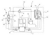
- FIG. FIG. 1 is a diagram showing an overall configuration of an air-conditioning apparatus 1 according to Embodiment 1 of the present invention.
- the air conditioner 1 includes an outdoor unit 2 and an indoor unit 3.
- the air conditioner 1 has a refrigerant in the order of the compressor 4, the four-way valve 5, the outdoor heat exchanger 6, the first expansion valve 7, the refrigerant container 8, the second expansion valve 9, and the indoor heat exchanger 10.
- a refrigerant circuit 12 to which a pipe 11 is connected is provided.
- a compressor 4, a four-way valve 5, an outdoor heat exchanger 6, a first expansion valve 7, a refrigerant container 8 and a second expansion valve 9 are provided as components of the outdoor unit 2.
- the compressor 4 is configured by an inverter compressor or the like capable of capacity control, and sucks low-temperature low-pressure gas refrigerant, compresses it, and discharges it into a high-temperature high-pressure gas refrigerant state.
- the four-way valve 5 is a flow path switching valve that switches the flow direction of the refrigerant.
- the outdoor heat exchanger 6 is composed of, for example, a plate fin heat exchanger, and exchanges heat between the refrigerant and the outdoor air.
- a capillary tube for decompression is connected to the outlet of the outdoor heat exchanger 6.
- the 1st expansion valve 7 is a valve which decompresses a refrigerant
- the refrigerant container 8 is an excess refrigerant storage container that is provided between the first expansion valve 7 and the second expansion valve 9 and stores excess refrigerant.
- the second expansion valve 9 is a valve that depressurizes the refrigerant, and is an electronic expansion valve capable of adjusting the opening degree.
- the outdoor unit 2 includes a temperature sensor 13 for detecting the temperature of the outlet of the compressor 4, a temperature sensor 14 for detecting the temperature at an intermediate position of the pipes constituting the outdoor heat exchanger 6, and the outlet of the outdoor heat exchanger 6.
- a temperature sensor 15 for detecting the temperature is arranged.
- an indoor heat exchanger 10 is provided as a component device of the indoor unit 3.
- the indoor heat exchanger 10 is composed of, for example, a plate fin heat exchanger, and exchanges heat between the refrigerant and the room air.
- the indoor unit 3 includes a temperature sensor 16 that detects the temperature of the inlet of the indoor heat exchanger 10, a temperature sensor 17 that detects the temperature at an intermediate position of the pipes constituting the indoor heat exchanger 10, and the indoor heat exchanger 10.
- a temperature sensor 18 for detecting the temperature at the outlet of the indoor heat exchanger and a temperature sensor 19 for detecting the temperature of the indoor air flowing into the indoor heat exchanger 10 are arranged.
- the refrigerant pipe 11 connecting the refrigerant circuit 12 of the air conditioner 1 is filled with a refrigerant, for example, R410A which is an HFC-type refrigerant, thereby constituting a refrigeration cycle. Further, in the vicinity of the outdoor heat exchanger 6 and the indoor heat exchanger 10, a blower (not shown) for blowing outdoor air or indoor air is arranged.
- a refrigerant for example, R410A which is an HFC-type refrigerant
- the air conditioner 1 controls the outdoor unit 2 to control the air conditioner 1 such as driving an actuator including a first expansion valve 7, a second expansion valve 9, a compressor 4, a four-way valve 5, and a blower. It has a device 20.
- the control device 20 receives detection signals from the various temperature sensors 13 to 19.
- the control device 20 is configured by a microcomputer or a DSP (Digital Signal Processor).
- the control device 20 corresponds to the expansion valve control unit of the present invention.
- the control device 20 acquires necessary temperatures from the various temperature sensors 13 to 19, and adjusts the opening degrees of the first expansion valve 7 and the second expansion valve 9 based on these acquired values. Therefore, the control device 20 stores a program corresponding to the flowcharts of FIGS.
- the control device 20 switches the four-way valve 5 to the cooling operation, the refrigerant is compressed by the compressor 4 to become a high-temperature and high-pressure gas refrigerant and flows into the outdoor heat exchanger 6 through the four-way valve 5.
- the high-temperature and high-pressure gas refrigerant that has flowed into the outdoor heat exchanger 6 is radiated by exchanging heat with outdoor air that passes through the outdoor heat exchanger 6, and flows out as high-pressure liquid refrigerant.
- the high-pressure liquid refrigerant that has flowed out of the outdoor heat exchanger 6 is decompressed by the first expansion valve 7 and the second expansion valve 9, becomes a low-pressure gas-liquid two-phase refrigerant, and flows into the indoor heat exchanger 10.
- the gas-liquid two-phase refrigerant flowing into the indoor heat exchanger 10 is heat-exchanged with the indoor air passing through the indoor heat exchanger 10, and cools the indoor air to become a low-temperature and low-pressure gas refrigerant and sucks it into the compressor 4. Is done.
- the control device 20 switches the four-way valve 5 to the heating operation, the refrigerant is compressed by the compressor 4 to become a high-temperature and high-pressure gas refrigerant in the same manner as described above, and the indoor heat exchanger 10 is passed through the four-way valve 5. Flow into.
- the high-temperature and high-pressure gas refrigerant flowing into the indoor heat exchanger 10 is heat-exchanged with the indoor air passing through the indoor heat exchanger 10, and warms the indoor air to become a high-pressure liquid refrigerant.
- the high-pressure liquid refrigerant that has flowed out of the indoor heat exchanger 10 is decompressed by the second expansion valve 9 and the first expansion valve 7, becomes a low-pressure gas-liquid two-phase refrigerant, and flows into the outdoor heat exchanger 6.
- the low-pressure gas-liquid two-phase refrigerant flowing into the outdoor heat exchanger 6 is heat-exchanged with outdoor air passing through the outdoor heat exchanger 6 and is sucked into the compressor 4 as a low-temperature and low-pressure gas refrigerant.
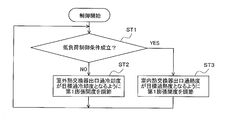
- FIG. 2 is a diagram showing a control flow of the first expansion valve 7 according to Embodiment 1 of the present invention.
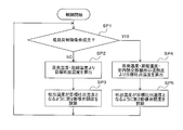
- FIG. 3 is a diagram showing a control flow of the second expansion valve 9 according to Embodiment 1 of the present invention. The control of the first expansion valve 7 and the second expansion valve 9 of the air conditioner 1 will be described based on FIGS.
- the control device 20 is in the cooling operation in steps ST1 and SP1 shown in FIGS. 2 and 3, the difference between the indoor suction temperature and the indoor set temperature is equal to or lower than the temperature reference value, and the operating frequency of the compressor 4 is the frequency. It is determined whether a low load control condition equal to or less than a reference value is satisfied.
- the indoor suction temperature is a detected temperature of the temperature sensor 19 that detects the temperature of the indoor air flowing into the indoor heat exchanger 10.
- the control device 20 is in the cooling operation, and the difference between the indoor suction temperature and the indoor set temperature is larger than the temperature reference value, or the operating frequency of the compressor 4 is larger than the frequency reference value, step ST1, When SP1 is NO, it is determined that the normal control condition is satisfied.
- steps ST1 and SP1 where the normal control condition is satisfied are NO, the process proceeds to steps ST2 and SP2, respectively. Further, the control device 20 is in the cooling operation, and the difference between the indoor suction temperature and the indoor set temperature is equal to or lower than the temperature reference value, and the operation frequency of the compressor 4 is equal to or lower than the frequency reference value. In this case, it is determined that the low load control condition is satisfied. When steps ST1 and SP1 where the low load control condition is satisfied are YES, the process proceeds to steps ST3 and SP4, respectively.
- the control device 20 sets the opening degree of the first expansion valve 7 and the outlet subcooling degree of the outdoor heat exchanger 6 to the target subcooling degree in step ST ⁇ b> 2 where the normal control condition is satisfied. Adjust as follows.
- the outlet subcooling degree of the outdoor heat exchanger 6 detects the temperature of the outlet of the outdoor heat exchanger 6 from the detection temperature of the temperature sensor 14 that detects the temperature of the intermediate position of the pipes constituting the outdoor heat exchanger 6. It is calculated by subtracting the detected temperature of the temperature sensor 15 to be performed. After the process of step ST2, the process returns to step ST1.
- the control device 20 uses the target discharge temperature of the discharge temperature of the compressor 4 as the target discharge temperature of the compressor 4 using the evaporation temperature, the condensation temperature, and the characteristic data of the compressor 4, as shown in FIG.
- the calculation is performed by setting the suction superheat degree of the compressor 4 to a degree greater than 0 degree and within 5 degrees.
- the evaporating temperature is a temperature detected by the temperature sensor 17 that detects the temperature at the intermediate position of the pipe constituting the indoor heat exchanger 10.
- the condensation temperature is a detected temperature of the temperature sensor 14 that detects the temperature at the intermediate position of the piping that constitutes the outdoor heat exchanger 6.
- step SP3 the control device 20 sets the opening of the second expansion valve 9 so that the discharge temperature of the compressor 4 becomes the target discharge temperature calculated in step SP2. Adjust to.
- the discharge temperature of the compressor 4 is the detected temperature of the temperature sensor 13 that detects the temperature of the outlet of the compressor 4. After the process of step SP3, the process returns to step SP1.
- the control device 20 determines the opening degree of the first expansion valve 7 and the degree of superheat at the outlet of the indoor heat exchanger 10 in the normal control condition in step ST3 where the low load control condition is established. Adjust to a higher target superheat. Thereby, the target superheat degree of the outlet superheat degree of the indoor heat exchanger 10 is set higher than the normal control condition, for example, 20 degrees, and the opening degree of the first expansion valve 7 becomes smaller than the normal control condition.
- the degree of superheat at the outlet of the indoor heat exchanger 10 is detected by the temperature sensor 16 that detects the temperature of the inlet of the indoor heat exchanger 10 from the detected temperature of the temperature sensor 18 that detects the temperature of the outlet of the indoor heat exchanger 10. Calculated by subtracting temperature. After step ST3, the process returns to step ST1.
- the control device 20 sets the target discharge temperature of the discharge temperature of the compressor 4 to the evaporation temperature, the condensation temperature, and the indoor heat exchanger 10 in step SP4 where the low load control condition is satisfied. It is calculated from the outlet superheat degree and the characteristic data of the compressor 4.
- the outlet superheat degree of the indoor heat exchanger 10 is, for example, 20 degrees, and is used when it is equal to the suction superheat degree of the compressor 4.
- the target discharge temperature of the discharge temperature of the compressor 4 is calculated higher than the normal control condition, and the opening degree of the second expansion valve 9 becomes smaller than the normal control condition.
- the evaporating temperature is a temperature detected by the temperature sensor 17 that detects the temperature at the intermediate position of the pipe constituting the indoor heat exchanger 10.
- the condensation temperature is a detected temperature of the temperature sensor 14 that detects the temperature at the intermediate position of the piping that constitutes the outdoor heat exchanger 6.
- the degree of superheat at the outlet of the indoor heat exchanger 10 is obtained by subtracting the detected temperature of the temperature sensor 16 that detects the temperature of the inlet of the indoor heat exchanger 10 from the detected temperature of the temperature sensor 18 that detects the temperature of the outlet of the indoor heat exchanger 10. Is calculated.
- step SP5 the control device 20 sets the opening of the second expansion valve 9 so that the discharge temperature of the compressor 4 becomes the target discharge temperature calculated in step SP4. Adjust to. After the process of step SP5, the process returns to step SP1.
- the target superheat degree of the outlet superheat degree of the indoor heat exchanger 10 is increased to be the first.
- the opening degree of the expansion valve 7 is reduced.
- the target discharge temperature of the compressor 4 used for adjusting the opening degree of the second expansion valve 9 is the indoor heat exchanger 10. This is calculated by replacing the outlet superheat degree with the suction superheat degree of the compressor 4.
- the target discharge temperature of the discharge temperature of the compressor 4 becomes higher than the normal control condition, and the opening degree of the second expansion valve 9 is reduced. Therefore, it is possible to prevent the opening of the second expansion valve 9 from being increased in conjunction with the opening of the first expansion valve 7 being reduced, and to prevent the effect of reducing the air conditioning capability from being negated. .
- the target discharge temperature of the compressor 4 is higher than the normal control condition, and the discharge temperature of the compressor 4 is normally controlled. Stable at a higher value than the conditions.
- the air conditioner 1 according to Embodiment 1 can reduce the frequency of the thermo-off that stops the compressor 4 even when the air-conditioning is under a low load, for example, when used for a long operation time such as mechanical cooling.
- the life of the compressor 4 can be extended.
- the control device 20 has a low load control condition in which the difference between the indoor suction temperature and the indoor set temperature is equal to or lower than the temperature reference value and the operating frequency of the compressor 4 is equal to or lower than the frequency reference value. Further, the opening degree of the first expansion valve 7 is adjusted so that the outlet superheat degree of the indoor heat exchanger 10 becomes the target superheat degree, and the opening degree of the second expansion valve 9 is changed to the discharge temperature of the compressor 4. Is adjusted to the target discharge temperature. According to this configuration, the opening degree of the first expansion valve 7 and the second expansion valve 9 can be reduced for each purpose under low load control conditions.
- the target discharge temperature of the compressor 4 is higher than the normal control condition, and the discharge temperature of the compressor 4 is higher than the normal control condition. Also stabilizes at higher values. For this reason, the fluctuation
- the control device 20 opens the first expansion valve 7 in a low load control condition where the difference between the indoor suction temperature and the indoor set temperature is equal to or lower than the temperature reference value and the operating frequency of the compressor 4 is equal to or lower than the frequency reference value.
- the degree is adjusted to be smaller than the normal control condition, and the opening degree of the second expansion valve 9 is adjusted to be smaller than the normal control condition. According to this configuration, the opening degree of the first expansion valve 7 and the second expansion valve 9 can be reduced for each purpose under low load control conditions.
- the control device 20 opens the first expansion valve 7 in a low load control condition where the difference between the indoor suction temperature and the indoor set temperature is equal to or lower than the temperature reference value and the operating frequency of the compressor 4 is equal to or lower than the frequency reference value.
- the outlet superheat degree of the indoor heat exchanger 10 is adjusted to a target superheat degree higher than the normal control condition, and the opening degree of the second expansion valve 9 is adjusted so that the discharge temperature of the compressor 4 is normal.
- the target discharge temperature is adjusted to be higher than the control condition. According to this configuration, the opening degree of the first expansion valve 7 and the second expansion valve 9 can be reduced for each purpose under low load control conditions.
- the control device 20 opens the first expansion valve 7 in a low load control condition where the difference between the indoor suction temperature and the indoor set temperature is equal to or lower than the temperature reference value and the operating frequency of the compressor 4 is equal to or lower than the frequency reference value.
- the outlet superheat degree of the indoor heat exchanger 10 is adjusted to a target superheat degree higher than the normal control condition, and the opening degree of the second expansion valve 9 is adjusted so that the discharge temperature of the compressor 4 is Adjustment is made so that the target discharge temperature is higher than the normal control condition calculated by replacing the suction superheat degree of the compressor 4 with the outlet superheat degree of the indoor heat exchanger 10 being equal. According to this configuration, the opening degree of the first expansion valve 7 and the second expansion valve 9 can be reduced for each purpose under low load control conditions.
- the target discharge temperature of the compressor 4 is higher than the normal control condition, and the discharge temperature of the compressor 4 is higher than the normal control condition. Also stabilizes at higher values. For this reason, the fluctuation
- the control device 20 controls the first expansion valve 7. Is adjusted so that the outlet supercooling degree of the outdoor heat exchanger 6 becomes the target supercooling degree, and the opening degree of the second expansion valve 9 is adjusted by the discharge temperature of the compressor 4.
- the suction superheat degree is set to be larger than 0 degrees and within 5 degrees so that the target discharge temperature is calculated. According to this configuration, the first expansion valve 7 and the second expansion valve 9 can be appropriately controlled under normal control conditions.
- the air conditioner that can perform both the cooling operation and the heating operation has been described.
- the present invention is control during cooling operation, it can also be applied to an air conditioner that performs only cooling operation.
Landscapes
- Engineering & Computer Science (AREA)
- Physics & Mathematics (AREA)
- Mechanical Engineering (AREA)
- Thermal Sciences (AREA)
- General Engineering & Computer Science (AREA)
- Air Conditioning Control Device (AREA)
Priority Applications (3)
| Application Number | Priority Date | Filing Date | Title |
|---|---|---|---|
| EP15868656.8A EP3147587B1 (de) | 2015-07-27 | 2015-07-27 | Klimatierungsvorrichtung |
| JP2017530504A JP6320639B2 (ja) | 2015-07-27 | 2015-07-27 | 空気調和装置 |
| PCT/JP2015/071273 WO2017017767A1 (ja) | 2015-07-27 | 2015-07-27 | 空気調和装置 |
Applications Claiming Priority (1)
| Application Number | Priority Date | Filing Date | Title |
|---|---|---|---|
| PCT/JP2015/071273 WO2017017767A1 (ja) | 2015-07-27 | 2015-07-27 | 空気調和装置 |
Publications (1)
| Publication Number | Publication Date |
|---|---|
| WO2017017767A1 true WO2017017767A1 (ja) | 2017-02-02 |
Family
ID=57884249
Family Applications (1)
| Application Number | Title | Priority Date | Filing Date |
|---|---|---|---|
| PCT/JP2015/071273 Ceased WO2017017767A1 (ja) | 2015-07-27 | 2015-07-27 | 空気調和装置 |
Country Status (3)
| Country | Link |
|---|---|
| EP (1) | EP3147587B1 (de) |
| JP (1) | JP6320639B2 (de) |
| WO (1) | WO2017017767A1 (de) |
Cited By (11)
| Publication number | Priority date | Publication date | Assignee | Title |
|---|---|---|---|---|
| CN110966711A (zh) * | 2018-09-29 | 2020-04-07 | 青岛海尔空调器有限总公司 | 电子膨胀阀目标排气温度的确定方法和装置 |
| CN111271848A (zh) * | 2019-07-17 | 2020-06-12 | 宁波奥克斯电气股份有限公司 | 一种空调器的控制方法及其空调器 |
| CN111928419A (zh) * | 2020-07-14 | 2020-11-13 | 青岛海尔空调电子有限公司 | 多联机空调机组的控制方法及系统 |
| CN113302440A (zh) * | 2019-01-17 | 2021-08-24 | 三电汽车空调系统株式会社 | 车用空调装置 |
| WO2021214931A1 (ja) * | 2020-04-23 | 2021-10-28 | 日立ジョンソンコントロールズ空調株式会社 | 空気調和システムおよび制御方法 |
| JPWO2021255921A1 (de) * | 2020-06-19 | 2021-12-23 | ||
| CN115031349A (zh) * | 2022-07-19 | 2022-09-09 | 广东欧科空调制冷有限公司 | 一种多联式空调膨胀阀故障系统过热度安全的控制方法 |
| CN115711472A (zh) * | 2022-11-28 | 2023-02-24 | 珠海格力电器股份有限公司 | 空调控制方法和控制装置、空调系统及存储介质 |
| CN116085950A (zh) * | 2022-11-28 | 2023-05-09 | 珠海格力电器股份有限公司 | 节能控制方法和控制装置、空调系统及存储介质 |
| WO2024045636A1 (zh) * | 2022-08-27 | 2024-03-07 | 广东美的暖通设备有限公司 | 温度调节方法、电控盒、防凝露的控制方法和空调器 |
| JP2026068934A (ja) * | 2024-10-11 | 2026-04-23 | 広東美的制冷設備有限公司 | 空気調和装置 |
Families Citing this family (6)
| Publication number | Priority date | Publication date | Assignee | Title |
|---|---|---|---|---|
| CN111164355B (zh) * | 2017-10-10 | 2024-01-05 | 三菱电机株式会社 | 空调装置 |
| CN113375319A (zh) * | 2020-02-25 | 2021-09-10 | 青岛海尔空调电子有限公司 | 制冷状态下定频空调的控制方法 |
| CN111397142B (zh) * | 2020-04-16 | 2022-02-22 | 宁波奥克斯电气股份有限公司 | 空调器电子膨胀阀的控制方法、装置、空调器及存储介质 |
| CN112161390B (zh) * | 2020-09-15 | 2021-11-02 | 珠海格力电器股份有限公司 | 电子膨胀阀控制方法、装置和空调 |
| CN116358101A (zh) * | 2023-03-23 | 2023-06-30 | 浙江中广电器集团股份有限公司 | 一种电子膨胀阀的开度控制方法 |
| CN119492140B (zh) * | 2023-08-15 | 2025-09-23 | 海信空调有限公司 | 空调器 |
Citations (5)
| Publication number | Priority date | Publication date | Assignee | Title |
|---|---|---|---|---|
| JP2007263383A (ja) * | 2006-03-27 | 2007-10-11 | Daikin Ind Ltd | 冷凍装置 |
| JP2010249452A (ja) | 2009-04-17 | 2010-11-04 | Mitsubishi Electric Corp | 空気調和装置 |
| JP2014190632A (ja) * | 2013-03-27 | 2014-10-06 | Hitachi Appliances Inc | 空気調和機、および空気調和機の運転方法 |
| JP2014240714A (ja) * | 2013-06-11 | 2014-12-25 | ダイキン工業株式会社 | 空気調和装置 |
| JP2015087065A (ja) * | 2013-10-31 | 2015-05-07 | シャープ株式会社 | 空気調和機 |
Family Cites Families (3)
| Publication number | Priority date | Publication date | Assignee | Title |
|---|---|---|---|---|
| WO2007110908A1 (ja) * | 2006-03-27 | 2007-10-04 | Mitsubishi Denki Kabushiki Kaisha | 冷凍空調装置 |
| EP2077427B1 (de) * | 2008-01-02 | 2017-03-15 | LG Electronics Inc. | Klimaanlagensystem |
| JP5533491B2 (ja) * | 2010-09-24 | 2014-06-25 | パナソニック株式会社 | 冷凍サイクル装置及び温水暖房装置 |
-
2015
- 2015-07-27 EP EP15868656.8A patent/EP3147587B1/de not_active Not-in-force
- 2015-07-27 JP JP2017530504A patent/JP6320639B2/ja active Active
- 2015-07-27 WO PCT/JP2015/071273 patent/WO2017017767A1/ja not_active Ceased
Patent Citations (5)
| Publication number | Priority date | Publication date | Assignee | Title |
|---|---|---|---|---|
| JP2007263383A (ja) * | 2006-03-27 | 2007-10-11 | Daikin Ind Ltd | 冷凍装置 |
| JP2010249452A (ja) | 2009-04-17 | 2010-11-04 | Mitsubishi Electric Corp | 空気調和装置 |
| JP2014190632A (ja) * | 2013-03-27 | 2014-10-06 | Hitachi Appliances Inc | 空気調和機、および空気調和機の運転方法 |
| JP2014240714A (ja) * | 2013-06-11 | 2014-12-25 | ダイキン工業株式会社 | 空気調和装置 |
| JP2015087065A (ja) * | 2013-10-31 | 2015-05-07 | シャープ株式会社 | 空気調和機 |
Non-Patent Citations (1)
| Title |
|---|
| See also references of EP3147587A4 |
Cited By (15)
| Publication number | Priority date | Publication date | Assignee | Title |
|---|---|---|---|---|
| CN110966711A (zh) * | 2018-09-29 | 2020-04-07 | 青岛海尔空调器有限总公司 | 电子膨胀阀目标排气温度的确定方法和装置 |
| CN113302440B (zh) * | 2019-01-17 | 2022-12-23 | 三电株式会社 | 车用空调装置 |
| CN113302440A (zh) * | 2019-01-17 | 2021-08-24 | 三电汽车空调系统株式会社 | 车用空调装置 |
| CN111271848A (zh) * | 2019-07-17 | 2020-06-12 | 宁波奥克斯电气股份有限公司 | 一种空调器的控制方法及其空调器 |
| WO2021214931A1 (ja) * | 2020-04-23 | 2021-10-28 | 日立ジョンソンコントロールズ空調株式会社 | 空気調和システムおよび制御方法 |
| WO2021255921A1 (ja) * | 2020-06-19 | 2021-12-23 | 三菱電機株式会社 | 冷凍サイクル装置 |
| JPWO2021255921A1 (de) * | 2020-06-19 | 2021-12-23 | ||
| JP7301230B2 (ja) | 2020-06-19 | 2023-06-30 | 三菱電機株式会社 | 冷凍サイクル装置 |
| CN111928419A (zh) * | 2020-07-14 | 2020-11-13 | 青岛海尔空调电子有限公司 | 多联机空调机组的控制方法及系统 |
| CN111928419B (zh) * | 2020-07-14 | 2023-03-31 | 青岛海尔空调电子有限公司 | 多联机空调机组的控制方法及系统 |
| CN115031349A (zh) * | 2022-07-19 | 2022-09-09 | 广东欧科空调制冷有限公司 | 一种多联式空调膨胀阀故障系统过热度安全的控制方法 |
| WO2024045636A1 (zh) * | 2022-08-27 | 2024-03-07 | 广东美的暖通设备有限公司 | 温度调节方法、电控盒、防凝露的控制方法和空调器 |
| CN115711472A (zh) * | 2022-11-28 | 2023-02-24 | 珠海格力电器股份有限公司 | 空调控制方法和控制装置、空调系统及存储介质 |
| CN116085950A (zh) * | 2022-11-28 | 2023-05-09 | 珠海格力电器股份有限公司 | 节能控制方法和控制装置、空调系统及存储介质 |
| JP2026068934A (ja) * | 2024-10-11 | 2026-04-23 | 広東美的制冷設備有限公司 | 空気調和装置 |
Also Published As
| Publication number | Publication date |
|---|---|
| EP3147587B1 (de) | 2018-03-21 |
| JPWO2017017767A1 (ja) | 2017-10-19 |
| JP6320639B2 (ja) | 2018-05-09 |
| EP3147587A4 (de) | 2017-05-03 |
| EP3147587A1 (de) | 2017-03-29 |
Similar Documents
| Publication | Publication Date | Title |
|---|---|---|
| JP6320639B2 (ja) | 空気調和装置 | |
| CN109804209B (zh) | 空调装置 | |
| US8020395B2 (en) | Air conditioning apparatus | |
| US8572995B2 (en) | Refrigeration system | |
| US8522568B2 (en) | Refrigeration system | |
| JP6595205B2 (ja) | 冷凍サイクル装置 | |
| US11022354B2 (en) | Air conditioner | |
| EP2375188A1 (de) | Klimaanlage | |
| CN109790995B (zh) | 空调装置 | |
| CN111486574B (zh) | 空调系统及其防凝露控制方法和装置、存储介质 | |
| JP6388010B2 (ja) | 空気調和装置 | |
| US12173922B2 (en) | Sequential hot gas reheat system in an air conditioning unit | |
| JP5979112B2 (ja) | 冷凍装置 | |
| JP5673738B2 (ja) | 空気調和装置 | |
| WO2016194098A1 (ja) | 空気調和装置及び運転制御装置 | |
| CN107238161B (zh) | 多联机系统及其模式切换控制方法 | |
| WO2016098645A1 (ja) | 空気調和装置 | |
| WO2015182484A1 (ja) | 冷凍装置 | |
| JP7467827B2 (ja) | 空気調和機 | |
| JP4176677B2 (ja) | 空気調和機 | |
| JP2018146169A (ja) | 空調機 | |
| WO2022059136A1 (ja) | 冷凍サイクル装置 | |
| JP7204947B2 (ja) | 空気調和装置 | |
| WO2024127571A1 (ja) | 冷凍サイクル装置 | |
| JP2024036963A (ja) | 冷凍サイクル装置 |
Legal Events
| Date | Code | Title | Description |
|---|---|---|---|
| REEP | Request for entry into the european phase |
Ref document number: 2015868656 Country of ref document: EP |
|
| WWE | Wipo information: entry into national phase |
Ref document number: 2015868656 Country of ref document: EP |
|
| 121 | Ep: the epo has been informed by wipo that ep was designated in this application |
Ref document number: 15868656 Country of ref document: EP Kind code of ref document: A1 |
|
| ENP | Entry into the national phase |
Ref document number: 2017530504 Country of ref document: JP Kind code of ref document: A |
|
| NENP | Non-entry into the national phase |
Ref country code: DE |