WO2017017866A1 - Station de base, terminal, procédé de réception et procédé d'émission - Google Patents
Station de base, terminal, procédé de réception et procédé d'émission Download PDFInfo
- Publication number
- WO2017017866A1 WO2017017866A1 PCT/JP2016/001293 JP2016001293W WO2017017866A1 WO 2017017866 A1 WO2017017866 A1 WO 2017017866A1 JP 2016001293 W JP2016001293 W JP 2016001293W WO 2017017866 A1 WO2017017866 A1 WO 2017017866A1
- Authority
- WO
- WIPO (PCT)
- Prior art keywords
- signal
- subframes
- subframe
- transmission
- srs
- Prior art date
- Legal status (The legal status is an assumption and is not a legal conclusion. Google has not performed a legal analysis and makes no representation as to the accuracy of the status listed.)
- Ceased
Links
Images






Classifications
-
- H—ELECTRICITY
- H04—ELECTRIC COMMUNICATION TECHNIQUE
- H04L—TRANSMISSION OF DIGITAL INFORMATION, e.g. TELEGRAPHIC COMMUNICATION
- H04L5/00—Arrangements affording multiple use of the transmission path
- H04L5/003—Arrangements for allocating sub-channels of the transmission path
- H04L5/0048—Allocation of pilot signals, i.e. of signals known to the receiver
-
- H—ELECTRICITY
- H04—ELECTRIC COMMUNICATION TECHNIQUE
- H04W—WIRELESS COMMUNICATION NETWORKS
- H04W4/00—Services specially adapted for wireless communication networks; Facilities therefor
- H04W4/70—Services for machine-to-machine communication [M2M] or machine type communication [MTC]
-
- H—ELECTRICITY
- H04—ELECTRIC COMMUNICATION TECHNIQUE
- H04B—TRANSMISSION
- H04B7/00—Radio transmission systems, i.e. using radiation field
- H04B7/02—Diversity systems; Multi-antenna system, i.e. transmission or reception using multiple antennas
- H04B7/04—Diversity systems; Multi-antenna system, i.e. transmission or reception using multiple antennas using two or more spaced independent antennas
- H04B7/06—Diversity systems; Multi-antenna system, i.e. transmission or reception using multiple antennas using two or more spaced independent antennas at the transmitting station
- H04B7/0613—Diversity systems; Multi-antenna system, i.e. transmission or reception using multiple antennas using two or more spaced independent antennas at the transmitting station using simultaneous transmission
- H04B7/0615—Diversity systems; Multi-antenna system, i.e. transmission or reception using multiple antennas using two or more spaced independent antennas at the transmitting station using simultaneous transmission of weighted versions of same signal
- H04B7/0619—Diversity systems; Multi-antenna system, i.e. transmission or reception using multiple antennas using two or more spaced independent antennas at the transmitting station using simultaneous transmission of weighted versions of same signal using feedback from receiving side
- H04B7/0658—Feedback reduction
- H04B7/066—Combined feedback for a number of channels, e.g. over several subcarriers like in orthogonal frequency division multiplexing [OFDM]
-
- H—ELECTRICITY
- H04—ELECTRIC COMMUNICATION TECHNIQUE
- H04J—MULTIPLEX COMMUNICATION
- H04J13/00—Code division multiplex systems
- H04J13/0007—Code type
- H04J13/004—Orthogonal
-
- H—ELECTRICITY
- H04—ELECTRIC COMMUNICATION TECHNIQUE
- H04J—MULTIPLEX COMMUNICATION
- H04J13/00—Code division multiplex systems
- H04J13/16—Code allocation
- H04J13/18—Allocation of orthogonal codes
-
- H—ELECTRICITY
- H04—ELECTRIC COMMUNICATION TECHNIQUE
- H04L—TRANSMISSION OF DIGITAL INFORMATION, e.g. TELEGRAPHIC COMMUNICATION
- H04L1/00—Arrangements for detecting or preventing errors in the information received
- H04L1/08—Arrangements for detecting or preventing errors in the information received by repeating transmission, e.g. Verdan system
-
- H—ELECTRICITY
- H04—ELECTRIC COMMUNICATION TECHNIQUE
- H04L—TRANSMISSION OF DIGITAL INFORMATION, e.g. TELEGRAPHIC COMMUNICATION
- H04L25/00—Baseband systems
- H04L25/02—Details ; arrangements for supplying electrical power along data transmission lines
- H04L25/0202—Channel estimation
- H04L25/0204—Channel estimation of multiple channels
-
- H—ELECTRICITY
- H04—ELECTRIC COMMUNICATION TECHNIQUE
- H04L—TRANSMISSION OF DIGITAL INFORMATION, e.g. TELEGRAPHIC COMMUNICATION
- H04L25/00—Baseband systems
- H04L25/02—Details ; arrangements for supplying electrical power along data transmission lines
- H04L25/0202—Channel estimation
- H04L25/0224—Channel estimation using sounding signals
-
- H—ELECTRICITY
- H04—ELECTRIC COMMUNICATION TECHNIQUE
- H04L—TRANSMISSION OF DIGITAL INFORMATION, e.g. TELEGRAPHIC COMMUNICATION
- H04L27/00—Modulated-carrier systems
- H04L27/26—Systems using multi-frequency codes
- H04L27/2601—Multicarrier modulation systems
- H04L27/2602—Signal structure
-
- H—ELECTRICITY
- H04—ELECTRIC COMMUNICATION TECHNIQUE
- H04L—TRANSMISSION OF DIGITAL INFORMATION, e.g. TELEGRAPHIC COMMUNICATION
- H04L27/00—Modulated-carrier systems
- H04L27/26—Systems using multi-frequency codes
- H04L27/2601—Multicarrier modulation systems
- H04L27/2602—Signal structure
- H04L27/26035—Maintenance of orthogonality, e.g. for signals exchanged between cells or users, or by using covering codes or sequences
-
- H—ELECTRICITY
- H04—ELECTRIC COMMUNICATION TECHNIQUE
- H04L—TRANSMISSION OF DIGITAL INFORMATION, e.g. TELEGRAPHIC COMMUNICATION
- H04L27/00—Modulated-carrier systems
- H04L27/26—Systems using multi-frequency codes
- H04L27/2601—Multicarrier modulation systems
- H04L27/2626—Arrangements specific to the transmitter only
- H04L27/2627—Modulators
- H04L27/2643—Modulators using symbol repetition, e.g. time domain realization of distributed FDMA
-
- H—ELECTRICITY
- H04—ELECTRIC COMMUNICATION TECHNIQUE
- H04L—TRANSMISSION OF DIGITAL INFORMATION, e.g. TELEGRAPHIC COMMUNICATION
- H04L5/00—Arrangements affording multiple use of the transmission path
- H04L5/0001—Arrangements for dividing the transmission path
- H04L5/0003—Two-dimensional division
- H04L5/0005—Time-frequency
- H04L5/0007—Time-frequency the frequencies being orthogonal, e.g. OFDM(A) or DMT
- H04L5/001—Time-frequency the frequencies being orthogonal, e.g. OFDM(A) or DMT the frequencies being arranged in component carriers
-
- H—ELECTRICITY
- H04—ELECTRIC COMMUNICATION TECHNIQUE
- H04L—TRANSMISSION OF DIGITAL INFORMATION, e.g. TELEGRAPHIC COMMUNICATION
- H04L5/00—Arrangements affording multiple use of the transmission path
- H04L5/003—Arrangements for allocating sub-channels of the transmission path
- H04L5/0048—Allocation of pilot signals, i.e. of signals known to the receiver
- H04L5/0051—Allocation of pilot signals, i.e. of signals known to the receiver of dedicated pilots, i.e. pilots destined for a single user or terminal
-
- H—ELECTRICITY
- H04—ELECTRIC COMMUNICATION TECHNIQUE
- H04L—TRANSMISSION OF DIGITAL INFORMATION, e.g. TELEGRAPHIC COMMUNICATION
- H04L5/00—Arrangements affording multiple use of the transmission path
- H04L5/003—Arrangements for allocating sub-channels of the transmission path
- H04L5/0058—Allocation criteria
- H04L5/0062—Avoidance of ingress interference, e.g. ham radio channels
-
- H—ELECTRICITY
- H04—ELECTRIC COMMUNICATION TECHNIQUE
- H04L—TRANSMISSION OF DIGITAL INFORMATION, e.g. TELEGRAPHIC COMMUNICATION
- H04L5/00—Arrangements affording multiple use of the transmission path
- H04L5/0091—Signalling for the administration of the divided path, e.g. signalling of configuration information
- H04L5/0094—Indication of how sub-channels of the path are allocated
-
- H—ELECTRICITY
- H04—ELECTRIC COMMUNICATION TECHNIQUE
- H04W—WIRELESS COMMUNICATION NETWORKS
- H04W72/00—Local resource management
- H04W72/20—Control channels or signalling for resource management
-
- H—ELECTRICITY
- H04—ELECTRIC COMMUNICATION TECHNIQUE
- H04L—TRANSMISSION OF DIGITAL INFORMATION, e.g. TELEGRAPHIC COMMUNICATION
- H04L1/00—Arrangements for detecting or preventing errors in the information received
- H04L1/12—Arrangements for detecting or preventing errors in the information received by using return channel
- H04L1/16—Arrangements for detecting or preventing errors in the information received by using return channel in which the return channel carries supervisory signals, e.g. repetition request signals
- H04L1/1607—Details of the supervisory signal
- H04L1/1671—Details of the supervisory signal the supervisory signal being transmitted together with control information
Definitions
- FIG. 1 shows an example of subframe configuration in an LTE uplink shared channel (PUSCH: Physical Uplink Shared Channel).
- PUSCH Physical Uplink Shared Channel
- PUSCH Physical Uplink Shared Channel
- PUSCH Physical Uplink Shared Channel
- DMRS Demodulation Reference Signal
- the base station receives the PUSCH, the base station performs channel estimation using DMRS. Thereafter, the base station demodulates and decodes the SC-FDMA data symbol using the channel estimation result.
- HARQ Hybrid Automatic Repeat Request
- the terminal feeds back a response signal indicating the downlink data error detection result to the base station.
- the terminal performs CRC (Cyclic Redundancy Check) on the downlink data, and if there is no error in the CRC calculation result, it gives an acknowledgment (ACK: Acknowledgement), and if there is an error in the CRC calculation result, a negative response (NACK: Negative Negative Acknowledgment) is fed back to the base station as a response signal.
- An uplink control channel such as PUCCH (Physical Uplink Control Channel) is used for feedback of this response signal (that is, ACK / NACK signal).
- PUCCH Physical Uplink Control Channel
- a plurality of ACK / NACK signals transmitted from a plurality of terminals are spread by a ZAC (Zero-Auto-correlation) sequence having a Zero-Auto-correlation characteristic on the time axis (ZAC sequence).
- ZAC sequence Zero-Auto-correlation characteristic on the time axis
- code-multiplexed in PUCCH In FIG. 2, (W (0), W (1), W (2), W (3)) represents a Walsh sequence having a sequence length of 4, and (F (0), F (1), F (2)) represents a DFT (Discrete Fourier Transform) sequence having a sequence length of 3.
- the ACK / NACK signal is first spread to the frequency component corresponding to the 1SC-FDMA symbol by the ZAC sequence (sequence length 12) on the frequency axis. That is, a ZAC sequence having a sequence length of 12 is multiplied by an ACK / NACK signal component represented by a complex number.
- the first spread ACK / NACK signal and the ZAC sequence as a reference signal are a Walsh sequence (sequence length 4: W (0) to W (3)) and a DFT sequence (sequence length 3: F), respectively. Second-order diffusion is performed by (0) to F (2)).
- an orthogonal code sequence (OCC: Orthogonal Cover Code, Walsh sequence or DFT sequence) for each component of a sequence length 12 signal (ACK / NACK signal after first spreading or ZAC sequence as a reference signal) )
- OCC Orthogonal Cover Code, Walsh sequence or DFT sequence
- the second-order spread signal is converted into a signal having a sequence length of 12 on the time axis by inverse discrete Fourier transform (IDFT: Inverse Discrete Fourier Transform) or IFFT: Inverse Fast Fourier Transform.
- IDFT Inverse Discrete Fourier Transform
- IFFT Inverse Fast Fourier Transform
- PUCCH is assigned to each terminal in subframe units.
- ACK / NACK signals from different terminals are spread using ZAC sequences defined by different cyclic shift amounts (Cyclic Shift Index) or orthogonal code sequences corresponding to different sequence numbers (OC Index: Orthogonal Cover Index) (Multiplication).
- An orthogonal code sequence is a set of a Walsh sequence and a DFT sequence.
- the orthogonal code sequence may be referred to as a block-wise spreading code sequence. Therefore, the base station can separate a plurality of these code-multiplexed ACK / NACK signals by using conventional despreading and correlation processing (see, for example, Non-Patent Document 4).
- SRS Sounding Reference Signal
- the SRS is mapped to the SRS resource and transmitted from the terminal to the base station.
- the base station sets up an SRS resource candidate group including SRS resource candidates common to all terminals existing in the target cell by cell-specific higher layer notification.
- SRS resources which are subsets of SRS resource candidate groups, are allocated to the allocation target terminals of the SRS resources by higher layer notification in units of terminals.
- the terminal maps the SRS to the allocated SRS resource and transmits it to the base station.
- Each SRS resource candidate is a final SC-FDMA symbol in a subframe (SRS transmission candidate subframe) that is a transmission candidate for SRS.
- SRS transmission candidate subframe a subframe that is a transmission candidate for SRS.
- PUSCH signal the data signal
- Shortened PUCCH format In LTE, when SRS and PUCCH are present in the same symbol, “Shortened PUCCH format” is defined in which PUCCH is spread with six symbols excluding the last symbol of the second half slot, orthogonalized, and transmitted (for example, (Refer nonpatent literature 1).
- Shortened PUCCH format the first spread ACK / NACK signal is secondarily spread by a DFT sequence (sequence length 3: F (0) to F (2)).
- srs-SubframeConfig In LTE, srs-SubframeConfig or the like is defined as a cell-specific upper layer notification for setting an SRS resource candidate group (see, for example, Non-Patent Document 1).
- FIG. 4 shows an example of the definition of srs-SubframeConfig.
- M2M Machine-to-Machine
- a smart grid is a specific application example of the M2M system.
- a smart grid is an infrastructure system that efficiently supplies lifelines such as electricity or gas, and is autonomous and effective by implementing M2M communication between a smart meter deployed in each home or building and a central server. Adjust the balance of demand for resources.
- Other application examples of the M2M communication system include a monitoring system for goods management, environmental sensing or telemedicine, and remote management of vending machine inventory or billing.
- MTC Machine Type Communication
- the base station When the number of subframes (X), which is a unit in which multi-subframe channel estimation and symbol level synthesis are performed, is smaller than the number of repetitions (N Rep ), the base station performs (N Rep / X) symbols after demodulation and decoding Is synthesized.
- Non-Patent Document 6 By using multiple subframe channel estimation and symbol level synthesis, the transmission quality of PUSCH and PUCCH can be improved compared to simple repetition that performs channel estimation and SC-FDMA data symbol demodulation / decoding in units of subframes. (For example, see Non-Patent Document 6).
- MTC terminals In a cell that supports MTC terminals, it is necessary for MTC terminals to coexist with existing LTE terminals, and it is desirable to support MTC terminals so as to minimize the impact on existing LTE systems. . Therefore, in uplink transmission (for example, PUSCH transmission) of an MTC terminal (MTC coverage extension terminal) that requires repetition transmission, in order to prevent collision with the SRS of the existing LTE system, data transmission is performed in the SRS resource candidate. Not performed. This prevents a collision between the SRS and the data signal of the MTC coverage extension terminal.
- uplink transmission for example, PUSCH transmission
- MTC coverage extension terminal MTC coverage extension terminal
- One is a method of puncturing the final SC-FDMA symbol which is an SRS resource candidate after mapping data to 12SC-FDMA symbols excluding DMRS as shown in FIG.
- the symbols other than the final SC-FDMA symbol transmit the same signal in the SRS transmission candidate subframe and other subframes, in-phase combining can be easily realized on the base station side.
- the following two methods can be considered as a format in which a terminal transmits an ACK / NACK signal in an SRS transmission candidate subframe.
- SRS resource candidates Is a method of puncturing the last SC-FDMA symbol.
- a part of the OCC is punctured, so that the orthogonality between OCC sequences is lost, and the characteristics may be deteriorated due to intersymbol interference.
- a terminal includes a repetition unit that repeats an uplink signal over a plurality of subframes to generate a repetition signal, and an uplink reception quality in the plurality of subframes.
- a sounding reference signal (SRS) transmission candidate subframe used for measurement of the first subframe is not included, a first transmission format is set in all of the plurality of subframes, and the transmission is included in the plurality of subframes.
- a configuration comprising a control unit that sets a second transmission format in all of the plurality of subframes when a candidate subframe is included, and a transmission unit that transmits the repetition signal in the set transmission format Take.
- a terminal 200 (MTC coverage extension terminal) to which the MTC coverage extension mode is applied exists in the cell of the base station 100.
- the terminal 200 applies the technique for improving the channel estimation accuracy described above.
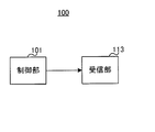
- FIG. 7 is a block diagram illustrating a main configuration of the base station 100 according to the embodiment of the present disclosure.
- the control unit 101 when the SRS transmission candidate subframe is not included in the plurality of subframes in which the uplink signal is repeated, the control unit 101 includes the first in all the plurality of subframes.
- the second transmission format is set in all of the plurality of subframes, and the receiving unit 113 sets the set transmission format. Receive a repetition signal in format.
- FIG. 8 is a block diagram showing a main configuration of the terminal 200 according to each embodiment of the present disclosure.
- repetition section 213 repeats the uplink signal over a plurality of subframes to generate a repetition signal
- control section 209 includes SRS in the plurality of subframes.
- the transmission candidate subframe is not included, the first transmission format is set in all of the plurality of subframes.
- the SRS transmission candidate subframe is included in the plurality of subframes, all of the plurality of subframes are included.
- the transmission unit 217 transmits a repetition signal in the set transmission format.
- the control unit 101 determines the SRS resource candidate group in the cell in consideration of the amount of SRS resources necessary for each of a plurality of existing LTE terminals existing in the cell covered by the base station 100, and determines the determined SRS resource candidate Information indicating the group is output to the control signal generation unit 102.
- the SRS resource candidate group is selected from the table shown in FIG.
- control unit 101 determines the PUCCH format of each subframe in the PUCCH repetition based on the information related to the determined SRS resource candidate group, and outputs information indicating the determined PUCCH format to the combining unit 116.
- control unit 101 determines PDSCH allocation to the MTC coverage extension terminal. At this time, the control unit 101 determines a frequency allocation resource and a modulation / coding method to be instructed to the MTC coverage extension terminal, and outputs information on the determined parameter to the control signal generation unit 102.
- control unit 101 determines the encoding level for the control signal, and outputs the determined encoding level to the control signal encoding unit 103.
- control unit 101 determines a radio resource (downlink resource) for mapping the control signal and downlink data, and outputs information on the determined radio resource to the signal allocation unit 108.
- control unit 101 determines a coding rate used when transmitting downlink data (transmission data) to the resource allocation target terminal 200 and outputs the determined coding rate to the data coding unit 105. .
- control unit 101 determines the coverage extension level of the MTC coverage extension terminal, and determines the information related to the determined coverage extension level or the number of times of repetition necessary for PUCCH transmission at the determined coverage extension level. 102 and the combining unit 116. Further, the control unit 101 generates information on the value of the parameter X used by the MTC coverage extension terminal for PUCCH repetition based on the information on the coverage extension level or the number of repetitions necessary for PUCCH transmission, and controls the generated information. Output to the signal generation unit 102.
- control unit 101 determines resources (cyclic shift, orthogonal code sequence, frequency) for the terminal 200 to transmit PUCCH.
- the control unit 101 outputs a cyclic shift amount and an orthogonal code sequence that may be used for PUCCH transmission to the despreading unit 120 and the correlation processing unit 121, respectively, and information on frequency resources used for PUCCH transmission.
- the data is output to the PUCCH extraction unit 115. Note that information regarding these PUCCH resources may be reported to the terminal 200 in an Implicit manner, or may be notified to the terminal 200 (a control unit 209 described later) by higher layer signaling unique to the terminal 200.
- the control signal generation unit 102 generates a control signal for the MTC coverage extension terminal.
- the control signal includes a cell-specific upper layer signal, a terminal-specific upper layer signal, or downlink allocation information instructing PDSCH allocation.
- the downlink allocation information is composed of a plurality of bits, and includes information indicating frequency allocation resources, modulation / coding schemes, and the like.
- the downlink allocation information may also include information on the coverage extension level or the number of repetitions required for PUCCH transmission and information on the value of the parameter X used for PUCCH repetition.
- the control signal generation unit 102 generates a control information bit string using the control information input from the control unit 101, and outputs the generated control information bit string (control signal) to the control signal encoding unit 103. Since the control information may be transmitted to a plurality of terminals 200, the control signal generation unit 102 generates a bit string including the terminal ID of each terminal 200 in the control information for each terminal 200. For example, a CRC (Cyclic Redundancy Check) bit masked by the terminal ID of the destination terminal is added to the control information.
- CRC Cyclic Redundancy Check
- the information of the SRS resource candidate group is notified to the MTC coverage extension terminal (a control unit 209 described later) by a cell-specific upper layer signal.
- Information related to the coverage extension level or the number of repetitions required for PUCCH transmission may be notified to the MTC coverage extension terminal by terminal-specific higher layer signaling, and the downlink assignment information for instructing PDSCH assignment as described above. May be used for notification.
- information regarding the value of parameter X used for PUCCH repetition may be similarly notified to the MTC coverage extension terminal by terminal-specific higher layer signaling, using downlink allocation information instructing PDSCH allocation. You may be notified. Further, information regarding the value of the parameter X used for PUCCH repetition may not be notified from the base station 100 to the terminal when the parameter is a parameter determined in the standard according to predefined.
- the control signal encoding unit 103 encodes the control signal (control information bit string) received from the control signal generation unit 102 according to the encoding level instructed by the control unit 101, and the control signal modulation unit 104 outputs the encoded control signal. Output to.
- Control signal modulation section 104 modulates the control signal received from control signal encoding section 103 and outputs the modulated control signal (symbol sequence) to signal allocation section 108.
- Data coding section 105 performs error correction coding such as turbo code on transmission data (downlink data) according to the coding rate received from control section 101, and sends the coded data signal to retransmission control section 106. Output.
- error correction coding such as turbo code on transmission data (downlink data) according to the coding rate received from control section 101, and sends the coded data signal to retransmission control section 106. Output.
- the retransmission control unit 106 holds the encoded data signal received from the data encoding unit 105 and outputs it to the data modulation unit 107 during the initial transmission.
- the retransmission control unit 106 holds the encoded data signal for each destination terminal.
- retransmission control unit 106 outputs corresponding retained data to data modulation unit 107.
- retransmission control unit 106 deletes the corresponding retained data.
- the data modulation unit 107 modulates the data signal received from the retransmission control unit 106 and outputs the data modulation signal to the signal allocation unit 108.
- the signal allocating unit 108 maps the control signal (symbol sequence) received from the control signal modulating unit 104 and the data modulated signal received from the data modulating unit 107 to radio resources instructed by the control unit 101.
- the control channel to which the control signal is mapped may be a PDCCH for MTC (downlink control channel (PDCCH)) or EPDCCH (enhanced PDCCH).
- the signal allocation unit 108 outputs a downlink subframe signal including the MDC PDCCH or EPDCCH to which the control signal is mapped to the IFFT unit 109.
- the IFFT unit 109 converts the frequency domain signal into a time domain signal by performing IFFT processing on the signal received from the signal allocation unit 108.
- IFFT section 109 outputs the time domain signal to CP adding section 110.
- CP adding section 110 adds a CP to the signal received from IFFT section 109 and outputs the signal after the CP addition (OFDM signal) to transmitting section 111.
- Transmitting section 111 performs RF (Radio-Frequency) processing such as D / A (Digital-to-Analog) conversion and up-conversion on the OFDM signal received from CP adding section 110, and wirelessly transmits to terminal 200 via antenna 112. Send a signal.
- RF Radio-Frequency
- D / A Digital-to-Analog
- the reception unit 113 is obtained by performing RF processing such as down-conversion or A / D (Analog-to-Digital) conversion on the uplink signal (PUCCH) received from the terminal 200 via the antenna 112.
- the received signal is output to CP removing section 114.
- the uplink signal (PUCCH) transmitted from terminal 200 includes a repetition processed signal over a plurality of subframes.
- the CP removal unit 114 removes the CP added to the reception signal received from the reception unit 113 and outputs the signal after the CP removal to the PUCCH extraction unit 115.
- the PUCCH extraction unit 115 applies FFT processing to the signal received from the CP removal unit 114 based on information on the PUCCH resource received from the control unit 101, decomposes the signal into a frequency domain signal sequence, and outputs a signal corresponding to the PUCCH And the extracted PUCCH signal is output to the synthesis unit 116.
- the combining unit 116 uses the information related to the PUCCH repetition and the information related to the PUCCH format of each subframe input from the control unit 101 to the symbol level for the PUCCH over multiple subframes transmitted by repetition. Using synthesis, the signals corresponding to the response signal and the reference signal are synthesized in phase. The combining unit 116 outputs the combined signal to the demapping unit 117.
- the demapping unit 117 uses the information related to the PUCCH format of the subframe input from the control unit 101 to decompose the signal received from the combining unit 116 (the subframe portion of the PUCCH) into a reference signal and a response signal,
- the reference signal is output to channel estimation section 118, and the response signal is output to equalization section 119.
- the channel estimation unit 118 performs channel estimation using the reference signal input from the demapping unit 117.
- Channel estimation section 118 outputs the obtained channel estimation value to equalization section 119.
- the despreading unit 120 uses the orthogonal code sequence received from the control unit 101 (orthogonal code sequence to be used by the terminal 200) to despread the signal corresponding to the response signal among the signals received from the equalization unit 119.
- the despread signal is output to correlation processing section 121.
- the correlation processing unit 121 obtains a correlation value between the ZAC sequence input from the control unit 101 (ZAC sequence that the terminal 200 may use, the cyclic shift amount) and the signal input from the despreading unit 120, The correlation value is output to the determination unit 122.
- the determination unit 122 determines whether the response signal transmitted from the terminal 200 indicates ACK or NACK for the transmitted data. The determination unit 122 outputs the determination result to the retransmission control unit 106.
- FIG. 10 is a block diagram showing a configuration of terminal 200 according to Embodiment 1 of the present disclosure.
- terminal 200 includes an antenna 201, a receiving unit 202, a CP removing unit 203, an FFT unit 204, an extracting unit 205, a data demodulating unit 206, a data decoding unit 207, a CRC unit 208, A control unit 209, a response signal generation unit 210, a modulation unit 211, a spreading unit 212, a repetition unit 213, a signal allocation unit 214, an IFFT unit 215, a CP addition unit 216, a transmission unit 217, Have
- the receiving unit 202 performs RF processing such as down-conversion or AD conversion on the radio signal (MTC PDCCH or EPDCCH) received via the antenna 201, and converts the baseband OFDM signal obtain.
- Receiving section 202 outputs the OFDM signal to CP removing section 203.
- CP removing section 203 removes the CP added to the OFDM signal received from receiving section 202, and outputs the signal after the CP removal to FFT section 204.
- the FFT unit 204 converts the time domain signal into a frequency domain signal by performing an FFT process on the signal received from the CP removal unit 203.
- the FFT unit 204 outputs the frequency domain signal to the extraction unit 205.
- the extraction unit 205 performs blind decoding on the frequency domain signal (PDCCH or EPDCCH for MTC) received from the FFT unit 204 and attempts to decode the control signal addressed to itself. A CRC signal masked by the terminal ID of the terminal is added to the control signal addressed to the terminal 200. Therefore, if the CRC determination is OK as a result of the blind decoding, the extraction unit 205 extracts the control information and outputs it to the control unit 209. Further, the extraction unit 205 extracts downlink data (PDSCH signal) from the signal received from the FFT unit 204 and outputs it to the data demodulation unit 206.
- PDSCH signal downlink data
- the data demodulation unit 206 demodulates the downlink data received from the extraction unit 205, and outputs the demodulated downlink data to the data decoding unit 207.
- the data decoding unit 207 decodes the downlink data received from the data demodulation unit 206, and outputs the decoded downlink data to the CRC unit 208.
- CRC section 208 performs error detection on the downlink data received from data decoding section 207 using CRC, and outputs the error detection result to response signal generation section 210. In addition, CRC section 208 outputs, as received data, downlink data that has been determined to be error-free as a result of error detection.
- the control unit 209 controls PUCCH transmission based on the control signal input from the extraction unit 205. Specifically, control section 209 instructs signal allocation section 214 to perform resource allocation at the time of PUCCH transmission based on PUCCH resource allocation information included in the control signal.
- control unit 209 determines the number of repetitions at the time of PUCCH repetition transmission based on the information. Information indicating the determined number of repetitions is instructed to the repetition unit 213.
- control unit 209 instructs the signal allocation unit 214 to perform resource allocation at the time of PUCCH repetition transmission based on the information.
- the control unit 209 determines the repetition at the time of PUCCH repetition transmission based on the notified information. Determine the number of times. The determined information is instructed to the repetition unit 213.
- the control unit 209 signals resource allocation at the time of PUCCH repetition transmission based on the notified information. The assignment unit 214 is instructed.
- control unit 209 sets the transmission format (PUCCH format) of the subframe in which PUCCH repetition is performed as described above based on the SRS resource candidate group notified from the base station 100 in the cell-specific upper layer.
- Information regarding the set transmission format is output to the spreading section 212 and the signal allocation section 214.
- control unit 209 identifies PUCCH resources (frequency, cyclic shift amount and orthogonal code sequence) using information related to the PUCCH resources, and outputs the identified information to the spreading unit 212 and the signal allocation unit 214.
- PUCCH resources frequency, cyclic shift amount and orthogonal code sequence
- the response signal generator 210 generates a response signal (ACK / NACK signal) for the received downlink data (PDSCH signal) based on the error detection result received from the CRC unit 208. Specifically, response signal generation section 210 generates a NACK when an error is detected, and generates an ACK when an error is not detected. The response signal generation unit 210 outputs the generated response signal to the modulation unit 211.
- Modulation section 211 modulates the response signal signal received from response signal generation section 210 and outputs the modulated response signal to spreading section 212.
- the spreading unit 212 first spreads the reference signal and the response signal received from the modulation unit 211 using the ZAC sequence defined by the cyclic shift amount set by the control unit 209. Further, spreading section 212 uses the orthogonal code sequence set by control section 209 to secondarily spread the response signal and the reference signal, and outputs the signal after the second spreading to repetition section 213. Note that the spreading unit 212 secondarily spreads the response signal based on the information regarding the PUCCH format received from the control unit 209.
- the repetition unit 213 repeats the signal input from the spreading unit 212 over a plurality of subframes based on the number of repetitions instructed from the control unit 209. Generate a repetition signal.
- the repetition unit 213 outputs a repetition signal to the signal allocation unit 214.
- the signal allocating unit 214 maps the signal received from the repetition unit 213 based on the PUCCH time / frequency resource and the PUCCH format specified by the control unit 209.
- the signal allocation unit 214 outputs the PUCCH signal to which the signal is mapped to the IFFT unit 215.
- IFFT section 215 generates a time domain signal by performing IFFT processing on the frequency domain PUCCH signal input from signal allocation section 214. IFFT section 215 outputs the generated signal to CP adding section 216.
- CP adding section 216 adds a CP to the time domain signal received from IFFT section 215 and outputs the signal after the CP addition to transmitting section 217.
- the transmitting unit 217 performs RF processing such as D / A conversion and up-conversion on the signal received from the CP adding unit 216, and transmits a radio signal to the base station 100 via the antenna 201.
- the base station 100 notifies the terminal 200 of srs-SubframeConfig as a cell-specific upper layer notification for setting an SRS resource candidate group.
- Base station 100 notifies terminal 200 in advance of the number of repetitions (N Rep ) before PUCCH transmission / reception.
- the repetition count (N Rep ) may be notified from the base station 100 to the terminal 200 via a terminal-specific upper layer, or may be notified using the PDCCH for MTC.
- the base station 100 notifies the terminal 200 of the value of the parameter X in advance before the transmission / reception of the PUCCH.
- the terminal 200 transmits the PUCCH by repetition for the number of repetitions (N Rep ) notified from the base station 100.
- N Rep the number of repetitions
- terminal 200 transmits a repetition signal continuously in X subframes using the same resource in at least consecutive X subframes.
- terminal 200 determines whether or not an SRS transmission candidate subframe exists in each of the X subframe sections based on srs-SubframeConfig notified from base station 100.
- the terminal 200 sets Normal PUCCH format in all the X subframes.
- terminal 200 sets Shortend PUCCH format in all the X subframes.
- the terminal 200 repeats the PUCCH for X subframes continuously using Normal PUCCH format.
- terminal 200 applies Shorted PUCCH format in all subframes and repeats PUCCH transmission.
- base station 100 sets Normal ⁇ PUCCH format in all the X subframes.
- base station 100 sets Shortend PUCCH format in all the X subframes. Then, the base station 100 receives the repetition signal in the set transmission format.
- Normal PUCCH11format (see, for example, FIG. 3) is applied to all four subframes as shown in FIG.
- the response signal mapped to each slot is spread by a Walsh sequence (sequence length 4).
- Shorted PUCCH format is applied to all four subframes.
- the first half slot is the same as Normal PUCCH format
- the response signal mapped to the symbols excluding the last symbol is spread by DFT (sequence length 3).
- the PUCCH format applied to all subframes in the X subframe interval is switched depending on whether or not an SRS transmission candidate subframe exists in the X subframe interval.
- a common PUCCH format is set in all subframes in the X subframe interval regardless of whether or not an SRS transmission candidate subframe exists in the X subframe interval.
- the base station 100 can in-phase combine the signal before despreading with respect to the received PUCCH signal.
- the base station 100 can perform multi-subframe channel estimation and symbol level synthesis using consecutive X subframes without complicating the demodulation process.
- a resource (SRS) corresponding to a symbol (the last SC-FDMA symbol of the second half slot) to which the SRS is mapped in the SRS transmission candidate subframe No signal is mapped to (symbol). Therefore, when there are SRS transmission candidate subframes in the X subframe section, collision between the response signal and the SRS can be avoided by using Shortened PUCCH format.
- channel estimation accuracy can be improved by multi-subframe channel estimation and symbol level synthesis.
- the PUCCH is arranged at both ends of the system band on the frequency axis, and frequency hopping (inter-slot frequency hopping) is performed between the first half slot and the second half slot.
- the MTC terminal supports only a 1.4 MHz frequency bandwidth (narrow band) in order to reduce the cost of the terminal (MTC terminal). .
- base station and terminal according to the present embodiment have the same basic configuration as base station 100 and terminal 200 according to Embodiment 1, and will be described with reference to FIGS. 9 and 10.
- the base station 100 notifies the terminal 200 of srs-SubframeConfig as a cell-specific upper layer notification for setting an SRS resource candidate group.
- Base station 100 notifies terminal 200 in advance of the number of repetitions (N Rep ) before PUCCH transmission / reception.
- the repetition count (N Rep ) may be notified from the base station 100 to the terminal 200 via a terminal-specific upper layer, or may be notified using the PDCCH for MTC.
- the base station 100 notifies the terminal 200 of the value of the parameter X in advance before the transmission / reception of the PUCCH.
- the terminal 200 transmits the PUCCH by repetition for the number of repetitions (N Rep ) notified from the base station 100.
- N Rep the number of repetitions
- terminal 200 transmits a repetition signal continuously in X subframes using the same resource in at least consecutive X subframes.
- terminal 200 determines whether or not an SRS transmission candidate subframe exists in each of the X subframe sections based on srs-SubframeConfig notified from base station 100.
- terminal 200 sets Normal PUCCH format in all the X subframes as in the first embodiment. That is, when the SRS transmission candidate subframe does not exist in the X subframe section, terminal 200 repeats PUCCH by repeating X subframes using Normal PUCCH format.
- terminal 200 sets the following specific transmission format in all the X subframes. Specifically, in the specific transmission format, the same format as the second half slot of ShortenedSPUCCH format is set in the first half slot and the second half slot of one subframe. That is, in the specific transmission format, the response signal is spread by the DFT sequence in the first half slot and the second half slot of one subframe. That is, terminal 200 repeats transmission of PUCCH in X subframes continuously using the same transmission format as the second half slot of Shortened PUCCH format in each slot of all subframes in the X subframe interval.
- base station 100 sets Normal ⁇ PUCCH format in all the X subframes.
- base station 100 sets the specific transmission format described above in all the X subframes. Then, the base station 100 receives the repetition signal in the set transmission format.
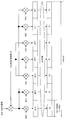
- Normal PUCCH format (see, for example, FIG. 3) is applied to all four subframes as shown in FIG. As shown in FIG. 12, in Normal PUCCH format, the response signal mapped to each slot is spread by a Walsh sequence (sequence length 4).
- the response signal mapped to the symbols excluding the final symbol is spread by DFT (sequence length 3).
- DFT sequence length 3
- no signal is mapped to the resource (SRS symbol) corresponding to the symbol (final SC-FDMA symbol) to which SRS is mapped.
- SRS symbol resource corresponding to the symbol (final SC-FDMA symbol) to which SRS is mapped.
- the first half slot of the subframe in which this transmission format is set it corresponds to a resource (that is, the last SC-FDMA symbol of the second half slot) to which no signal is mapped in the latter half slot of the transmission format. No signal is mapped even in the resource (that is, the last SC-FDMA symbol in the first half slot).
- the PUCCH format applied to all subframes in the X subframe interval is switched depending on whether or not an SRS transmission candidate subframe exists in the X subframe interval.
- a common PUCCH format is set in all subframes in the X subframe interval regardless of whether or not an SRS transmission candidate subframe exists in the X subframe interval.
- the base station 100 can in-phase combine the signal before despreading with respect to the received PUCCH signal.
- a symbol to which the SRS is mapped in the SRS transmission candidate subframe (last SC-FDMA symbol in the second half slot) No signal is mapped in the resource corresponding to (SRS symbol). Therefore, even when an SRS transmission candidate subframe exists in the X subframe section, collision between the response signal and the SRS can be avoided.
- the base station 100 when an SRS transmission candidate subframe exists in the X subframe section, the same transmission format is set in all slots in the X subframe section. Thereby, the base station 100 can synthesize not only the latter half slots but also the signals of both the former half slot and the latter half slot. Therefore, in this embodiment, when there are SRS transmission candidate subframes in the X subframe section, multiple subframe channel estimation and symbol level synthesis using 2X slots (8 slots in FIG. 12) are performed. Can do. As described above, according to the present embodiment, the channel estimation accuracy can be further improved.
- Embodiment 3 In Embodiment 1 and Embodiment 2, when even one SRS transmission candidate subframe exists in the X subframe section, the last SC-FDMA symbol (for example, FIG. 11) in all subframes of the X subframe. Or the seventh SC-FDMA symbol and the last SC-FDMA symbol (that is, the last SC-FDMA symbol of each slot, see FIG. 12, for example), so that the overhead is increased. .
- the base station and the terminal according to the present embodiment have the same basic configuration as the base station 100 and the terminal 200 according to the first embodiment, description will be made with reference to FIG. 9 and FIG.
- the base station 100 notifies the terminal 200 of srs-SubframeConfig as a cell-specific upper layer notification for setting an SRS resource candidate group.
- Base station 100 notifies terminal 200 in advance of the number of repetitions (N Rep ) before PUCCH transmission / reception.
- the repetition count (N Rep ) may be notified from the base station 100 to the terminal 200 via a terminal-specific upper layer, or may be notified using the PDCCH for MTC.
- the base station 100 notifies the terminal 200 of the value of the parameter X in advance before the transmission / reception of the PUCCH.
- the terminal 200 transmits the PUCCH by repetition for the number of repetitions (N Rep ) notified from the base station 100.
- N Rep the number of repetitions
- terminal 200 transmits a repetition signal continuously in X subframes using the same resource in at least consecutive X subframes.
- terminal 200 determines whether or not an SRS transmission candidate subframe exists in each of the X subframe sections based on srs-SubframeConfig notified from base station 100.
- the terminal 200 sets Normal PUCCH format in all the X subframes. Also, when an SRS transmission candidate subframe is included in the X subframe, terminal 200 sets Normal PUCCH format in all the X subframes.
- base station 100 sets NormalCPUCCH format in all X subframes regardless of whether or not an SRS transmission candidate subframe is included in the X subframe to be repeated in terminal 200.
- base station 100 uses the symbol to which the SRS is mapped and the symbol in the SRS transmission candidate subframe. In-phase synthesis is performed except for symbols corresponding to a pair of codes in a partially orthogonal relationship with corresponding codes.
- Normal PUCCH format is set in all four subframes as shown in FIG. .
- Walsh sequences orthogonal code sequences
- the orthogonal code sequence (1, 1, 1, 1) is partially orthogonal to each of the orthogonal code sequences (1, -1, 1, -1) and (1, -1, -1, 1).
- orthogonal code sequences that are partially orthogonal to each other among the four symbols corresponding to the sequence length, a sequence of the first two symbols (a sequence consisting of the two codes in the first half) is orthogonal, and a sequence of the second half subframe (second half 2).
- a sequence of two codes is also orthogonal.
- the base station 100 can separate a plurality of response signals code-multiplexed by orthogonal code sequences that are partially orthogonal in each subframe into two symbols in the first half and two symbols in the second half. Therefore, base station 100 can perform in-phase combining using the first two symbols in the SRS transmission candidate subframe included in the X subframe.
- Normal PUCCH format is used in all subframes.
- terminal 200 punctures and transmits the last SC-FDMA symbol and the previous SC-FDMA symbol, and partially orthogonally transmits an orthogonal code sequence used for response signal spreading. To two orthogonal code sequences.
- Embodiment 4 In Embodiments 1 to 3, it is assumed that received signals over a plurality of subframes (X subframes) can be combined in the same phase at the base station, and in repetition transmission, the phase of the transmitted signal is at least in the X subframe interval. It is assumed that there will be no continuity. In repetition transmission, there is also a consideration that phase discontinuity of a transmission signal does not occur unless transmission power and a center frequency of RF (Radio Frequency) are changed (see, for example, Non-Patent Document 10).
- RF Radio Frequency
- Embodiments 1 and 2 when even one SRS transmission candidate subframe exists in the X subframe section, the same transmission format as Shortened PUCCH format is used, so that every subframe or every slot Symbols for which data is not transmitted are generated (see, for example, FIGS. 11 and 12). In this case, a change in transmission power occurs every subframe or every slot. For this reason, the above-described condition that the phase discontinuity of the transmission signal does not occur is not satisfied, and the phase discontinuity may occur in the repetition transmission signal. As described above, when phase discontinuity of the transmission signal occurs, it is assumed that the in-phase synthesis of the reception signal over the X subframe cannot be performed in the base station, and as a result, the effect of improving the channel estimation accuracy cannot be sufficiently obtained.
- the base station and the terminal according to the present embodiment have the same basic configuration as the base station 100 and the terminal 200 according to the first embodiment, description will be made with reference to FIG. 9 and FIG.
- terminal 200 transmits data other than SRS resources (the final SC-FDMA symbol of the SRS transmission candidate subframe).
- a dummy symbol is inserted into a symbol that is not used. That is, when there is at least one SRS transmission candidate subframe in the X subframe interval, terminal 200 is a dummy resource that does not map signals in subframes other than the SRS transmission candidate subframe among the X subframes. Insert a symbol.
- FIG. 14 shows an example of dummy symbol insertion when Shorted PUCCH format is set in all subframes and PUCCH is transmitted by repetition in the same manner as in the first embodiment (FIG. 11).
- terminal 200 inserts a dummy symbol into a symbol having no transmission signal (final SC-FDMA symbol of each subframe) in a subframe other than the SRS transmission candidate subframe in FIG.
- FIG. 15 is similar to Embodiment 2 (FIG. 12), and applies the same transmission format as the second half slot of the Shorted PUCCH format in both the first half slot and the second half slot in all subframes. Shows an example of dummy symbol insertion in the case of repetition transmission. As shown in FIG. 15, terminal 200 inserts dummy symbols into symbols (no transmission signal) other than SRS resource candidates (SRS symbols) in FIG. 12 where data transmission is not performed.
- SRS symbols SRS resource candidates
- dummy symbols are inserted into symbols that are not transmitted with data generated by a transmission format for avoiding collision with SRS in PUCCH repetition.
- the method of switching the transmission format according to whether or not the SRS transmission candidate subframe exists in the X subframe period in the PUCCH repetition has been described. It can also be applied to the competition.
- the terminal 200 uses the normal PUSCH format (maps data to 12SC-FDMA symbols) and continues with X subframes. To send PUCCH as a repetition.
- terminal 200 maps data to 11SC-FDMA symbols (symbols other than the final symbol) in all X subframes. And send PUSCH as a repetition. By doing so, the operation is made common between PUCCH and PUSCH, so that the system can be simplified.
- the transmission format is switched depending on whether or not an SRS transmission candidate subframe exists within the X subframe period of PUCCH repetition, and symbols other than the SRS symbols of the SRS transmission candidate subframe are used.
- the method of inserting a dummy symbol into a symbol for which data transmission is not performed can also be used for PUSCH repetition.
- the terminal 200 uses the normal PUSCH format (maps data to 12SC-FDMA symbols) and continues with X subframes. Then send PUSCH as a repetition.
- terminal 200 maps data to 11SC-FDMA symbols (symbols other than the final symbol) in all X subframes. And send PUSCH as a repetition. Also, dummy symbols are inserted into symbols in which data is not mapped in subframes other than the SRS transmission candidate subframe in the X subframe. By doing so, the operation is made common between PUCCH and PUSCH, so that the system can be simplified.
- FIGS. 11 to 15 show the case where the last subframe in the X subframe section is an SRS transmission candidate subframe.
- the present invention is not limited to this, and any subframe in the X subframe section is an SRS. Even in the case of a transmission candidate subframe, the above operation can be applied.
- repetition count, the value of parameter X, and the value of the parameter defined by srs-SubframeConfig used in the above embodiment are merely examples, and are not limited to these.
- each functional block used in the description of the above embodiment is typically realized as an LSI which is an integrated circuit.
- the integrated circuit may control each functional block used in the description of the above embodiment, and may include an input and an output. These may be individually made into one chip, or may be made into one chip so as to include a part or all of them.
- the name used here is LSI, but it may also be called IC, system LSI, super LSI, or ultra LSI depending on the degree of integration.
- the method of circuit integration is not limited to LSI, and implementation with a dedicated circuit or a general-purpose processor is also possible.
- An FPGA Field Programmable Gate Array
- a reconfigurable processor that can reconfigure the connection and setting of circuit cells inside the LSI may be used.
- a terminal uses a repetition unit that repeats an uplink signal over a plurality of subframes to generate a repetition signal, and uses the plurality of subframes to measure uplink reception quality.
- a transmission candidate subframe of a sounding reference signal (SRS) to be transmitted is not included, a first transmission format is set in all of the plurality of subframes, and the transmission candidate subframe is included in the plurality of subframes.
- a configuration is provided that includes a control unit that sets a second transmission format in all of the plurality of subframes, and a transmission unit that transmits the repetition signal in the set transmission format.
- no signal is mapped to the resource corresponding to the symbol to which the SRS is mapped in the transmission candidate subframe.
- each subframe includes a first slot and a second slot
- the SRS is mapped to the second slot of the transmission candidate subframe
- the second transmission format is set.
- no signal is mapped to the resource corresponding to the symbol to which the SRS is mapped.
- no signal is mapped to the resource corresponding to the resource to which the signal is not mapped in the second half slot of the second transmission format.
- the repetition signal is spread using any of a plurality of orthogonal code sequences that are partially orthogonal to each other
- the control unit includes the transmission candidate subframes included in the plurality of subframes, The first symbol to which the SRS is mapped and the second code corresponding to the second code paired in a partially orthogonal relationship with the first code corresponding to the first symbol among the plurality of codes constituting the orthogonal code sequence. Puncture two symbols.
- control unit adds a dummy symbol to a resource to which the signal is not transmitted in a subframe other than the transmission candidate subframe among the plurality of subframes in which the second transmission format is set. insert.
- the first transmission format is Normal PUCCH format and the second transmission format is ShortenedtenPUCCH format.
- the base station when a transmission candidate subframe of a sounding reference signal (SRS) used for measurement of uplink reception quality is not included in a plurality of subframes in which an uplink signal is repeated,
- SRS sounding reference signal
- a first transmission format is set for all of the plurality of subframes
- the transmission candidate subframe is included in the plurality of subframes
- a second transmission format is set for all of the plurality of subframes. It adopts a configuration comprising a control unit for setting and a receiving unit for receiving the repetition signal in the set transmission format.
- an uplink signal is repeated over a plurality of subframes to generate a repetition signal, and a sounding reference used for measuring uplink reception quality is included in the plurality of subframes.
- a transmission candidate subframe of a signal SRS
- a first transmission format is set for all of the plurality of subframes, and the transmission candidate subframe is included in the plurality of subframes
- a second transmission format is set in all of the plurality of subframes, and the repetition signal is transmitted in the set transmission format.
- a transmission candidate subframe of a sounding reference signal (SRS) used for measurement of uplink reception quality is not included in a plurality of subframes in which an uplink signal is repeated
- SRS sounding reference signal
- One embodiment of the present disclosure is useful for a mobile communication system.
Landscapes
- Engineering & Computer Science (AREA)
- Signal Processing (AREA)
- Computer Networks & Wireless Communication (AREA)
- Power Engineering (AREA)
- Mobile Radio Communication Systems (AREA)
- Detection And Prevention Of Errors In Transmission (AREA)
Abstract
L'invention concerne une unité de répétition de la présente invention qui génère un signal de répétition par la répétition d'un signal de liaison montante à travers une pluralité de sous-trames, une unité de commande de ce dernier établit un premier format d'émission pour toutes les sous-trames, lorsqu'une sous-trame candidate d'émission pour un signal de référence de sondage (SRS) devant être utilisée dans la mesure de qualité de réception de liaison montante n'est pas comprise dans la pluralité de sous-trames, et établit un second format d'émission pour toutes les sous-trames, lorsque la sous-trame candidate d'émission est contenue dans la pluralité de sous-trames, et une unité d'émission de cette dernière émet le signal de répétition à l'aide du format d'émission établi.
Priority Applications (7)
| Application Number | Priority Date | Filing Date | Title |
|---|---|---|---|
| CN202111346222.5A CN114221742B (zh) | 2015-07-28 | 2016-03-09 | 通信装置、通信方法及集成电路 |
| EP16829976.6A EP3331298B1 (fr) | 2015-07-28 | 2016-03-09 | Dispositif et procédé correspondant de transmission de signaux de type srs |
| CN201680003947.5A CN107006010B (zh) | 2015-07-28 | 2016-03-09 | 基站、终端、接收方法及发送方法 |
| JP2017530983A JP6714593B2 (ja) | 2015-07-28 | 2016-03-09 | 端末および通信方法 |
| US15/653,154 US10455390B2 (en) | 2015-07-28 | 2017-07-18 | Terminal and transmission method for transmitting repetition signals using a transmission format that accommodates SRS transmission |
| US16/570,457 US11082112B2 (en) | 2015-07-28 | 2019-09-13 | Base station and reception method for receiving repetition signals using a channel format that accommodates SRS transmission |
| US17/354,637 US11910288B2 (en) | 2015-07-28 | 2021-06-22 | Integrated circuit for transmitting a PUCCH repetition signal using a channel format that accommodates SRS transmission |
Applications Claiming Priority (2)
| Application Number | Priority Date | Filing Date | Title |
|---|---|---|---|
| JP2015148545 | 2015-07-28 | ||
| JP2015-148545 | 2015-07-28 |
Related Child Applications (1)
| Application Number | Title | Priority Date | Filing Date |
|---|---|---|---|
| US15/653,154 Continuation US10455390B2 (en) | 2015-07-28 | 2017-07-18 | Terminal and transmission method for transmitting repetition signals using a transmission format that accommodates SRS transmission |
Publications (1)
| Publication Number | Publication Date |
|---|---|
| WO2017017866A1 true WO2017017866A1 (fr) | 2017-02-02 |
Family
ID=57885119
Family Applications (1)
| Application Number | Title | Priority Date | Filing Date |
|---|---|---|---|
| PCT/JP2016/001293 Ceased WO2017017866A1 (fr) | 2015-07-28 | 2016-03-09 | Station de base, terminal, procédé de réception et procédé d'émission |
Country Status (5)
| Country | Link |
|---|---|
| US (3) | US10455390B2 (fr) |
| EP (1) | EP3331298B1 (fr) |
| JP (3) | JP6714593B2 (fr) |
| CN (2) | CN114221742B (fr) |
| WO (1) | WO2017017866A1 (fr) |
Families Citing this family (7)
| Publication number | Priority date | Publication date | Assignee | Title |
|---|---|---|---|---|
| EP4287547A3 (fr) * | 2016-02-05 | 2024-01-03 | Sony Group Corporation | Dispositifs de communication, équipement d'infrastructure et procédés |
| RU2719359C2 (ru) | 2016-02-05 | 2020-04-17 | Панасоник Интеллекчуал Проперти Корпорэйшн оф Америка | Терминал и способ передачи |
| EP3678313A4 (fr) * | 2017-09-01 | 2021-03-17 | NTT DoCoMo, Inc. | Appareil et procédé de communication |
| US11303399B2 (en) * | 2018-05-11 | 2022-04-12 | At&T Intellectual Property I, L.P. | Reference signal transmission scheme for non-orthogonal multiple access systems |
| WO2020066232A1 (fr) * | 2018-09-27 | 2020-04-02 | パナソニック インテレクチュアル プロパティ コーポレーション オブ アメリカ | Terminal, et procédé de réception |
| US11503609B2 (en) * | 2019-09-27 | 2022-11-15 | Qualcomm Incorporated | PUCCH repetition before RRC connection setup |
| JP7792649B2 (ja) * | 2021-04-26 | 2025-12-26 | 国立大学法人愛媛大学 | 化合物、蛍光色素剤、キット及び細胞の検出方法 |
Citations (1)
| Publication number | Priority date | Publication date | Assignee | Title |
|---|---|---|---|---|
| JP2013528016A (ja) * | 2010-04-02 | 2013-07-04 | インターデイジタル パテント ホールディングス インコーポレイテッド | アップリンクサウンディング基準信号の構成および送信 |
Family Cites Families (23)
| Publication number | Priority date | Publication date | Assignee | Title |
|---|---|---|---|---|
| CN101617489B (zh) * | 2007-03-29 | 2013-11-06 | Lg电子株式会社 | 在无线通信系统中发送探测参考信号的方法 |
| US8009721B2 (en) * | 2007-06-15 | 2011-08-30 | Panasonic Corporation | Wireless communication apparatus and response signal spreading method |
| WO2010016273A1 (fr) * | 2008-08-08 | 2010-02-11 | パナソニック株式会社 | Station de base et terminal |
| CN102123479B (zh) * | 2010-01-08 | 2015-09-16 | 索尼公司 | 支持载波汇聚的通信系统及其系统信息更新方法和设备 |
| KR101781854B1 (ko) * | 2010-02-04 | 2017-09-26 | 엘지전자 주식회사 | 사운딩 참조 신호를 전송하는 방법 및 장치 |
| KR101328213B1 (ko) * | 2010-02-12 | 2013-11-14 | 엘지전자 주식회사 | 무선 통신 시스템에서 데이터 전송 방법 및 장치 |
| WO2011105857A2 (fr) * | 2010-02-25 | 2011-09-01 | Lg Electronics Inc. | Procédé et appareil de transmission d'informations de commande dans un système de communication sans fil |
| US8737333B2 (en) * | 2010-11-08 | 2014-05-27 | Acer Incorporated | Method of power reporting and communication device thereof |
| WO2012081812A1 (fr) * | 2010-12-16 | 2012-06-21 | 엘지전자 주식회사 | Procédé et dispositif permettant à un noeud relais de transmettre un signal de référence de sondage à une station de base dans un système de communication sans fil |
| CN102098086B (zh) * | 2010-12-30 | 2016-03-02 | 中兴通讯股份有限公司 | 数据发送方法及装置 |
| WO2013005377A1 (fr) * | 2011-07-01 | 2013-01-10 | パナソニック株式会社 | Appareil récepteur, appareil émetteur, procédé de réglage et procédé de détermination |
| CN103037492B (zh) * | 2011-10-09 | 2016-06-29 | 华为技术有限公司 | 上行发送功率确定方法及用户设备 |
| JP5400905B2 (ja) * | 2012-01-18 | 2014-01-29 | シャープ株式会社 | 無線通信システム |
| JP2013236288A (ja) * | 2012-05-10 | 2013-11-21 | Sharp Corp | 端末、通信方法および集積回路 |
| KR101475123B1 (ko) * | 2012-09-14 | 2014-12-22 | 주식회사 케이티 | 상향링크 제어채널 전송방법 및 수신방법, 그 단말, 그 송수신포인트 |
| CN109327822B (zh) * | 2012-10-05 | 2022-10-25 | 交互数字专利控股公司 | 增强机器类型通信(mtc)设备覆盖的方法和装置 |
| US9596065B2 (en) * | 2012-10-24 | 2017-03-14 | Qualcomm Incorporated | Enhanced SRS transmission for MIMO operation in LTE-A |
| WO2014109569A1 (fr) * | 2013-01-09 | 2014-07-17 | 엘지전자 주식회사 | Procédé de transmission de signal et appareil associé |
| RU2627739C1 (ru) * | 2013-09-11 | 2017-08-11 | Хуавей Текнолоджиз Ко., Лтд. | Способ конфигурации опорного сигнала информации о состоянии канала и базовая станция |
| JP5576975B2 (ja) * | 2013-10-24 | 2014-08-20 | シャープ株式会社 | 移動局装置、通信方法および集積回路 |
| CN104639271B (zh) * | 2013-11-15 | 2017-04-26 | 华为技术有限公司 | 一种下行sinr估算方法和基站 |
| US10516517B2 (en) * | 2015-01-29 | 2019-12-24 | Intel IP Corporation | System and methods for support of frequency hopping for UEs with reduced bandwidth support |
| EP3749039B1 (fr) * | 2015-09-25 | 2024-01-03 | Huawei Technologies Co., Ltd. | Procédé de transmission montante d'informations, station de base et équipement utilisateur |
-
2016
- 2016-03-09 WO PCT/JP2016/001293 patent/WO2017017866A1/fr not_active Ceased
- 2016-03-09 JP JP2017530983A patent/JP6714593B2/ja active Active
- 2016-03-09 CN CN202111346222.5A patent/CN114221742B/zh active Active
- 2016-03-09 CN CN201680003947.5A patent/CN107006010B/zh active Active
- 2016-03-09 EP EP16829976.6A patent/EP3331298B1/fr active Active
-
2017
- 2017-07-18 US US15/653,154 patent/US10455390B2/en active Active
-
2019
- 2019-09-13 US US16/570,457 patent/US11082112B2/en active Active
-
2020
- 2020-06-04 JP JP2020097788A patent/JP7035114B2/ja active Active
-
2021
- 2021-06-22 US US17/354,637 patent/US11910288B2/en active Active
-
2022
- 2022-03-02 JP JP2022031863A patent/JP7224506B2/ja active Active
Patent Citations (1)
| Publication number | Priority date | Publication date | Assignee | Title |
|---|---|---|---|---|
| JP2013528016A (ja) * | 2010-04-02 | 2013-07-04 | インターデイジタル パテント ホールディングス インコーポレイテッド | アップリンクサウンディング基準信号の構成および送信 |
Non-Patent Citations (2)
| Title |
|---|
| LG ELECTRONICS: "Details on SR repetition and SRS transmission for MTC UE", 3GPP TSG- RAN WG1#81 RL-152705, 16 May 2015 (2015-05-16), XP050973724, Retrieved from the Internet <URL:http://www.3gpp. org/ftp/tsg_ran/WG1_RL1/TSGR1_81/Docs/R1-152705. zip> [retrieved on 20160415] * |
| PANASONIC: "Handling of collisions between MTC channels and legacy SRS", 3GPP TSG-RAN WG1#82 RL-153968, 14 August 2015 (2015-08-14), XP050991660, Retrieved from the Internet <URL:http://www.3gpp.org/ ftp/tsg_ran/WG1_RL1/TSGR1_82/Docs/R1-153968. zip> [retrieved on 20160415] * |
Also Published As
| Publication number | Publication date |
|---|---|
| US10455390B2 (en) | 2019-10-22 |
| US20170318411A1 (en) | 2017-11-02 |
| CN114221742B (zh) | 2024-03-08 |
| JP6714593B2 (ja) | 2020-06-24 |
| JP2022078182A (ja) | 2022-05-24 |
| US11910288B2 (en) | 2024-02-20 |
| CN114221742A (zh) | 2022-03-22 |
| EP3331298A4 (fr) | 2018-08-01 |
| JP2020150559A (ja) | 2020-09-17 |
| US20210320696A1 (en) | 2021-10-14 |
| CN107006010B (zh) | 2021-11-05 |
| US20200008032A1 (en) | 2020-01-02 |
| US11082112B2 (en) | 2021-08-03 |
| JP7224506B2 (ja) | 2023-02-17 |
| EP3331298B1 (fr) | 2020-09-09 |
| JPWO2017017866A1 (ja) | 2018-05-10 |
| JP7035114B2 (ja) | 2022-03-14 |
| CN107006010A (zh) | 2017-08-01 |
| EP3331298A1 (fr) | 2018-06-06 |
Similar Documents
| Publication | Publication Date | Title |
|---|---|---|
| US12107622B2 (en) | Terminal and transmission method | |
| JP7224506B2 (ja) | 通信装置、通信方法および集積回路 | |
| WO2017017865A1 (fr) | Terminal, station de base, procédé d'émission et procédé de réception | |
| JP6845951B2 (ja) | 基地局、受信方法及び集積回路 |
Legal Events
| Date | Code | Title | Description |
|---|---|---|---|
| 121 | Ep: the epo has been informed by wipo that ep was designated in this application |
Ref document number: 16829976 Country of ref document: EP Kind code of ref document: A1 |
|
| ENP | Entry into the national phase |
Ref document number: 2017530983 Country of ref document: JP Kind code of ref document: A |
|
| REEP | Request for entry into the european phase |
Ref document number: 2016829976 Country of ref document: EP |
|
| NENP | Non-entry into the national phase |
Ref country code: DE |