WO2017017890A1 - Terminal sans fil, station de base et procédé correspondant - Google Patents
Terminal sans fil, station de base et procédé correspondant Download PDFInfo
- Publication number
- WO2017017890A1 WO2017017890A1 PCT/JP2016/002976 JP2016002976W WO2017017890A1 WO 2017017890 A1 WO2017017890 A1 WO 2017017890A1 JP 2016002976 W JP2016002976 W JP 2016002976W WO 2017017890 A1 WO2017017890 A1 WO 2017017890A1
- Authority
- WO
- WIPO (PCT)
- Prior art keywords
- access
- category
- layer
- burring
- broadcast
- Prior art date
- Legal status (The legal status is an assumption and is not a legal conclusion. Google has not performed a legal analysis and makes no representation as to the accuracy of the status listed.)
- Ceased
Links
Images



Classifications
-
- H—ELECTRICITY
- H04—ELECTRIC COMMUNICATION TECHNIQUE
- H04W—WIRELESS COMMUNICATION NETWORKS
- H04W48/00—Access restriction; Network selection; Access point selection
- H04W48/02—Access restriction performed under specific conditions
-
- H—ELECTRICITY
- H04—ELECTRIC COMMUNICATION TECHNIQUE
- H04W—WIRELESS COMMUNICATION NETWORKS
- H04W48/00—Access restriction; Network selection; Access point selection
- H04W48/08—Access restriction or access information delivery, e.g. discovery data delivery
- H04W48/10—Access restriction or access information delivery, e.g. discovery data delivery using broadcasted information
-
- H—ELECTRICITY
- H04—ELECTRIC COMMUNICATION TECHNIQUE
- H04W—WIRELESS COMMUNICATION NETWORKS
- H04W4/00—Services specially adapted for wireless communication networks; Facilities therefor
- H04W4/06—Selective distribution of broadcast services, e.g. multimedia broadcast multicast service [MBMS]; Services to user groups; One-way selective calling services
-
- H—ELECTRICITY
- H04—ELECTRIC COMMUNICATION TECHNIQUE
- H04W—WIRELESS COMMUNICATION NETWORKS
- H04W4/00—Services specially adapted for wireless communication networks; Facilities therefor
- H04W4/50—Service provisioning or reconfiguring
-
- H—ELECTRICITY
- H04—ELECTRIC COMMUNICATION TECHNIQUE
- H04W—WIRELESS COMMUNICATION NETWORKS
- H04W76/00—Connection management
- H04W76/10—Connection setup
- H04W76/18—Management of setup rejection or failure
-
- H—ELECTRICITY
- H04—ELECTRIC COMMUNICATION TECHNIQUE
- H04W—WIRELESS COMMUNICATION NETWORKS
- H04W88/00—Devices specially adapted for wireless communication networks, e.g. terminals, base stations or access point devices
- H04W88/02—Terminal devices
-
- H—ELECTRICITY
- H04—ELECTRIC COMMUNICATION TECHNIQUE
- H04W—WIRELESS COMMUNICATION NETWORKS
- H04W88/00—Devices specially adapted for wireless communication networks, e.g. terminals, base stations or access point devices
- H04W88/08—Access point devices
- H04W88/10—Access point devices adapted for operation in multiple networks, e.g. multi-mode access points
-
- H—ELECTRICITY
- H04—ELECTRIC COMMUNICATION TECHNIQUE
- H04W—WIRELESS COMMUNICATION NETWORKS
- H04W48/00—Access restriction; Network selection; Access point selection
- H04W48/08—Access restriction or access information delivery, e.g. discovery data delivery
- H04W48/12—Access restriction or access information delivery, e.g. discovery data delivery using downlink control channel
-
- H—ELECTRICITY
- H04—ELECTRIC COMMUNICATION TECHNIQUE
- H04W—WIRELESS COMMUNICATION NETWORKS
- H04W48/00—Access restriction; Network selection; Access point selection
- H04W48/16—Discovering, processing access restriction or access information
-
- H—ELECTRICITY
- H04—ELECTRIC COMMUNICATION TECHNIQUE
- H04W—WIRELESS COMMUNICATION NETWORKS
- H04W84/00—Network topologies
- H04W84/02—Hierarchically pre-organised networks, e.g. paging networks, cellular networks, WLAN [Wireless Local Area Network] or WLL [Wireless Local Loop]
- H04W84/04—Large scale networks; Deep hierarchical networks
- H04W84/042—Public Land Mobile systems, e.g. cellular systems
- H04W84/045—Public Land Mobile systems, e.g. cellular systems using private Base Stations, e.g. femto Base Stations, home Node B
Definitions
- the present disclosure relates to a wireless communication network, and more particularly to barring of access by a wireless terminal.
- Non-Patent Document 1 describes Application-specific Congestion control for Data Communication (ACDC).
- ACDC is an access that allows an operator to allow or prevent new access attempts (access attempts) from applications specified by the operator in a wireless terminal (User Equipment (UE)) in idle mode. Control mechanism.
- UE User Equipment
- the use of ACDC allows an operator to prevent or mitigate overload of either or both of the access network and the core network.
- ACDC is applied only when the UE is in idle mode (e.g., RRC_IDLE) and not when the UE is in connected mode (e.g., RRC_CONNECTED).
- a home network i.e., Home Public Land Mobile Mobile Network (HPLMN) or Equivalent HPLMN
- HPLMN Home Public Land Mobile Mobile Network
- Equivalent HPLMN can configure at least four ACDC categories in the UE.
- Each ACDC category is associated with an application, application group, or service specified by the operator.
- provisioning to UEs in the ACDC category is the responsibility of the home network and is outside the scope of the 3rd Generation Generation Partnership Project (3GPP).
- An operator of the home network may set the ACDC category in, for example, the Universal Subscriber Identity Module (USIM).
- USIM Universal Subscriber Identity Module
- the operator of the home network may set the ACDC setting to the UE according to Open Mobile Alliance Device Management (OMA-DM).
- OMA-DM Open Mobile Alliance Device Management
- the serving network ie, HPLMN, EquivalentNHPLMN, or VisitedVPPLMN (VPLMN)
- HPLMN EquivalentNHPLMN
- VPLMN VisitedVPPLMN
- the serving network provides barring information for each ACDC category and control information indicating whether ACDC is imposed on the roaming UE. Broadcast within the RAN area.
- the UE determines whether access attempts for an application (access attempt) are allowed, the burring information broadcast by the serving network, and the setting of the ACDC category in the UE (ie, between the ACDC category and the application). Control based on mapping.
- the home network is implemented as follows. Applications whose use is expected to be subject to minimal restrictions are assigned the highest ACDC category (the highest rank). The applications that are expected to be restricted in use than the applications to which the highest ACDC category is assigned are the second highest ACDC category (the second-highest ACDC category) (second highest) Rank). The same applies when assigning applications to the third and higher ACDC categories. The applications whose use is expected to be most restricted are either assigned the lowest ACDC category (the lowest rank) (lowest rank) or not categorized at all.
- An application on a UE that is not assigned any ACDC category is handled by the UE as part of the lowest ACDC category configured in the UE. If the operator needs to distinguish between these uncategorized applications, the operator should avoid assigning the application to the lowest ACDC category.
- the serving network broadcasts burring information from the highest ACDC category to the lowest ACDC category.
- the home network and the serving network may use different categorizations. That is, the number of ACDC categories (the number of ACDC categories) set on the UE by the operator of the home network may not be the same as the number of ACDC categories broadcast by the serving network (the number of ACDCg categories). This can occur, for example, when the UE is roaming and the number of ACDC categories broadcast by the serving network is different from that of the home network. In such a case, the UE operates as follows.
- the UE uses burring information for matching ACDC categories and serves uncategorized applications. Stop by barring information for the lowest (ACDC) category broadcast by the network (bar) and ignore barring information for unmatched ACDC categories (ignore).
- the UE uses the burring information for matching ACDC categories, Block other applications (including those belonging to the unmatched ACDC category) with the burring information for the lowest (ACDC) category broadcast by the serving network (bar).
- the matching ACDC category is an ACDC category in which burring information is broadcast by the serving network and has the same rank as the ACDC category rank set for the UE.
- the unmatched ACDC category (a) the burring information is broadcast by the serving network, but the corresponding ACDC category is not set to the UE, or (b) the ACDC category is set to the UE. Is an ACDC category in which burring information corresponding to this is not broadcast from the serving network.
- Non-Patent Document 2 proposes which layer (application layer, Non-Access Stratum (NAS) layer, or Radio Resource Control (RRC) layer) should perform UE operations necessary for ACDC.
- NAS Non-Access Stratum
- RRC Radio Resource Control
- Non-Patent Document 2 introduces several options in which each of the application layer, the NAS layer, and the RRC layer performs an ACDC check.
- the ACDC check determines whether to allow an application-triggered access attempt (access attempt), the burring information broadcast from the serving network and the ACDC category to which the application belongs, determined based on the ACDC configuration in the UE And determining based on the above.
- NAS layer performs ACDC check, if the UE receives Evolved Packet System (EPS) connection management IDLE (ECM-IDLE) mode (or EPS Mobility management) in response to receiving a session establishment request from a higher layer.
- EMM-IDLE Evolved Packet System
- NAS layer if IDLE (EMM-IDLE) mode) 1. Determine the ID (OS App ID) of the application that triggered the request, 2. Determine which ACDC category the OS App ID belongs to based on information provisioned to the UE by the home network operator via OMA-DM or USIM, 3. Obtain burring information for the determined ACDC category from the RCC layer, 4). Perform ACDC check, 5). If the ACDC check is passed, the service request procedure is continued (proceed).
- EPS Evolved Packet System
- ECM-IDLE Evolved Packet System
- Non-Patent Document 2 proposes two options for the RRC layer to perform an ACDC check.
- One option for the RRC layer to perform an ACDC check is that if the UE is in the RRC_IDLE state in response to receiving an access attempt request, the RRC layer 1. Determine the ID (OS App ID) of the application that triggered the request, 2. Determine which ACDC category the OS App ID belongs to based on information provisioned to the UE by the home network operator via OMA-DM or USIM, 3. Perform ACDC check based on burring information for the determined ACDC category obtained from System Information Block (SIB) information, 4). If the ACDC check is passed, the access attempt is continued (proceed).
- SIB System Information Block
- the RRC layer performs an ACDC check
- the NAS layer if the UE is in ECM-IDLE mode (or EMM-IDLE mode), in response to receiving a session establishment request, 1. Determine the ID (OS App ID) of the application that triggered the request, 2. Determine which ACDC category the OS App ID belongs to based on information provisioned to the UE by the home network operator via Open Mobile Alliance Device Management (OMA-DM) or USIM, 3. The determined ACDC category is passed to the RRC layer together with Service Request and Call type. Next, the RRC layer has received a Service Request from the NAS layer along with the ACDC category and Call type, 1. Perform ACDC check based on burring information for the received ACDC category obtained from System Information Block (SIB) information, 2. If the ACDC check is passed, the access attempt is continued (proceed).
- SIB System Information Block
- Non-Patent Document 2 presents several options related to the interaction between the application layer, the NAS layer, and the RRC layer when the UE executes ACDC.
- the operation of the UE is not clear when the number of ACDC categories set for the UE (the number number of ACDC categories) is not the same as the number of ACDC categories broadcast by the serving network (the number number of ACDC categories).
- Non-Patent Document 1 indicates that if the serving network broadcasts fewer ACDC categories (categories) than the UE configuration (UE's configuration), the UE is for matching ACDC categories (categories). It describes using burring information and blocking other applications with burring information for the lowest (ACDC) category broadcast by the serving network. Therefore, when the application that triggers the access attempt belongs to the “unmatched ACDC category”, the UE can use the specific ACDC category (eg, lowest) that the application is broadcast by the serving network to perform the ACDC check for the application. ACDC category). However, the interaction of the application layer, NAS layer, and RRC layer for performing this operation by the UE is not clarified.
- the “unmatched ACDC category” means an ACDC category in which the ACDC category is set to UE, but the corresponding burring information is not broadcast from the serving network.
- the serving network broadcasts burring information corresponding to the access burring category (eg, ACDC category) to which the application that triggers the access attempt belongs. It is to provide an apparatus, a method, and a program that contribute to providing an operation in a wireless terminal to cope with a case where it is not. It should be noted that this object is only one of a plurality of objects that the embodiments disclosed herein intend to achieve. Other objects or problems and novel features will become apparent from the description of the present specification or the accompanying drawings.
- the access burring category eg, ACDC category
- a wireless terminal includes a wireless transceiver and at least one processor.
- the at least one processor is coupled to the radio transceiver and is configured to operate as a non-access stratum (NAS) layer that provides mobility management and session management and an access stratum (AS) layer that provides radio resource control.
- NAS non-access stratum
- AS access stratum
- the NAS layer is adapted to obtain from the AS layer either or both of information of one or more access barring categories broadcast by a serving network and the number of the one or more access barring categories. (Adapted).
- the NAS layer further sets the first access barring category when burring information corresponding to the first access barring category to which an application that triggers session establishment belongs is not broadcast by the serving network.
- the NAS layer is further adapted to pass the specific access barring category along with a NAS message for session establishment to the AS layer.
- the AS layer is adapted to control whether to allow access attempts triggered by the NAS layer based on burring information corresponding to the specific access burring category broadcast by the serving network.
- the method in the wireless terminal is: (A) Non-access from information of one or more access barring categories and / or the number of the one or more access barring categories broadcasted by the serving network from the access stratum (AS) layer. sending to stratum (NAS) layer, (B) If the serving network does not broadcast burring information corresponding to the first access burring category to which the application that triggers session establishment belongs, the first access burring category is transmitted by the serving network. Replacing the NAS layer with a specific access barring category of the one or more access barring categories to be broadcast; (C) passing the specific access barring category along with a NAS message for session establishment from the NAS layer to the AS layer; and (d) the specific access barring category broadcast by the serving network. Controlling by the AS layer whether to allow access attempts triggered by the NAS layer based on burring information corresponding to including.
- the wireless terminal includes a wireless transceiver and at least one processor.
- the at least one processor is coupled to the radio transceiver and is configured to operate as a non-access stratum (NAS) layer that provides mobility management and session management and an access stratum (AS) layer that provides radio resource control.
- NAS non-access stratum
- AS access stratum
- the NAS layer is adapted to pass a first access barring category to which an application that triggers session establishment belongs to the AS layer together with a NAS message for session establishment.
- the AS layer has one or more access burrings reported by the serving network when burring information corresponding to the first access burring category received from the NAS layer is not broadcast by the serving network.
- the AS layer Adapted to select a particular access barring category of the categories as an alternative to the first access barring category;
- the AS layer further controls whether to allow an access attempt triggered by the NAS layer based on burring information corresponding to the specific access burring category broadcasted by the serving network. Be adapted.
- the method in the wireless terminal is: (A) passing the first access barring category to which the application that triggers session establishment belongs together with the NAS message for session establishment from the non-access stratum (NAS) layer to the access stratum (AS) layer; (B) one or more access burring categories broadcast by the serving network when burring information corresponding to the first access burring category received from the NAS layer is not broadcast by the serving network. Selecting a specific access barring category of the AS by the AS layer instead of the first access barring category, and (c) the specific access barring category broadcast by the serving network Controlling by the AS layer whether to allow access attempts triggered by the NAS layer based on burring information corresponding to including.
- a base station in a fifth aspect, includes a wireless transceiver configured to communicate with wireless terminals in a cell, and at least one processor coupled to the wireless transceiver.
- the at least one processor is configured to broadcast in the cell one or more access barring categories, burring information for each of the one or more access barring categories, and mapping rules.
- the mapping rule defines a mapping between the one or more access barring categories broadcast by the base station and one or more access barring categories provisioned to the wireless terminal.
- a method in a base station comprises broadcasting in a cell one or more access barring categories, burring information for each of the one or more access barring categories, and mapping rules. Including.
- the mapping rule defines a mapping between the one or more access barring categories broadcast by the base station and one or more access barring categories provisioned to the wireless terminal.
- the program includes a group of instructions (software code) for causing the computer to perform the method according to the second, fourth, or sixth aspect described above when read by the computer.
- the operation in the wireless terminal for coping with the case where the serving network does not broadcast burring information corresponding to the access burring category (eg, ACDC category) to which the application that triggers the access attempt belongs It is possible to provide an apparatus, a method, and a program that contribute to providing information.
- the access burring category eg, ACDC category
- EPS Evolved Packet System
- SAE System Architecture Evolution
- 3GPP UMTS 3GPP2 CDMA2000 systems (1xRTT, HRPD (High Rate Packet Data)
- GSM registered trademark
- GPRS General packet radio service
- WiMAX WiMAX
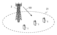
- FIG. 1 shows a configuration example of a wireless communication network according to some embodiments including this embodiment.
- the wireless communication network includes one or more wireless terminals (UE) 1 and a base station (eNB) 2.
- Each UE1 has at least one wireless transceiver and is configured to perform cellular communication with the eNB2.
- the eNB 2 is configured to manage the cell 21 and perform cellular communication with each of the plurality of UEs 1 using cellular communication technology (eg, Evolved Universal Terrestrial Radio Access (E-UTRA) technology).
- E-UTRA Evolved Universal Terrestrial Radio Access
- the eNB 2 shown in FIG. 1 may be a Baseband Unit (BBU) used in the Centralized Radio Access Network (C-RAN) architecture.
- BBU Baseband Unit
- C-RAN Centralized Radio Access Network
- the eNB 2 shown in FIG. 1 may be a RAN node connected to one or a plurality of Remote Radio Head (RRH).
- RRH Remote Radio Head
- the eNB 2 as a BBU is responsible for control plane processing and user plane digital baseband signal processing.
- RRH is in charge of analog radio frequency (RF) signal processing (e.g., frequency conversion and signal amplification).
- C-RAN is sometimes called Cloud RAN.
- a BBU may also be called Radio Equipment Controller (REC) or Data Unit (DU).
- RRH may also be called RadioRadEquipment (RE), Radio Unit (RU), or Remote Radio Unit (RRU).
- ENB 2 transmits access control information (e.g., burring information) corresponding to a predetermined access burring category (e.g., ACDC category).
- access control information e.g., burring information
- the eNB 2 broadcasts broadcast information (i.e., SIB information) 101 including ACDC control information related to access control by ACDC.
- the ACDC control information broadcast by the eNB 2 includes burring information for each ACDC category.
- Each UE1 controls whether to allow an access attempt to the eNB2 triggered by the application based on the burring information broadcast by the eNB2.
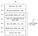
- FIG. 2 shows an example of the protocol stack of the control plane of UE1.
- the control plane protocol stack 200 of the UE 1 includes an application (APP) layer 201, a NAS layer 202, and an Access (Stratum (AS) 208 layer.
- the AS layer 208 includes an RRC layer 203, a Packet Data Convergence Protocol (PDCP) layer 204, a Radio Link Control (RLC) layer 205, a Medium Access Control (MAC) layer 206, and a physical (PHY) layer 207.
- PDCP Packet Data Convergence Protocol
- RLC Radio Link Control
- MAC Medium Access Control
- PHY physical
- the NAS layer 202 communicates with the core network (ie, Evolved Packet Core (EPC)) via the eNB 2 using data communication on the radio interface provided by the AS layer 208 and management of the radio interface.
- Mobility management ie, EPS EPS Mobility Management (EMM)
- EMM EPS EPS Session Management
- Mobility management (EMM) includes managing UE1's two NAS states for connection establishment with EPC: EMM state (EMM-DEREGISTERED or EMM-REGISTERD) and ECM state (ECM-IDLE or ECM-CONNECTED) .
- EMM state indicates whether UE1 is registered in Mobility Management Entity (MME) in EPC.
- MME Mobility Management Entity
- the ECM state represents the state of the NAS signaling connection between UE1 and EPC. Note that ECM-IDLE and ECM-CONNECTED may be referred to as EMM-IDLE and EMM-CONNECTED.
- the mobility management (EMM) protocol implemented in the NAS layer 202 includes an attach procedure, a detach procedure, and a Tracking Area Update (TAU) procedure.
- the mobility management (EMM) protocol further includes procedures for EMM connection management, that is, a service request procedure and a NAS message transfer procedure.
- Session management includes EPS bearer context management including activation, deactivation and modification of user plane bearer context (i.e., EPS bearer context). Session management (ESM) further includes requesting resources (IP connectivity to Packet ⁇ ⁇ Data ⁇ ⁇ ⁇ ⁇ Network (PDN) or dedicated bearer resources) by UE1.
- EPS bearer context management including activation, deactivation and modification of user plane bearer context (i.e., EPS bearer context).
- Session management (ESM) further includes requesting resources (IP connectivity to Packet ⁇ ⁇ Data ⁇ ⁇ ⁇ ⁇ Network (PDN) or dedicated bearer resources) by UE1.
- PDN Packet ⁇ ⁇ Data ⁇ ⁇ ⁇ ⁇ Network
- the NAS layer 202 communicates with the RRC layer 203 in order to use services provided by the AS layer 208 (data communication on the radio interface and management of the radio interface).
- the RRC layer 203 is a lower layer of the NAS layer 202, provides radio resource control (RRC), and manages the RRC state (RRC_IDLE or RRC_CONNECTED) of the UE1.
- RRC radio resource control
- the RRC state represents whether a radio connection (RRC connection) between UE1 and eNB2 is established.
- the NAS layer 202 in response to receiving a session establishment request from a higher layer (ie, application layer 201), the NAS layer 202 starts a service Request procedure if the UE is in the ECM-IDLE mode, Attempts to send a service request message to the MME.
- the service request message from the NAS layer 202 triggers the AS layer 208 to establish the RRC connection with the eNB 2, and the RRC layer 203 starts the RRC connection establishment procedure.
- UE1 performs the access trial to eNB2 triggered by the service request (Service
- the session is, for example, S1-MME, S1-U (S1 bearer), network bearer (E-RAB, EPS Bearer, S5 / S8 bearer), radio bearer (Radio Bearer), PDN connection, IP Connectivity Access Network Any or a combination of (IP-CAN) sessions are conceivable, but not limited thereto.
- Fig. 3 shows an example of ACDC control information (ACDC Information Element (IE)), which is assumed to be transmitted in System Information Blok Type 2 (SIB2).
- the eNB 2 may transmit information indicating whether ACDC is applied (or applying ACDC) to each (or a part) of the PLMN broadcast in the cell. Further, the eNB 2 may individually set and transmit these pieces of information (acdc-Category, acdc-BarringConfig) to each (or part of) the PLMN Identity broadcasted in the cell.
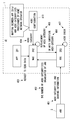
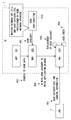
- FIG. 4 shows an example of ACDC operation by UE1.
- the eNB 2 transmits ACDC control information (ACDC IE) to the UE 1 (401).
- the ACDC control information includes one or more ACDC categories and burring information for each ACDC category.
- the eNB 2 includes ACDC control information in broadcast information (eg, SIB information) broadcast in the cell 21 so that at least the UE 1 in the idle mode (ECM-IDLE and RRC_IDLE) can receive the ACDC control information. Also good.
- the eNB 2 may transmit ACDC control information set in common to all (idle state) UEs 1 having an ACDC function in the cell, or set for each PLMNPLIdentity broadcasted in the cell.
- ACDC control information may be transmitted.
- the UE1 When the UE1 detects that the ACDC control information is transmitted for each PLMN Identity, the UE1 checks whether the PLMN Identity corresponding to the PLMN selected by the upper layer (NAS) of the UE1 is a target of ACDC. . When the PLMN Identity is subject to ACDC, UE1 performs access control by ACDC based on the ACDC control information set for the PLMN Identity.
- NAS upper layer
- the NAS layer 202 of UE1 RRCs one or more of the ACDC categories broadcast by the serving network (eNB2) and the number of these ACDC categories broadcast (the number of broadcasted ACDC category (ies)). Obtain (receive) from the layer 203 (402).
- the RRC layer 203 of UE1 is one of information on one or more ACDC categories broadcast by the serving network (eNB2) and the number of ACDC categories broadcast (the number of broadcasted ACDC category (ies)). Or both are notified to the NAS layer 202.
- the RRC layer 203 has more than one or more ACDC categories included in the ACDC configuration 410 in which the number of one or more ACDC categories broadcast by the serving network (eNB2) is provisioned to UE1. Or less, information on one or more ACDC categories broadcast by the serving network (eNB 2) and / or the number of these broadcast ACDC categories may be provided to the NAS layer 202. Thereby, the RRC layer 203 can provide the NAS layer 202 with the latest number of ACDC categories in the serving network.
- the RRC layer 203 receives the updated (that is, the latest) broadcast information (SIB information) broadcast by the serving network (eNB2), and the broadcast information is changed to ACDC control information.
- SIB information broadcast information
- One or more of the information of one or more ACDC categories broadcast by the serving network and the number of these broadcast ACDC categories may be provided to the NAS layer 202.
- the RRC layer 203 can provide the NAS layer 202 with the latest number of ACDC categories in the serving network.
- the RRC layer 203 may provide this to the NAS layer 202 only when the ACDC control information is updated, or when the broadcast information is updated regardless of whether the ACDC control information is updated.
- ACDC control information may be provided to the NAS layer 202.
- the RRC layer 203 may provide information on one or more ACDC categories broadcast by the serving network and these broadcast ACDCs when UE1 detects that ACDC is being applied in the serving network. Either or both of the number of categories may be provided to the NAS layer 202.
- the NAS layer 202 In response to receiving a data transmission request (in other words, session establishment request) 403 from the application layer 201, the NAS layer 202 triggers the request if UE1 is in the idle mode (eg, ECM-IDLE). Determine the application identifier of the selected application.
- the application identifier may include an OS App ID or an OS App ID.
- OS ID Operating System identifier
- OS ApppartID is used to identify a particular application.
- OS App ID is an OS-specific application identifier (application identifier).
- the NAS layer 202 determines, based on the ACDC configuration 410, which ACDC category the application that triggered the request belongs to (404).
- the ACDC configuration 410 is set in UE1 by UE1's home network operator and indicates a mapping between one or more applications (application identifiers) installed in UE1 and one or more ACDC categories.
- the ACDC configuration 410 may be set in the USIM implemented in the UE 1 by the home network operator.
- the home network operator may set the ACDC setting 410 to UE1 according to the OMA-DM.
- the serving network eNB2
- the ACDC category (first ACDC) to which the application that triggers the session establishment request belongs.
- the first ACDC category to which the application that triggers the session establishment request may be an unmatched ACDC category.
- the “unmatched ACDC category” here is an ACDC category in which the ACDC category is set to UE1, but the corresponding burring information is not broadcast from the serving network (eNB2).
- the NAS layer 202 is broadcast by the serving network when burring information corresponding to the first ACDC category (ie, the value of the first ACDC category) is not broadcast by the serving network (eNB2).
- a particular ACDC category of the one or more ACDC categories is selected in place of the first ACDC category (405).
- the NAS layer 202 replaces the first ACDC category (ie, the value of the first ACDC category) with the (substitute) specific ACDC category (ie, the value of the specific ACDC category) ( 405).
- the NAS layer 202 considers the application that triggers the session establishment request to belong to a particular ACDC category broadcast by the serving network instead of the first ACDC category (405).
- the serving network eNB2 broadcasts ACDC categories (categories) that are less than the ACDC configuration 410 provisioned to UE1, the NAS layer 202 is included in the ACDC configuration 410 of UE1.
- an ACDC category replacement is performed (405).
- the NAS layer 202 determines that the first ACDC category value is greater than the maximum value (ie, the lowest ACDC category value) of one or more ACDC categories that are broadcast by the serving network.
- the value of may be replaced by the value of a specific ACDC category. That is, the NAS layer 202 may use the value of a specific ACDC category (substitute) instead of the value of the first ACDC category.
- the NAS layer 202 identifies the value of the first ACDC category when the value of the ACDC category (and its burring information) corresponding to the value of the first ACDC category is not broadcast by the serving network. May be replaced by the value of the ACDC category. That is, the NAS layer 202 may use the value of a specific ACDC category (substitute) instead of the value of the first ACDC category.
- the particular ACDC category (alternative ACDC category) selected by the NAS layer 202 may be the lowest ACDC category of one or more ACDC categories broadcast by the serving network (eNB2). . Such replacement of the ACDC category may be preferable because it follows the handling of the unmatched ACDC category described in Non-Patent Document 1.
- the specific ACDC category (alternative ACDC category) selected by the NAS layer 202 may not be the lowest ACDC category in the serving network (eNB2).
- the NAS layer 202 follows a predetermined mapping rule.
- the particular ACDC category (substitute ACDC category) to be replaced by the first ACDC category may be determined.
- the mapping rule defines a mapping between a plurality of (possibly) ACDC categories broadcast by the serving network and one or more ACDC categories provisioned to UE1.
- the said mapping rule may be provisioned by UE1 and may be sent to UE1 from a serving network (eNB2).
- the NAS layer 202 sends the specific ACDC category (substitute ACDC category) selected as a substitute for the first ACDC category together with the NAS message (ie, ServiceSR Request (SR)) for session establishment to the RRC layer 203. (406).
- ACDC category substitute ACDC category
- SR ServiceSR Request
- the RRC layer 203 performs an ACDC check based on burring information broadcast from the serving network (eNB2) and corresponding to the substitute ACDC category in response to receiving the Service request from the NAS layer 202 together with the (substitute) ACDC category. (407). That is, the RRC layer 203 permits an access attempt triggered by a Service Request from the NAS layer 202 based on burring information corresponding to a specific ACDC category (substitute ACDC category) broadcast by the serving network (eNB2). Control whether to do.
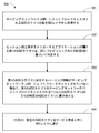
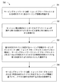
- FIG. 5 is a flowchart showing an example of the operation related to ACDC of the NAS layer 202 of UE1 (processing 500).
- the NAS layer 202 obtains from the RRC layer 203 the number of ACDC categories broadcast by the serving network (eNB2).
- the NAS layer 202 determines the first ACDC category to which the application that triggers the session establishment request belongs based on the ACDC settings 410 provisioned to UE1 by the home network operator.
- the NAS layer 202 may include one or more ACDCs broadcast by the serving network. Replace with a specific ACDC category in the category.
- the NAS layer 202 passes the specific ACDC category (substitute) along with the service request to the RRC layer 203.
- a new call type may be defined for the NAS layer 202 to pass the ACDC category along with the service request to the RRC layer 203.
- the NAS layer 202 requests the RRC layer 203 to establish a NAS signaling connection for transmitting an initialRRNAS message (e.g., ⁇ ⁇ ⁇ ⁇ ⁇ ⁇ Service Request)
- the NAS layer 202 notifies the RRC layer 203 of the call type (call type).
- Existing call types indicate “originating calls”, “” terminating calls ”,“ emergency calls ”, or“ originating signaling ”In addition to these, if the application that triggers session establishment belongs to ACDC category X
- the call type may be, for example, “ACDC Cat-X originating calls.”
- the RRC layer 203 Upon receipt of the new call type, the RRC layer 203 triggers an access attempt (an attempt to establish an RRC connection). You can know the ACDC category to which the belongs.
- a new information element separate from the call type may be defined to represent the ACDC category.
- the new information element may be, for example, “ACDC Category Indication”, “Established ACDC Category”, “Triggered ACDC category”, “Selected ACDC Category”, or “Assigned ACDC Category”.
- the NAS layer 202 may pass the new information element to the RRC layer 203 together with the initial NAS message (e.g., Service Request) and call type (e.g., originating calls).
- the RRC layer 203 can know the ACDC category to which the application that triggers the access attempt (RRC connection establishment attempt) belongs.
- burring information corresponding to the first ACDC category to which the application that triggers the session establishment request belongs is transmitted by the serving network (eNB2).
- the serving network eNB2
- the NAS layer 202 replaces the first ACDC category with a substitute ACDC category and informs (passes) the substitute ACDC category to the RRC layer 203.
- the surrogate ACDC category is one of one or more ACDC categories broadcast by the serving network. In other words, if the serving network (eNB2) broadcasts an ACDC category (categories) that is less than the ACDC configuration 410 provisioned to UE1, the NAS layer 202 is included in the ACDC configuration 410 of UE1.
- the ACDC categories are replaced. Then, the RRC layer 203 performs an ACDC check based on burring information broadcast from the serving network (eNB2) and corresponding to the substitute ACDC category.
- the NAS layer 202 of the UE1 can replace the ACDC category, and the RRC layer 203 of the UE1 can perform the ACDC check.
- the NAS layer 202 may release information of a specific (alternative) ACDC category each time UE1 changes the serving cell.
- the NAS layer 202 may retain information on a specific ACDC category even if the serving cell is changed. For example, while the UE 1 selects the same PLMN (or the same serving network) and the ACDC function is enabled in the changed serving cell, the NAS layer 202 holds information on a specific ACDC category. May be.
- FIG. 6 shows an example of ACDC operation by UE1.
- eNB2 transmits ACDC control information to UE1 (601).
- the ACDC control information includes a plurality of ACDC categories and burring information for each ACDC category.
- the eNB 2 may include the ACDC control information in the broadcast information (eg, SIB information) broadcast in the cell 21 so that the UE 1 in the idle mode (ECM-IDLE and RRC_IDLE) can receive the ACDC control information. Good.
- the NAS layer 202 In response to receiving a data transmission request (in other words, a session establishment request) 602 from the application layer 201, the NAS layer 202, if UE1 is in idle mode (ECM-IDLE), triggers the application that triggered the request.
- the application identifier (identifier) is determined.
- the application identifier may include an OS App ID or an OS App ID.
- the NAS layer 202 determines to which ACDC category the application that triggered the request belongs based on the ACDC configuration (configuration) 610 (603).
- the ACDC setting (configuration) 610 is the same as the ACDC setting 410 shown in FIG.
- the ACDC setting 610 indicates mapping between a plurality of applications (application identifiers) installed in the UE 1 and a plurality of ACDC categories.
- the ACDC setting 610 is provisioned to the UE 1 via, for example, OMA-DM or USIM.
- the NAS layer 202 indicates the ACDC category to which the application that triggers the session establishment request belongs (that is, the ACDC category derived from the ACDC setting 610) together with the NAS message (ie, ServiceSRRequest (SR)) for session establishment. (604).
- ACDC category to which the application that triggers the session establishment request belongs (that is, the ACDC category derived from the ACDC setting 610) together with the NAS message (ie, ServiceSRRequest (SR)) for session establishment. (604).
- the serving network eNB2 broadcasts ACDC categories (categories) that are less than the ACDC configuration 410 provisioned to UE1, the application that triggers the session establishment request belongs.
- the ACDC category referred to as the first ACDC category
- the corresponding burring information may not be broadcast by the serving network (eNB2).
- the ACDC category to which the application that triggers the session establishment request belongs may be an unmatched ACDC category.
- the “unmatched ACDC category” here is an ACDC category in which the ACDC category is set to UE1, but the corresponding burring information is not broadcast from the serving network (eNB2).
- the RRC layer 203 when the burring information corresponding to the first ACDC category is not broadcast by the serving network (eNB2), the RRC layer 203 specifies the one or more ACDC categories broadcast by the serving network.
- the ACDC category is selected in place of the first ACDC category (605).
- the RRC layer 203 replaces the first ACDC category with a specific ACDC category (substitute) (605).
- the RRC layer 203 considers that the application that triggers the session establishment request belongs to a specific ACDC category broadcast by the serving network instead of the first ACDC category (605).
- the serving network eNB2 broadcasts less ACDC categories (categories) than the ACDC settings 610 provisioned to UE1, the RRC layer 203 is included in the ACDC settings 610 of UE1.
- an ACDC category replacement is performed (605).
- the RRC layer 203 determines that the first ACDC category value is greater than the maximum value of one or more ACDC categories broadcast by the serving network (ie, the lowest ACDC category value). Instead of the value of, it may be replaced by the value of a specific ACDC category (substitute). That is, the RRC layer 203 may use the value of a specific ACDC category (substitute) instead of the value of the first ACDC category.
- the RRC layer 203 identifies the value of the first ACDC category when the value of the ACDC category (and its burring information) corresponding to the value of the first ACDC category is not broadcast by the serving network. May be replaced by the value of the ACDC category. That is, the RRC layer 203 may use the value of a specific ACDC category (substitute) instead of the value of the first ACDC category.
- the particular ACDC category (alternative ACDC category) selected by the RRC layer 203 may be the lowest ACDC category of one or more ACDC categories broadcast by the serving network (eNB2). . Such replacement of the ACDC category may be preferable because it follows the handling of the unmatched ACDC category described in Non-Patent Document 1.
- the specific ACDC category (substitute ACDC category) selected by the RRC layer 203 may not be the lowest ACDC category in the serving network (eNB2).
- the RRC layer 203 follows a predetermined mapping rule.
- the particular ACDC category (substitute ACDC category) to be replaced by the first ACDC category may be determined.
- the mapping rule defines a mapping between a plurality of (possibly) ACDC categories broadcast by the serving network and one or more ACDC categories provisioned to UE1.
- the said mapping rule may be provisioned by UE1 and may be sent to UE1 from a serving network (eNB2).
- the RRC layer 203 performs an ACDC check based on burring information broadcast from the serving network (eNB2) and corresponding to the substitute ACDC category (606). That is, the RRC layer 203 permits an access attempt triggered by a Service Request from the NAS layer 202 based on burring information corresponding to a specific ACDC category (substitute ACDC category) broadcast by the serving network (eNB2). Control whether to do.
- FIG. 7 is a flowchart showing an example of operation related to ACDC of the RRC layer 203 of UE1 (processing 700).
- the RRC layer 203 receives one or more ACDC categories and burring information broadcast by the serving network (eNB2).
- eNB2 serving network
- the RRC layer 203 receives the first ACDC category to which the application that triggers the session establishment request belongs from the NAS layer 202 together with the service request.
- the first ACDC category is derived by the NAS layer 202 from the ACDC configuration 610 provisioned to UE1.
- the RRC layer 203 may identify a particular one of the one or more ACDC categories broadcast by the serving network. Select the ACDC category as an alternative to the first ACDC category.
- the RRC layer 203 controls whether to allow an access attempt based on burring information broadcast by the serving network (eNB2) and corresponding to a specific ACDC category.
- a new call type may be defined for the NAS layer 202 to pass the ACDC category together with the service request to the RRC layer 203.
- the NAS layer 202 requests the RRC layer 203 to establish a NAS signaling connection for transmitting an initialRRNAS message (e.g., ⁇ ⁇ ⁇ ⁇ ⁇ ⁇ Service Request)
- the NAS layer 202 notifies the RRC layer 203 of the call type (call type).
- Existing call types indicate “originating calls”, “” terminating calls ”,“ emergency calls ”, or“ originating signaling ”In addition to these, if the application that triggers session establishment belongs to ACDC category X
- the call type may be, for example, “ACDC Cat-X originating calls”.
- the RRC layer 203 can know the first ACDC category to which the application that triggers the access trial (RRC connection establishment trial) belongs.
- the RRC layer 203 cannot recognize the new call type when the burring information corresponding to the first ACDC category specified by the new call type is not broadcast by the serving network, or the RRC layer 203 cannot recognize the new call type (or The RRC layer 203 may select an alternate ACDC category if the call type is unknown (“unknown” call “type”).
- a new information element separate from the call type may be defined to represent the ACDC category.
- the new information element may be, for example, “ACDC Category Indication”, “Established ACDC Category”, “Triggered ACDC category”, “Selected ACDC Category”, or “Assigned ACDC Category”.
- the NAS layer 202 may pass the new information element to the RRC layer 203 together with the initial NAS message (e.g., Service Request) and call type (e.g., originating calls).
- the RRC layer 203 can know the first ACDC category to which the application that triggers the access trial (RRC connection establishment trial) belongs.
- the RRC layer 203 When the burring information corresponding to the first ACDC category specified by the new information element is not broadcast by the serving network, or the RRC layer 203 sets the first ACDC category specified by the new information element. If it is not recognizable (or the first ACDC category is unknown category “unknown” ACDC category), the RRC layer 203 may select an alternative ACDC category.
- burring information corresponding to the first ACDC category to which the application that triggers the session establishment request belongs is provided by the serving network (eNB2).
- the RRC layer 203 selects a substitute ACDC category instead of the first ACDC category, and is based on burring information broadcast from the serving network (eNB2) and corresponding to the substitute ACDC category. Perform ACDC check.
- the serving network (eNB2) broadcasts ACDC categories (categories) less than the ACDC configuration 610 provisioned to UE1
- the RRC layer 203 is included in the ACDC configuration 610 of UE1.
- the ACDC categories are replaced.
- the RRC layer 203 of UE1 can perform ACDC category replacement and ACDC check.
- a modified example of the ACDC operation in the UE 1 described in the first and second embodiments will be described.
- the configuration example of the wireless communication network according to the present embodiment is the same as in FIG. 1, and the control plane protocol stack of UE1 is the same as in FIG.
- the serving network eNB2
- ACDC categories categories
- the NAS layer 202 or the RRC layer 203 selects a substitute ACDC category.
- the NAS layer 202 or the RRC layer 203 may select a substitute ACDC category according to the mapping rule sent from the serving network (eNB2).
- the mapping rule defines a mapping between a plurality of (possibly) ACDC categories broadcast by the serving network and one or more ACDC categories provisioned to UE1.
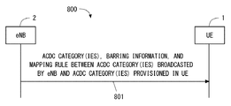
- FIG. 8 is a sequence diagram showing an example of the procedure for sending the mapping rule from the eNB 2 to the UE 1 (process 800).
- the eNB 2 includes a plurality of ACDC categories used in the cell 21, burring information for each ACDC category, a plurality of ACDC categories broadcast by the eNB 2, and a plurality of ACDC categories provisioned to the UE1.
- the mapping rule between is transmitted to UE1.
- the eNB 2 may broadcast broadcast information (SIB information) including these in the cell 21.
- SIB information broadcast broadcast information
- the mapping rule associates the highest ACDC category in UE1's ACDC configuration with the highest ACDC category in the serving network, and associates the second and third ACDC categories in UE1's ACDC configuration with the serving network second category.
- the 4th and 5th ACDC categories in UE1's ACDC configuration may be associated with the 3rd (lowest) ACDC category of the serving network.
- eNB2 has a plurality of candidate values (eg, 4, 5, 6,%) Of the number of ACDC categories provisioned to UE1 by the number of ACDC categories (eg, 3) used in the serving network (eNB2).
- a plurality of mapping rules may be provided to UE1 to associate with.
- the serving network (eNB2) can explicitly specify the mapping between the number of ACDC categories used in the serving network (eNB2) and the number of ACDC categories provisioned to the UE1 to the UE1. .
- the AS layer 208 may release information on a specific (alternative) ACDC category each time the UE1 changes the serving cell. Instead, the AS layer 208 (RRC layer 203) may retain information on a specific ACDC category even if the serving cell is changed. For example, while the UE 1 selects the same PLMN (or the same serving network) and the ACDC function is enabled in the changed serving cell, the AS layer 208 (RRC layer 203) has a specific ACDC category. May be retained.
- ACDC is applied to UE1 in connected mode (eg, RRC_CONNECTED). That is, when UE1 already in the connected mode tries to start a new application (or service), it is assumed that ACDC is used in UE1. In this case, ACDC is considered to realize service request control (that is, service request restriction) for the RRC_CONNECTED terminal instead of access control (that is, access restriction) for the RRC_IDLE terminal.
- service request control that is, service request restriction
- access control that is, access restriction
- control (restriction) of the service request in UE1 which is RRC_CONNECTED is a scheduling request for UE1 to allocate uplink resources to eNB2 in order to transmit a service request for starting the application (or service). May be limited (suppressed).
- the control resource Physical Uplink Control Chanel (PUCCH)
- PUCCH Physical Uplink Control Chanel
- the control (restriction) of the service request in UE1 being RRC_CONNECTED is the restriction (suppression) of the start of random access procedure (ie, transmission of random access preamble) It may be.
- UE1 may execute the following procedure, for example.
- UE1 establishes a radio connection (RRC Connection) with eNB2 in cell 21 of eNB2, and enters an RRC_CONNECTED state.
- RRC Connection radio connection
- UE1 may have entered the RRC_CONNECTED state after executing ACDC (that is, after performing access control by ACDC).
- ACDC is not enabled in the serving cell (for the serving network of the PLMN selected by the NAS layer of UE1) (that is, eNB2 receives ACDC control information). Therefore, UE1 may have entered the RRC_CONNECTED state without executing ACDC.
- UE1 determines whether ACDC is enabled in the serving cell (that is, whether eNB2 is reporting ACDC control information) Confirm).
- ACDC is enabled
- the NAS layer or RRC layer of UE1 matches the ACDC setting provisioned to UE1 with the ACDC control information broadcast in the serving cell.
- the NAS layer or RRC layer of UE1 confirms whether burring information corresponding to the first ACDC category corresponding to the application (or service) is broadcast. If the burring information corresponding to the first ACDC category is not broadcast, UE1 selects a specific ACDC category instead. Note that the same procedure as in the first embodiment or the second embodiment can be applied to the matching between the ACDC setting and the ACDC control information, and detailed description thereof is omitted.
- the RRC layer of UE1 is based on the burring information corresponding to the first ACDC category or the replaced specific ACDC category, for example, a service request (eg, an instruction for sending a Scheduling request to the MAC layer, or a random access procedure. Start instructions).
- a service request eg, an instruction for sending a Scheduling request to the MAC layer, or a random access procedure. Start instructions.
- the service request is not permitted for the application (or service) by the burring information, the service request in the serving cell is not performed until a predetermined period or ACDC is invalidated.
- the service request may be made based on the probability.
- access control in this case, restriction of service request
- ACDC for the RRC_CONNECTED terminal may be performed for each terminal or for each terminal group.
- eNB2 may transmit at least one part of ACDC control information to UE1 with a terminal individual message (e.g., RRC Connection Reconfiguration message).
- the UE 1 may use the setting specified by the terminal individual message in preference to the setting specified by the broadcast ACDC control information.
- FIG. 9 is a block diagram illustrating a configuration example of UE1.
- the Radio-Frequency (RF) transceiver 901 performs analog RF signal processing to communicate with the eNB 2.
- Analog RF signal processing performed by the RF transceiver 901 includes frequency up-conversion, frequency down-conversion, and amplification.
- RF transceiver 901 is coupled with antenna 902 and baseband processor 903. That is, the RF transceiver 901 receives modulation symbol data (or OFDM symbol data) from the baseband processor 903, generates a transmission RF signal, and supplies the transmission RF signal to the antenna 902. Further, the RF transceiver 901 generates a baseband received signal based on the received RF signal received by the antenna 902 and supplies this to the baseband processor 903.
- modulation symbol data or OFDM symbol data
- the baseband processor 903 performs digital baseband signal processing (data plane processing) and control plane processing for wireless communication.
- Digital baseband signal processing consists of (a) data compression / decompression, (b) data segmentation / concatenation, (c) ⁇ transmission format (transmission frame) generation / decomposition, and (d) transmission path encoding / decoding. , (E) modulation (symbol mapping) / demodulation, and (f) generation of OFDM symbol data (baseband OFDM signal) by Inverse Fast Fourier Transform (IFFT).
- control plane processing includes layer 1 (eg, transmission power control), layer 2 (eg, radio resource management, hybrid automatic repeat request (HARQ) processing), and layer 3 (eg, attach, mobility, and call management). Communication management).
- the digital baseband signal processing by the baseband processor 903 includes signal processing of the Packet Data Convergence Protocol (PDCP) layer, Radio Link Control (RLC) layer, MAC layer, and PHY layer. But you can.
- the control plane processing by the baseband processor 903 may include Non-Access Stratum (NAS) protocol, RRC protocol, and MAC CE processing.
- NAS Non-Access Stratum
- the baseband processor 903 includes a modem processor (eg, Digital Signal Processor (DSP)) that performs digital baseband signal processing and a protocol stack processor (eg, Central Processing Unit (CPU), or Micro Processing Unit (CPU) that performs control plane processing. (MPU)).
- DSP Digital Signal Processor
- protocol stack processor eg, Central Processing Unit (CPU), or Micro Processing Unit (CPU) that performs control plane processing. (MPU)
- a protocol stack processor that performs control plane processing may be shared with an application processor 904 described later.
- the application processor 904 is also called a CPU, MPU, microprocessor, or processor core.
- the application processor 904 may include a plurality of processors (a plurality of processor cores).
- the application processor 904 is a system software program (Operating System (OS)) read from the memory 906 or a memory (not shown) and various application programs (for example, a call application, a web browser, a mailer, a camera operation application, music playback)
- OS Operating System
- application programs for example, a call application, a web browser, a mailer, a camera operation application, music playback
- Various functions of UE1 are realized by executing (application).
- the baseband processor 903 and the application processor 904 may be integrated on a single chip, as indicated by the dashed line (905) in FIG.
- the baseband processor 903 and the application processor 904 may be implemented as one System on Chip (SoC) device 905.
- SoC System on Chip
- An SoC device is sometimes called a system Large Scale Integration (LSI) or chipset.
- the memory 906 is a volatile memory, a nonvolatile memory, or a combination thereof.
- the memory 906 may include a plurality of physically independent memory devices.
- the volatile memory is, for example, Static Random Access Memory (SRAM), Dynamic RAM (DRAM), or a combination thereof.
- the non-volatile memory is a mask Read Only Memory (MROM), Electrically Erasable Programmable ROM (EEPROM), flash memory, hard disk drive, or any combination thereof.
- the memory 906 may include an external memory device accessible from the baseband processor 903, the application processor 904, and the SoC 905.
- Memory 906 may include an embedded memory device integrated within baseband processor 903, application processor 904, or SoC 905.
- the memory 906 may include a memory in a Universal Integrated Circuit Card (UICC).
- UICC Universal Integrated Circuit Card
- the memory 906 may store a software module (computer program) including an instruction group and data for performing processing by the UE 1 described in the above-described embodiments.
- the baseband processor 903 or the application processor 904 may be configured to perform the processing of the UE 1 described in the above-described embodiment by reading and executing the software module from the memory 906.
- FIG. 10 is a block diagram illustrating a configuration example of the base station (eNB) 2 according to the above-described embodiment.
- the base station 2 includes an RF transceiver 1001, a network interface 1003, a processor 1004, and a memory 1005.
- the RF transceiver 1001 performs analog RF signal processing to communicate with the wireless terminal 1.
- the RF transceiver 1001 may include multiple transceivers.
- RF transceiver 1001 is coupled to antenna 1002 and processor 1004.
- the RF transceiver 1001 receives modulation symbol data (or OFDM symbol data) from the processor 1004, generates a transmission RF signal, and supplies the transmission RF signal to the antenna 1002. Further, the RF transceiver 1001 generates a baseband received signal based on the received RF signal received by the antenna 1002, and supplies this to the processor 1004.
- the network interface 1003 is used to communicate with network nodes (e.g., Mobility Management Entity (MME) and Serving Gateway (S-GW)).
- MME Mobility Management Entity
- S-GW Serving Gateway
- the network interface 1003 may include, for example, a network interface card (NIC) compliant with IEEE 802.3 series.
- NIC network interface card
- the processor 1004 performs digital baseband signal processing (data plane processing) and control plane processing for wireless communication.
- the digital baseband signal processing by the processor 1004 may include signal processing of a PDCP layer, an RLC layer, a MAC layer, and a PHY layer.
- the control plane processing by the processor 1004 may include S1 protocol, RRC protocol, and MAC-CE processing.
- the processor 1004 may include a plurality of processors.
- the processor 1004 may include a modem processor (e.g., DSP) that performs digital baseband signal processing and a protocol stack processor (e.g., CPU or MPU) that performs control plane processing.
- DSP digital baseband signal processing
- protocol stack processor e.g., CPU or MPU
- the memory 1005 is configured by a combination of a volatile memory and a nonvolatile memory.
- the volatile memory is, for example, SRAM or DRAM or a combination thereof.
- the non-volatile memory is, for example, an MROM, PROM, flash memory, hard disk drive, or a combination thereof.
- Memory 1005 may include storage located remotely from processor 1004. In this case, the processor 1004 may access the memory 1005 via the network interface 1003 or an I / O interface not shown.
- the memory 1005 may store a software module (computer program) including an instruction group and data for performing processing by the base station 2 described in the above embodiments.
- the processor 1004 may be configured to perform the processing of the base station 2 described in the above embodiments by reading the software module from the memory 1005 and executing the software module.
- each of the processors included in the UE 1 and the eNB 2 includes a group of instructions for causing a computer to execute the algorithm described with reference to the drawings. Run multiple programs.
- the program can be stored and supplied to a computer using various types of non-transitory computer readable media.
- Non-transitory computer readable media include various types of tangible storage media (tangible storage medium).
- non-transitory computer-readable media are magnetic recording media (eg flexible disks, magnetic tapes, hard disk drives), magneto-optical recording media (eg magneto-optical discs), Compact Disc Read Only Memory (CD-ROM), CD-ROM R, CD-R / W, semiconductor memory (for example, mask ROM, Programmable ROM (PROM), Erasable PROM (EPROM), flash ROM, Random Access Memory (RAM)).
- the program may also be supplied to the computer by various types of temporary computer-readable media. Examples of transitory computer readable media include electrical signals, optical signals, and electromagnetic waves.
- the temporary computer-readable medium can supply the program to the computer via a wired communication path such as an electric wire and an optical fiber, or a wireless communication path.
- the UE 1 (NAS layer 202 or AS layer 208) that can retain information of a specific ACDC category even if the serving cell is changed, which has been described as an example in the above-described embodiment, is another network (second network) having a different PLMN identity. If the serving network (eNB2) is changed to the network), the specific ACDC category that was selected, replaced, or considered as belonging to the first ACDC category for the previous serving network (first network) May be discarded, released or modified.
- the case where UE1 changes the serving network to the second network may be a case where UE1 performs handover (Inter-PLMN ⁇ ⁇ ⁇ ⁇ ⁇ ⁇ HO) from the first network to the second network. It may be a case where the serving network is changed from the first network to the second network by performing network selection (PLMN selection) in the idle mode (eg, RRC_IDLE).
- PLMN selection in the idle mode
- UE1 has selected and replaced the first ACDC category for the first network in response to receiving information of one or more ACDC categories broadcast from the second network. Or, a particular ACDC category deemed to belong may be discarded, released, or modified.
- the NAS layer 202 includes information on one or more ACDC categories broadcast by the second network and the number of ACDC categories broadcast (the number of broadcasted ACDC category (ies)).
- the previous configuration in the NAS layer 202 ie, a specific ACDC category for substitution
- release release
- the RRC layer 203 responds to the reception of the ACDC control information broadcasted by the second network (501), in response to the previous setting in the RRC layer 203 (ie, the substitute specific ACDC category). ) May be discarded, released, or modified, but is not limited thereto.
- the serving network is changed to the second network of the other PLMN.
- the eNB 2 may share information (e.g., ACDC control information, presence / absence of execution of ACDC) related to ACDC in its own cell with other neighboring eNBs. Moreover, eNB2 may transmit the information regarding ACDC in the adjacent cell (For example, the other cell of the said eNB2 itself, the cell of other eNB) in an own cell. UE1 may perform cell reselection based on the information regarding ACDC in the adjacent cell.
- information e.g., ACDC control information, presence / absence of execution of ACDC
- Wireless terminal UE 2
- Base station eNB
- RF radio frequency
- baseband processor 901 radio frequency (RF) transceiver
- application processor 906 memory
- RF transceiver 1004 processor 1005 memory
Landscapes
- Engineering & Computer Science (AREA)
- Computer Networks & Wireless Communication (AREA)
- Signal Processing (AREA)
- Computer Security & Cryptography (AREA)
- Multimedia (AREA)
- Mobile Radio Communication Systems (AREA)
Abstract
Selon un mode de réalisation de la présente invention, une couche NAS (202) d'un terminal sans fil (1) acquiert une ou plusieurs catégories d'interdiction d'accès (401) notifiées par un réseau de desserte (2), ou le nombre de ces dernières, à partir d'une couche AS (208) du terminal sans fil (1). Lorsque des informations d'interdiction correspondant à une première catégorie d'interdiction d'accès (404) à laquelle appartient une application qui déclenche une requête d'établissement de session (403) ne sont pas notifiées par un nœud B évolué (eNB) (2), la couche NAS (202) remplace la première catégorie d'interdiction d'accès (404) par une catégorie d'interdiction d'accès spécifique parmi ladite ou lesdites catégories d'interdiction d'accès (401) notifiées par le réseau de desserte (2).
Priority Applications (5)
| Application Number | Priority Date | Filing Date | Title |
|---|---|---|---|
| EP16829999.8A EP3331285B1 (fr) | 2015-07-28 | 2016-06-21 | Terminal sans fil, station de base et procédé correspondant |
| JP2017530994A JP6822402B2 (ja) | 2015-07-28 | 2016-06-21 | 無線端末及びその方法 |
| US15/748,026 US10631233B2 (en) | 2015-07-28 | 2016-06-21 | Radio terminal, base station, and method therefor |
| US16/820,127 US11265804B2 (en) | 2015-07-28 | 2020-03-16 | Radio terminal, base station, and method therefor |
| US17/564,627 US11729704B2 (en) | 2015-07-28 | 2021-12-29 | Radio terminal, base station, and method therefor |
Applications Claiming Priority (2)
| Application Number | Priority Date | Filing Date | Title |
|---|---|---|---|
| JP2015-148790 | 2015-07-28 | ||
| JP2015148790 | 2015-07-28 |
Related Child Applications (2)
| Application Number | Title | Priority Date | Filing Date |
|---|---|---|---|
| US15/748,026 A-371-Of-International US10631233B2 (en) | 2015-07-28 | 2016-06-21 | Radio terminal, base station, and method therefor |
| US16/820,127 Continuation US11265804B2 (en) | 2015-07-28 | 2020-03-16 | Radio terminal, base station, and method therefor |
Publications (1)
| Publication Number | Publication Date |
|---|---|
| WO2017017890A1 true WO2017017890A1 (fr) | 2017-02-02 |
Family
ID=57884438
Family Applications (1)
| Application Number | Title | Priority Date | Filing Date |
|---|---|---|---|
| PCT/JP2016/002976 Ceased WO2017017890A1 (fr) | 2015-07-28 | 2016-06-21 | Terminal sans fil, station de base et procédé correspondant |
Country Status (4)
| Country | Link |
|---|---|
| US (3) | US10631233B2 (fr) |
| EP (1) | EP3331285B1 (fr) |
| JP (1) | JP6822402B2 (fr) |
| WO (1) | WO2017017890A1 (fr) |
Cited By (8)
| Publication number | Priority date | Publication date | Assignee | Title |
|---|---|---|---|---|
| WO2018204609A1 (fr) | 2017-05-05 | 2018-11-08 | Intel IP Corporation | Mécanisme de contrôle d'accès |
| KR20190085454A (ko) * | 2018-01-10 | 2019-07-18 | 삼성전자주식회사 | 무선통신 시스템에서 통신 방법 및 장치 |
| KR20200034794A (ko) * | 2017-08-09 | 2020-03-31 | 콘비다 와이어리스, 엘엘씨 | 5g 엔알에서의 액세스 제어 |
| JP2021529485A (ja) * | 2018-07-02 | 2021-10-28 | ノキア テクノロジーズ オサケユイチア | 接続モードのユーザ機器のアクセス制御 |
| US11246183B2 (en) | 2017-08-03 | 2022-02-08 | Samsung Electronics Co., Ltd. | Method and apparatus for controlling access in next generation mobile communication system |
| TWI757481B (zh) * | 2017-05-06 | 2022-03-11 | 美商高通公司 | 統一存取控制 |
| US11445404B2 (en) | 2018-01-10 | 2022-09-13 | Samsung Electronics Co., Ltd. | Method and apparatus for wireless communication in wireless communication system |
| US12382333B2 (en) | 2013-08-30 | 2025-08-05 | Interdigital Patent Holdings, Inc. | Methods for application specific access control |
Families Citing this family (11)
| Publication number | Priority date | Publication date | Assignee | Title |
|---|---|---|---|---|
| WO2017017890A1 (fr) * | 2015-07-28 | 2017-02-02 | 日本電気株式会社 | Terminal sans fil, station de base et procédé correspondant |
| WO2017052253A1 (fr) * | 2015-09-23 | 2017-03-30 | Lg Electronics Inc. | Procédé et appareil permettant de réaliser un contrôle de congestion spécifique à une application pour la communication de données au sein d'un système de communication sans fil |
| CN109565742B (zh) * | 2016-07-05 | 2021-06-29 | Lg 电子株式会社 | 在下一代移动通信网络中执行接入控制的方法和用户设备 |
| CN115665857B (zh) | 2016-07-13 | 2026-02-03 | 三星电子株式会社 | 在移动通信中使用的接入控制方法和装置 |
| US11160007B2 (en) * | 2017-01-06 | 2021-10-26 | Lg Electronics Inc. | Method and terminal for carrying out access control in 5th generation mobile communication system |
| KR102222830B1 (ko) * | 2017-03-21 | 2021-03-04 | 삼성전자 주식회사 | 이동통신에서 연결 모드의 비연속 수신 모드를 지원하는 방법 및 장치 |
| US10666513B2 (en) * | 2017-05-03 | 2020-05-26 | International Business Machines Corporation | Filesystem share auto-detect |
| US10798648B2 (en) * | 2017-08-11 | 2020-10-06 | Lg Electronics Inc. | Method for performing PLMN selection and device supporting the same |
| CN112262595A (zh) * | 2018-06-07 | 2021-01-22 | 华为技术有限公司 | 一种发送业务请求的方法、装置及系统 |
| CN111654894B (zh) * | 2018-06-26 | 2022-08-30 | 北京小米移动软件有限公司 | 接入控制ac限制方法及装置 |
| ES2972343T3 (es) * | 2021-05-26 | 2024-06-12 | Deutsche Telekom Ag | Procedimientos para la generación y transmisión de información del sistema, SI, en una red de telecomunicaciones móviles, MN, y sus MN correspondientes. |
Citations (1)
| Publication number | Priority date | Publication date | Assignee | Title |
|---|---|---|---|---|
| WO2014160611A1 (fr) * | 2013-03-29 | 2014-10-02 | Intel IP Corporation | Provisionnement de catégories d'application au niveau d'un équipement utilisateur durant une congestion de réseau |
Family Cites Families (7)
| Publication number | Priority date | Publication date | Assignee | Title |
|---|---|---|---|---|
| JP4999902B2 (ja) * | 2009-10-05 | 2012-08-15 | 株式会社エヌ・ティ・ティ・ドコモ | 移動局 |
| US8738075B2 (en) * | 2011-08-10 | 2014-05-27 | Nokia Siemens Networks Oy | Methods and apparatus for radio resource control |
| US9743341B2 (en) * | 2013-03-29 | 2017-08-22 | Intel IP Corporation | Provisioning of application categories at a user equipment during network congestion |
| JP6507425B2 (ja) * | 2014-01-24 | 2019-05-08 | シャープ株式会社 | 端末装置、アクセス制御方法および集積回路 |
| CN106068660B (zh) * | 2014-11-10 | 2019-11-26 | Lg 电子株式会社 | 通过acdc阻止网络接入的方法和用户设备 |
| US9641993B2 (en) * | 2015-06-30 | 2017-05-02 | Verizon Patent And Licensing Inc. | Access class barring and redirecting of emergency calls |
| WO2017017890A1 (fr) * | 2015-07-28 | 2017-02-02 | 日本電気株式会社 | Terminal sans fil, station de base et procédé correspondant |
-
2016
- 2016-06-21 WO PCT/JP2016/002976 patent/WO2017017890A1/fr not_active Ceased
- 2016-06-21 EP EP16829999.8A patent/EP3331285B1/fr active Active
- 2016-06-21 US US15/748,026 patent/US10631233B2/en active Active
- 2016-06-21 JP JP2017530994A patent/JP6822402B2/ja active Active
-
2020
- 2020-03-16 US US16/820,127 patent/US11265804B2/en active Active
-
2021
- 2021-12-29 US US17/564,627 patent/US11729704B2/en active Active
Patent Citations (1)
| Publication number | Priority date | Publication date | Assignee | Title |
|---|---|---|---|---|
| WO2014160611A1 (fr) * | 2013-03-29 | 2014-10-02 | Intel IP Corporation | Provisionnement de catégories d'application au niveau d'un équipement utilisateur durant une congestion de réseau |
Non-Patent Citations (4)
| Title |
|---|
| HUAWEI ET AL.: "Discussion on stage 3 implementation of ACDC categories", 3GPP TSG-CT WG1#92 CL-151890, 18 May 2015 (2015-05-18), XP050975764, Retrieved from the Internet <URL:http://www.3gpp.org/ftp/tsg_ct/WG1_mm-cc-sm_ ex- CN 1/TSGC1_92_Sanya/docs/C1-151890.zip> * |
| INTEL CORPORATION: "Considerations on RAN2 impacts to support ACDC requirements", 3GPP TSG-RAN WG2#90 R2-152151, 16 May 2015 (2015-05-16), XP050973454, Retrieved from the Internet <URL:http://www.3gpp.org/ftp/tsg_ran/WG2_RL2/TSGR2_ 90/Docs/R2-152151.zip> * |
| NEC: "ACDC Category handling", 3GPP TSG- RAN WG2#91 R2-153455, 14 August 2015 (2015-08-14), XP050993801, Retrieved from the Internet <URL:http://www. 3gpp.org/ftp/tsg_ran/WG2_RL2/TSGR2_91/Docs/R2- 153455.zip> * |
| NOKIA NETWORKS: "ACDC impacts on RAN", 3GPP TSG-RAN WG2#90 R2-152391, 16 May 2015 (2015-05-16), XP050971040, Retrieved from the Internet <URL:http://www.3gpp.org/ftp/tsg_ran/WG2_RL2/TSGR2_ 90/Docs/R2-152391.zip> * |
Cited By (21)
| Publication number | Priority date | Publication date | Assignee | Title |
|---|---|---|---|---|
| US12382333B2 (en) | 2013-08-30 | 2025-08-05 | Interdigital Patent Holdings, Inc. | Methods for application specific access control |
| EP4138461A1 (fr) * | 2017-05-05 | 2023-02-22 | Apple Inc. | Mécanisme de contrôle d'accès |
| CN110574431A (zh) * | 2017-05-05 | 2019-12-13 | 英特尔Ip公司 | 接入控制机制 |
| WO2018204609A1 (fr) | 2017-05-05 | 2018-11-08 | Intel IP Corporation | Mécanisme de contrôle d'accès |
| EP3619955A4 (fr) * | 2017-05-05 | 2020-12-02 | Intel IP Corporation | Mécanisme de contrôle d'accès |
| US11160006B2 (en) | 2017-05-05 | 2021-10-26 | Apple Inc. | Access control mechanism |
| CN115720358A (zh) * | 2017-05-05 | 2023-02-28 | 苹果公司 | 用于用户设备的方法、无线设备和计算机可读存储介质 |
| TWI757481B (zh) * | 2017-05-06 | 2022-03-11 | 美商高通公司 | 統一存取控制 |
| US12245324B2 (en) | 2017-08-03 | 2025-03-04 | Samsung Electronics Co., Ltd. | Method and apparatus for controlling access in next generation mobile communication system |
| US11246183B2 (en) | 2017-08-03 | 2022-02-08 | Samsung Electronics Co., Ltd. | Method and apparatus for controlling access in next generation mobile communication system |
| JP2024001158A (ja) * | 2017-08-09 | 2024-01-09 | インターデイジタル パテント ホールディングス インコーポレイテッド | 5g nrにおけるアクセス制御 |
| US11805472B2 (en) | 2017-08-09 | 2023-10-31 | Interdigital Patent Holdings, Inc. | Access control in 5G NR |
| JP2020530695A (ja) * | 2017-08-09 | 2020-10-22 | コンヴィーダ ワイヤレス, エルエルシー | 5g nrにおけるアクセス制御 |
| US20240121702A1 (en) | 2017-08-09 | 2024-04-11 | Interdigital Patent Holdings, Inc. | Access control in 5g nr |
| KR102661515B1 (ko) * | 2017-08-09 | 2024-04-29 | 인터디지탈 패튼 홀딩스, 인크 | 5g 엔알에서의 액세스 제어 |
| KR20200034794A (ko) * | 2017-08-09 | 2020-03-31 | 콘비다 와이어리스, 엘엘씨 | 5g 엔알에서의 액세스 제어 |
| US12317170B2 (en) | 2017-08-09 | 2025-05-27 | Interdigital Patent Holdings, Inc. | Access control in 5G NR |
| US11445404B2 (en) | 2018-01-10 | 2022-09-13 | Samsung Electronics Co., Ltd. | Method and apparatus for wireless communication in wireless communication system |
| KR102427826B1 (ko) * | 2018-01-10 | 2022-08-01 | 삼성전자주식회사 | 무선통신 시스템에서 통신 방법 및 장치 |
| KR20190085454A (ko) * | 2018-01-10 | 2019-07-18 | 삼성전자주식회사 | 무선통신 시스템에서 통신 방법 및 장치 |
| JP2021529485A (ja) * | 2018-07-02 | 2021-10-28 | ノキア テクノロジーズ オサケユイチア | 接続モードのユーザ機器のアクセス制御 |
Also Published As
| Publication number | Publication date |
|---|---|
| JP6822402B2 (ja) | 2021-01-27 |
| US20200221370A1 (en) | 2020-07-09 |
| EP3331285A1 (fr) | 2018-06-06 |
| EP3331285B1 (fr) | 2022-03-30 |
| JPWO2017017890A1 (ja) | 2018-06-07 |
| US20220124604A1 (en) | 2022-04-21 |
| US10631233B2 (en) | 2020-04-21 |
| US11265804B2 (en) | 2022-03-01 |
| US20180359681A1 (en) | 2018-12-13 |
| EP3331285A4 (fr) | 2019-01-02 |
| US11729704B2 (en) | 2023-08-15 |
Similar Documents
| Publication | Publication Date | Title |
|---|---|---|
| US11729704B2 (en) | Radio terminal, base station, and method therefor | |
| JP7063404B2 (ja) | gNB及びUE | |
| JP7279773B2 (ja) | 無線端末及びその方法 | |
| JP7290193B2 (ja) | 無線端末及び無線端末における方法 | |
| US20180049259A1 (en) | Apparatus and method for proximity-based service communication | |
| WO2016142973A1 (fr) | Dispositif et procédé de communication de service de proximité | |
| WO2016147235A1 (fr) | Dispositif et procédé de communication de service de proximité | |
| CN104685952A (zh) | 在无线通信系统中基于延迟容忍信息处理操作的方法和支持该方法的设备 | |
| CN114930916B (zh) | 基于ue组的小区重选 | |
| WO2023067999A1 (fr) | Terminal radio et procédé associé | |
| CA3158034C (fr) | Resélection de cellule fondée sur le groupe d’équipement utilisateur | |
| HK40009021A (en) | Paging area update failure handling |
Legal Events
| Date | Code | Title | Description |
|---|---|---|---|
| 121 | Ep: the epo has been informed by wipo that ep was designated in this application |
Ref document number: 16829999 Country of ref document: EP Kind code of ref document: A1 |
|
| ENP | Entry into the national phase |
Ref document number: 2017530994 Country of ref document: JP Kind code of ref document: A |
|
| NENP | Non-entry into the national phase |
Ref country code: DE |
|
| WWE | Wipo information: entry into national phase |
Ref document number: 2016829999 Country of ref document: EP |