WO2017017902A1 - 車両用衝突検知装置 - Google Patents
車両用衝突検知装置 Download PDFInfo
- Publication number
- WO2017017902A1 WO2017017902A1 PCT/JP2016/003193 JP2016003193W WO2017017902A1 WO 2017017902 A1 WO2017017902 A1 WO 2017017902A1 JP 2016003193 W JP2016003193 W JP 2016003193W WO 2017017902 A1 WO2017017902 A1 WO 2017017902A1
- Authority
- WO
- WIPO (PCT)
- Prior art keywords
- bumper cover
- film
- support
- detection device
- vehicle
- Prior art date
- Legal status (The legal status is an assumption and is not a legal conclusion. Google has not performed a legal analysis and makes no representation as to the accuracy of the status listed.)
- Ceased
Links
Images










Classifications
-
- B—PERFORMING OPERATIONS; TRANSPORTING
- B60—VEHICLES IN GENERAL
- B60R—VEHICLES, VEHICLE FITTINGS, OR VEHICLE PARTS, NOT OTHERWISE PROVIDED FOR
- B60R19/00—Wheel guards; Radiator guards, e.g. grilles; Obstruction removers; Fittings damping bouncing force in collisions
- B60R19/02—Bumpers, i.e. impact receiving or absorbing members for protecting vehicles or fending off blows from other vehicles or objects
- B60R19/48—Bumpers, i.e. impact receiving or absorbing members for protecting vehicles or fending off blows from other vehicles or objects combined with, or convertible into, other devices or objects, e.g. bumpers combined with road brushes, bumpers convertible into beds
-
- B—PERFORMING OPERATIONS; TRANSPORTING
- B60—VEHICLES IN GENERAL
- B60R—VEHICLES, VEHICLE FITTINGS, OR VEHICLE PARTS, NOT OTHERWISE PROVIDED FOR
- B60R21/00—Arrangements or fittings on vehicles for protecting or preventing injuries to occupants or pedestrians in case of accidents or other traffic risks
Definitions
- the present disclosure relates to a vehicle collision detection device that detects a collision of a pedestrian or the like with a vehicle.
- the detection tube disposed behind the buffer cannot accurately detect the pressure increase due to the impact due to the collision. Further, in the above-described conventional vehicle collision detection device, it is necessary to arrange the detection tube so as to extend in the vehicle width direction without dropping from the buffer body, which is an impediment to the efficiency of assembly work. It was.
- the present disclosure has been made in view of the above circumstances, and an object thereof is to provide a vehicle collision detection device that can accurately detect that a collision with a vehicle has occurred and can be easily assembled. .
- a vehicle collision detection device is more deformed than a piezoelectric polymer film that generates a predetermined output voltage by being deformed, and a piezoelectric polymer film.
- a film support that has rigidity and includes a support wall that supports at least one surface of the piezoelectric polymer film, is attached to an inner surface of a bumper cover provided at a front portion of the vehicle, and is deformable together with the bumper cover;
- the bumper cover In response to the amount of deformation of the bumper cover, based on the output voltage generated by the piezoelectric polymer film, the bumper cover detects that a collision requiring the operation of a protective device for protecting the collision object has occurred.
- a collision determination unit In response to the amount of deformation of the bumper cover, based on the output voltage generated by the piezoelectric polymer film, the bumper cover detects that a collision requiring the operation of a protective device for protecting the collision object has occurred.
- the piezoelectric polymer film that generates an output voltage corresponding to the amount of deformation of the bumper cover is provided.
- the collision determination part has detected that the collision generate
- the piezoelectric polymer film is supported by a more rigid film support, and the film support is attached to the bumper cover. For this reason, the thin film-like piezoelectric polymer film can be easily assembled to the vehicle, and the vehicle collision detection device can be easily manufactured.
- the vehicle collision detection device according to the present disclosure is not intended to detect only pedestrian collisions, but is intended to detect all collisions that require the pedestrian protection device to be activated.
- FIG. 5 is an exploded cross-sectional view of a sensor unit according to a first modification of the first embodiment.
- FIG. 6 is an exploded cross-sectional view of a sensor unit according to a second modification of the first embodiment.
- the figure showing the back view of the sensor unit shown in FIG. FIG. 8 is an enlarged sectional view showing a different fastening method for the fastening part shown in the IXB part of FIG.
- XIA-XIA cross section of Fig. 10 Sectional drawing showing the state which attached the sensor unit shown to FIG. 11A to the bumper cover Sectional drawing at the time of cutting the sensor unit by the modification of Embodiment 3 in the front-back direction Sectional drawing showing the state which attached the sensor unit shown to FIG.
- Sectional drawing at the time of cutting the state which attached the clearance sonar by Embodiment 4 to the bumper cover in the horizontal direction 13A is an enlarged cross-sectional view showing the XIIIB portion Exploded sectional view of a sensor unit according to Embodiment 5
- Sectional drawing at the time of cutting the sensor unit by Embodiment 6 horizontally Sectional drawing showing the state which attached the sensor unit shown to FIG. 15A to the bumper cover Sectional drawing showing the state which attached the sensor unit by the modification of Embodiment 6 to the bumper cover.
- the top view of the sensor unit by Embodiment 7 XVIIA-XVIIA cross-sectional view of FIG. XVIIB-XVIIB sectional view of FIG.
- the figure which showed the graph showing the output characteristic of the sensor unit by Embodiment 7 The figure which showed the graph showing the output characteristic of the sensor unit as a comparative example Sectional drawing at the time of cut
- Embodiments 1 to 7 will be described below.
- or FIG. 19B shall correspond with the direction for the driver
- the indication “front” indicates that the direction of the arrow corresponds to the front of the vehicle VE.
- the following description focuses on pedestrian collisions with the vehicle VE, but the vehicle collision detection device according to the present disclosure is not intended only for detection of pedestrian collisions, but pedestrians such as bicycles and strollers. All collision detections that require the protection device 5 to operate are intended. (Embodiment 1) Based on FIG. 1 thru
- a front bumper 21 (corresponding to a front portion of the vehicle) is attached to the front end portion of the vehicle VE.
- the front bumper 21 extends in the left-right direction and includes a bumper cover 22 and a bumper absorber 23.
- the bumper cover 22 is formed of a synthetic resin material, and forms a design surface in the front portion of the vehicle VE.
- the bumper absorber 23 is provided behind the bumper cover 22 as an impact absorbing material when a collision occurs in the front bumper 21.
- the bumper absorber 23 is made of a foamed resin such as foamed polypropylene, for example.
- the bumper absorber 23 is attached to the front surface 24a of the bumper reinforcement 24 at the rear end surface 23a.
- the bumper reinforcement 24 is a strength member having a hollow interior made of a metal material such as an aluminum alloy, and extends in the left-right direction.
- the bumper reinforcement 24 is fixed to front ends of a pair of left and right side members 25R and 25L extending in the front-rear direction.
- the body unit 2 is formed by the front bumper 21, the bumper reinforcement 24, and the side members 25R and 25L described above.
- the sensor unit 3 is attached to the rear surface 22a (corresponding to the inner surface of the bumper cover) which is the rear surface of the bumper cover 22.
- the sensor unit 3 may be attached to a height at which a pedestrian or the like collides on the vehicle VE.
- the entire outer peripheral surface of the piezo film 31 (corresponding to the piezoelectric polymer film) is covered with the sensor housing 32 (corresponding to the film support). It is formed by.
- the piezo film 31 is integrally formed with the sensor housing 32 by insert molding or the like.
- the sensor unit 3 extends in the vehicle width direction (lateral direction) so as to connect both ends of the bumper cover 22 (shown in FIG. 1).
- the piezo film 31 included in the sensor unit 3 is formed by sandwiching a piezo element formed in a thin film shape with a pair of electrodes (not shown) made of a metal film.
- the piezoelectric element is made of a piezoelectric polymer material such as polyvinylidene fluoride (PVDF), polypeptide, polylactic acid, polymethylglutamate, or polybenzylglutamate.
- PVDF polyvinylidene fluoride
- polypeptide polypeptide
- polylactic acid polymethylglutamate
- polybenzylglutamate polybenzylglutamate
- a tensile stress or a compressive stress is applied to the piezoelectric film 31 due to the deformation, and a predetermined output voltage (hereinafter referred to as a piezoelectric film voltage Vpz) corresponding to the deformation amount Q of the bumper cover 22 is applied between the electrodes.
- a piezoelectric film voltage Vpz a predetermined output voltage
- Piezo films themselves are known, and are disclosed in, for example, Japanese Patent Application Laid-Open Nos. 2004-96980, 2007-212436, and 2013-29368.
- the pyroelectric body (pyro) film may be covered with the sensor housing 32 to form the sensor unit 3.
- the sensor housing 32 is made of a synthetic resin material or a synthetic rubber material such as polypropylene, polyethylene, elastomer, elastomer, EPDM (Ethylene-Propylene-Diene-Monomer), or silicon rubber.
- the sensor housing 32 is more rigid than the piezo film 31 and has a predetermined flexibility.
- the sensor housing 32 has a pair of support walls 32 a and 32 b that respectively support both surfaces of the piezo film 31.
- the sensor housing 32 is fixed to the bumper cover 22 with an adhesive or the like while supporting the piezo film 31. Further, the sensor housing 32 can be deformed following the shape of the bumper cover 22 when attached to the bumper cover 22. Further, the sensor housing 32 is formed so as to be deformable together with the bumper cover 22 at the time of collision with the front bumper 21.
- the sensor housing 32 may be formed of a material other than those listed above as long as it can satisfy predetermined rigidity and deformability.
- the speed sensor 4 provided in the vehicle VE is attached to a wheel or a transmission of the vehicle VE and detects the traveling speed of the vehicle VE.
- the cowl airbag device 51 is included in the pedestrian protection device 5 (corresponding to a protection device). When a pedestrian collides with the front bumper 21, the cowl airbag device 51 deploys a bag from the engine hood HE shown in FIG. 1 to the lower part of the front window WF, and protects colliding objects such as a pedestrian colliding.
- a pop-up hood 52 is also included in the pedestrian protection device 5. The pop-up hood 52 raises the rear end of the engine hood HE when a pedestrian or the like collides with the front bumper 21.
- the engine hood HE serves as a buffer member, preventing a pedestrian from colliding with a rigid member such as an engine, and protecting colliding objects such as a colliding pedestrian.
- a pedestrian protection ECU 6 is mounted on a floor tunnel in front of the driver's seat (not shown).
- the pedestrian protection ECU 6 is a control device formed by an input / output device (not shown), a CPU, a RAM, and the like.
- the piezo film 31, the speed sensor 4, the cowl airbag device 51, and the pop-up hood 52 are connected to the pedestrian protection ECU 6 by communication lines.
- the pedestrian protection ECU 6 includes a vehicle speed determination unit 61, a collision determination unit 62, an AND circuit 63, and a protection device driver 64.
- the vehicle speed determination unit 61 is connected to the speed sensor 4.
- the vehicle speed determination unit 61 determines whether the vehicle speed detection value Sdet by the speed sensor 4 is equal to or greater than a predetermined first vehicle speed threshold value Sth1 and equal to or less than a predetermined second vehicle speed threshold value Sth2.
- the vehicle speed determination unit 61 outputs a high (H) signal when the vehicle speed detection value Sdet is not less than the first vehicle speed threshold value Sth1 and not more than the second vehicle speed threshold value Sth2.
- the collision determination unit 62 is connected to the piezo film 31.
- the collision determination unit 62 compares the piezo film voltage Vpz input from the piezo film 31 with a predetermined voltage threshold Vth. When the piezo film voltage Vpz is equal to or higher than the voltage threshold Vth, the collision determination unit 62 detects that a collision that requires the operation of the pedestrian protection device 5 has occurred in the bumper cover 22 and outputs an H signal. In addition, for reasons of arithmetic processing, when a predetermined detection voltage is formed based on the piezo film voltage Vpz and the detection voltage is equal to or higher than the voltage threshold Vth, the collision determination unit 62 activates the pedestrian protection device 5. It may be determined that a necessary collision has occurred.
- a pair of input ends of the AND circuit 63 is connected to the vehicle speed determination unit 61 and the collision determination unit 62.
- the AND circuit 63 outputs an H signal when the vehicle speed determination unit 61 outputs an H signal and the collision determination unit 62 outputs an H signal.
- the protection device driver 64 is connected to the output terminal of the AND circuit 63 and operates the cowl airbag device 51 or the pop-up hood 52 when the H signal is output from the AND circuit 63.
- the vehicle speed detection value Sdet of the vehicle VE is input from the speed sensor 4 to the vehicle speed determination unit 61 (step S101).
- the vehicle speed determination unit 61 determines whether or not the vehicle speed detection value Sdet is greater than or equal to the first vehicle speed threshold Sth1 and less than or equal to the second vehicle speed threshold Sth2 (step S102). When it is determined that the vehicle speed detection value Sdet is less than the first vehicle speed threshold value Sth1 or exceeds the second vehicle speed threshold value Sth2, this control flow ends.
- the piezo film voltage Vpz is input from the piezo film 31 toward the collision determination unit 62. (Step S103).
- step S104 It is determined whether or not the piezo film voltage Vpz input to the collision determination unit 62 is equal to or higher than the voltage threshold Vth (step S104).
- the voltage threshold Vth is set between a piezo film voltage Vpz that is generated when a pedestrian or a bicycle collides with the bumper cover 22 and a piezo film voltage Vpz that is generated when a ground workpiece collides.
- the bumper cover 22 detects that a collision requiring the operation of the pedestrian protection device 5 has occurred (step S105), and pedestrian protection is performed.
- the device 5 is activated (step S106). If it is determined in step S104 that the piezo film voltage Vpz is less than the voltage threshold value Vth, this control flow ends.
- the piezoelectric film 31 that generates the piezoelectric film voltage Vpz corresponding to the deformation amount Q of the bumper cover 22 is provided.
- the collision determination unit 62 detects that a collision has occurred in the bumper cover 22 of the vehicle VE based on the piezo film voltage Vpz formed by the piezo film 31. Accordingly, it is possible to accurately detect that a collision has occurred in the bumper cover 22 of the vehicle VE, based on the piezo film voltage Vpz that is directly affected by the deformation amount Q of the bumper cover 22. Further, it is not necessary to provide a pressure detection tube in the bumper absorber 23, and the pedestrian protection system 1 that is easy to manufacture can be obtained.
- the piezo film 31 is a thin film sensor, there is a problem that it is greatly deformed only by its own weight and is difficult to handle. Furthermore, since it is a thin film, when attaching to the bumper cover 22, there exists a subject that the intensity
- the sensor housing 32 supporting the piezo film 31 by attaching the sensor housing 32 supporting the piezo film 31 to the bumper cover 22, it is possible to ensure sufficient strength to hold a bolt or the like for attachment. Furthermore, the piezo film 31 can be prevented from being damaged during the mounting operation, and the reliability of the pedestrian protection system 1 can be increased.
- the piezo film 31 is integrally formed with the sensor housing 32, the forming process of the sensor housing 32 and the assembling process of the sensor unit 3 can be integrated, and the sensor unit 3 is easily formed. be able to.
- the sensor housing 32 includes support walls 32a and 32b that support both surfaces of the piezo film 31, respectively. Thereby, damage of the piezo film 31 at the time of attachment work can be prevented, and attachment workability to the vehicle VE can be improved.
- the entire outer peripheral surface of the piezo film 31 is covered with the sensor housing 32, waterproofness, insulation, and dustproofness with respect to the piezo film 31 can be improved.
- the sensor housing 32 is formed so as to be deformable following the shape of the bumper cover 22 when attached to the bumper cover 22. Thereby, irrespective of the shape of the back surface 22a of the bumper cover 22, the adhesion between the sensor housing 32 and the bumper cover 22 can be ensured, and the holding force of the sensor housing 32 by the bumper cover 22 can be increased. it can.
- a sensor housing 32A (corresponding to a film support) included in the sensor unit 3A is formed of a pair of first housing piece 33a and second housing piece 33b that are fitted to each other.
- the first housing piece 33a and the second housing piece 33b are collectively referred to as housing pieces 33a and 33b (corresponding to a pair of support pieces).
- the housing pieces 33a and 33b are formed separately, and a piezo film 31 is interposed between the housing pieces 33a and 33b (corresponding to support pieces).
- the housing pieces 33a and 33b have support walls 33a1 and 33b1 that support both sides of the piezo film 31, respectively.
- the housing pieces 33a and 33b are coupled to each other by press-fitting, fitting, snap-fit, adhesion, welding, etc. with the piezo film 31 interposed therebetween, and cover the entire outer peripheral surface of the piezo film 31 (see FIG. 6B). Since other configurations of the sensor unit 3A are the same as those of the sensor unit 3 according to the first embodiment, further description thereof is omitted.
- the sensor housing 32A is formed by a pair of housing pieces 33a and 33b joined together, and the piezo film 31 is interposed between the housing pieces 33a and 33b. Accordingly, the sensor unit 3A can be formed without integrally forming the piezo film 31 and the housing pieces 33a and 33b. For this reason, the mold structure for forming the housing pieces 33a and 33b can be simplified.
- the configuration of the second modification of the first embodiment will be described.
- the sensor unit 3B by the 2nd modification of Embodiment 1 is demonstrated.
- the sensor housing 32B (corresponding to the film support) included in the sensor unit 3B is formed by joining the first housing piece 33c and the second housing piece 33d in the same manner as the sensor unit 3A according to the first modification.
- a piezo film 31 is sandwiched between the first housing piece 33c and the second housing piece 33d, and the sensor housing 32B covers the entire outer peripheral surface of the piezo film 31 (shown in FIG. 7B).
- the first housing piece 33c and the second housing piece 33d are collectively referred to as housing pieces 33c and 33d (corresponding to a pair of support pieces).
- the first housing piece 33c (corresponding to one of the support pieces) has a support wall 33c1 that supports one surface of the piezo film 31.
- the first housing piece 33c has a pair of upper and lower holding pieces 33c2 (corresponding to a holding portion) formed so as to face the support wall 33c1.
- Each holding piece 33c2 holds the piezo film 31 together with the support wall 33c1. Since the piezo film 31 is formed of a thin film and has flexibility, the piezo film 31 can be inserted from the periphery between the holding piece 33c2 and the support wall 33c1 and held by both.
- the shape and size of the holding piece 33c2 and the number provided in the first housing piece 33c are not limited to this modification, and can be freely set according to the required holding force of the piezo film 31 and the like. Is possible.
- the second housing piece 33 d has a support wall 33 d 1 that supports the other surface of the piezo film 31. Since the other configuration of the sensor unit 3B is the same as that of the sensor unit 3 according to the first embodiment, further description thereof is omitted.
- the first housing piece 33c is formed to be in contact with one surface of the piezo film 31, and to be opposed to the support wall 33c1, and to hold the piezo film 31 together with the support wall 33c1. 33c2. Accordingly, the piezoelectric film 31 can be held only by the first housing piece 33c before the housing pieces 33c and 33d are joined together. Therefore, workability at the time of joining the first housing piece 33c and the second housing piece 33d can be improved.
- the sensor unit 3C according to the present embodiment is formed by integrally forming a piezo film 31 with respect to a sensor housing 32C (corresponding to a film support), similarly to the sensor unit 3 according to the first embodiment (see FIG. 8). ).
- the entire outer peripheral surface of the piezo film 31 is covered with a sensor housing 32C.
- the sensor housing 32 ⁇ / b> C extends in the vehicle width direction so as to connect both ends of the bumper cover 22.
- the sensor housing 32C has a pair of support walls 32C3 and 32C4 that respectively support both surfaces of the piezo film 31.
- a material similar to that of the sensor housing 32 according to the first embodiment is applied to the sensor housing 32C, which is more rigid than the piezo film 31 and has a predetermined flexibility.
- the sensor housing 32 ⁇ / b> C can be deformed following the shape of the bumper cover 22 when attached to the bumper cover 22. Further, the sensor housing 32 ⁇ / b> C is formed to be deformable together with the bumper cover 22 at the time of collision with the front bumper 21.
- a plurality of fixed pieces 32C1 protruding upward are formed at the upper end of the sensor housing 32C.
- the fixed pieces 32C1 are formed so as to be arranged in the vehicle width direction at equal intervals.
- a plurality of fixed pieces 32C1 protrude downward, and the fixed pieces 32C1 are formed at equal intervals in the vehicle width direction.
- a mounting hole 32C2 passes through each of the fixed pieces 32C1 formed at the upper end and the lower end of the sensor housing 32C.
- Each mounting hole 32C2 is formed as a long hole extending in the vehicle width direction.
- a recess 22b is formed on the back surface 22a of the bumper cover 22, and the peripheral portion of the sensor unit 3C described above is fitted therein.
- Fastening pins 34 (corresponding to fastening members) are inserted into the mounting holes 32C2 formed in the fixed piece 32C1 of the sensor housing 32C.
- the fastening pin 34 is made of a synthetic resin material or metal.
- the fastening pin 34 penetrating through the mounting hole 32C2 is fixed to the fixing hole 22c formed on the back surface 22a of the bumper cover 22 by press fitting, welding, screwing, or the like. Thereby, the sensor housing 32 ⁇ / b> C is attached to the bumper cover 22.
- each attachment hole 32C2 is formed as a long hole extending in the vehicle width direction. For this reason, when the sensor housing 32C is attached to the bumper cover 22, the variation in the position in the vehicle width direction between the fixing hole 22c of the bumper cover 22 and the attachment hole 32C2 of the sensor housing 32C is absorbed by the elongated hole. Is made possible.
- the shape, size, and number of the fixing pieces 32C1 and the mounting holes 32C2 are not limited to the present embodiment, and can be freely set according to the space around the sensor unit 3C, the required holding force for the bumper cover 22, and the like. It is possible.
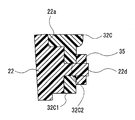
- the mounting structure of the sensor housing 32C to the bumper cover 22 may be configured as shown in FIG. 9B.
- a fastening protrusion 22 d protrudes rearward from the back surface 22 a of the bumper cover 22.
- the fastening protrusion 22d formed on the bumper cover 22 is inserted into the attachment hole 32C2, and the tip of the fastening protrusion 22d protruding from the attachment hole 32C2 (projecting from the attachment hole).
- Fastening plug 35 is fixed to the corresponding part).
- the sensor housing 32 ⁇ / b> C is attached to the bumper cover 22.
- the fastening plug 35 is fixed to the fastening projection 22d by heat welding or the like. Since the other configuration of the sensor unit 3C is the same as that of the sensor unit 3 according to the first embodiment, further description thereof is omitted.
- the sensor housing 32C has the mounting hole 32C2 extending therethrough, and the fastening pin 34 passed through the mounting hole 32C2 is fixed to the bumper cover 22, whereby the sensor housing 32C is mounted on the bumper cover 22. Is attached.
- the fastening protrusion 22d protruding from the back surface 22a of the bumper cover 22 is inserted into the mounting hole 32C2, the fastening plug 35 is fixed to the fastening protrusion 22d protruding from the mounting hole 32C2, and the sensor housing 32C is attached to the bumper cover 22. It is attached.
- the holding force of the sensor unit 3C with respect to the bumper cover 22 can be increased, and the sensor unit 3C is attached to the bumper cover 22 against changes in ambient temperature, submersion of the bumper cover 22, stepping stones from the road surface, and the like. On the other hand, it can be firmly fixed.
- Embodiment 3 Hereinafter, based on FIG. 10, FIG. 11A, and FIG. 11B, the structure of sensor unit 3D by Embodiment 3 is demonstrated.
- the sensor housing 32D (corresponding to the film support) included in the sensor unit 3D is similar to the sensor housing 32B (shown in FIG. 7B) according to the second modification of the first embodiment described above and the first housing piece 33e and the first housing piece 33e.
- the piezoelectric film 31 is sandwiched between the first housing piece 33e and the second housing piece 33d in a state where they are joined to each other. (Shown in FIG. 11A).
- the sensor unit 3D may be formed by integrally forming the piezo film 31 with respect to the sensor housing 32D.
- the sensor housing 32D covers the entire outer peripheral surface of the piezo film 31.
- the sensor housing 32 ⁇ / b> D extends in the vehicle width direction so as to connect both end portions of the bumper cover 22.
- a material similar to that of the sensor housing 32 according to the first embodiment is applied to the sensor housing 32D, which is more rigid than the piezo film 31 and has a predetermined flexibility.
- the sensor housing 32 ⁇ / b> D can be deformed following the shape of the bumper cover 22 when attached to the bumper cover 22. Further, the sensor housing 32 ⁇ / b> D is formed to be deformable together with the bumper cover 22 at the time of collision with the front bumper 21.
- the first housing piece 33e and the second housing piece 33d are collectively referred to as housing pieces 33e and 33d (corresponding to a pair of support pieces). Similar to the sensor housing 32B, the first housing piece 33e (corresponding to one of the support pieces) is a support wall 33e1 that supports one surface of the piezo film 31, and a pair of holding pieces 33e2 (holding) that face the support wall 33e1. Corresponds to the section). Accordingly, the piezoelectric film 31 is held between the holding piece 33e2 and the support wall 33e1 before the first housing piece 33e and the second housing piece 33d are joined.
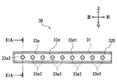
- a plurality of mounting bosses 33e3 project forward from the first housing piece 33e of the sensor housing 32D. As shown in FIG. 10, the plurality of mounting bosses 33e3 are formed so as to be arranged at equal intervals in the vehicle width direction. Each mounting boss 33e3 is formed in a tapered shape (shown in FIG. 11A). As shown in FIG. 11B, each mounting boss 33 e 3 is inserted into a holding hole 22 e formed on the back surface 22 a of the bumper cover 22. Thereby, the sensor housing 32D is attached to the bumper cover 22.
- the holding hole 22e is formed in a shape that matches the outer peripheral surface of the mounting boss 33e3.
- the mounting boss 33e3 is fixed to the holding hole 22e by press fitting, welding, adhesion, or the like.
- the shape, size, and number of the mounting boss 33e3 and the holding hole 22e are not limited to those in the present embodiment, and can be freely set according to the space around the sensor unit 3D, the required holding force for the bumper cover 22, and the like. It is possible. Since the other configuration of the sensor unit 3D is the same as that of the sensor unit 3 according to the first embodiment, further description thereof is omitted.
- the sensor unit 3D can be attached to the bumper cover 22 by inserting the attachment boss 33e3 of the sensor housing 32D into the holding hole 22e of the bumper cover 22. Thereby, there is no need for work such as screw tightening, and the work of attaching the sensor unit 3D to the bumper cover 22 can be simplified.
- the sensor housing 32E (corresponding to the film support) included in the sensor unit 3E is formed by joining the first housing piece 33f and the second housing piece 33d in the same manner as the sensor housing 32D according to Embodiment 3 described above. Has been.
- the piezoelectric film 31 is sandwiched between the first housing piece 33f and the second housing piece 33d in a state of being joined to each other (shown in FIG. 12A).
- the sensor unit 3E may be formed by integrally forming the piezo film 31 with respect to the sensor housing 32E.
- the first housing piece 33f and the second housing piece 33d are collectively referred to as housing pieces 33f and 33d (corresponding to a pair of support pieces).
- the first housing piece 33f (corresponding to one of the support pieces) has a support wall 33f1 and a pair of holding pieces 33f2 (corresponding to the holding portion). .
- a plurality of mounting bosses 33f3 project forward from the first housing piece 33f.
- each mounting boss 33f3 is formed in a substantially tapered shape.
- a retaining rib 33f4 is formed at the tip of the mounting boss 33f3. The retaining rib 33f4 protrudes outward in the radial direction on the circumference of each mounting boss 33f3.
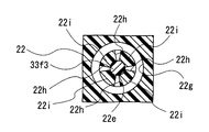
- a holding hole 22e is formed on the back surface 22a of the bumper cover 22, and a hook portion 22f (corresponding to an engaging portion) is formed at the bottom of each holding hole 22e.
- the hook portion 22f is formed such that the inner peripheral surface of the holding hole 22e protrudes outward in the radial direction over the entire periphery.
- an annular circumferential groove 22g having a predetermined depth in the front-rear direction is formed around the holding hole 22e so as to surround the holding hole 22e.
- a plurality of divided slits 22h are provided on the circumference so as to connect both.
- a plurality of engagement pieces 22i are formed on the circumference between the holding hole 22e and the circumferential groove 22g (shown in FIG. 12C).
- the mounting boss 33f3 of the sensor housing 32E When attaching the sensor housing 32E to the bumper cover 22, the mounting boss 33f3 of the sensor housing 32E is inserted into the holding hole 22e of the bumper cover 22. Thereby, all the engagement pieces 22i are pressed radially outward by the retaining ribs 33f4. The engaging piece 22i pressed by the retaining rib 33f4 is bent toward the circumferential groove 22g, and the mounting boss 33f3 smoothly enters the holding hole 22e. When the mounting boss 33f3 further enters the holding hole 22e, the retaining rib 33f4 engages with the hook portion 22f formed in the holding hole 22e in the direction of removal from the holding hole 22e.
- Embodiment 3 The effect of the modification of Embodiment 3 is described.
- the retaining rib 33f4 of the sensor housing 32E extends from the holding hole 22e with respect to the hook portion 22f formed in the holding hole 22e. It is engaged in the direction of pulling out.
- the mounting boss 33f3 can be prevented from falling off the holding hole 22e, and the holding force of the sensor housing 32E with respect to the bumper cover 22 can be increased.
- the engagement piece 22i of the bumper cover 22 is formed to be able to bend toward the circumferential groove 22g.
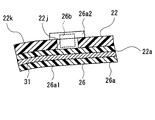
- a clearance sonar 26 is attached to the bumper cover 22.
- the clearance sonar 26 is a device that detects that the bumper cover 22 and the obstacle are approaching each other, and includes a sonar housing 26a (corresponding to a film support) fixed to the bumper cover 22.
- the sonar housing 26a is formed of a synthetic resin material, and includes an extension portion 26a1 extending in the vehicle width direction so as to connect both ends of the bumper cover 22 and a distance measuring sensor 26b, and from the extension portion 26a1 to the front. And a plurality of protruding detection portions 26a2.
- the sonar housing 26a is attached to the back surface 22a of the bumper cover 22 by adhesion, fitting, or the like.
- Each detection unit 26 a 2 passes through a sensor hole 22 j formed in the bumper cover 22 and protrudes from the front surface 22 k of the bumper cover 22.
- the piezo film 31 according to the present embodiment is held in the sonar housing 26a by being incorporated in the extending portion 26a1 of the sonar housing 26a.
- the extending part 26a1 corresponds to a pair of support walls that support both sides of the piezoelectric polymer film.
- the piezo film 31 is integrally formed with the sonar housing 26a by insert molding or the like.
- the sonar housing 26 a covers the entire outer peripheral surface of the piezo film 31.
- the sonar housing 26a is more rigid than the piezo film 31 and has a predetermined flexibility.
- the sonar housing 26 a is formed so as to be deformable together with the bumper cover 22 at the time of collision with the front bumper 21.
- other configurations are the same as those according to the first embodiment, and thus further description thereof is omitted.
- the piezo film 31 is integrally formed with the extending portion 26a1 of the sonar housing 26a. Thereby, it is not necessary to provide a sensor housing other than the sonar housing 26a, and a space on the vehicle VE can be saved and the number of parts can be reduced.
- Embodiment 5 Hereinafter, based on FIG. 14A and FIG. 14B, the structure of the sensor unit 3F by Embodiment 5 is demonstrated.
- a support plate 32F (corresponding to a film support) included in the sensor unit 3F according to the present embodiment is formed in a flat plate shape, and is fitted into a support recess 22m formed on the back surface 22a of the bumper cover 22.
- the support plate 32F extends in the vehicle width direction so as to connect both ends of the bumper cover 22, and is fixed to the bumper cover 22 by adhesion or the like.
- the peripheral edge of the support plate 32 ⁇ / b> F is engaged with the locking claw 22 n of the bumper cover 22, thereby preventing the support plate 32 ⁇ / b> F from falling off the bumper cover 22.
- the peripheral portion of the support plate 32F is fitted into the support recess 22m while bending the locking claw 22n of the bumper cover 22.
- the support plate 32F is made of the same material as that of the sensor housing 32 according to the first embodiment, and is more rigid than the piezo film 31 and has a predetermined flexibility.
- the support plate 32 ⁇ / b> F can be deformed following the shape of the bumper cover 22 when attached to the bumper cover 22. Further, the support plate 32 ⁇ / b> F is formed to be deformable together with the bumper cover 22 at the time of collision with the front bumper 21.
- the piezo film 31 in this embodiment is sandwiched between the back surface 22a of the bumper cover 22 and the front surface 32F1 of the support plate 32F (corresponding to the outer peripheral surface of the film support).
- the front surface 32F1 supports one surface of the piezo film 31 and corresponds to a support wall.
- the support plate 32F and the bumper cover 22 cover the entire outer peripheral surface of the piezo film 31.
- the shape and size of the support plate 32F are not limited to this embodiment, and can be freely set according to the peripheral space of the sensor unit 3F, the shape of the bumper cover 22, and the like. Since the other configuration of the sensor unit 3F is the same as that of the sensor unit 3 according to the first embodiment, further description thereof is omitted.
- the piezo film 31 is sandwiched between the back surface 22a of the bumper cover 22 and the support plate 32F.
- the mold structure for forming the support plate 32F can be simplified.
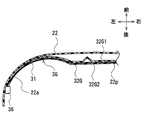
- Embodiment 6 Hereinafter, based on FIG. 15A and FIG. 15B, the structure of the sensor unit 3G by Embodiment 6 is demonstrated. Similar to the sensor unit 3 according to the first embodiment, the sensor unit 3G according to the present embodiment extends in the vehicle width direction so as to connect both ends of the bumper cover 22 (in FIGS. 15A and 15B, Only the left half of the width is shown).
- the sensor unit 3G holds the piezo film 31 by the sensor housing 32G by covering the entire outer peripheral surface of the piezo film 31 with a sensor housing 32G (corresponding to a film support).
- the sensor housing 32G has a pair of support walls 32G1 and 32G2 that support both surfaces of the piezo film 31, respectively.
- the piezo film 31 is integrally formed with the sensor housing 32G by insert molding or the like.
- the sensor housing 32 ⁇ / b> G is formed in a shape that matches the back surface 22 a of the bumper cover 22.
- the sensor housing 32G is made of a hard synthetic resin material so as to be fitted to the back surface 22a of the bumper cover 22, and is formed of a resin material that can be deformed together with the bumper cover 22 when it collides with the front bumper 21.
- the sensor housing 32G is attached to the bumper cover 22 by bonding or fastening pins.
- a sensor interface 36 is connected to an end of the sensor housing 32G in the vehicle width direction. Since the other configuration of the sensor unit 3G is the same as that of the sensor unit 3 according to the first embodiment, further description thereof is omitted.
- the sensor housing 32 ⁇ / b> G is formed in a shape that matches the back surface 22 a of the bumper cover 22. Therefore, even if the back surface 22a of the bumper cover 22 has an uneven portion such as the grill portion 22p (shown in FIG. 15B), the sensor unit 3G can be mounted without deforming the sensor housing 32G according to the shape of the bumper cover 22. It can be easily attached to the bumper cover 22.
- the sensor housing 32 ⁇ / b> H according to this modification is attached to the bumper cover 22 so that at least a part in the vehicle width direction has a predetermined gap ⁇ between the sensor housing 32 ⁇ / b> H and the bumper cover 22. That is, the sensor housing 32H is fixed so as to abut against the back surface 22a of the bumper cover 22 at both end portions in the vehicle width direction (only the left end portion is shown in FIG. 15C). There is a gap ⁇ between 22p.
- the sensitivity of collision detection can be reduced in the vehicle width direction central portion where the deformation amount Q of the bumper cover 22 due to the collision is large.
- the gap ⁇ may be set according to the design of the bumper cover 22. That is, in the bumper cover 22, when a collision occurs at an uneven part or a part formed by a curved surface, since the deformation amount Q tends to be small, the gap ⁇ is set to a small value (including 0) at the part. It may be set. Further, in the bumper cover 22, when a collision occurs in a wide plane part, the deformation amount Q tends to increase. Therefore, the gap ⁇ may be set to a large value in the part. Further, the gap ⁇ may be set in accordance with the rigidity of the bumper cover 22.
- the sensor unit 3J according to the present embodiment is formed by integrally forming a piezo film 31 with respect to a sensor housing 32J (corresponding to a film support) in the same manner as the sensor unit 3 according to the first embodiment (see FIG. 17A). ). The entire outer peripheral surface of the piezo film 31 is covered with a sensor housing 32J.
- the sensor unit 3J according to the present embodiment is not necessarily limited to this, and the sensor housing 32J is formed of a pair of housing pieces that are fitted to each other as in the first modification of the first embodiment. Also good.
- the sensor housing 32J extends in the vehicle width direction so as to connect both ends of the bumper cover 22 (shown in FIG. 16).
- the sensor housing 32J has a pair of support walls 32J1 and 32J2 that support both surfaces of the piezo film 31, respectively.
- the sensor unit 3J has a different thickness of the sensor housing 32J depending on the position in the vehicle width direction. Accordingly, the rigidity of the sensor housing 32J varies depending on the position in the vehicle width direction.
- the sensor housing 32J In the center CR in the vehicle width direction shown in FIG. 16 (hereinafter simply referred to as the center CR), the sensor housing 32J has a thickness D (shown in FIG. 17A).
- the thickness of the sensor housing 32J is formed to be d smaller than D (shown in FIG. 17B).
- the corner portion RH and the corner portion LH are collectively referred to as the corner portions RH and LH.
- the thickness D of the center CR is set to, for example, twice the thickness d of the corner portions RH and LH.
- the sensor housing 32J according to the present embodiment is formed such that the rigidity of the center CR is larger than the rigidity of the corner portions RH and LH, and the rigidity of the center CR is approximately twice the rigidity of the corner portions RH and LH. Is set to
- the pedestrian protection system 1 activates the pedestrian protection device 5 when a pedestrian collides with the vehicle VE, and operates the pedestrian protection device 5 when a small animal collides. Absent. However, as shown in FIG. 18B, when the vehicle VE collides, the center CR has a larger deformation amount of the bumper cover 22 due to the collision than the corner portions RH and LH, and the piezo film voltage Vpz generated by the sensor unit 3J. Tend to be higher. Therefore, it is very difficult to set a certain threshold value Vthc that can distinguish between a collision caused by a pedestrian and a collision caused by a small animal or the like. On the other hand, there is a method of setting a map-type threshold value Vthv (shown in FIG. 18B) having different values depending on the collision position in the vehicle width direction. However, in this case, there is a problem that the pedestrian protection ECU 6 needs to detect the collision position in the vehicle width direction, and a complicated algorithm for collision detection or the like is required.
- the sensor housing 32J according to the present embodiment is formed such that the rigidity of the center CR is larger than that of the corner portions RH and LH. For this reason, as shown in FIG. 18A, when the vehicle VE collides, the center CR and the corner portions RH and LH have the same displacement amount due to the collision, and the piezo film voltage Vpz generated by the sensor unit 3J. The difference between the two has been reduced. Therefore, it is possible to distinguish between a collision caused by a pedestrian and a collision caused by a small animal or the like based on a certain threshold value Vthc.
- the sensor housing 32J is not limited to the center CR having a larger rigidity than the corners RH and LH.
- the rigidity of the sensor housing 32J may be set in accordance with the design of the bumper cover 22. That is, in the bumper cover 22, when a collision occurs at an uneven portion or a portion formed by a curved surface, the deformation amount of the bumper cover 22 tends to be small, so the rigidity of the sensor housing 32 ⁇ / b> J is set to a small value. Also good. Further, in the bumper cover 22, when a collision occurs in a wide plane portion, the deformation amount is likely to increase, and therefore the rigidity of the sensor housing 32J may be set to a large value.
- the rigidity of the sensor housing 32J is set to a small value. Also good.
- the sensor housing 32J of the sensor unit 3J may be formed of a foam material such as slab urethane or molded urethane.
- the foam density of the center CR can be made larger than the foam density of the corner portions RH and LH, and the rigidity of the center CR can be made larger than the stiffness of the corner portions RH and LH.
- the thickness of the center CR may be larger than the thickness of the corner portions RH and LH. Since the other configuration of the sensor unit 3J is the same as that of the sensor unit 3 according to the first embodiment, further description thereof is omitted.
- Embodiment 7 The effect of Embodiment 7 is described.
- the sensor housing 32J since the sensor housing 32J has different rigidity according to the position in the vehicle width direction, the amount of displacement due to the collision is substantially the same regardless of the position in the vehicle width direction where the collision has occurred. can do. For this reason, it is possible to accurately detect a collision by a pedestrian based on a certain threshold value Vthc. In addition, it is possible to accurately detect a collision by a pedestrian based on a certain threshold value Vthc regardless of the position in the vehicle width direction where the collision has occurred.
- the algorithm can be simplified.
- the rigidity of the sensor housing 32J can be varied depending on the position in the vehicle width direction with a simple configuration. Furthermore, the sensor housing 32J can easily vary the rigidity of each position by only changing its mold.
- the sensor unit 3K by the 1st modification of Embodiment 7 is demonstrated. Similar to the sensor unit 3 according to the first embodiment, the sensor unit 3K according to the present embodiment is formed by integrally forming a piezo film 31 with respect to a sensor housing 32K (corresponding to a film support). The entire outer peripheral surface of the piezo film 31 is covered with a sensor housing 32K.
- the sensor housing 32K has a pair of support walls 32K1 and 32K2 that support both surfaces of the piezo film 31, respectively.
- the sensor housing 32K extends in the vehicle width direction so as to connect both end portions of the bumper cover 22.
- the sensor housing 32K has a plurality of ribs 32K3 on the support wall 32K2 (corresponding to at least part of the outer peripheral surface) in the center CR.
- the sensor housing 32K does not have the rib 32K3 at the corner portions RH and LH (shown in FIG. 19B).
- the sensor housing 32K is formed such that the rigidity of the center CR is larger than that of the corner portions RH and LH.
- the sensor housing 32K may include ribs 32K3 on both the center CR and the corner portions RH and LH, and the number of ribs 32K3 on the center CR may be larger than the number of ribs 32K3 on the corner portions RH and LH.
- the sensor housing 32K may be provided with ribs 32K3 on both the center CR and the corner portions RH and LH, and the rib 32K3 of the center CR may be formed larger than the ribs 32K3 of the corner portions RH and LH.
- the sensor housing 32K is provided with ribs 32K3 on both the center CR and the corner portions RH and LH, and the shape of the rib 32K3 of the center CR is larger than the shape of the ribs 32K3 of the corner portions RH and LH. Also good.
- the rib 32K3 according to the present embodiment may be combined with that according to the seventh embodiment described above.
- the thickness of the center CR may be larger than the thickness of the corner portions RH and LH, and the rib 32K3 may be formed only in the center CR. Since the other configuration of the sensor unit 3K is the same as that of the sensor unit 3 according to the first embodiment, further description thereof is omitted.
- the plurality of ribs 32K3 are formed only in the center CR of the sensor housing 32K.
- the rigidity of the center CR can be formed larger than the corner portions RH and LH of the sensor housing 32K with a simple configuration. Further, the rigidity of each position of the sensor housing 32K can be easily changed by changing the mold.
- symbol) by the 2nd modification of Embodiment 7 is demonstrated.
- the sensor unit according to the present embodiment is formed by covering the entire outer peripheral surface of the piezo film 31 with a sensor housing 32L (corresponding to a film support).
- the sensor housing 32L extends in the vehicle width direction so as to connect both end portions of the bumper cover 22.
- the sensor housing 32L according to the present embodiment is formed of a fiber cloth.
- the fiber cloth used for the sensor housing 32K is not limited to these, but, for example, woven cloth or felt such as nylon or polyamide, or other non-woven cloth is applicable.
- the sensor housing 32L is formed such that the thickness of the center CR is larger than the thickness of the corner portions RH and LH, and the rigidity of the center CR is set larger than the rigidity of the corner portions RH and LH. May be. Further, if the sensor housing 32L is formed of a woven fabric, the thickness (denier) of the fibers used for the sensor housing 32L may be varied according to the position in the vehicle width direction. For example, a fiber thicker than the corner portions RH and LH is used for the center CR. Thereby, the rigidity of the center CR is formed larger than the rigidity of the corner portions RH and LH.
- the pattern of the weave may be varied depending on the position in the vehicle width direction.
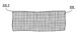
- a pattern of weaving the corner portions RH and LH is a pattern 32L1 (first pattern) woven vertically and horizontally.
- the pattern of the center CR weaving pattern is a pattern 32L2 (second pattern) similarly woven vertically and horizontally, and pattern 2 is denser than pattern 1,
- the rigidity may be larger than the rigidity of the corner portions RH and LH.
- the sensor 20C by using a weaving pattern 32L3 (third pattern) woven in an oblique direction in a part of the sensor housing 32L, the sensor can be adjusted in accordance with the position in the vehicle width direction.
- the rigidity of the housing 32L may be varied.
- the sensor housing 32L includes a fiber cloth, and the thickness of the fibers used in the fiber cloth or the pattern of the weave differs depending on the position in the vehicle width direction. Thereby, the rigidity of each position of the sensor housing 32L can be easily changed with a simple configuration.
- a plurality of sensor units 3 may be mounted on the bumper cover 22 so as to be aligned in the vehicle width direction or the vertical direction. Further, the entire outer peripheral surface of the piezo film 31 is not necessarily covered by the sensor housing 32. If supported by the sensor housing 32, a part of the outer peripheral surface of the piezo film 31 may be exposed from the sensor housing 32. In the sensor unit 3J according to the seventh embodiment, the rigidity of each position may be changed by changing the material of the sensor housing 32J according to the position in the vehicle width direction.
Landscapes
- Engineering & Computer Science (AREA)
- Mechanical Engineering (AREA)
- Force Measurement Appropriate To Specific Purposes (AREA)
Abstract
車両用衝突検知装置(1)は、圧電性高分子フィルム(31)と、フィルムよりも剛性を有し、フィルムの少なくとも一面を支持する支持壁(32a、32b、32C3、32C4、32G1、32G2、32J1、32J2、32K1、32K2、33a1、33b1、33c1、33d1、33e1、33f1、26a1、32F1)を含み、車両(VE)の前方部(21)に設けられたバンパーカバー(22)の内側面(22a)に取り付けられており、バンパーカバーとともに変形可能なフィルム支持体(32、32A、32B、32C、32D、32E、32F、32G、32H、32J、32K、32L、26a)と、バンパーカバーの変形量(Q)に応じて、フィルムによって発生された所定の出力電圧(Vpz)に基づいて、バンパーカバーに、衝突物を保護する保護装置(5)の作動を必要とする衝突が発生したことを検出する衝突判定部(62)と、を備える。
Description
本出願は、2015年7月28日に出願された日本特許出願番号2015-148968号と、2016年2月15日に出願された日本特許出願番号2016-26237号に基づくもので、ここにその記載内容を援用する。
本開示は、車両への歩行者等の衝突を検出する車両用衝突検知装置に関する。
バンパーカバーの後方に緩衝体を設け、緩衝体とクロスメンバーとの間に検出用チューブを配置し、車両前端部への歩行者の衝突を検知する車両用衝突検知装置に関する従来技術があった(例えば、特許文献1参照)。当該従来技術による衝突検知装置は、バンパーカバーにおける広範囲の部位に対する衝突の検知を可能にすることを意図したものである。この従来技術においては、車幅方向に長く延びた検出用チューブ内に閾値以上の圧力が発生した場合に、バンパーカバーへの歩行者の衝突が発生したことを検知している。
しかしながら、当該車両用衝突検知装置においては、車両前端部への衝突を、緩衝体を介して検知しているため、車両前端部のバンパーカバーにおいて衝突が発生した場合、当該衝突による衝撃は緩衝体に伝播する間に減衰する。このため、例えば、衝突による衝撃が小さい場合、緩衝体の後方に配置された検出用チューブでは、衝突の衝撃による圧力の上昇を精度よく検知することはできなかった。また、上述した従来技術による車両用衝突検知装置においては、検出用チューブを緩衝体から脱落させることなく、車幅方向に延びるように配置する必要があり、組付け作業の効率化の阻害要因となっていた。
本開示は上記事情に鑑みてなされたものであり、その目的は、車両への衝突が発生したことを精度よく検出することができる組付けが容易な車両用衝突検知装置を提供することにある。
上述した目的を達成するために、本開示の1つの態様に係る車両用衝突検知装置は、変形することにより、所定の出力電圧を発生する圧電性高分子フィルムと、圧電性高分子フィルムよりも剛性を有し、圧電性高分子フィルムの少なくとも一面を支持する支持壁を含み、車両の前方部に設けられたバンパーカバーの内側面に取り付けられており、バンパーカバーとともに変形可能なフィルム支持体と、バンパーカバーの変形量に応じて、圧電性高分子フィルムによって発生された出力電圧に基づいて、バンパーカバーに、衝突物を保護する保護装置の作動を必要とする衝突が発生したことを検出する衝突判定部と、を備えている。
この構成によれば、バンパーカバーの変形量に応じた出力電圧を発生する圧電性高分子フィルムを備えている。そして、衝突判定部は、圧電性高分子フィルムによって形成された出力電圧に基づいて、車両のバンパーカバーに衝突が発生したことを検出している。これにより、バンパーカバーの変形量が直接的に影響する出力電圧に基づいて、車両のバンパーカバーに衝突が発生したことを正確に検出することができる。また、より剛性を有したフィルム支持体によって圧電性高分子フィルムを支持させ、当該フィルム支持体をバンパーカバーに取り付けている。このため、薄膜状の圧電性高分子フィルムの車両への組付けが容易になり、製造の容易な車両用衝突検知装置にすることができる。尚、本開示による車両用衝突検知装置は、歩行者衝突のみの検知を対象としているのではなく、歩行者保護装置を作動させる必要のあるすべての衝突検知を対象としている。
本開示についての上記目的およびその他の目的、特徴や利点は、添付の図面を参照しながら下記の詳細な記述により、より明確になる。その図面は、
実施形態1による歩行者保護システムが取り付けられた車両の平面図
図1のII-II断面図
実施形態1によるセンサユニットの後方視を示した図
実施形態1による歩行者保護システムの構成を示したブロック図
実施形態1による歩行者保護システムの制御フローチャートを示した図
実施形態1の第1変形例によるセンサユニットの分解断面図
図6Aに示したセンサユニットの組付けた状態を表した断面図
実施形態1の第2変形例によるセンサユニットの分解断面図
図7Aに示したセンサユニットの組付けた状態を表した断面図
実施形態2による車両の前方部を前後方向にカットした場合の断面図
図8に示したセンサユニットの後方視を表した図
図8のIXB部に示した締結部について、異なる締結方法を表した拡大断面図
実施形態3によるセンサユニットの後方視を表した図
図10のXIA-XIA断面図
図11Aに示したセンサユニットを、バンパーカバーに取り付けた状態を表した断面図
実施形態3の変形例によるセンサユニットを、前後方向にカットした場合の断面図
図12Aに示したセンサユニットを、バンパーカバーに取り付けた状態を表した断面図
図12BのXIIC-XIIC断面図
実施形態4によるクリアランスソナーを、バンパーカバーに取り付けた状態を水平方向にカットした場合の断面図
図13AのXIIIB部を表した拡大断面図
実施形態5によるセンサユニットの分解断面図
図14Aに示したセンサユニットの組付けた状態を表した断面図
実施形態6によるセンサユニットを水平方向にカットした場合の断面図
図15Aに示したセンサユニットを、バンパーカバーに取り付けた状態を表した断面図
実施形態6の変形例によるセンサユニットを、バンパーカバーに取り付けた状態を表した断面図
実施形態7によるセンサユニットの平面図
図16のXVIIA-XVIIA断面図
図16のXVIIB-XVIIB断面図
実施形態7によるセンサユニットの出力特性を表したグラフを示した図
比較例としてのセンサユニットの出力特性を表したグラフを示した図
実施形態7の第1変形例によるセンサユニットを、図16に示したセンターにおいて車幅方向に対して垂直にカットした場合の断面図
実施形態7の第1変形例によるセンサユニットを、図16に示したコーナー部においてカットした場合の断面図
実施形態7の第2変形例によるセンサハウジングにおいて、第1パターンによる外周面の一部を示した模式図
実施形態7の第2変形例によるセンサハウジングの第2パターンによる外周面の一部を示した模式図
実施形態7の第2変形例によるセンサハウジングの第3パターンによる外周面の一部を示した模式図
以下、実施形態1乃至実施形態7について説明する。尚、説明中および図1乃至図19B中における方向を示す記載は、車両VEに着座した運転者にとっての方向と一致するものとする。例えば、図1乃至図19B中において、「前」という表示は、矢印の方向が車両VEの前方に該当していることを示している。また、以下、車両VEに対する歩行者の衝突を中心に説明しているが、本開示による車両用衝突検知装置は、歩行者衝突の検知のみを対象としているのではなく、自転車、ベビーカーといった歩行者保護装置5を作動させる必要のあるすべての衝突検知を対象としている。
(実施形態1)
図1乃至図5に基づき、実施形態1による歩行者保護システム1(車両用衝突検知装置に該当する)について説明する。歩行者保護システムの全体構成について以下に述べる。図1に示したように、車両VEの前端部には、フロントバンパー21(車両の前方部に該当する)が取り付けられている。フロントバンパー21は左右方向に延びており、バンパーカバー22とバンパーアブソーバー23とを含んでいる。バンパーカバー22は、合成樹脂材料にて形成されており、車両VEの前方部における意匠面を成している。バンパーアブソーバー23は、フロントバンパー21において衝突が発生した場合の衝撃吸収材として、バンパーカバー22の後方に設けられている。バンパーアブソーバー23は、例えば、発泡ポリプロピレンのような発泡樹脂によって形成されている。
(実施形態1)
図1乃至図5に基づき、実施形態1による歩行者保護システム1(車両用衝突検知装置に該当する)について説明する。歩行者保護システムの全体構成について以下に述べる。図1に示したように、車両VEの前端部には、フロントバンパー21(車両の前方部に該当する)が取り付けられている。フロントバンパー21は左右方向に延びており、バンパーカバー22とバンパーアブソーバー23とを含んでいる。バンパーカバー22は、合成樹脂材料にて形成されており、車両VEの前方部における意匠面を成している。バンパーアブソーバー23は、フロントバンパー21において衝突が発生した場合の衝撃吸収材として、バンパーカバー22の後方に設けられている。バンパーアブソーバー23は、例えば、発泡ポリプロピレンのような発泡樹脂によって形成されている。
バンパーアブソーバー23は、その後端面23aにおいてバンパーリインフォースメント24の前面24aに取り付けられている。バンパーリインフォースメント24は、アルミニウム合金のような金属材料によって、内部が中空に形成された強度部材であって左右方向に延びている。バンパーリインフォースメント24は、前後方向に延びた左右一対のサイドメンバ25R、25Lの前端部に固定されている。上述したフロントバンパー21、バンパーリインフォースメント24およびサイドメンバ25R、25Lによって、ボデーユニット2が形成されている。
図1および図2に示したように、バンパーカバー22の後面である裏面22a(バンパーカバーの内側面に該当する)には、センサユニット3が取り付けられている。センサユニット3は、車両VE上において、歩行者等が衝突する高さに取り付けられてもよい。図2および図3に示したように、センサユニット3は、ピエゾフィルム31(圧電性高分子フィルムに該当する)の全外周面が、センサハウジング32(フィルム支持体に該当する)によって覆われることにより形成されている。ピエゾフィルム31は、インサート成形等により、センサハウジング32に対し一体成形されている。センサユニット3は、バンパーカバー22の両端部をつなぐように、車幅方向(横方向)に延在している(図1示)。
センサユニット3に含まれたピエゾフィルム31は、薄膜状に形成されたピエゾ素子を、金属皮膜による一対の電極(図示せず)によって挟むことにより形成されている。ピエゾ素子は、ポリフッ化ビニリデン(PVDF)、ポリペプチド、ポリ乳酸、ポリメチルグルタメート、ポリベンジルグルタメートといった圧電性高分子材料により形成されている。衝突によりバンパーカバー22が変形すると、ピエゾフィルム31には、変形によって引っ張り応力または圧縮応力が加わり、電極間において、バンパーカバー22の変形量Qに応じた所定の出力電圧(以下、ピエゾフィルム電圧Vpzと言う)を発生させる。ピエゾフィルム自体は公知であり、例えば、公開特許公報である特開2004-96980号公報、特開2007-212436号公報および特開2013-29368号公報等に開示されている。ピエゾフィルム3に代えて、焦電体(パイロ)フィルムをセンサハウジング32で覆って、センサユニット3を形成してもよい。
センサハウジング32は、ポリプロピレン(Polypropylene)、ポリエチレン(Polyethylene)、エラストマー(Elastomer)、EPDM(Ethylene Propylene Diene Monomer)、シリコンゴム等の合成樹脂材料または合成ゴム材料により形成されている。センサハウジング32は、ピエゾフィルム31よりも剛性を有するとともに、所定の柔軟性を備えている。センサハウジング32は、ピエゾフィルム31の両面をそれぞれ支持する一対の支持壁32a、32bを有している。センサハウジング32は、ピエゾフィルム31を支持した状態で、バンパーカバー22に接着剤等によって固定されている。また、センサハウジング32は、バンパーカバー22への取り付け時に、バンパーカバー22の形状に倣って変形することが可能である。さらに、センサハウジング32は、フロントバンパー21への衝突時に、バンパーカバー22とともに変形可能に形成されている。センサハウジング32は、所定の剛性および変形可能性を満足することができるのであれば、上記列挙した材質以外によって形成されていてもよい。
図1に戻って、車両VEに設けられた速度センサ4は、車両VEの車輪またはトランスミッション等に取り付けられ、車両VEの走行速度を検出している。カウルエアバッグ装置51は、歩行者保護装置5(保護装置に該当する)に含まれている。カウルエアバッグ装置51は、フロントバンパー21に歩行者が衝突した際に、図1に示したエンジンフードHE上からフロントウィンドウWF下部にかけてバッグを展開させ、衝突した歩行者等の衝突物を保護する。また、ポップアップフード52も、歩行者保護装置5に含まれている。ポップアップフード52は、フロントバンパー21に歩行者等が衝突した際に、エンジンフードHEの後端を上昇させている。これによって、エンジンフードHEが緩衝部材となって、歩行者がエンジンなどの剛性を有した部材に衝突することを防ぎ、衝突した歩行者等の衝突物を保護する。
歩行者保護ECUの構成について述べる。車両VEにおいて、図示しない運転席前側のフロアトンネル上には、歩行者保護ECU6が取り付けられている。歩行者保護ECU6は、図示しない入出力装置、CPU、RAM等により形成された制御装置である。図1に示したように、歩行者保護ECU6には、上述したピエゾフィルム31、速度センサ4、カウルエアバッグ装置51およびポップアップフード52が、通信線によって接続されている。
図4に示したように、歩行者保護ECU6は、車速判定部61、衝突判定部62、AND回路63および保護装置ドライバー64を含んでいる。車速判定部61は、速度センサ4に接続されている。車速判定部61は、速度センサ4による車速検出値Sdetが、所定の第1車速閾値Sth1以上であり、かつ、所定の第2車速閾値Sth2以下であるか否かを判定する。車速判定部61は、車速検出値Sdetが、第1車速閾値Sth1以上であり、かつ、第2車速閾値Sth2以下である場合に、ハイ(H)信号を出力する。衝突判定部62は、ピエゾフィルム31に接続されている。衝突判定部62は、ピエゾフィルム31から入力されたピエゾフィルム電圧Vpzを、所定の電圧閾値Vthと比較する。衝突判定部62は、ピエゾフィルム電圧Vpzが電圧閾値Vth以上の場合、バンパーカバー22に歩行者保護装置5の作動を必要とする衝突が発生したことを検出し、H信号を出力する。また、演算処理上の理由によって、ピエゾフィルム電圧Vpzに基づいて所定の検出電圧を形成し、検出電圧が電圧閾値Vth以上である場合に、衝突判定部62において、歩行者保護装置5の作動を必要とする衝突が発生したと判定してもよい。AND回路63の一対の入力端は、車速判定部61および衝突判定部62に接続されている。AND回路63は、車速判定部61においてH信号が出力されており、さらに、衝突判定部62においてH信号を出力している場合に、H信号を出力する。保護装置ドライバー64は、AND回路63の出力端に接続されており、AND回路63からH信号が出力されている場合に、カウルエアバッグ装置51またはポップアップフード52を作動させる。
歩行者保護システムの制御方法について述べる。以下、図5に基づいて、歩行者保護ECU6による、歩行者保護システム1の制御方法について説明する。最初に、速度センサ4から車速判定部61に対し、車両VEの車速検出値Sdetが入力される(ステップS101)。次に、車速判定部61によって、車速検出値Sdetが、第1車速閾値Sth1以上であり、かつ、第2車速閾値Sth2以下であるか否かが判定される(ステップS102)。車速検出値Sdetが、第1車速閾値Sth1未満、または、第2車速閾値Sth2を越えていると判定された場合、本制御フローを終了する。車速検出値Sdetが、第1車速閾値Sth1以上であり、かつ、第2車速閾値Sth2以下であると判定された場合、ピエゾフィルム31から衝突判定部62に向けて、ピエゾフィルム電圧Vpzが入力される(ステップS103)。
衝突判定部62に入力されたピエゾフィルム電圧Vpzは、電圧閾値Vth以上であるか否かが判定される(ステップS104)。電圧閾値Vthは、バンパーカバー22に歩行者または自転車が衝突した場合に発生するピエゾフィルム電圧Vpzと、地上工作物が衝突した場合に発生するピエゾフィルム電圧Vpzとの間に設定されている。ピエゾフィルム電圧Vpzが、電圧閾値Vth以上であると判定された場合、バンパーカバー22において、歩行者保護装置5の作動を必要とする衝突が発生したことを検出し(ステップS105)、歩行者保護装置5を作動させる(ステップS106)。ステップS104において、ピエゾフィルム電圧Vpzが、電圧閾値Vth未満であると判定された場合、本制御フローを終了する。
実施形態1の作用効果について述べる。本実施形態によれば、バンパーカバー22の変形量Qに応じたピエゾフィルム電圧Vpzを発生するピエゾフィルム31を備えている。そして、衝突判定部62は、ピエゾフィルム31によって形成されたピエゾフィルム電圧Vpzに基づいて、車両VEのバンパーカバー22に衝突が発生したことを検出している。これにより、バンパーカバー22の変形量Qが直接的に影響するピエゾフィルム電圧Vpzに基づいて、車両VEのバンパーカバー22に衝突が発生したことを正確に検出することができる。また、バンパーアブソーバー23中に、圧力検出用のチューブを設ける必要がなく、製造の容易な歩行者保護システム1にすることができる。
また、ピエゾフィルム31は、薄膜センサであることから、自重だけで大きく変形し、取り扱いが困難であるという問題がある。さらに、薄膜であるために、バンパーカバー22への取り付け時に、ボルト、クリップ等の締結部材を保持する強度が確保できないという課題もある。これに対して、本実施形態においては、より剛性を有したセンサハウジング32によってピエゾフィルム31を支持している。このため、薄膜状のピエゾフィルム31の運搬、車両VEへの取り付け時等の取扱性が向上し、ピエゾフィルム31をバンパーカバー22に容易に取り付けることができる。また、ピエゾフィルム31を支持したセンサハウジング32を、バンパーカバー22に取り付けていることにより、取り付けのためのボルト等を保持する十分な強度を確保することができる。さらに、取付作業時におけるピエゾフィルム31の破損を防止することができ、歩行者保護システム1の信頼性を増大させることができる。
また、ピエゾフィルム31は、センサハウジング32に対して、一体成形されていることにより、センサハウジング32の成形工程とセンサユニット3の組付工程とを一体化でき、センサユニット3を容易に形成することができる。また、センサハウジング32は、ピエゾフィルム31の両面をそれぞれ支持する支持壁32a、32bを有している。これにより、取付作業時におけるピエゾフィルム31の破損を防止することができ、車両VEへの取付け作業性を向上させることができる。また、ピエゾフィルム31の全外周面が、センサハウジング32によって覆われていることにより、ピエゾフィルム31に対する防水性、絶縁性および防塵性を向上させることができる。また、センサハウジング32は、バンパーカバー22への取り付け時に、バンパーカバー22の形状に倣って変形することが可能に形成されている。これにより、バンパーカバー22の裏面22aの形状に拘らず、センサハウジング32とバンパーカバー22との間の密着性を確保することができ、バンパーカバー22によるセンサハウジング32の保持力を増大させることができる。
実施形態1の第1変形例の構成について述べる。以下、図6Aおよび図6Bに基づいて、実施形態1の第1変形例によるセンサユニット3Aについて説明する。本実施形態において、センサユニット3Aに含まれたセンサハウジング32A(フィルム支持体に該当する)は、互いに嵌合する一対の第1ハウジングピース33aと第2ハウジングピース33bとから形成されている。以下、第1ハウジングピース33aと第2ハウジングピース33bとを包括して、ハウジングピース33a、33b(一対の支持ピースに該当する)と言う。ハウジングピース33a、33bは、それぞれ別々に成形されており、ハウジングピース33a、33b同士(支持ピース同士に該当する)の間には、ピエゾフィルム31が介装されている。ハウジングピース33a、33bは、ピエゾフィルム31の両面をそれぞれ支持する支持壁33a1、33b1を有している。ハウジングピース33a、33bは、ピエゾフィルム31を間に挟んだ状態で、圧入、嵌合、スナップフィット、接着、溶着等によって互いに結合されており、ピエゾフィルム31の全外周面を覆っている(図6B示)。センサユニット3Aのその他の構成については、実施形態1によるセンサユニット3と同様であるため、これ以上の説明は省略する。
第1変形例の作用効果について述べる。本変形例によれば、センサハウジング32Aは、互いに接合される一対のハウジングピース33a、33bにより形成され、ピエゾフィルム31は、ハウジングピース33a、33b同士の間に介装されている。これにより、ピエゾフィルム31とハウジングピース33a、33bとを一体成形することなく、センサユニット3Aを形成することができる。このため、ハウジングピース33a、33bを形成するための型構造を、簡素なものにすることができる。
実施形態1の第2変形例の構成について述べる。以下、図7Aおよび図7Bに基づいて、実施形態1の第2変形例によるセンサユニット3Bについて説明する。センサユニット3Bに含まれたセンサハウジング32B(フィルム支持体に該当する)は、第1変形例によるセンサユニット3Aと同様に、第1ハウジングピース33cと第2ハウジングピース33dとを接合することにより形成されている。第1ハウジングピース33cと第2ハウジングピース33dとの間には、ピエゾフィルム31が挟持されており、センサハウジング32Bはピエゾフィルム31の全外周面を覆っている(図7B示)。以下、第1ハウジングピース33cと第2ハウジングピース33dとを包括して、ハウジングピース33c、33d(一対の支持ピースに該当する)と言う。
第1ハウジングピース33c(支持ピースのうちの一方に該当する)は、ピエゾフィルム31の一面を支持する支持壁33c1を有している。また、センサユニット3Aとは異なり、第1ハウジングピース33cは、支持壁33c1に対向するように形成された、上下一対の保持片33c2(保持部に該当する)を有している。各々の保持片33c2は、支持壁33c1とともにピエゾフィルム31を挟持している。ピエゾフィルム31は薄膜により形成されており柔軟性を有するため、保持片33c2と支持壁33c1との間に、周縁部からピエゾフィルム31を挿入し、双方によって保持させることが可能である。保持片33c2の形状、大きさ、第1ハウジングピース33cにおいて設けられる数は、本変形例に限られるものではなく、必要とされるピエゾフィルム31の保持力等に応じて自由に設定することが可能である。一方、第2ハウジングピース33dは、ピエゾフィルム31の他の一面を支持する支持壁33d1を有している。センサユニット3Bのその他の構成については、実施形態1によるセンサユニット3と同様であるため、これ以上の説明は省略する。
実施形態1の第2変形例の作用効果について述べる。本変形例によれば、第1ハウジングピース33cは、ピエゾフィルム31の一面に当接する支持壁33c1と、支持壁33c1に対向するように形成され、支持壁33c1とともにピエゾフィルム31を挟持する保持片33c2とを有している。これにより、ハウジングピース33c、33d同士を接合する前に、第1ハウジングピース33cのみによってピエゾフィルム31を保持することができる。したがって、第1ハウジングピース33cと、第2ハウジングピース33dとの接合時の作業性を向上させることができる。
(実施形態2)
以下、図8、図9Aおよび図9Bに基づいて、実施形態2によるセンサユニット3Cの構成について説明する。本実施形態によるセンサユニット3Cは、実施形態1によるセンサユニット3と同様に、ピエゾフィルム31が、センサハウジング32C(フィルム支持体に該当する)に対し一体成形されて形成されている(図8示)。ピエゾフィルム31の全外周面は、センサハウジング32Cによって覆われている。センサハウジング32Cは、バンパーカバー22の両端部をつなぐように、車幅方向に延在している。センサハウジング32Cは、ピエゾフィルム31の両面をそれぞれ支持する一対の支持壁32C3、32C4を有している。センサハウジング32Cには、実施形態1によるセンサハウジング32と同様の材質が適用されており、ピエゾフィルム31よりも剛性を有するとともに、所定の柔軟性を備えている。また、センサハウジング32Cは、バンパーカバー22への取り付け時に、バンパーカバー22の形状に倣って変形することが可能である。さらに、センサハウジング32Cは、フロントバンパー21への衝突時に、バンパーカバー22とともに変形可能に形成されている。
(実施形態2)
以下、図8、図9Aおよび図9Bに基づいて、実施形態2によるセンサユニット3Cの構成について説明する。本実施形態によるセンサユニット3Cは、実施形態1によるセンサユニット3と同様に、ピエゾフィルム31が、センサハウジング32C(フィルム支持体に該当する)に対し一体成形されて形成されている(図8示)。ピエゾフィルム31の全外周面は、センサハウジング32Cによって覆われている。センサハウジング32Cは、バンパーカバー22の両端部をつなぐように、車幅方向に延在している。センサハウジング32Cは、ピエゾフィルム31の両面をそれぞれ支持する一対の支持壁32C3、32C4を有している。センサハウジング32Cには、実施形態1によるセンサハウジング32と同様の材質が適用されており、ピエゾフィルム31よりも剛性を有するとともに、所定の柔軟性を備えている。また、センサハウジング32Cは、バンパーカバー22への取り付け時に、バンパーカバー22の形状に倣って変形することが可能である。さらに、センサハウジング32Cは、フロントバンパー21への衝突時に、バンパーカバー22とともに変形可能に形成されている。
図9Aに示したように、センサハウジング32Cの上端部には、上方に突出した複数の固定片32C1が形成されている。固定片32C1は、均等間隔で車幅方向に並ぶように形成されている。また、センサハウジング32Cの下端部においても、複数の固定片32C1が下方に突出し、固定片32C1は、車幅方向に均等間隔に形成されている。センサハウジング32Cの上端部および下端部に形成された各々の固定片32C1には、取付孔32C2が貫通している。各々の取付孔32C2は、車幅方向に延びた長穴に形成されている。
図8に示したように、バンパーカバー22の裏面22aには、凹部22bが形成されており、上述したセンサユニット3Cの周縁部が嵌合している。センサハウジング32Cの固定片32C1に形成された取付孔32C2には、それぞれ締結ピン34(締結部材に該当する)が挿入されている。締結ピン34は、合成樹脂材料または金属により形成されている。取付孔32C2に貫通した締結ピン34は、バンパーカバー22の裏面22aに形成された固定孔22cに対し、圧入、溶着または螺子止め等によって固定されている。これにより、センサハウジング32Cは、バンパーカバー22に取り付けられている。上述したように、各々の取付孔32C2は、車幅方向に延びた長穴に形成されている。このため、センサハウジング32Cをバンパーカバー22に取り付ける際に、バンパーカバー22の固定孔22cと、センサハウジング32Cの取付孔32C2との間における車幅方向の位置のばらつきを、長穴によって吸収することが可能に形成されている。固定片32C1および取付孔32C2の形状、大きさ、数は、本実施形態に限られるものではなく、センサユニット3Cの周辺スペース、必要とするバンパーカバー22に対する保持力等に応じて自由に設定することが可能である。
センサハウジング32Cのバンパーカバー22への取付構造は、図9Bに示したもののように構成してもよい。図9Bにおいては、バンパーカバー22の裏面22aから、後方に向けて締結突部22dが突出している。センサハウジング32Cのバンパーカバー22への取り付け時において、バンパーカバー22に形成された締結突部22dを取付孔32C2に挿入し、取付孔32C2から突出した締結突部22dの先端部(取付孔から突出した部位に該当する)に締結栓35を固着させている。これにより、センサハウジング32Cは、バンパーカバー22に取り付けられている。締結栓35は、熱溶着等によって、締結突部22dに固着されている。センサユニット3Cのその他の構成については、実施形態1によるセンサユニット3と同様であるため、これ以上の説明は省略する。
実施形態2の作用効果について述べる。本実施形態によれば、センサハウジング32Cには、取付孔32C2が貫通しており、取付孔32C2に貫通させた締結ピン34をバンパーカバー22に固定することにより、センサハウジング32Cは、バンパーカバー22に取り付けられている。あるいは、バンパーカバー22の裏面22aから突出した締結突部22dを取付孔32C2に挿入し、取付孔32C2から突出した締結突部22dに締結栓35を固着させて、センサハウジング32Cをバンパーカバー22に取り付けている。これらにより、センサユニット3Cの、バンパーカバー22に対する保持力を増大させることができ、周辺温度の変化、バンパーカバー22の水没、路面からの飛び石等に抗して、センサユニット3Cをバンパーカバー22に対して強固に固定することができる。
(実施形態3)
以下、図10、図11Aおよび図11Bに基づいて、実施形態3によるセンサユニット3Dの構成について説明する。センサユニット3Dに含まれたセンサハウジング32D(フィルム支持体に該当する)は、上述した実施形態1の第2変形例によるセンサハウジング32B(図7B示)と同様に、第1ハウジングピース33eと第2ハウジングピース33dとが接合されて形成されている。また、互いに接合された状態において、第1ハウジングピース33eと第2ハウジングピース33dとの間には、ピエゾフィルム31が挟まれている。(図11A示)。センサユニット3Dは、実施形態1によるセンサユニット3と同様に、ピエゾフィルム31が、センサハウジング32Dに対し一体成形されて形成されていてもよい。
(実施形態3)
以下、図10、図11Aおよび図11Bに基づいて、実施形態3によるセンサユニット3Dの構成について説明する。センサユニット3Dに含まれたセンサハウジング32D(フィルム支持体に該当する)は、上述した実施形態1の第2変形例によるセンサハウジング32B(図7B示)と同様に、第1ハウジングピース33eと第2ハウジングピース33dとが接合されて形成されている。また、互いに接合された状態において、第1ハウジングピース33eと第2ハウジングピース33dとの間には、ピエゾフィルム31が挟まれている。(図11A示)。センサユニット3Dは、実施形態1によるセンサユニット3と同様に、ピエゾフィルム31が、センサハウジング32Dに対し一体成形されて形成されていてもよい。
センサハウジング32Dは、ピエゾフィルム31の全外周面を覆っている。センサハウジング32Dは、バンパーカバー22の両端部をつなぐように、車幅方向に延在している。センサハウジング32Dには、実施形態1によるセンサハウジング32と同様の材質が適用されており、ピエゾフィルム31よりも剛性を有するとともに、所定の柔軟性を備えている。また、センサハウジング32Dは、バンパーカバー22への取り付け時に、バンパーカバー22の形状に倣って変形することが可能である。さらに、センサハウジング32Dは、フロントバンパー21への衝突時に、バンパーカバー22とともに変形可能に形成されている。以下、第1ハウジングピース33eと第2ハウジングピース33dとを包括して、ハウジングピース33e、33d(一対の支持ピースに該当する)と言う。センサハウジング32Bと同様に、第1ハウジングピース33e(支持ピースのうちの一方に該当する)は、ピエゾフィルム31の一面を支持する支持壁33e1および支持壁33e1に対向した一対の保持片33e2(保持部に該当する)を有している。これにより、第1ハウジングピース33eと第2ハウジングピース33dとの接合以前において、保持片33e2と支持壁33e1とによって、ピエゾフィルム31が挟持されている。
センサハウジング32Dの第1ハウジングピース33eからは、前方に向けて複数の取付ボス33e3が突出している。図10に示したように、複数の取付ボス33e3は、車幅方向に均等間隔で並ぶように形成されている。各々の取付ボス33e3は、テーパー状に形成されている(図11A示)。図11Bに示したように、それぞれの取付ボス33e3は、バンパーカバー22の裏面22aに形成された保持孔22eに挿入されている。これにより、センサハウジング32Dは、バンパーカバー22に取り付けられている。保持孔22eは、取付ボス33e3の外周面と合致する形状に形成されている。取付ボス33e3は、保持孔22eに対して、圧入、溶着、接着等によって固定されている。取付ボス33e3および保持孔22eの形状、大きさ、数は、本実施形態に限られるものではなく、センサユニット3Dの周辺スペース、必要とするバンパーカバー22に対する保持力等に応じて自由に設定することが可能である。センサユニット3Dのその他の構成については、実施形態1によるセンサユニット3と同様であるため、これ以上の説明は省略する。
実施形態3の作用効果について述べる。本実施形態によれば、センサハウジング32Dの取付ボス33e3を、バンパーカバー22の保持孔22eに挿入することにより、センサユニット3Dをバンパーカバー22に取り付けることができる。これにより、螺子締め等の作業の必要がなく、センサユニット3Dのバンパーカバー22への取付作業を簡素化することができる。
実施形態3の変形例の構成について述べる。以下、図12A、図12Bおよび図12Cに基づいて、実施形態3の変形例によるセンサユニット3Eについて説明する。センサユニット3Eに含まれたセンサハウジング32E(フィルム支持体に該当する)は、上述した実施形態3によるセンサハウジング32Dと同様に、第1ハウジングピース33fと第2ハウジングピース33dとが接合されて形成されている。また、互いに接合された状態において、第1ハウジングピース33fと第2ハウジングピース33dとの間には、ピエゾフィルム31が挟まれている(図12A示)。センサユニット3Eは、実施形態1によるセンサユニット3と同様に、ピエゾフィルム31が、センサハウジング32Eに対し一体成形されて形成されていてもよい。以下、第1ハウジングピース33fと第2ハウジングピース33dとを包括して、ハウジングピース33f、33d(一対の支持ピースに該当する)と言う。
実施形態3によるセンサハウジング32Dと同様に、第1ハウジングピース33f(支持ピースのうちの一方に該当する)は、支持壁33f1と一対の保持片33f2(保持部に該当する)を有している。また、センサハウジング32Dと同様に、第1ハウジングピース33fからは、前方に向けて複数の取付ボス33f3が突出している。また、センサハウジング32Dと同様に、各々の取付ボス33f3は略テーパー状に形成されている。その一方、センサハウジング32Dとは異なり、取付ボス33f3の先端部には抜止リブ33f4が形成されている。抜止リブ33f4は、それぞれの取付ボス33f3の円周上において、半径方向外方に突出している。
図12Bに示したように、バンパーカバー22の裏面22aには、保持孔22eが形成され、各々の保持孔22eの底部にはフック部22f(係合部に該当する)が形成されている。フック部22fは、保持孔22eの内周面が、全周に亘って半径方向外方に突き出るように形成されている。また、保持孔22eの周囲には、保持孔22eを取り囲むように、前後方向に所定の深さを有した円環状の円周溝22gが形成されている。さらに、保持孔22eと円周溝22gとの間には、双方を連結するように、円周上に複数の分割スリット22hが設けられている。これにより、保持孔22eと円周溝22gとの間には、円周上に複数の係合片22iが形成されている(図12C示)。
センサハウジング32Eを、バンパーカバー22に取り付ける場合、センサハウジング32Eの取付ボス33f3を、バンパーカバー22の保持孔22eに挿入する。これにより、すべての係合片22iは、抜止リブ33f4によって半径方向外方に押圧される。抜止リブ33f4によって押圧された係合片22iは、円周溝22g側へ撓まされ、取付ボス33f3は保持孔22e内にスムーズに進入する。取付ボス33f3が、保持孔22e内にさらに進入すると、抜止リブ33f4は、保持孔22eに形成されたフック部22fに対して、保持孔22eからの抜け方向に係合する。これによって、取付ボス33f3の保持孔22eからの抜け止めが行われ、センサハウジング32Eのバンパーカバー22への取り付けが完了する。センサユニット3Eのその他の構成については、実施形態3によるセンサユニット3Dと同様であるため、これ以上の説明は省略する。
実施形態3の変形例の作用効果について述べる。本変形例によれば、取付ボス33f3の保持孔22eへの挿入が完了した状態において、センサハウジング32Eの抜止リブ33f4は、保持孔22eに形成されたフック部22fに対して、保持孔22eからの抜け方向に係合している。これにより、取付ボス33f3の保持孔22eからの脱落を防止し、センサハウジング32Eのバンパーカバー22に対する保持力を増大させることができる。また、取付ボス33f3を保持孔22eへ挿入する際、バンパーカバー22の係合片22iが円周溝22g側へ撓むことが可能に形成されている。このため、取付ボス33f3が保持孔22e内に支障なく進入することができ、バンパーカバー22への取付作業性のよいセンサユニット3Eにすることができる。
(実施形態4)
以下、図13Aおよび図13Bに基づいて、実施形態4によるピエゾフィルム31のバンパーカバー22への取付構造について説明する。本実施形態において、バンパーカバー22には、クリアランスソナー26が取り付けられている。クリアランスソナー26は、バンパーカバー22と障害物とが接近したことを検出する装置であって、バンパーカバー22に固定されたソナーハウジング26a(フィルム支持体に該当する)を備えている。ソナーハウジング26aは合成樹脂材料にて形成され、バンパーカバー22の両端部をつなぐように車幅方向に延びた延在部26a1と、測距センサ26bを内蔵し、延在部26a1から前方へと突出した複数の検出部26a2とを備えている。ソナーハウジング26aは、接着、嵌合等によりバンパーカバー22の裏面22aに取り付けられている。各々の検出部26a2は、バンパーカバー22に形成されたセンサ孔22jを貫通して、バンパーカバー22の前面22kから突出している。
(実施形態4)
以下、図13Aおよび図13Bに基づいて、実施形態4によるピエゾフィルム31のバンパーカバー22への取付構造について説明する。本実施形態において、バンパーカバー22には、クリアランスソナー26が取り付けられている。クリアランスソナー26は、バンパーカバー22と障害物とが接近したことを検出する装置であって、バンパーカバー22に固定されたソナーハウジング26a(フィルム支持体に該当する)を備えている。ソナーハウジング26aは合成樹脂材料にて形成され、バンパーカバー22の両端部をつなぐように車幅方向に延びた延在部26a1と、測距センサ26bを内蔵し、延在部26a1から前方へと突出した複数の検出部26a2とを備えている。ソナーハウジング26aは、接着、嵌合等によりバンパーカバー22の裏面22aに取り付けられている。各々の検出部26a2は、バンパーカバー22に形成されたセンサ孔22jを貫通して、バンパーカバー22の前面22kから突出している。
本実施形態によるピエゾフィルム31は、ソナーハウジング26aの延在部26a1に内蔵されることにより、ソナーハウジング26aに保持されている。延在部26a1は、圧電性高分子フィルムの両面を支持する一対の支持壁に該当している。ピエゾフィルム31は、インサート成形等によって、ソナーハウジング26aに対して一体成形されている。ソナーハウジング26aは、ピエゾフィルム31の全外周面を覆っている。ソナーハウジング26aは、ピエゾフィルム31よりも剛性を有するとともに、所定の柔軟性を備えている。また、ソナーハウジング26aは、フロントバンパー21への衝突時に、バンパーカバー22とともに変形可能に形成されている。本実施形態において、その他の構成については、実施形態1によるものと同様であるため、これ以上の説明は省略する。
実施形態4の作用効果について述べる。本実施形態によれば、ピエゾフィルム31は、ソナーハウジング26aの延在部26a1に一体成形されている。これにより、ソナーハウジング26a以外にセンサハウジングを設ける必要がなく、車両VE上のスペースを節約できるとともに、部品点数を低減することができる。
(実施形態5)
以下、図14Aおよび図14Bに基づいて、実施形態5によるセンサユニット3Fの構成について説明する。本実施形態によるセンサユニット3Fに含まれた支持プレート32F(フィルム支持体に該当する)は平板状に形成され、バンパーカバー22の裏面22aに形成された支持凹部22mに嵌合している。支持プレート32Fは、バンパーカバー22の両端部をつなぐように車幅方向に延在しており、バンパーカバー22に対し接着等によって固定されている。支持プレート32Fの周縁部は、バンパーカバー22の係止爪22nと係合することにより、バンパーカバー22からの脱落防止が図られている。支持プレート32Fがバンパーカバー22に装着される場合、支持プレート32Fの周縁部が、バンパーカバー22の係止爪22nを撓ませながら支持凹部22mと嵌合する。支持プレート32Fには、実施形態1によるセンサハウジング32と同様の材質が適用されており、ピエゾフィルム31よりも剛性を有するとともに、所定の柔軟性を備えている。また、支持プレート32Fは、バンパーカバー22への取り付け時に、バンパーカバー22の形状に倣って変形することが可能である。さらに、支持プレート32Fは、フロントバンパー21への衝突時に、バンパーカバー22とともに変形可能に形成されている。
(実施形態5)
以下、図14Aおよび図14Bに基づいて、実施形態5によるセンサユニット3Fの構成について説明する。本実施形態によるセンサユニット3Fに含まれた支持プレート32F(フィルム支持体に該当する)は平板状に形成され、バンパーカバー22の裏面22aに形成された支持凹部22mに嵌合している。支持プレート32Fは、バンパーカバー22の両端部をつなぐように車幅方向に延在しており、バンパーカバー22に対し接着等によって固定されている。支持プレート32Fの周縁部は、バンパーカバー22の係止爪22nと係合することにより、バンパーカバー22からの脱落防止が図られている。支持プレート32Fがバンパーカバー22に装着される場合、支持プレート32Fの周縁部が、バンパーカバー22の係止爪22nを撓ませながら支持凹部22mと嵌合する。支持プレート32Fには、実施形態1によるセンサハウジング32と同様の材質が適用されており、ピエゾフィルム31よりも剛性を有するとともに、所定の柔軟性を備えている。また、支持プレート32Fは、バンパーカバー22への取り付け時に、バンパーカバー22の形状に倣って変形することが可能である。さらに、支持プレート32Fは、フロントバンパー21への衝突時に、バンパーカバー22とともに変形可能に形成されている。
本実施形態におけるピエゾフィルム31は、バンパーカバー22の裏面22aと支持プレート32Fの前面32F1(フィルム支持体の外周面に該当する)との間で挟持されている。前面32F1は、ピエゾフィルム31の一面を支持しており、支持壁に該当している。支持プレート32Fとバンパーカバー22とにより、ピエゾフィルム31の全外周面が覆われている。ピエゾフィルム31を、バンパーカバー22に取り付ける場合、あらかじめ接着等によって、ピエゾフィルム31を支持プレート32Fの前面32F1に固定し、その後、支持プレート32Fをバンパーカバー22に取り付ける。支持プレート32Fの形状、大きさは、本実施形態に限られるものではなく、センサユニット3Fの周辺スペース、バンパーカバー22の形状等に応じて自由に設定することが可能である。センサユニット3Fのその他の構成については、実施形態1によるセンサユニット3と同様であるため、これ以上の説明は省略する。
実施形態5の作用効果について述べる。本実施形態によれば、ピエゾフィルム31は、バンパーカバー22の裏面22aと支持プレート32Fとの間で挟持されている。これにより、支持プレート32Fを複雑な形状にする必要がないため、支持プレート32Fを形成するための型構造を簡素化することができる。
(実施形態6)
以下、図15Aおよび図15Bに基づいて、実施形態6によるセンサユニット3Gの構成について説明する。本実施形態によるセンサユニット3Gは、実施形態1によるセンサユニット3と同様に、バンパーカバー22の両端部をつなぐように、車幅方向に延在している(図15Aおよび図15Bにおいては、車幅方向の左半分のみ示している)。センサユニット3Gは、ピエゾフィルム31の全外周面を、センサハウジング32G(フィルム支持体に該当する)によって覆うことにより、ピエゾフィルム31をセンサハウジング32Gによって保持している。センサハウジング32Gは、ピエゾフィルム31の両面をそれぞれ支持する一対の支持壁32G1、32G2を有している。ピエゾフィルム31は、インサート成形等により、センサハウジング32Gに対し一体成形されている。センサハウジング32Gは、バンパーカバー22の裏面22aに合致するような形状に形成されている。センサハウジング32Gは、バンパーカバー22の裏面22aと嵌合するように、硬質の合成樹脂材料であって、かつ、フロントバンパー21への衝突時に、バンパーカバー22とともに変形可能な樹脂材料によって形成されている。センサハウジング32Gは、接着または締結ピン等によって、バンパーカバー22に取り付けられている。センサハウジング32Gの車幅方向端部には、センサインターフェース36が接続されている。センサユニット3Gのその他の構成については、実施形態1によるセンサユニット3と同様であるため、これ以上の説明は省略する。
(実施形態6)
以下、図15Aおよび図15Bに基づいて、実施形態6によるセンサユニット3Gの構成について説明する。本実施形態によるセンサユニット3Gは、実施形態1によるセンサユニット3と同様に、バンパーカバー22の両端部をつなぐように、車幅方向に延在している(図15Aおよび図15Bにおいては、車幅方向の左半分のみ示している)。センサユニット3Gは、ピエゾフィルム31の全外周面を、センサハウジング32G(フィルム支持体に該当する)によって覆うことにより、ピエゾフィルム31をセンサハウジング32Gによって保持している。センサハウジング32Gは、ピエゾフィルム31の両面をそれぞれ支持する一対の支持壁32G1、32G2を有している。ピエゾフィルム31は、インサート成形等により、センサハウジング32Gに対し一体成形されている。センサハウジング32Gは、バンパーカバー22の裏面22aに合致するような形状に形成されている。センサハウジング32Gは、バンパーカバー22の裏面22aと嵌合するように、硬質の合成樹脂材料であって、かつ、フロントバンパー21への衝突時に、バンパーカバー22とともに変形可能な樹脂材料によって形成されている。センサハウジング32Gは、接着または締結ピン等によって、バンパーカバー22に取り付けられている。センサハウジング32Gの車幅方向端部には、センサインターフェース36が接続されている。センサユニット3Gのその他の構成については、実施形態1によるセンサユニット3と同様であるため、これ以上の説明は省略する。
実施形態6の作用効果について述べる。本実施形態によれば、センサハウジング32Gは、バンパーカバー22の裏面22aに合致するような形状に形成されている。これにより、バンパーカバー22の裏面22aに、グリル部22p(図15B示)のような凹凸部位があっても、センサハウジング32Gをバンパーカバー22の形状に合わせて変形させることなく、センサユニット3Gをバンパーカバー22に対し容易に取り付けることができる。
実施形態6の変形例の構成および作用効果について述べる。以下、図15Cに基づいて、実施形態6の変形例について説明する。本変形例によるセンサハウジング32Hは、車幅方向の少なくとも一部がバンパーカバー22との間において所定の隙間δを有するように、バンパーカバー22に取り付けられている。すなわち、センサハウジング32Hは、車幅方向の両端部(図15Cにおいて左端部のみ示す)において、バンパーカバー22の裏面22aに対し当接するように固定され、車幅方向の中央部においては、グリル部22pとの間に隙間δを有している。これによって、本変形例によるセンサユニット3Hにおいては、センサハウジング32Hとバンパーカバー22との間の隙間δを適正な値に設定することにより、車幅方向の位置に応じて、センサユニット3Hによる衝突検知の感度を調整することができる。図15Cにおいては、車幅方向の中央部において、バンパーカバー22のグリル部22pとセンサハウジング32Hとの間に隙間δが設けられている。このため、車幅方向の両端部に比較して、衝突によるバンパーカバー22の変形量Qが大きい車幅方向中央部において、衝突検出の感度を低減することができる。
ここで、必ずしも、車幅方向中央部において、バンパーカバー22とセンサハウジング32Hとの間に隙間δを設けなければならないわけではない。例えば、バンパーカバー22の意匠にあわせて隙間δを設定してもよい。すなわち、バンパーカバー22において、凹凸のある部位または曲面により形成された部位に衝突が発生した場合は、変形量Qが小さくなりやすいため、当該部位において、隙間δを小さい値(0を含む)に設定してもよい。また、バンパーカバー22において、広い平面部位に衝突が発生した場合は、変形量Qが大きくなりやすいため、当該部位において、隙間δを大きい値に設定してもよい。また、バンパーカバー22の剛性にあわせて隙間δを設定してもよい。すなわち、バンパーカバー22において、内側にヘッドランプ等の剛性の高い構造物が存在する部位に衝突が発生した場合は、変形量Qが小さくなりやすいため、当該部位において、隙間δを小さい値(0を含む)に設定してもよい。
(実施形態7)
以下、図16乃至図18Bに基づいて、実施形態7によるセンサユニット3Jの構成について説明する。本実施形態によるセンサユニット3Jは、実施形態1によるセンサユニット3と同様に、ピエゾフィルム31が、センサハウジング32J(フィルム支持体に該当する)に対し一体成形されて形成されている(図17A示)。ピエゾフィルム31の全外周面は、センサハウジング32Jによって覆われている。しかしながら、本実施形態によるセンサユニット3Jは、必ずしもこれに限ったものではなく、実施形態1の第1変形例のように、センサハウジング32Jが、互いに嵌合する一対のハウジングピースから形成されていてもよい。センサハウジング32Jは、バンパーカバー22の両端部をつなぐように、車幅方向に延在している(図16示)。センサハウジング32Jは、ピエゾフィルム31の両面をそれぞれ支持する一対の支持壁32J1、32J2を有している。
(実施形態7)
以下、図16乃至図18Bに基づいて、実施形態7によるセンサユニット3Jの構成について説明する。本実施形態によるセンサユニット3Jは、実施形態1によるセンサユニット3と同様に、ピエゾフィルム31が、センサハウジング32J(フィルム支持体に該当する)に対し一体成形されて形成されている(図17A示)。ピエゾフィルム31の全外周面は、センサハウジング32Jによって覆われている。しかしながら、本実施形態によるセンサユニット3Jは、必ずしもこれに限ったものではなく、実施形態1の第1変形例のように、センサハウジング32Jが、互いに嵌合する一対のハウジングピースから形成されていてもよい。センサハウジング32Jは、バンパーカバー22の両端部をつなぐように、車幅方向に延在している(図16示)。センサハウジング32Jは、ピエゾフィルム31の両面をそれぞれ支持する一対の支持壁32J1、32J2を有している。
センサユニット3Jは、車幅方向の位置に応じて、センサハウジング32Jの厚みが異なっている。これによって、車幅方向の位置に応じてセンサハウジング32Jの剛性が異なっている。図16に示した車幅方向のセンターCR(以下、単にセンターCRと言う)においては、センサハウジング32Jは厚みDを有している(図17A示)。一方、車幅方向の右端部のコーナー部RHと、車幅方向の左端部のコーナー部LHとにおいては、センサハウジング32Jの厚みはDよりも小さいdに形成されている(図17B示)。以下、コーナー部RHとコーナー部LHとを包括して、コーナー部RH、LHと言う。これに限られるものではないが、センターCRの厚みDはコーナー部RH、LHの厚みdに対して、例えば、2倍に設定されている。これによって、本実施形態によるセンサハウジング32Jは、コーナー部RH、LHの剛性よりも、センターCRの剛性が大きく形成されており、センターCRの剛性は、コーナー部RH、LHの剛性の略2倍に設定されている。
歩行者保護システム1は、車両VEに対して歩行者が衝突した場合に、歩行者保護装置5を作動させるとともに、小動物等が衝突した場合には、歩行者保護装置5の作動を行うことはない。しかしながら、図18Bに示したように、車両VEの衝突時において、センターCRはコーナー部RH、LHに比べて、衝突によるバンパーカバー22の変形量が大きく、センサユニット3Jが発生するピエゾフィルム電圧Vpzが高くなる傾向がある。したがって、歩行者による衝突と小動物等による衝突とを区別可能な一定の閾値Vthcを設定することは非常に困難であった。これに対し、車幅方向の衝突位置に応じて異なった値を有するマップ式の閾値Vthv(図18B示)を設定する方法がある。しかしながら、この場合には、歩行者保護ECU6において車幅方向の衝突位置を検出する必要があり、衝突検知等のための複雑なアルゴリズムが必要となるという問題があった。
上述したように、本実施形態によるセンサハウジング32Jは、コーナー部RH、LHよりも、センターCRの剛性が大きく形成されている。このため、図18Aに示したように、車両VEの衝突時において、センターCRとコーナー部RH、LHとで、衝突による変位量を同程度にして、センサユニット3Jが発生するピエゾフィルム電圧Vpzについて双方の間の差を低減している。したがって、一定の閾値Vthcに基づいて、歩行者による衝突と小動物等による衝突とを区別することが可能となる。
センサハウジング32Jは、コーナー部RH、LHの剛性よりもセンターCRの剛性を大きく形成するのみに限られるわけではない。例えば、バンパーカバー22の意匠にあわせてセンサハウジング32Jの剛性を設定してもよい。すなわち、バンパーカバー22において、凹凸のある部位または曲面により形成された部位に衝突が発生した場合は、バンパーカバー22の変形量が小さくなりやすいため、センサハウジング32Jの剛性を小さい値に設定してもよい。また、バンパーカバー22において、広い平面部位に衝突が発生した場合は、変形量が大きくなりやすいため、センサハウジング32Jの剛性を大きい値に設定してもよい。また、バンパーカバー22において、内側にヘッドランプ等の剛性の高い構造物が存在する部位に衝突が発生した場合は、変形量が小さくなりやすいため、センサハウジング32Jの剛性を小さい値に設定してもよい。また、センサユニット3Jのセンサハウジング32Jは、スラブウレタンまたはモールドウレタン等の発泡材料により形成されていてもよい。この場合、センターCRの発泡密度を、コーナー部RH、LHの発泡密度よりも大きくして、センターCRの剛性をコーナー部RH、LHの剛性よりも大きくすることができる。また、発泡材料により形成されたセンサハウジング32Jにおいて、センターCRの厚みを、コーナー部RH、LHの厚みよりも大きくしてもよい。センサユニット3Jのその他の構成については、実施形態1によるセンサユニット3と同様であるため、これ以上の説明は省略する。
実施形態7の作用効果について述べる。本実施形態によれば、センサハウジング32Jは、車幅方向の位置に応じて、剛性が異なっていることにより、衝突が発生した車幅方向の位置にかかわらず、衝突による変位量を同程度にすることができる。このため、一定の閾値Vthcに基づいて、歩行者による衝突を正確に検出することが可能となる。また、衝突が発生した車幅方向の位置にかかわらず、一定の閾値Vthcに基づいて、歩行者による衝突を正確に検出することが可能なため、衝突位置の検出等が不要であり、衝突検知のアルゴリズムを簡素化することができる。また、センサハウジング32Jは、車幅方向の位置に応じて、厚みが異なっていることにより、簡単な構成で、車幅方向位置に応じてセンサハウジング32Jの剛性を異ならせることができる。さらに、センサハウジング32Jは、その成形型を変更するのみで、容易に各位置の剛性を異ならせることができる。
実施形態7の第1変形例の構成について述べる。以下、図19Aおよび図19Bに基づいて、実施形態7の第1変形例によるセンサユニット3Kについて説明する。本実施形態によるセンサユニット3Kは、実施形態1によるセンサユニット3と同様に、ピエゾフィルム31が、センサハウジング32K(フィルム支持体に該当する)に対し一体成形されて形成されている。ピエゾフィルム31の全外周面は、センサハウジング32Kによって覆われている。センサハウジング32Kは、ピエゾフィルム31の両面をそれぞれ支持する一対の支持壁32K1、32K2を有している。センサハウジング32Kは、バンパーカバー22の両端部をつなぐように、車幅方向に延在している。
図19Aに示したように、センサハウジング32Kは、センターCRにおいて、支持壁32K2上(外周面上の少なくとも一部に該当する)に複数のリブ32K3を有している。一方、センサハウジング32Kは、コーナー部RH、LHにおいてはリブ32K3を有していない(図19B示)。これにより、センサハウジング32Kは、コーナー部RH、LHよりも、センターCRの剛性が大きく形成されている。センサハウジング32Kは、センターCRとコーナー部RH、LHの双方にリブ32K3を備え、コーナー部RH、LHのリブ32K3の数よりも、センターCRのリブ32K3の数を多くしてもよい。また、センサハウジング32Kは、センターCRとコーナー部RH、LHの双方にリブ32K3を設け、コーナー部RH、LHのリブ32K3よりも、センターCRのリブ32K3を大きく形成してもよい。また、センサハウジング32Kは、センターCRとコーナー部RH、LHの双方にリブ32K3を設け、コーナー部RH、LHのリブ32K3の形状よりも、センターCRのリブ32K3の形状を剛性の大きいものにしてもよい。また、本実施形態によるリブ32K3を、上述した実施形態7によるものと組み合わせてもよい。すなわち、センターCRの厚みをコーナー部RH、LHの厚みよりも大きくし、かつ、センターCRのみにリブ32K3を形成するようにしてもよい。センサユニット3Kのその他の構成については、実施形態1によるセンサユニット3と同様であるため、これ以上の説明は省略する。
実施形態7の第1変形例の作用効果について述べる。本実施形態によれば、センサハウジング32KのセンターCRのみに複数のリブ32K3が形成されている。これにより、簡単な構成でセンサハウジング32Kのコーナー部RH、LHよりも、センターCRの剛性を大きく形成することができる。また、その成形型の変更によって、容易にセンサハウジング32Kの各位置の剛性を異ならせることができる。
実施形態7の第2変形例の構成について述べる。以下、図20A乃至図20Cに基づいて、実施形態7の第2変形例によるセンサユニット(符号なし)について説明する。本実施形態によるセンサユニットは、実施形態1によるセンサユニット3と同様に、ピエゾフィルム31の全外周面が、センサハウジング32L(フィルム支持体に該当する)によって覆われて形成されている。センサハウジング32Lは、バンパーカバー22の両端部をつなぐように、車幅方向に延在している。本実施形態によるセンサハウジング32Lは、繊維布により形成されている。センサハウジング32Kに使用する繊維布には、これらに限られるものではないが、例えば、ナイロン、ポリアミド等の織布またはフェルト、その他の不織布が適用可能である。
センサハウジング32Lは、実施形態7によるセンサハウジング32Jと同様に、センターCRの厚みがコーナー部RH、LHの厚みよりも大きく形成され、センターCRの剛性がコーナー部RH、LHの剛性よりも大きく設定されていてもよい。また、センサハウジング32Lが織布で形成されていれば、車幅方向の位置に応じて、センサハウジング32Lに使用される繊維の太さ(デニール)を異ならせてもよい。例えば、センターCRにはコーナー部RH、LHよりも太い繊維が使用されている。これによって、センターCRの剛性がコーナー部RH、LHの剛性よりも大きく形成されている。また、センサハウジング32Lが織布で形成されていれば、車幅方向の位置に応じて、その織り方のパターンを異ならせてもよい。例えば、図20Aに示されたように、コーナー部RH、LHの織り方のパターンを、縦横に織られたパターン32L1(第1パターン)とする。そして、図20Bに示されたように、センターCRの織り方のパターンを、同様に縦横に織られたパターン32L2(第2パターン)とし、パターン2をパターン1よりも密にして、センターCRの剛性をコーナー部RH、LHの剛性よりも大きくしてもよい。さらに、図20Cに示されたように、センサハウジング32Lの一部に、斜め方向に織った織り方のパターン32L3(第3パターン)を使用することにより、車幅方向の位置に応じて、センサハウジング32Lの剛性を異ならせてもよい。
実施形態7の第2変形例の作用効果について述べる。本実施形態によれば、センサハウジング32Lは、繊維布を含んでおり、車幅方向の位置に応じて、繊維布に使用されている繊維の太さまたは織り方のパターンが異なっている。これにより、簡単な構成で、容易にセンサハウジング32Lの各位置の剛性を異ならせることができる。
本開示は、上述した実施形態に限定されるものではなく、次のように変形または拡張することができる。上記実施形態の変形例について述べる。上述した実施形態1乃至実施形態7およびこれらの各変形例は、当業者が技術的手法により実施可能であれば、互いにどのように組み合わせて構成してもよい。また、バンパーカバー22上に、複数のセンサユニット3を車幅方向または上下方向に並ぶように取り付けてもよい。また、ピエゾフィルム31は、センサハウジング32によって必ずしもその全外周面が覆われている必要はない。センサハウジング32に支持されているのであれば、ピエゾフィルム31の外周面の一部は、センサハウジング32から露出していてもよい。また、実施形態7によるセンサユニット3Jにおいて、車幅方向の位置に応じて、センサハウジング32Jの材質を異ならせることにより、各位置の剛性を変更してもよい。
本開示は、実施例に準拠して記述されたが、本開示は当該実施例や構造に限定されるものではないと理解される。本開示は、様々な変形例や均等範囲内の変形をも包含する。加えて、様々な組み合わせや形態、さらには、それらに一要素のみ、それ以上、あるいはそれ以下、を含む他の組み合わせや形態をも、本開示の範疇や思想範囲に入るものである。
Claims (17)
- 変形することにより、所定の出力電圧(Vpz)を発生する圧電性高分子フィルム(31)と、
該圧電性高分子フィルム(31)よりも剛性を有し、前記圧電性高分子フィルム(31)の少なくとも一面を支持する支持壁(32a、32b、32C3、32C4、32G1、32G2、32J1、32J2、32K1、32K2、33a1、33b1、33c1、33d1、33e1、33f1、26a1、32F1)を含み、車両(VE)の前方部(21)に設けられたバンパーカバー(22)の内側面(22a)に取り付けられており、該バンパーカバー(22)とともに変形可能なフィルム支持体(32、32A、32B、32C、32D、32E、32F、32G、32H、32J、32K、32L、26a)と、
前記バンパーカバー(22)の変形量(Q)に応じて、前記圧電性高分子フィルム(31)によって発生された前記出力電圧(Vpz)に基づいて、前記バンパーカバー(22)に、衝突物を保護する保護装置(5)の作動を必要とする衝突が発生したことを検出する衝突判定部(62)と、
を備えた車両用衝突検知装置(1)。 - 前記フィルム支持体(32、32A、32B、32C、32D、32E、32G、32H、32J、32K、26a)は、前記圧電性高分子フィルム(31)の両面を支持する一対の前記支持壁(32a、32b、32C3、32C4、32G1、32G2、32J1、32J2、32K1、32K2、33a1、33b1、33c1、33d1、33e1、33f1、26a1)を有している請求項1記載の車両用衝突検知装置(1)。
- 前記圧電性高分子フィルム(31)は、前記フィルム支持体(32、32C、32G、32H、32J、32K、26a)に対して、一体成形されている請求項1または2に記載の車両用衝突検知装置(1)。
- 前記フィルム支持体(32、32A、32B、32C、32D、32E、32F、32G、32H、32J、32K、32L、26a)は、互いに接合される一対の支持ピース(33a、33b、33c、33d、33e、33f)から形成され、
前記圧電性高分子フィルム(31)は、前記支持ピース(33a、33b、33c、33d、33e、33f)同士の間に介装されている請求項1または2に記載の車両用衝突検知装置(1)。 - 前記支持ピース(33a、33b、33c、33d、33e、33f)のうちの一方(33c、33e、33f)は、前記支持壁(33c1、33e1、33f1)に対向するように形成され、前記支持壁(33c1、33e1、33f1)とともに前記圧電性高分子フィルム(31)を挟持する保持部(33c2、33e2、33f2)を有している請求項4記載の車両用衝突検知装置(1)。
- 前記フィルム支持体(32C)には、取付孔(32C2)が貫通しており、前記取付孔(32C2)に貫通するとともに前記バンパーカバー(22)に固定されている締結部材(34)、または、前記バンパーカバー(22)に形成されるとともに、前記取付孔(32C2)に挿入されており、前記取付孔(32C2)から突出した部位が締結栓(35)に固着している締結突部(22d)により、前記フィルム支持体(32C)は、前記バンパーカバー(22)に取り付けられている請求項1乃至5のうちのいずれか一項に記載の車両用衝突検知装置(1)。
- 前記フィルム支持体(32D、32E)からは、取付ボス(33e3、33f3)が突出しており、該取付ボス(33e3、33f3)が、前記バンパーカバー(22)に形成された保持孔(22e)に挿入されていることにより、前記フィルム支持体(32D、32E)は、前記バンパーカバー(22)に取り付けられている請求項1乃至5のうちのいずれか一項に記載の車両用衝突検知装置(1)。
- 前記取付ボス(33f3)には、半径方向に突き出た抜止リブ(33f4)が形成されており、前記取付ボス(33f3)が前記保持孔(22e)に挿入された状態において、前記抜止リブ(33f4)は前記保持孔(22e)に形成された係合部(22f)に対して、前記保持孔(22e)からの抜け方向に係合している請求項7記載の車両用衝突検知装置(1)。
- 前記フィルム支持体(32、32A、32B、32C、32D、32E、32F、32G、32H、32J、32K、32L、26a)は、測距センサ(26b)を内蔵したソナーハウジング(26a)であって、
前記圧電性高分子フィルム(31)は、前記ソナーハウジング(26a)に一体成形されている請求項1乃至3のうちのいずれか一項に記載の車両用衝突検知装置(1)。 - 前記圧電性高分子フィルム(31)は、前記フィルム支持体(32F)の外周面と前記バンパーカバー(22)との間で挟持されている請求項1記載の車両用衝突検知装置(1)。
- 前記フィルム支持体(32G、32H)は、前記バンパーカバー(22)の前記内側面(22a)に合致するような形状に形成されている請求項1乃至5のうちのいずれか一項に記載の車両用衝突検知装置(1)。
- 前記フィルム支持体(32H)は、車幅方向の少なくとも一部が前記バンパーカバー(22)との間において所定の隙間(δ)を有するように、前記バンパーカバー(22)に取り付けられている請求項1乃至11のうちのいずれか一項に記載の車両用衝突検知装置(1)。
- 前記フィルム支持体(32J、32K、32L)は、車幅方向の位置に応じて、剛性が異なっている請求項1乃至12のうちのいずれか一項に記載の車両用衝突検知装置(1)。
- 前記フィルム支持体(32J、32K、32L)は、車幅方向の位置に応じて、厚みが異なっている請求項13記載の車両用衝突検知装置(1)。
- 前記フィルム支持体(32K)は、外周面上の少なくとも一部にリブ(32K3)を有しており、車幅方向の位置に応じて、前記リブ(32K3)の有無または前記リブ(32K3)の数あるいは前記リブ(32K3)の大きさもしくは前記リブ(32K3)の形状が異なっている請求項13または14に記載の車両用衝突検知装置(1)。
- 前記フィルム支持体(32L)は、繊維布を含んでおり、車幅方向の位置に応じて、前記繊維布に使用されている繊維の太さまたは前記繊維布の織り方のパターン(32L1、32L2、32L3)が異なっている請求項13または14に記載の車両用衝突検知装置(1)。
- 前記フィルム支持体(32J)は、発泡材料により形成されており、車幅方向の位置に応じて、発泡密度が異なっている請求項13または14に記載の車両用衝突検知装置(1)。
Priority Applications (1)
| Application Number | Priority Date | Filing Date | Title |
|---|---|---|---|
| DE112016003385.0T DE112016003385T5 (de) | 2015-07-28 | 2016-07-05 | Fahrzeugkollisionserfassungsvorrichtung |
Applications Claiming Priority (4)
| Application Number | Priority Date | Filing Date | Title |
|---|---|---|---|
| JP2015148968 | 2015-07-28 | ||
| JP2015-148968 | 2015-07-28 | ||
| JP2016026237A JP6390921B2 (ja) | 2015-07-28 | 2016-02-15 | 車両用衝突検知装置 |
| JP2016-026237 | 2016-02-15 |
Publications (1)
| Publication Number | Publication Date |
|---|---|
| WO2017017902A1 true WO2017017902A1 (ja) | 2017-02-02 |
Family
ID=57884636
Family Applications (1)
| Application Number | Title | Priority Date | Filing Date |
|---|---|---|---|
| PCT/JP2016/003193 Ceased WO2017017902A1 (ja) | 2015-07-28 | 2016-07-05 | 車両用衝突検知装置 |
Country Status (1)
| Country | Link |
|---|---|
| WO (1) | WO2017017902A1 (ja) |
Cited By (2)
| Publication number | Priority date | Publication date | Assignee | Title |
|---|---|---|---|---|
| WO2019189731A1 (ja) | 2018-03-30 | 2019-10-03 | 住友化学株式会社 | 複素環化合物及びそれを含有する有害節足動物防除組成物 |
| CN112114365A (zh) * | 2019-06-19 | 2020-12-22 | 北京猎户星空科技有限公司 | 碰撞检测装置、方法及机器人 |
Citations (3)
| Publication number | Priority date | Publication date | Assignee | Title |
|---|---|---|---|---|
| JP2006027454A (ja) * | 2004-07-16 | 2006-02-02 | Honda Motor Co Ltd | 衝突レベル判定装置 |
| JP2006194669A (ja) * | 2005-01-12 | 2006-07-27 | Honda Motor Co Ltd | 車両用衝突センサ |
| JP2009042059A (ja) * | 2007-08-08 | 2009-02-26 | Honda Motor Co Ltd | センサ組立体 |
-
2016
- 2016-07-05 WO PCT/JP2016/003193 patent/WO2017017902A1/ja not_active Ceased
Patent Citations (3)
| Publication number | Priority date | Publication date | Assignee | Title |
|---|---|---|---|---|
| JP2006027454A (ja) * | 2004-07-16 | 2006-02-02 | Honda Motor Co Ltd | 衝突レベル判定装置 |
| JP2006194669A (ja) * | 2005-01-12 | 2006-07-27 | Honda Motor Co Ltd | 車両用衝突センサ |
| JP2009042059A (ja) * | 2007-08-08 | 2009-02-26 | Honda Motor Co Ltd | センサ組立体 |
Cited By (2)
| Publication number | Priority date | Publication date | Assignee | Title |
|---|---|---|---|---|
| WO2019189731A1 (ja) | 2018-03-30 | 2019-10-03 | 住友化学株式会社 | 複素環化合物及びそれを含有する有害節足動物防除組成物 |
| CN112114365A (zh) * | 2019-06-19 | 2020-12-22 | 北京猎户星空科技有限公司 | 碰撞检测装置、方法及机器人 |
Similar Documents
| Publication | Publication Date | Title |
|---|---|---|
| JP6332295B2 (ja) | 歩行者衝突検知センサを備えた車両前部構造 | |
| JP6718990B2 (ja) | 車両の外部環境検出機器の取付構造 | |
| US9610913B2 (en) | Vehicle bumper structure including a pressure tube-type pedestrian collision detection sensor | |
| US9809187B2 (en) | Pedestrian collision detection sensor-equipped vehicle bumper structure | |
| CN108698549B (zh) | 车辆用碰撞检测装置 | |
| JP6149742B2 (ja) | 歩行者衝突検知センサを備えた車両用バンパ構造 | |
| JP6369415B2 (ja) | 車両用衝突センサおよびそれを使用した車両用衝突検知装置 | |
| CN107097746B (zh) | 气囊传感器安装结构 | |
| JP4807594B2 (ja) | 車両用衝突検知装置 | |
| US9701267B1 (en) | Vehicle body transformable front section structure | |
| JP6512544B2 (ja) | 衝突検出装置 | |
| JP5862065B2 (ja) | 車両の前部車体構造 | |
| WO2017017902A1 (ja) | 車両用衝突検知装置 | |
| JP6390921B2 (ja) | 車両用衝突検知装置 | |
| JP6512692B2 (ja) | 衝突検出装置 | |
| JP6028740B2 (ja) | 車両用バンパ構造 | |
| JP5949197B2 (ja) | センサ取付構造 | |
| JP7424865B2 (ja) | 衝突検知装置 | |
| US20180215336A1 (en) | Vehicle collision sensor and vehicle collision detection device using the same | |
| WO2017022555A1 (ja) | 車両用衝突検知装置 | |
| JP5381906B2 (ja) | 車両用衝突検知装置 | |
| JP7460396B2 (ja) | 衝突検知装置 | |
| JP6020404B2 (ja) | 車両用衝突検知装置 | |
| JP5700865B2 (ja) | 車両用ヘッドライトユニット | |
| JP6593647B2 (ja) | 車両用衝突検知装置 |
Legal Events
| Date | Code | Title | Description |
|---|---|---|---|
| 121 | Ep: the epo has been informed by wipo that ep was designated in this application |
Ref document number: 16830010 Country of ref document: EP Kind code of ref document: A1 |
|
| WWE | Wipo information: entry into national phase |
Ref document number: 112016003385 Country of ref document: DE |
|
| 122 | Ep: pct application non-entry in european phase |
Ref document number: 16830010 Country of ref document: EP Kind code of ref document: A1 |