WO2017017922A1 - Unité de conditionnement en température, système de conditionnement en température et véhicule - Google Patents
Unité de conditionnement en température, système de conditionnement en température et véhicule Download PDFInfo
- Publication number
- WO2017017922A1 WO2017017922A1 PCT/JP2016/003325 JP2016003325W WO2017017922A1 WO 2017017922 A1 WO2017017922 A1 WO 2017017922A1 JP 2016003325 W JP2016003325 W JP 2016003325W WO 2017017922 A1 WO2017017922 A1 WO 2017017922A1
- Authority
- WO
- WIPO (PCT)
- Prior art keywords
- temperature
- temperature conditioning
- conditioning unit
- unit
- air
- Prior art date
- Legal status (The legal status is an assumption and is not a legal conclusion. Google has not performed a legal analysis and makes no representation as to the accuracy of the status listed.)
- Ceased
Links
Images





Classifications
-
- H—ELECTRICITY
- H01—ELECTRIC ELEMENTS
- H01M—PROCESSES OR MEANS, e.g. BATTERIES, FOR THE DIRECT CONVERSION OF CHEMICAL ENERGY INTO ELECTRICAL ENERGY
- H01M10/00—Secondary cells; Manufacture thereof
- H01M10/60—Heating or cooling; Temperature control
- H01M10/62—Heating or cooling; Temperature control specially adapted for specific applications
- H01M10/625—Vehicles
-
- B—PERFORMING OPERATIONS; TRANSPORTING
- B60—VEHICLES IN GENERAL
- B60K—ARRANGEMENT OR MOUNTING OF PROPULSION UNITS OR OF TRANSMISSIONS IN VEHICLES; ARRANGEMENT OR MOUNTING OF PLURAL DIVERSE PRIME-MOVERS IN VEHICLES; AUXILIARY DRIVES FOR VEHICLES; INSTRUMENTATION OR DASHBOARDS FOR VEHICLES; ARRANGEMENTS IN CONNECTION WITH COOLING, AIR INTAKE, GAS EXHAUST OR FUEL SUPPLY OF PROPULSION UNITS IN VEHICLES
- B60K1/00—Arrangement or mounting of electrical propulsion units
-
- B—PERFORMING OPERATIONS; TRANSPORTING
- B60—VEHICLES IN GENERAL
- B60K—ARRANGEMENT OR MOUNTING OF PROPULSION UNITS OR OF TRANSMISSIONS IN VEHICLES; ARRANGEMENT OR MOUNTING OF PLURAL DIVERSE PRIME-MOVERS IN VEHICLES; AUXILIARY DRIVES FOR VEHICLES; INSTRUMENTATION OR DASHBOARDS FOR VEHICLES; ARRANGEMENTS IN CONNECTION WITH COOLING, AIR INTAKE, GAS EXHAUST OR FUEL SUPPLY OF PROPULSION UNITS IN VEHICLES
- B60K11/00—Arrangement in connection with cooling of propulsion units
- B60K11/08—Air inlets for cooling; Shutters or blinds therefor
-
- F—MECHANICAL ENGINEERING; LIGHTING; HEATING; WEAPONS; BLASTING
- F04—POSITIVE - DISPLACEMENT MACHINES FOR LIQUIDS; PUMPS FOR LIQUIDS OR ELASTIC FLUIDS
- F04D—NON-POSITIVE-DISPLACEMENT PUMPS
- F04D25/00—Pumping installations or systems
- F04D25/02—Units comprising pumps and their driving means
- F04D25/06—Units comprising pumps and their driving means the pump being electrically driven
-
- F—MECHANICAL ENGINEERING; LIGHTING; HEATING; WEAPONS; BLASTING
- F04—POSITIVE - DISPLACEMENT MACHINES FOR LIQUIDS; PUMPS FOR LIQUIDS OR ELASTIC FLUIDS
- F04D—NON-POSITIVE-DISPLACEMENT PUMPS
- F04D25/00—Pumping installations or systems
- F04D25/02—Units comprising pumps and their driving means
- F04D25/08—Units comprising pumps and their driving means the working fluid being air, e.g. for ventilation
-
- F—MECHANICAL ENGINEERING; LIGHTING; HEATING; WEAPONS; BLASTING
- F04—POSITIVE - DISPLACEMENT MACHINES FOR LIQUIDS; PUMPS FOR LIQUIDS OR ELASTIC FLUIDS
- F04D—NON-POSITIVE-DISPLACEMENT PUMPS
- F04D25/00—Pumping installations or systems
- F04D25/02—Units comprising pumps and their driving means
- F04D25/08—Units comprising pumps and their driving means the working fluid being air, e.g. for ventilation
- F04D25/10—Units comprising pumps and their driving means the working fluid being air, e.g. for ventilation the unit having provisions for automatically changing direction of output air
-
- F—MECHANICAL ENGINEERING; LIGHTING; HEATING; WEAPONS; BLASTING
- F04—POSITIVE - DISPLACEMENT MACHINES FOR LIQUIDS; PUMPS FOR LIQUIDS OR ELASTIC FLUIDS
- F04D—NON-POSITIVE-DISPLACEMENT PUMPS
- F04D27/00—Control, e.g. regulation, of pumps, pumping installations or pumping systems specially adapted for elastic fluids
- F04D27/004—Control, e.g. regulation, of pumps, pumping installations or pumping systems specially adapted for elastic fluids by varying driving speed
-
- F—MECHANICAL ENGINEERING; LIGHTING; HEATING; WEAPONS; BLASTING
- F04—POSITIVE - DISPLACEMENT MACHINES FOR LIQUIDS; PUMPS FOR LIQUIDS OR ELASTIC FLUIDS
- F04D—NON-POSITIVE-DISPLACEMENT PUMPS
- F04D29/00—Details, component parts, or accessories
- F04D29/40—Casings; Connections of working fluid
- F04D29/403—Casings; Connections of working fluid especially adapted for elastic fluid pumps
-
- F—MECHANICAL ENGINEERING; LIGHTING; HEATING; WEAPONS; BLASTING
- F04—POSITIVE - DISPLACEMENT MACHINES FOR LIQUIDS; PUMPS FOR LIQUIDS OR ELASTIC FLUIDS
- F04D—NON-POSITIVE-DISPLACEMENT PUMPS
- F04D29/00—Details, component parts, or accessories
- F04D29/40—Casings; Connections of working fluid
- F04D29/42—Casings; Connections of working fluid for radial or helico-centrifugal pumps
- F04D29/44—Fluid-guiding means, e.g. diffusers
-
- H—ELECTRICITY
- H01—ELECTRIC ELEMENTS
- H01M—PROCESSES OR MEANS, e.g. BATTERIES, FOR THE DIRECT CONVERSION OF CHEMICAL ENERGY INTO ELECTRICAL ENERGY
- H01M10/00—Secondary cells; Manufacture thereof
- H01M10/60—Heating or cooling; Temperature control
- H01M10/61—Types of temperature control
- H01M10/617—Types of temperature control for achieving uniformity or desired distribution of temperature
-
- H—ELECTRICITY
- H01—ELECTRIC ELEMENTS
- H01M—PROCESSES OR MEANS, e.g. BATTERIES, FOR THE DIRECT CONVERSION OF CHEMICAL ENERGY INTO ELECTRICAL ENERGY
- H01M10/00—Secondary cells; Manufacture thereof
- H01M10/60—Heating or cooling; Temperature control
- H01M10/63—Control systems
-
- H—ELECTRICITY
- H01—ELECTRIC ELEMENTS
- H01M—PROCESSES OR MEANS, e.g. BATTERIES, FOR THE DIRECT CONVERSION OF CHEMICAL ENERGY INTO ELECTRICAL ENERGY
- H01M10/00—Secondary cells; Manufacture thereof
- H01M10/60—Heating or cooling; Temperature control
- H01M10/64—Heating or cooling; Temperature control characterised by the shape of the cells
- H01M10/647—Prismatic or flat cells, e.g. pouch cells
-
- H—ELECTRICITY
- H01—ELECTRIC ELEMENTS
- H01M—PROCESSES OR MEANS, e.g. BATTERIES, FOR THE DIRECT CONVERSION OF CHEMICAL ENERGY INTO ELECTRICAL ENERGY
- H01M10/00—Secondary cells; Manufacture thereof
- H01M10/60—Heating or cooling; Temperature control
- H01M10/65—Means for temperature control structurally associated with the cells
- H01M10/655—Solid structures for heat exchange or heat conduction
- H01M10/6556—Solid parts with flow channel passages or pipes for heat exchange
- H01M10/6557—Solid parts with flow channel passages or pipes for heat exchange arranged between the cells
-
- H—ELECTRICITY
- H01—ELECTRIC ELEMENTS
- H01M—PROCESSES OR MEANS, e.g. BATTERIES, FOR THE DIRECT CONVERSION OF CHEMICAL ENERGY INTO ELECTRICAL ENERGY
- H01M10/00—Secondary cells; Manufacture thereof
- H01M10/60—Heating or cooling; Temperature control
- H01M10/65—Means for temperature control structurally associated with the cells
- H01M10/656—Means for temperature control structurally associated with the cells characterised by the type of heat-exchange fluid
- H01M10/6561—Gases
- H01M10/6563—Gases with forced flow, e.g. by blowers
-
- B—PERFORMING OPERATIONS; TRANSPORTING
- B60—VEHICLES IN GENERAL
- B60K—ARRANGEMENT OR MOUNTING OF PROPULSION UNITS OR OF TRANSMISSIONS IN VEHICLES; ARRANGEMENT OR MOUNTING OF PLURAL DIVERSE PRIME-MOVERS IN VEHICLES; AUXILIARY DRIVES FOR VEHICLES; INSTRUMENTATION OR DASHBOARDS FOR VEHICLES; ARRANGEMENTS IN CONNECTION WITH COOLING, AIR INTAKE, GAS EXHAUST OR FUEL SUPPLY OF PROPULSION UNITS IN VEHICLES
- B60K1/00—Arrangement or mounting of electrical propulsion units
- B60K2001/003—Arrangement or mounting of electrical propulsion units with means for cooling the electrical propulsion units
-
- B—PERFORMING OPERATIONS; TRANSPORTING
- B60—VEHICLES IN GENERAL
- B60K—ARRANGEMENT OR MOUNTING OF PROPULSION UNITS OR OF TRANSMISSIONS IN VEHICLES; ARRANGEMENT OR MOUNTING OF PLURAL DIVERSE PRIME-MOVERS IN VEHICLES; AUXILIARY DRIVES FOR VEHICLES; INSTRUMENTATION OR DASHBOARDS FOR VEHICLES; ARRANGEMENTS IN CONNECTION WITH COOLING, AIR INTAKE, GAS EXHAUST OR FUEL SUPPLY OF PROPULSION UNITS IN VEHICLES
- B60K1/00—Arrangement or mounting of electrical propulsion units
- B60K2001/003—Arrangement or mounting of electrical propulsion units with means for cooling the electrical propulsion units
- B60K2001/005—Arrangement or mounting of electrical propulsion units with means for cooling the electrical propulsion units the electric storage means
-
- B—PERFORMING OPERATIONS; TRANSPORTING
- B60—VEHICLES IN GENERAL
- B60K—ARRANGEMENT OR MOUNTING OF PROPULSION UNITS OR OF TRANSMISSIONS IN VEHICLES; ARRANGEMENT OR MOUNTING OF PLURAL DIVERSE PRIME-MOVERS IN VEHICLES; AUXILIARY DRIVES FOR VEHICLES; INSTRUMENTATION OR DASHBOARDS FOR VEHICLES; ARRANGEMENTS IN CONNECTION WITH COOLING, AIR INTAKE, GAS EXHAUST OR FUEL SUPPLY OF PROPULSION UNITS IN VEHICLES
- B60K1/00—Arrangement or mounting of electrical propulsion units
- B60K2001/003—Arrangement or mounting of electrical propulsion units with means for cooling the electrical propulsion units
- B60K2001/006—Arrangement or mounting of electrical propulsion units with means for cooling the electrical propulsion units the electric motors
-
- B—PERFORMING OPERATIONS; TRANSPORTING
- B60—VEHICLES IN GENERAL
- B60K—ARRANGEMENT OR MOUNTING OF PROPULSION UNITS OR OF TRANSMISSIONS IN VEHICLES; ARRANGEMENT OR MOUNTING OF PLURAL DIVERSE PRIME-MOVERS IN VEHICLES; AUXILIARY DRIVES FOR VEHICLES; INSTRUMENTATION OR DASHBOARDS FOR VEHICLES; ARRANGEMENTS IN CONNECTION WITH COOLING, AIR INTAKE, GAS EXHAUST OR FUEL SUPPLY OF PROPULSION UNITS IN VEHICLES
- B60K1/00—Arrangement or mounting of electrical propulsion units
- B60K2001/008—Arrangement or mounting of electrical propulsion units with means for heating the electrical propulsion units
-
- B—PERFORMING OPERATIONS; TRANSPORTING
- B60—VEHICLES IN GENERAL
- B60Y—INDEXING SCHEME RELATING TO ASPECTS CROSS-CUTTING VEHICLE TECHNOLOGY
- B60Y2410/00—Constructional features of vehicle sub-units
- B60Y2410/10—Housings
-
- F—MECHANICAL ENGINEERING; LIGHTING; HEATING; WEAPONS; BLASTING
- F05—INDEXING SCHEMES RELATING TO ENGINES OR PUMPS IN VARIOUS SUBCLASSES OF CLASSES F01-F04
- F05D—INDEXING SCHEME FOR ASPECTS RELATING TO NON-POSITIVE-DISPLACEMENT MACHINES OR ENGINES, GAS-TURBINES OR JET-PROPULSION PLANTS
- F05D2270/00—Control
- F05D2270/30—Control parameters, e.g. input parameters
- F05D2270/303—Temperature
-
- H—ELECTRICITY
- H01—ELECTRIC ELEMENTS
- H01M—PROCESSES OR MEANS, e.g. BATTERIES, FOR THE DIRECT CONVERSION OF CHEMICAL ENERGY INTO ELECTRICAL ENERGY
- H01M10/00—Secondary cells; Manufacture thereof
- H01M10/60—Heating or cooling; Temperature control
- H01M10/61—Types of temperature control
- H01M10/613—Cooling or keeping cold
-
- H—ELECTRICITY
- H01—ELECTRIC ELEMENTS
- H01M—PROCESSES OR MEANS, e.g. BATTERIES, FOR THE DIRECT CONVERSION OF CHEMICAL ENERGY INTO ELECTRICAL ENERGY
- H01M10/00—Secondary cells; Manufacture thereof
- H01M10/60—Heating or cooling; Temperature control
- H01M10/61—Types of temperature control
- H01M10/615—Heating or keeping warm
-
- H—ELECTRICITY
- H01—ELECTRIC ELEMENTS
- H01M—PROCESSES OR MEANS, e.g. BATTERIES, FOR THE DIRECT CONVERSION OF CHEMICAL ENERGY INTO ELECTRICAL ENERGY
- H01M2220/00—Batteries for particular applications
- H01M2220/20—Batteries in motive systems, e.g. vehicle, ship, plane
-
- Y—GENERAL TAGGING OF NEW TECHNOLOGICAL DEVELOPMENTS; GENERAL TAGGING OF CROSS-SECTIONAL TECHNOLOGIES SPANNING OVER SEVERAL SECTIONS OF THE IPC; TECHNICAL SUBJECTS COVERED BY FORMER USPC CROSS-REFERENCE ART COLLECTIONS [XRACs] AND DIGESTS
- Y02—TECHNOLOGIES OR APPLICATIONS FOR MITIGATION OR ADAPTATION AGAINST CLIMATE CHANGE
- Y02B—CLIMATE CHANGE MITIGATION TECHNOLOGIES RELATED TO BUILDINGS, e.g. HOUSING, HOUSE APPLIANCES OR RELATED END-USER APPLICATIONS
- Y02B30/00—Energy efficient heating, ventilation or air conditioning [HVAC]
- Y02B30/70—Efficient control or regulation technologies, e.g. for control of refrigerant flow, motor or heating
-
- Y—GENERAL TAGGING OF NEW TECHNOLOGICAL DEVELOPMENTS; GENERAL TAGGING OF CROSS-SECTIONAL TECHNOLOGIES SPANNING OVER SEVERAL SECTIONS OF THE IPC; TECHNICAL SUBJECTS COVERED BY FORMER USPC CROSS-REFERENCE ART COLLECTIONS [XRACs] AND DIGESTS
- Y02—TECHNOLOGIES OR APPLICATIONS FOR MITIGATION OR ADAPTATION AGAINST CLIMATE CHANGE
- Y02E—REDUCTION OF GREENHOUSE GAS [GHG] EMISSIONS, RELATED TO ENERGY GENERATION, TRANSMISSION OR DISTRIBUTION
- Y02E60/00—Enabling technologies; Technologies with a potential or indirect contribution to GHG emissions mitigation
- Y02E60/10—Energy storage using batteries
Definitions
- the present invention relates to a temperature conditioning unit, a temperature conditioning system, and a vehicle including them.
- the present invention relates to a temperature-conditioning unit, a temperature-conditioning system, and the like for temperature-conditioning a power storage device or an inverter device mounted on a vehicle such as an electric vehicle or a hybrid vehicle.
- the secondary battery cell includes the current flowing through the battery due to charge / discharge, the internal resistance of the battery cell, and the cell. Heat is generated due to contact resistance of the connected body.
- the temperature of the secondary battery greatly affects the life. Cooling the battery cells by blowing air at room temperature or heating at an extremely low temperature is very important for improving the output of the battery system and reducing the number of cells.
- Centrifugal blowers using a scroll casing are frequently used in conventional cooling apparatuses for in-vehicle secondary batteries shown in Patent Document 1, Patent Document 2, and the like.
- a certain amount of linear flow path is required at the case outlet. For this reason, the distance from a housing to an air blower becomes long, and many installation areas are needed. Further, the discharge flow from the impeller (centrifugal fan) is biased to the outside of the scroll side wall. For this reason, in order to make the temperature distribution in the casing uniform, a rectifying mechanism such as a shunt duct is required. This is a problem when further miniaturization is attempted.
- FIG. 12 is a cross-sectional view showing a conventional temperature conditioning unit.
- a temperature-harmonized object 350 is accommodated in the case 310 of the conventional temperature-conditioning unit shown in FIG.
- the air discharged from the forward fan 400 is integrated in the circumferential direction.
- the distance between the side wall 1121 and the rotating shaft 1112a gradually increases. Therefore, the air flow 301 discharged from the forward fan 400 is biased toward the inner peripheral surface 1121 a of the side wall 1121. Therefore, in order to make the air flow 301 supplied into the casing 310 uniform, it is necessary to attach a rectifying mechanism 1310 such as a duct 1311 inside the casing 310.
- the centrifugal blower 1100 using the forward fan 400 has a longer distance L from the center of gravity G of the centrifugal blower 1100 to the discharge hole 1123. Therefore, when attaching the centrifugal blower 1100 to the housing 310, the temperature harmony unit 1010 is unbalanced and unstable. Therefore, the temperature harmony unit 1010 may be fixed to surrounding members via the attachment portion 1124. In this case, since the attachment portion 1124 is adapted to the environment in which the temperature harmony unit 1010 is used, various shape changes have been required.
- the rectifying mechanism 1310 when the rectifying mechanism 1310 is configured separately from the housing 310, it is necessary to consider the distance from the center of gravity G to the rectifying mechanism 1310. In general, the distance from the center of gravity G to the rectifying mechanism 1310 increases. Therefore, the balance of the temperature harmony unit becomes worse.
- the temperature conditioning unit of the present invention includes an impeller, a rotational drive source, a fan case, a housing, and at least one of an intake side chamber and an exhaust side chamber.
- the impeller includes a rotation shaft at the center and a substantially disk-shaped impeller disk disposed on a surface perpendicular to the rotation shaft, and a plurality of the impellers standing on the suction hole side of one side of the impeller disk. And a moving blade.
- the rotational drive source includes a shaft and is coupled to the impeller via the shaft.
- the fan case has a substantially cylindrical side wall formed around the rotation axis, a circular intake hole centered on the rotation axis in a plane perpendicular to the rotation axis, and the side wall in the direction along the rotation axis. And a discharge hole located on the opposite side of the intake hole.
- the housing includes an outer surface to which a fan case is attached, and a temperature-controlled object is accommodated therein.
- fluid accumulates on the inflow surface to be subjected to temperature adjustment.
- a fluid accumulates on the outflow surface to be conditioned.
- FIG. 1A is a cross-sectional view showing a temperature conditioning unit according to Embodiment 1 of the present invention.
- FIG. 1B is a perspective view showing the temperature conditioning unit according to Embodiment 1 of the present invention.
- 1C is an enlarged view of a main part of the temperature conditioning unit shown in FIG. 1A.
- FIG. 2 is a cross-sectional view showing another configuration example of the temperature conditioning unit according to Embodiment 1 of the present invention.
- FIG. 3 is a perspective view of a temperature-harmonized object according to Embodiment 1 of the present invention.
- FIG. 4 is a cross-sectional view showing still another configuration example of the temperature conditioning unit according to Embodiment 1 of the present invention.
- FIG. 1A is a cross-sectional view showing a temperature conditioning unit according to Embodiment 1 of the present invention.
- FIG. 1B is a perspective view showing the temperature conditioning unit according to Embodiment 1 of the present invention.
- 1C is an enlarged view of
- FIG. 5 is a perspective view of another temperature-harmonized object according to Embodiment 1 of the present invention.
- FIG. 6 is a perspective view showing another configuration example of the temperature conditioning unit according to Embodiment 1 of the present invention.
- FIG. 7 is a system configuration diagram showing an outline of the temperature conditioning system according to Embodiment 2 of the present invention.
- FIG. 8 is a system configuration diagram showing an outline of another temperature conditioning system according to Embodiment 2 of the present invention.
- FIG. 9 is a system configuration diagram showing an outline of still another temperature conditioning system according to Embodiment 2 of the present invention.
- FIG. 10 is a schematic diagram showing an outline of the vehicle in the second embodiment of the present invention.
- FIG. 11 is a schematic diagram showing an outline of another vehicle in the second embodiment of the present invention.
- FIG. 12 is a cross-sectional view showing a conventional temperature conditioning unit.
- the present invention will be described with reference to the drawings. Note that the present invention is not limited to the following embodiments.
- the display of the white arrow drawn in drawing suitably shows the flow of airflow typically.
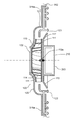
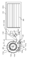
- FIG. 1A is a cross-sectional view showing a temperature conditioning unit 10 according to Embodiment 1 of the present invention.
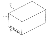
- FIG. 1B is a perspective view showing the temperature conditioning unit 10.
- 1C is an enlarged view of a main part of the temperature conditioning unit shown in FIG. 1A.
- FIG. 2 is a cross-sectional view showing another configuration example of the temperature conditioning unit 10 according to Embodiment 1 of the present invention.
- the temperature conditioning unit 10 is packaged by a housing 300.
- the housing 300 includes an outer surface 302 to which the fan case 120 is attached. The following components are accommodated in the housing 300.
- a blower 100 that is a centrifugal blower element includes a plurality of moving blades 111, an impeller 110 (centrifugal fan) having a substantially disk-shaped impeller disk 112 that connects the moving blades 111, and a rotation axis of the impeller 100.
- a substantially cylindrical side wall 121 and a fan case 120 having a circular intake hole 122 centered on the rotation axis on a plane perpendicular to the rotation axis are formed.
- the impeller 110 is connected and fixed to an electric motor 200 that is a rotational drive source via a shaft 210.
- the electric motor 200 that is a rotational drive source includes a shaft 210.
- the impeller 110 When the electric motor 200 that is a rotational drive source is rotationally driven, the impeller 110 is rotated, and air energized through the intake holes 122 of the fan case 120 and given energy by the moving blades 111 is substantially perpendicular to the rotational axis. Discharged in the direction. The discharge flow is redirected in the anti-suction direction of the rotating shaft by the side wall 121 of the fan case 120 having the first airflow guiding shape.
- the shape of the inner wall of the side wall 121 is preferably a gentle curved surface so as not to hinder the flow of airflow.
- the almost uniform airflow that flows out from the discharge hole 123 of the fan case 120 is sent into the housing 300 to cool parts such as the battery pack of the temperature-harmonized object 350 that is arranged in the housing 300. Or warm up.
- the discharge hole 123 is located on the opposite side of the intake hole 122 with respect to the side wall 121 in the direction along the rotation axis.
- the impeller 110 includes a rotation shaft of the electric motor 200 that is a rotation drive source in the center, and a substantially disc-shaped impeller disk 112 disposed on a surface perpendicular to the rotation shaft, and one surface of the impeller disk 112. And a plurality of moving blades 111 standing on the side of the intake hole.
- Impeller 110 further includes a shroud 114.
- the aspect of the shroud 114 is an annular plate that covers each end of the rotor blade 111 of the impeller 110 on the intake hole side.
- the shape of the shroud 114 is a funnel shape, a morning glory shape, or a trumpet shape having a hole at the center.
- the wide mouth side of the shroud 114 faces the impeller disk 112 side, and the narrow mouth side of the shroud 114 faces the intake hole side.
- the outer peripheral end portion of the impeller disk 112 is provided with an inclined portion 113 that is inclined in the air supply direction so as to reduce the blowing resistance against the flow of the airflow.
- blowing resistance that is, pressure loss is increased. Therefore, when the volume occupied by the object to be conditioned is large with respect to the casing, an intake side chamber in which fluid is accumulated is provided on the inflow surface of the object to be conditioned, and an exhaust side chamber in which fluid is accumulated on the outflow surface of the object to be conditioned. . As a result, the air is blown substantially uniformly to the temperature-controlled object.
- the intake-side chamber and the exhaust-side chamber are often suppressed to a minimum area in order to reduce the size of electrical equipment.
- casing is high, high output is calculated
- the temperature conditioning unit 10 of the present embodiment employs a centrifugal fan element having a high static pressure, so that sufficient cooling air can be ventilated even if the intake side chamber and the exhaust side chamber are flat. Either or both of the intake side chamber and the exhaust side chamber may be arranged in the blower 100 which is a centrifugal blower element.
- FIG. 1A shows a state in which a blower 100, which is a centrifugal blower element, is installed on an isolation wall 311 constituting the intake side chamber 311a.
- 1C is an enlarged view of a main part of the temperature conditioning unit shown in FIG. 1A.
- the temperature harmony unit 10 of this Embodiment gives the flow velocity distribution with little bias to the housing
- the constituent members of the impeller 110 of the present embodiment can be made of metal or resin material, and are not particularly limited.
- the material of the stator winding of the electric motor that is the rotational drive source is copper, copper alloy, aluminum, or aluminum alloy, and is not particularly limited.
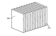
- FIG. 3 is a perspective view of the temperature-harmonized object 350 according to the first embodiment of the present invention.
- the temperature-harmonized object 350 is composed of a complex of a substantially rectangular parallelepiped (a heating element 351).
- the rectangular parallelepipeds are arranged at substantially equal intervals so that the surfaces having the largest area of the rectangular parallelepiped face each other.
- the pressure resistance in the direction in which the cooling air to be temperature-controlled is flowing becomes equal between the heating elements 351 constituting the temperature-controlled objects. For this reason, the area
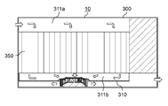
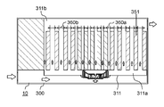
- FIG. 4 is a cross-sectional view showing still another configuration example of the temperature conditioning unit 10 according to the first embodiment of the present invention.
- FIG. 5 is a perspective view of another temperature-harmonized object 350 according to Embodiment 1 of the present invention.
- the interval 360a of the heating elements 351 is narrowed at the portion corresponding to the portion where the flow rate of the discharge flow from the blower is fast, and the interval 360b of the heating element 351 is set at the portion corresponding to the portion where the flow rate is slow.
- the pressure resistance of the temperature-harmonized object 350 can be arbitrarily adjusted. Therefore, it is possible to cool the heating elements 351 without deviation.
- the temperature-harmonized blocks 352 configured by a plurality of heating elements 351 may be arranged with different directions for each block.
- FIG. 6 is a perspective view showing another configuration example of the temperature conditioning unit 10 according to the first embodiment of the present invention.
- the temperature conditioning unit 10 in FIG. 6 is an electrical device in which the intake side chamber 311a is configured by a plurality of spaces.
- a blower 100 which is a centrifugal blower element, is disposed on the isolation wall 311 at the boundary of the intake side chamber 311a. This eliminates the need for a discharge flow rate relative to a low flow velocity region near the anti-suction surface of the blower 100 that is a centrifugal blower element. Therefore, the flow velocity distribution in the intake side chamber 311a is more easily made uniform.
- the present invention is not limited to this.
- the temperature conditioning unit 10 of the present embodiment can also be applied to engine control units, inverter devices, motor temperature conditioning, and the like.
- the temperature conditioning unit 10 includes the impeller 110, the rotational drive source 200, the fan case 120, the housing 300, and at least one of the intake side chamber 311a and the exhaust side chamber 311b.
- the impeller 110 includes a rotation shaft 112a at the center, and is disposed on a plane perpendicular to the rotation shaft 112a.
- the impeller disk 112 and the impeller disk 112 on one side of the intake hole 122 side.
- a plurality of moving blades 111 erected.
- the rotational drive source 200 includes a shaft 210 and is connected to the impeller 110 via the shaft 210.
- the fan case 120 includes a substantially cylindrical side wall 121 formed around the rotation shaft 112a, a circular intake hole 122 centered on the rotation shaft 112a in a plane perpendicular to the rotation shaft 112a, and the rotation shaft 112a. And a discharge hole 123 positioned on the side opposite to the intake hole 122 with respect to the side wall 121.
- the housing 300 includes an outer surface 302 to which the fan case 120 is attached, and a temperature-harmonized object 350 is accommodated therein.
- the intake-side chamber 311a fluid accumulates on the inflow surface of the temperature-controlled object 350.
- the exhaust side chamber 311b a fluid accumulates on the outflow surface of the temperature-controlled object 350.
- the temperature-harmonized object 350 is a substantially rectangular parallelepiped, and may include at least one set of heating elements 351 disposed so that the surfaces having the largest area of the rectangular parallelepiped face each other. Thereby, the area
- the temperature conditioning unit 10 of the present embodiment has both an intake side chamber 311a and an exhaust side chamber 311b, and a blower 100 for temperature conditioning is installed in at least one of the intake side chamber 311a and the exhaust side chamber 311b. May be.
- the temperature harmony unit 10 of this Embodiment gives the flow velocity distribution with little bias to the housing
- the temperature conditioning unit 10 of the present embodiment has both an intake side chamber 311a and an exhaust side chamber 311b, and the volume of the intake side chamber 311a and the volume of the exhaust side chamber 311b are equal or different from each other. Also good.
- the volume of the exhaust side chamber 311b may be smaller than the volume of the intake side chamber 311a. In this way, the pressure resistance of the surface of the intake side chamber 311a facing the temperature-harmonized object 350 and the value of the pressure resistance of the surface of the exhaust side chamber 311b facing the temperature-tuned object 350 are adjusted. It is possible to cool the heating element 351 without deviation.
- the temperature conditioning unit 10 of the present embodiment may further include a rotation drive source 200 that rotationally drives the rotation shaft 112a of the impeller 110.
- the stator winding of the rotary drive source 200 may include any of copper, copper alloy, aluminum, or aluminum alloy.
- the impeller 110 may include a metal or a resin.
- FIG. 7 is a system configuration diagram showing an overview of the temperature conditioning system 20 according to Embodiment 2 of the present invention.
- FIG. 8 is a system configuration diagram showing an outline of another temperature conditioning system 20a according to Embodiment 2 of the present invention.
- FIG. 9 is a system configuration diagram showing an outline of still another temperature conditioning system 20b according to Embodiment 2 of the present invention.
- FIG. 10 is a schematic diagram showing an outline of the vehicle 30 in the second embodiment of the present invention.
- FIG. 11 is a schematic diagram showing an outline of another vehicle 30a according to the second embodiment of the present invention.
- the temperature conditioning system according to the second embodiment has the following configuration.
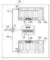
- the temperature conditioning system 20 in the second embodiment includes a first temperature conditioning unit 711a, a second temperature conditioning unit 711b, and a plurality of ducts 700, 700a, 700b, 700c, and 700d. , A switching unit 701, a rotation speed control unit 702, and a control unit 703.
- the temperature conditioning unit 10 described in the first embodiment can be used as the first temperature conditioning unit 711a and the second temperature conditioning unit 711b.
- FIG. 7 shows the temperature conditioning unit described in Embodiment 1 using FIG. 1A.
- Ducts 700b and 700c which are a part of the plurality of ducts, connect the exhaust hole 125a included in the first temperature adjustment unit 711a and the intake hole 122b included in the second temperature adjustment unit 711b.
- the intake hole 122b sucks air into the housing.
- the exhaust hole 125a discharges the sucked air out of the housing.
- the ducts 700 and 700a which are a part of the plurality of ducts connect the intake hole 122a included in the first temperature adjustment unit 711a and the exhaust hole 125b included in the second temperature adjustment unit 711b.
- the switching unit 701 switches the state in which the ducts 700, 700a, and 700d are connected.
- the rotation speed control unit 702 controls at least one of the rotation speed of the electric motor 200a included in the first temperature adjustment unit 711a and the rotation speed of the electric motor 200b included in the second temperature adjustment unit 711b.
- the control unit 703 controls the switching unit 701 and the rotation speed control unit 702.
- the control unit 703 controls the flow path of air flowing through the plurality of ducts 700, 700a, 700b, 700c, and 700d or the air volume of air.
- the temperature conditioning system 20a in Embodiment 2 includes a first temperature conditioning unit 720a, a second temperature conditioning unit 720b, a plurality of ducts 700, 700e, and 700f, and a switching unit 701. And a rotation speed control unit 702 and a control unit 703.
- FIG. 8 shows the temperature conditioning unit described in Embodiment 1 using FIG. 1B.
- Ducts 700 and 700e which are a part of the plurality of ducts, connect the intake hole 122a included in the first temperature adjustment unit 720a and the intake hole 122b included in the second temperature adjustment unit 720b.
- the plurality of ducts 700, 700e, and 700f may connect the exhaust hole 125a included in the first temperature adjustment unit 720a and the exhaust hole 125b included in the second temperature adjustment unit 720b.
- the switching unit 701 switches the connection state of the plurality of ducts 700, 700e, and 700f.
- the rotation speed control unit 702 controls at least one of the rotation speed of the electric motor 200a included in the first temperature adjustment unit 720a and the rotation speed of the electric motor 200b included in the second temperature adjustment unit 720b.
- the control unit 703 controls the switching unit 701 and the rotation speed control unit 702.
- the control unit 703 controls a flow path of air flowing in the plurality of ducts 700, 700e, and 700f or an air volume of air.
- the temperature conditioning system 20b in Embodiment 2 includes the temperature conditioning unit 10a, the first ducts 730, 730a, and 730b, the second ducts 730c, 730d, and the switching unit 701a. , 701b, a rotation speed control unit 702, and a control unit 703.
- the temperature conditioning unit described in the first embodiment can be used as the temperature conditioning unit 10a.
- FIG. 9 shows the temperature conditioning unit described with reference to FIG. 1B in the first embodiment.
- the first ducts 730, 730a, and 730b allow air to flow without passing through the temperature conditioning unit 10a.
- the second duct 730c flows the air supplied to the temperature conditioning unit 10a.
- the second duct 730d allows the air discharged from the temperature conditioning unit 10a to flow. Air is sucked from the suction holes 122. Air is exhausted from the exhaust hole 125.
- the first ducts 730, 730a, 730b and the second ducts 730c, 730d are connected to the switching units 701a, 701b.
- the switching units 701a and 701b switch the air flow.
- the rotation speed control unit 702 controls at least the rotation speed of the electric motor 200 included in the temperature conditioning unit 10a.
- the control unit 703 controls the switching units 701a and 701b and the rotation speed control unit 702.
- the control unit 703 controls the flow path of air flowing through the first ducts 730, 730a, and 730b and the second ducts 730c and 730d, or the air volume of the air.
- FIG. 10 is a schematic diagram showing an outline of the vehicle 30 in the second embodiment of the present invention.
- the vehicle 30 includes a power source 800, drive wheels 801, a travel control unit 802, and a temperature conditioning system 803.
- the driving wheel 801 is driven by the power supplied from the power source 800.
- the travel control unit 802 controls the power source 800.
- the temperature conditioning system 803 can use the temperature conditioning systems 20, 20a, and 20b described above.
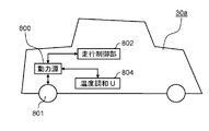
- FIG. 11 is a schematic diagram showing an outline of another vehicle 30a according to the second embodiment of the present invention.
- the vehicle 30a includes a power source 800, drive wheels 801, a travel control unit 802, and a temperature conditioning unit 804.
- the driving wheel 801 is driven by the power supplied from the power source 800.
- the travel control unit 802 controls the power source 800.
- the temperature conditioning system 803 As shown in FIG. 10, the temperature conditioning system 803 according to the second embodiment is mounted on the vehicle 30.
- the temperature conditioning system 803 When the temperature conditioning system 803 is mounted on the vehicle 30, if the following configuration is adopted, the temperature-controlled member is cooled and heated effectively.
- the temperature adjustment system 803 includes a plurality of ducts that connect the intake holes and the vent holes of each temperature adjustment unit.
- the temperature conditioning system 803 includes a switching unit that switches an amount of airflow flowing in the duct or a path for flowing the airflow.
- a plurality of temperature conditioning units are connected by a duct. With this configuration, it is possible to efficiently harmonize the temperature-controlled member.
- the temperature conditioning system 803 has a plurality of ducts that are connected to the intake and vent holes of the temperature conditioning unit.
- the temperature conditioning system 803 includes a switching unit that switches an amount of airflow flowing in the duct or a path for flowing the airflow.
- a plurality of ducts are connected to the intake and vent holes of the temperature conditioning unit.
- the duct 730 has one end connected to the outside of the vehicle and the other end connected to the switching unit 701a.
- the duct 730a has one end connected to the switching unit 701a and the other end connected to the switching unit 701b.
- one end of the duct 730c is connected to the switching unit 701a, and the other end is connected to the intake hole 122 of the temperature conditioning unit 10a.
- One end of the duct 730d is connected to the exhaust hole 125 of the temperature conditioning unit 10a, and the other end is connected to the switching unit 701b.
- the air outside the vehicle when the outside air temperature of the vehicle 30 is within a predetermined range, the air outside the vehicle can be directly taken into the vehicle 30 through the duct.
- the outside air temperature of the vehicle 30 is outside the predetermined range, air outside the vehicle can be taken into the vehicle 30 through the duct and the temperature conditioning unit.
- the temperature conditioning system 803 can switch the air provided to the temperature-controlled member according to the outside air temperature of the vehicle. Therefore, the temperature harmony system 803 can realize the temperature harmony of the temperature-tuned member while efficiently realizing energy saving.
- the threshold of the external temperature of the vehicle for switching the duct may be set as appropriate according to the purpose.
- the intake of air outside the vehicle for switching the duct can be switched by atmospheric pressure instead of the temperature outside the vehicle.
- the description of the vehicle shown in FIG. 11 can be used by replacing the temperature adjustment system 803 of the vehicle shown in FIG. 10 with the temperature adjustment unit 804.
- the temperature conditioning unit according to the present embodiment further has an exhaust hole for discharging the air sucked into the casing to the outside of the casing. Thereby, the air sucked into the housing can be discharged out of the housing.
- the temperature conditioning system 20 or 20a of the present embodiment includes the first temperature conditioning unit, the second temperature conditioning unit, and the exhaust holes 122a or the intake holes 125a included in the first temperature conditioning unit. And a plurality of ducts connecting the intake holes 122b or the exhaust holes 125b of the second temperature conditioning unit.
- the temperature conditioning system of the present embodiment includes a switching unit that switches a state in which a plurality of ducts are connected, at least the rotational speed of the rotational drive source included in the first temperature conditioning unit, or the second temperature conditioning.
- a rotation speed control unit 702 that controls one of the rotation speeds of the rotation drive source of the unit, a switching unit and a rotation speed control unit 702 are controlled, and a flow path of air flowing in a plurality of ducts or a flow of air And a control unit 703 for controlling the air volume.
- the temperature conditioning system 20b of the present embodiment is supplied to the temperature conditioning unit 10a, the first ducts 730, 730a, and 730b that allow air to flow without passing through the temperature conditioning unit 10a, and the temperature conditioning unit 10a.
- the second ducts 730c and 730d for flowing air or the air discharged from the temperature conditioning unit 10a are connected to the first duct and the second duct, and the switching units 701a and 701b for switching the air flow. And comprising.
- the temperature conditioning system 20b controls the rotation speed control unit 702 that controls the rotation speed of the rotation drive source included in the temperature conditioning unit 10a, the switching units 701a and 701b, and the rotation speed control unit 702.
- thermo harmony system of this Embodiment can implement
- the vehicle 30 of the present embodiment includes a power source 800, drive wheels 801 that are driven by power supplied from the power source 800, a travel control unit 802 that controls the power source 800, and a temperature conditioning system 803. .
- the temperature harmony system 803 can switch the air provided to a to-be-temperature-regulated member according to the external temperature of a vehicle. Therefore, the temperature harmony system 803 can realize the temperature harmony of the temperature-tuned member while efficiently realizing energy saving.
- the vehicle 30 a includes a power source 800, drive wheels 801 that are driven by power supplied from the power source 800, a travel control unit 802 that controls the power source 800, and a temperature conditioning unit 804.
- the temperature harmony unit 804 can switch the air provided to a to-be-temperature-regulated member according to the external temperature of a vehicle. Therefore, the temperature harmony unit 804 can implement
- the temperature conditioning unit and temperature conditioning system of the present invention can be reduced in size, increased in output, and improved in efficiency, and are useful for on-vehicle battery temperature control applications. Moreover, the mounting of the temperature conditioning unit and the temperature conditioning system of the present invention on a vehicle does not cause excessive vibration or noise.
Landscapes
- Engineering & Computer Science (AREA)
- Chemical & Material Sciences (AREA)
- Mechanical Engineering (AREA)
- Electrochemistry (AREA)
- Manufacturing & Machinery (AREA)
- Chemical Kinetics & Catalysis (AREA)
- General Chemical & Material Sciences (AREA)
- General Engineering & Computer Science (AREA)
- Combustion & Propulsion (AREA)
- Transportation (AREA)
- Automation & Control Theory (AREA)
- Air-Conditioning For Vehicles (AREA)
- Secondary Cells (AREA)
- Cooling, Air Intake And Gas Exhaust, And Fuel Tank Arrangements In Propulsion Units (AREA)
Abstract
Priority Applications (3)
| Application Number | Priority Date | Filing Date | Title |
|---|---|---|---|
| CN201680035398.XA CN107710495B (zh) | 2015-07-24 | 2016-07-14 | 温度调节单元、温度调节系统、车辆 |
| JP2017531003A JP6678302B2 (ja) | 2015-07-24 | 2016-07-14 | 温度調和ユニット、温度調和システム、車両 |
| US15/574,568 US20200127345A2 (en) | 2015-07-24 | 2016-07-14 | Temperature conditioning unit, temperature conditioning system, and vehicle |
Applications Claiming Priority (2)
| Application Number | Priority Date | Filing Date | Title |
|---|---|---|---|
| JP2015-146698 | 2015-07-24 | ||
| JP2015146698 | 2015-07-24 |
Publications (1)
| Publication Number | Publication Date |
|---|---|
| WO2017017922A1 true WO2017017922A1 (fr) | 2017-02-02 |
Family
ID=57884172
Family Applications (1)
| Application Number | Title | Priority Date | Filing Date |
|---|---|---|---|
| PCT/JP2016/003325 Ceased WO2017017922A1 (fr) | 2015-07-24 | 2016-07-14 | Unité de conditionnement en température, système de conditionnement en température et véhicule |
Country Status (4)
| Country | Link |
|---|---|
| US (1) | US20200127345A2 (fr) |
| JP (1) | JP6678302B2 (fr) |
| CN (1) | CN107710495B (fr) |
| WO (1) | WO2017017922A1 (fr) |
Cited By (1)
| Publication number | Priority date | Publication date | Assignee | Title |
|---|---|---|---|---|
| WO2025073399A1 (fr) * | 2023-10-06 | 2025-04-10 | Mercedes-Benz Group AG | Intégration d'un moteur/unité de réglage dans un boîtier de batterie d'un véhicule électrique |
Families Citing this family (6)
| Publication number | Priority date | Publication date | Assignee | Title |
|---|---|---|---|---|
| KR102142669B1 (ko) * | 2017-02-24 | 2020-08-07 | 주식회사 엘지화학 | 가이드 베인을 구비한 공냉식 배터리 모듈 |
| GB2576360A (en) * | 2018-08-16 | 2020-02-19 | Hyperdrive Innovation Ltd | Method and apparatus |
| CN109524744B (zh) * | 2018-10-30 | 2021-01-19 | 华南理工大学 | 一种电池热管理风冷系统及其快速构造方法 |
| DE102020005539A1 (de) * | 2019-10-02 | 2021-04-08 | Sew-Eurodrive Gmbh & Co Kg | Energiespeicher mit einer Speichermodulanordnung mit Lüfter |
| DE102021200079A1 (de) | 2021-01-07 | 2022-07-07 | Robert Bosch Gesellschaft mit beschränkter Haftung | Batteriemodul mit einer Mehrzahl an Batteriezellen und Verwendung eines solchen |
| CN115207516A (zh) * | 2022-08-01 | 2022-10-18 | 南通国轩新能源科技有限公司 | 一种风冷式锂电池储能仓及风冷方法 |
Citations (3)
| Publication number | Priority date | Publication date | Assignee | Title |
|---|---|---|---|---|
| JP2006228521A (ja) * | 2005-02-16 | 2006-08-31 | Panasonic Ev Energy Co Ltd | ファン構造及び電池パック |
| JP2012023141A (ja) * | 2010-07-13 | 2012-02-02 | Valeo Japan Co Ltd | 発熱体冷却ユニット |
| WO2015190077A1 (fr) * | 2014-06-11 | 2015-12-17 | パナソニックIpマネジメント株式会社 | Unité de conditionnement de température, système de conditionnement de température, et véhicule équipé de ladite unité de conditionnement de température |
Family Cites Families (137)
| Publication number | Priority date | Publication date | Assignee | Title |
|---|---|---|---|---|
| US6394210B2 (en) * | 1999-06-07 | 2002-05-28 | Mitsubishi Heavy Industries, Ltd. | Temperature controller for vehicular battery |
| JP2001167806A (ja) * | 1999-12-09 | 2001-06-22 | Toyota Motor Corp | 車載電池パック |
| US6649290B2 (en) * | 2001-05-11 | 2003-11-18 | Cellex Power Products, Inc. | Fuel cell thermal management system and method |
| JP4320133B2 (ja) * | 2001-06-05 | 2009-08-26 | パナソニック株式会社 | 電池電源装置 |
| JP2003007356A (ja) * | 2001-06-25 | 2003-01-10 | Matsushita Refrig Co Ltd | 蓄電池の温度調節装置とそれを搭載した移動車 |
| US7241530B2 (en) * | 2002-07-23 | 2007-07-10 | Nissan Motor Co., Ltd. | Module battery |
| US20050026014A1 (en) * | 2003-07-31 | 2005-02-03 | Michael Fogaing | Polymer batteries having thermal exchange apparatus |
| WO2005043650A2 (fr) * | 2003-10-28 | 2005-05-12 | Johnson Controls Technology Company | Systeme de batterie |
| JP2005353410A (ja) * | 2004-06-10 | 2005-12-22 | Toyota Motor Corp | 燃料電池用冷却装置及びそれを搭載した車両 |
| WO2006022362A2 (fr) * | 2004-08-25 | 2006-03-02 | Toyota Motor Co Ltd | Dispositif de source d'energie electrique |
| KR100833797B1 (ko) * | 2004-11-02 | 2008-05-30 | 주식회사 엘지화학 | 전지팩의 온도 제어 방법 |
| CA2531656A1 (fr) * | 2004-12-29 | 2006-06-29 | Odyne Corporation | Enceinte de batteries pour vehicules electriques et vehicules electriques hybrides, optimisee pour le refroidissement a l'air |
| JP4781071B2 (ja) * | 2005-09-28 | 2011-09-28 | 三洋電機株式会社 | 電源装置と電池の冷却方法 |
| JP4017003B2 (ja) * | 2005-09-30 | 2007-12-05 | ダイキン工業株式会社 | 遠心ファン及びこれを用いた空気調和機 |
| CN2842750Y (zh) * | 2005-11-21 | 2006-11-29 | 北京有色金属研究总院 | 一种便于电池通风散热的电池箱体 |
| KR101212369B1 (ko) * | 2006-01-05 | 2012-12-13 | 에스케이이노베이션 주식회사 | 리튬 2차 전지 시스템의 냉각구조 |
| US8872474B2 (en) * | 2006-02-09 | 2014-10-28 | Karl F. Scheucher | Fail safe serviceable high voltage battery pack |
| US8026698B2 (en) * | 2006-02-09 | 2011-09-27 | Scheucher Karl F | Scalable intelligent power supply system and method |
| JP2007250374A (ja) * | 2006-03-16 | 2007-09-27 | Denso Corp | 燃料電池システム |
| DE102006029960A1 (de) * | 2006-06-29 | 2008-01-03 | BSH Bosch und Siemens Hausgeräte GmbH | Trockner mit verringerter Geräuschentwicklung, hierfür geeignetes Gebläse und Läuferrad sowie Verfahren zur Herstellung des Läuferrades |
| JP2008069672A (ja) * | 2006-09-12 | 2008-03-27 | Nippon Densan Corp | ファン |
| KR20090043566A (ko) * | 2006-09-18 | 2009-05-06 | 마그나 스티어 파르초이크테시닉 아게 운트 코. 카게 | 모듈 방식의 배터리 유닛 |
| US20080299448A1 (en) * | 2006-11-20 | 2008-12-04 | Derrick Scott Buck | Battery unit with temperature control device |
| KR100862436B1 (ko) * | 2006-11-29 | 2008-10-08 | 현대자동차주식회사 | 배터리 모듈 냉각용 지지장치 |
| CN101627490B (zh) * | 2006-12-14 | 2012-10-03 | 江森自控帅福得先进能源动力系统有限责任公司 | 电池模块 |
| WO2008099602A1 (fr) * | 2007-02-16 | 2008-08-21 | Panasonic Corporation | Unité de stockage en énergie électrique |
| US20100047682A1 (en) * | 2007-03-01 | 2010-02-25 | Johnson Controls - SAFT Advanced Power Solutions, LLC | Battery system and thermal management system therefor |
| US7828520B2 (en) * | 2007-03-14 | 2010-11-09 | Asia Vital Components Co., Ltd. | Fan |
| JP4529991B2 (ja) * | 2007-04-03 | 2010-08-25 | 株式会社デンソー | 電池冷却装置 |
| JP2008258027A (ja) * | 2007-04-05 | 2008-10-23 | Denso Corp | 集合電池 |
| JP4337905B2 (ja) * | 2007-04-18 | 2009-09-30 | トヨタ自動車株式会社 | 車両に搭載された電気機器の冷却装置 |
| US20080276631A1 (en) * | 2007-05-07 | 2008-11-13 | Ajith Kuttannair Kumar | System and Method for Cooling a Battery |
| CN101363449A (zh) * | 2007-08-08 | 2009-02-11 | 富准精密工业(深圳)有限公司 | 扇叶结构 |
| CN101372987B (zh) * | 2007-08-24 | 2012-09-19 | 富准精密工业(深圳)有限公司 | 扇叶结构及具有该扇叶结构的离心风扇 |
| US20090071178A1 (en) * | 2007-09-14 | 2009-03-19 | Gm Global Technology Operations, Inc. | Vehicle HVAC and Battery Thermal Management |
| US8029343B2 (en) * | 2007-10-02 | 2011-10-04 | Gm Global Technology Operations, Llc | Vehicle body pressure relief system |
| JP4569640B2 (ja) * | 2008-01-31 | 2010-10-27 | 株式会社デンソー | 電池の温度調整装置 |
| CN101498317B (zh) * | 2008-02-01 | 2012-03-14 | 富准精密工业(深圳)有限公司 | 散热风扇及其叶轮 |
| TWI378183B (en) * | 2008-03-31 | 2012-12-01 | Delta Electronics Inc | Fan and impeller thereof |
| JP5193660B2 (ja) * | 2008-04-03 | 2013-05-08 | 株式会社日立製作所 | 電池モジュール及びそれを備えた蓄電装置並びに電機システム |
| JP5331517B2 (ja) * | 2008-04-14 | 2013-10-30 | 日産自動車株式会社 | 組電池、および組電池を搭載した車両 |
| JP5405858B2 (ja) * | 2008-04-14 | 2014-02-05 | 日産自動車株式会社 | 組電池、組電池の製造方法および組電池を搭載した車両 |
| WO2009140199A2 (fr) * | 2008-05-10 | 2009-11-19 | Enerdel, Inc. | Ensemble batterie |
| TW201001141A (en) * | 2008-06-25 | 2010-01-01 | Micro Star Int Co Ltd | Wind guiding structure |
| CN101685332B (zh) * | 2008-09-25 | 2013-04-24 | 索尼株式会社 | 冷却装置、电子装置和送风装置 |
| CN101725562A (zh) * | 2008-10-28 | 2010-06-09 | 富准精密工业(深圳)有限公司 | 散热风扇及其叶轮 |
| US20100104927A1 (en) * | 2008-10-29 | 2010-04-29 | Scott Albright | Temperature-controlled battery configuration |
| US8082743B2 (en) * | 2009-02-20 | 2011-12-27 | Tesla Motors, Inc. | Battery pack temperature optimization control system |
| US20100239892A1 (en) * | 2009-03-20 | 2010-09-23 | Dennis Kramer | Heavy vehicle battery pack with improved cooling scheme |
| CN201466117U (zh) * | 2009-07-24 | 2010-05-12 | 岑显荣 | 一种带冷却外壳的电动汽车蓄电池及其冷却装置 |
| CN102473981B (zh) * | 2009-09-30 | 2014-11-12 | 株式会社日立制作所 | 蓄电模块 |
| DE102009053506A1 (de) * | 2009-11-16 | 2011-05-19 | Li-Tec Battery Gmbh | Batteriegehäuse zur Aufnahme von elektrochemischen Energiespeichereinrichtungen |
| FR2954405B1 (fr) * | 2009-12-22 | 2012-01-13 | Renault Sa | Dispositif de refroidissement pour vehicule automobile |
| WO2011082226A2 (fr) * | 2009-12-30 | 2011-07-07 | A123 Systems, Inc. | Système de module de batterie |
| US7975637B1 (en) * | 2010-02-08 | 2011-07-12 | Brunswick Corporation | Temperature control system for a hybrid vehicle |
| US20110165829A1 (en) * | 2010-02-25 | 2011-07-07 | Ford Global Technologies, Llc | Automotive vehicle and method for operating climate system of same |
| US9004868B2 (en) * | 2010-05-19 | 2015-04-14 | The New York Blower Company | Industrial fan impeller having a tapered blade and method |
| EP2582022A1 (fr) * | 2010-06-14 | 2013-04-17 | Panasonic Corporation | Moteur et climatiseur de véhicule utilisant celui-ci |
| JP5198522B2 (ja) * | 2010-08-31 | 2013-05-15 | トヨタ自動車株式会社 | 蓄電装置および車両 |
| KR101486550B1 (ko) * | 2010-11-16 | 2015-01-23 | 삼성전자 주식회사 | 송풍용 원심팬 및 이를 갖는 냉장고 |
| GB2486019B (en) * | 2010-12-02 | 2013-02-20 | Dyson Technology Ltd | A fan |
| US9039362B2 (en) * | 2011-03-14 | 2015-05-26 | Minebea Co., Ltd. | Impeller and centrifugal fan using the same |
| US8684117B2 (en) * | 2011-06-17 | 2014-04-01 | General Electric Company | Methods and systems for cooling in a vehicle |
| US20140202178A1 (en) * | 2011-06-30 | 2014-07-24 | Michael W. Trumbower | Multiple circuit cooling system |
| JP5950228B2 (ja) * | 2011-07-19 | 2016-07-13 | パナソニックIpマネジメント株式会社 | 電子機器 |
| JP5927539B2 (ja) * | 2011-07-25 | 2016-06-01 | パナソニックIpマネジメント株式会社 | 電子機器 |
| JP5919568B2 (ja) * | 2011-07-25 | 2016-05-18 | パナソニックIpマネジメント株式会社 | 電子機器 |
| JP2013047479A (ja) * | 2011-08-29 | 2013-03-07 | Mitsubishi Heavy Ind Ltd | インペラ及びこれを備えた回転機械並びにインペラの製造方法 |
| US9267507B2 (en) * | 2011-10-05 | 2016-02-23 | Asia Vital Components Co., Ltd. | Blade structure for centrifugal fan |
| JP5876268B2 (ja) * | 2011-10-28 | 2016-03-02 | トヨタ自動車株式会社 | 車両 |
| EP2787572B1 (fr) * | 2011-11-30 | 2016-12-28 | Valeo Japan Co., Ltd. | Unité de commande de température de batterie |
| US8974194B2 (en) * | 2011-12-09 | 2015-03-10 | Sunonwealth Electric Machine Industry Co., Ltd. | Advection-type fan and an impeller thereof |
| TWI504812B (zh) * | 2012-02-20 | 2015-10-21 | Quanta Comp Inc | 離心式風扇 |
| US9022751B2 (en) * | 2012-03-13 | 2015-05-05 | Sunonwealth Electric Machine Industry Co., Ltd. | Advection fan and an impeller thereof |
| JP5588472B2 (ja) * | 2012-03-26 | 2014-09-10 | パナソニック株式会社 | 車載用空調装置および車両 |
| CN104604350A (zh) * | 2012-04-26 | 2015-05-06 | Nec平台株式会社 | 气冷式外壳 |
| US9240580B2 (en) * | 2012-05-24 | 2016-01-19 | Samsung Sdi Co., Ltd. | Battery module |
| US8978803B2 (en) * | 2012-06-11 | 2015-03-17 | GM Global Technology Operations LLC | Divided dual inlet housing for an air-based hybrid battery thermal conditioning system |
| JP5522323B1 (ja) * | 2012-07-30 | 2014-06-18 | パナソニック株式会社 | ブロア装置および車両におけるブロア装置の制御方法 |
| TWI490412B (zh) * | 2012-09-18 | 2015-07-01 | Asustek Comp Inc | 離心式風扇 |
| JP6071394B2 (ja) * | 2012-10-03 | 2017-02-01 | ミネベア株式会社 | 遠心式ファン |
| WO2015066359A1 (fr) * | 2013-11-01 | 2015-05-07 | Ambri Inc. | Gestion thermique de batteries à métal liquide |
| JP6220549B2 (ja) * | 2012-10-24 | 2017-10-25 | 株式会社ヴァレオジャパン | バッテリ温度調整ユニット及びそれを用いてなるバッテリモジュール |
| WO2014069270A1 (fr) * | 2012-11-05 | 2014-05-08 | 日産自動車株式会社 | Dispositif de régulation de température de batterie |
| US9777743B2 (en) * | 2012-11-06 | 2017-10-03 | Asia Vital Components Co., Ltd. | Centrifugal fan impeller structure |
| JP5827615B2 (ja) * | 2012-12-27 | 2015-12-02 | トヨタ紡織株式会社 | 車両用排気構造 |
| JP6056499B2 (ja) * | 2013-01-21 | 2017-01-11 | 株式会社豊田自動織機 | バッテリケース |
| JP6099194B2 (ja) * | 2013-01-31 | 2017-03-22 | 本田技研工業株式会社 | 蓄電装置の冷却構造 |
| CN203150677U (zh) * | 2013-03-21 | 2013-08-21 | 中华汽车工业股份有限公司 | 具有冷却单元的电动车电池 |
| TWI487475B (zh) * | 2013-04-02 | 2015-06-01 | 廣達電腦股份有限公司 | 散熱模組 |
| US9541098B2 (en) * | 2013-06-28 | 2017-01-10 | Vyaire Medical Capital Llc | Low-noise blower |
| US9287596B2 (en) * | 2013-07-25 | 2016-03-15 | Ford Global Technologies, Llc | Air-cooled battery module for a vehicle |
| US20150037662A1 (en) * | 2013-07-30 | 2015-02-05 | Johnson Controls Technology Company | System and method for sealing a battery cell |
| KR101636378B1 (ko) * | 2013-08-28 | 2016-07-05 | 주식회사 엘지화학 | 방열 구조를 가지는 단위모듈 제조용 모듈 하우징 및 이를 포함하는 전지모듈 |
| KR101609212B1 (ko) * | 2013-08-28 | 2016-04-05 | 주식회사 엘지화학 | 냉매 및 배기 가스의 혼합을 방지하는 구조를 포함하는 전지모듈 |
| US10106025B2 (en) * | 2013-08-29 | 2018-10-23 | Ford Global Technologies, Llc | High voltage battery cooling plenum |
| CN105518929B (zh) * | 2013-09-06 | 2018-04-20 | 日产自动车株式会社 | 电池组冷却系统 |
| JP6075250B2 (ja) * | 2013-09-10 | 2017-02-08 | トヨタ自動車株式会社 | 蓄電装置の温度調節構造及び温度調節方法 |
| DE102013219200A1 (de) * | 2013-09-24 | 2015-03-26 | Behr Gmbh & Co. Kg | Kühleinrichtung für ein Batteriesystem, insbesondere eines Kraftfahrzeugs |
| JP6187163B2 (ja) * | 2013-10-31 | 2017-08-30 | トヨタ自動車株式会社 | 電池冷却構造 |
| CN104600337A (zh) * | 2013-11-01 | 2015-05-06 | 捷温汽车系统(中国)有限公司 | 用于电化学电源的调温装置 |
| US9765788B2 (en) * | 2013-12-04 | 2017-09-19 | Apple Inc. | Shrouded fan impeller with reduced cover overlap |
| US9651057B2 (en) * | 2013-12-19 | 2017-05-16 | Regal Beloit America, Inc. | Blower assembly including a noise attenuating impeller and method for assembling the same |
| KR101624281B1 (ko) * | 2014-02-17 | 2016-05-25 | 주식회사 엘지화학 | 배터리 모듈 및 이를 포함하는 배터리 팩 |
| CN103825068B (zh) * | 2014-03-07 | 2016-08-17 | 中通客车控股股份有限公司 | 一种新能源客车车用动力电池模组温度控制系统 |
| KR20150108603A (ko) * | 2014-03-18 | 2015-09-30 | 현대모비스 주식회사 | 친환경 자동차의 배터리 모듈 승온장치 및 그 방법 |
| US10263297B2 (en) * | 2014-04-22 | 2019-04-16 | The Boeing Company | Control system for a battery |
| JP6024704B2 (ja) * | 2014-05-09 | 2016-11-16 | 株式会社デンソー | 電池パック |
| JP6624364B2 (ja) * | 2014-07-18 | 2019-12-25 | パナソニックIpマネジメント株式会社 | 電子機器収容ラックおよび蓄電池収容システム |
| JP6417771B2 (ja) * | 2014-07-31 | 2018-11-07 | 日本電産株式会社 | 電動送風機 |
| KR101643864B1 (ko) * | 2014-08-26 | 2016-07-29 | 엘지전자 주식회사 | 차량용 구동모듈 |
| JP6385766B2 (ja) * | 2014-09-17 | 2018-09-05 | 株式会社東芝 | 車両用蓄電池装置 |
| US20160093842A1 (en) * | 2014-09-30 | 2016-03-31 | Google Inc. | Battery module |
| US10658717B2 (en) * | 2014-09-30 | 2020-05-19 | Cps Technology Holdings Llc | Battery module active thermal management features and positioning |
| CN106575727B (zh) * | 2014-10-29 | 2019-04-02 | 株式会社Lg 化学 | 单元单体组 |
| US9752808B2 (en) * | 2014-12-18 | 2017-09-05 | Panasonic Intellectual Property Management Co., Ltd. | Temperature maintaining case |
| CN107709074B (zh) * | 2015-03-06 | 2020-07-28 | 本田技研工业株式会社 | 车辆用高压类设备单元、车辆用电池单元及车辆 |
| JP6497585B2 (ja) * | 2015-06-01 | 2019-04-10 | 株式会社Gsユアサ | 電源装置 |
| JP5856362B1 (ja) * | 2015-06-22 | 2016-02-09 | 株式会社小松製作所 | バッテリ式作業車両及び作業車両用バッテリ |
| JP6384423B2 (ja) * | 2015-08-07 | 2018-09-05 | 株式会社デンソー | 電池パック |
| US10644363B2 (en) * | 2015-09-14 | 2020-05-05 | Panasonic Intellectual Property Management Co., Ltd. | Temperature conditioning unit, temperature conditioning system, and vehicle |
| WO2017056408A1 (fr) * | 2015-09-29 | 2017-04-06 | パナソニックIpマネジメント株式会社 | Accumulateur et dispositif de stockage d'électricité l'utilisant |
| JP6536351B2 (ja) * | 2015-10-27 | 2019-07-03 | スズキ株式会社 | 電動二輪車のスイングアーム |
| JP6210105B2 (ja) * | 2015-11-04 | 2017-10-11 | トヨタ自動車株式会社 | バッテリ装置 |
| KR20170092982A (ko) * | 2016-02-04 | 2017-08-14 | 삼성전자주식회사 | 배터리 열관리 장치 및 방법 |
| US9890797B2 (en) * | 2016-06-22 | 2018-02-13 | Ar Impeller, Inc. | Impeller with removable and replaceable vanes for centrifugal pump |
| JP6893313B2 (ja) * | 2016-06-29 | 2021-06-23 | パナソニックIpマネジメント株式会社 | 電池モジュール |
| CN108075061B (zh) * | 2016-11-09 | 2022-03-08 | Cps科技控股有限公司 | 电池包 |
| KR102155330B1 (ko) * | 2016-11-29 | 2020-09-11 | 주식회사 엘지화학 | 공냉식 배터리 모듈 |
| JP7113177B2 (ja) * | 2016-12-21 | 2022-08-05 | パナソニックIpマネジメント株式会社 | 温度調和ユニット、温度調和システム及び車両 |
| JP6883774B2 (ja) * | 2016-12-27 | 2021-06-09 | パナソニックIpマネジメント株式会社 | 電池モジュール |
| JP2018107087A (ja) * | 2016-12-28 | 2018-07-05 | 三菱自動車工業株式会社 | バッテリーパックの冷却装置 |
| US11978875B2 (en) * | 2017-01-03 | 2024-05-07 | Lg Energy Solution, Ltd. | System for cooling components arranged within an enclosure |
| JP2020057449A (ja) * | 2017-01-31 | 2020-04-09 | 三洋電機株式会社 | ラック型の電源装置 |
| KR102142669B1 (ko) * | 2017-02-24 | 2020-08-07 | 주식회사 엘지화학 | 가이드 베인을 구비한 공냉식 배터리 모듈 |
| KR20190061814A (ko) * | 2017-11-28 | 2019-06-05 | 삼성전자주식회사 | 배터리 열관리 방법 및 장치 |
| KR102580847B1 (ko) * | 2018-04-26 | 2023-09-19 | 에스케이온 주식회사 | 배터리 랙 |
-
2016
- 2016-07-14 JP JP2017531003A patent/JP6678302B2/ja active Active
- 2016-07-14 CN CN201680035398.XA patent/CN107710495B/zh active Active
- 2016-07-14 WO PCT/JP2016/003325 patent/WO2017017922A1/fr not_active Ceased
- 2016-07-14 US US15/574,568 patent/US20200127345A2/en not_active Abandoned
Patent Citations (3)
| Publication number | Priority date | Publication date | Assignee | Title |
|---|---|---|---|---|
| JP2006228521A (ja) * | 2005-02-16 | 2006-08-31 | Panasonic Ev Energy Co Ltd | ファン構造及び電池パック |
| JP2012023141A (ja) * | 2010-07-13 | 2012-02-02 | Valeo Japan Co Ltd | 発熱体冷却ユニット |
| WO2015190077A1 (fr) * | 2014-06-11 | 2015-12-17 | パナソニックIpマネジメント株式会社 | Unité de conditionnement de température, système de conditionnement de température, et véhicule équipé de ladite unité de conditionnement de température |
Cited By (1)
| Publication number | Priority date | Publication date | Assignee | Title |
|---|---|---|---|---|
| WO2025073399A1 (fr) * | 2023-10-06 | 2025-04-10 | Mercedes-Benz Group AG | Intégration d'un moteur/unité de réglage dans un boîtier de batterie d'un véhicule électrique |
Also Published As
| Publication number | Publication date |
|---|---|
| CN107710495A (zh) | 2018-02-16 |
| US20200127345A2 (en) | 2020-04-23 |
| JP6678302B2 (ja) | 2020-04-08 |
| CN107710495B (zh) | 2020-12-01 |
| JPWO2017017922A1 (ja) | 2018-05-24 |
| US20180159188A1 (en) | 2018-06-07 |
Similar Documents
| Publication | Publication Date | Title |
|---|---|---|
| JP6678302B2 (ja) | 温度調和ユニット、温度調和システム、車両 | |
| JP6064179B2 (ja) | 温度調和ユニット、温度調和システムおよび温度調和ユニットを備えた車両 | |
| JP7113177B2 (ja) | 温度調和ユニット、温度調和システム及び車両 | |
| JP6931774B2 (ja) | 温度調和システム、車両 | |
| JP6751854B2 (ja) | 温度調和ユニット、温度調和システム、車両 | |
| US20080219838A1 (en) | Centrifugal fan | |
| JP6931778B2 (ja) | 温度調和システムおよび車両 | |
| JP7029593B2 (ja) | 温度調和ユニット | |
| JP2011252673A (ja) | 冷凍サイクル装置の室外機 | |
| JP7153834B2 (ja) | 温度調和ユニット | |
| WO2020090533A1 (fr) | Mécanisme d'admission/échappement et température | |
| JP2010065945A (ja) | 空気調和装置の室内機およびこれを備えた空気調和装置 | |
| KR100635910B1 (ko) | 소음 저감형 모터 | |
| KR100240947B1 (ko) | 모터의 냉각장치 | |
| JPH09156343A (ja) | 自動車用空気調和装置の送風制御装置 | |
| CN121048245A (zh) | 空调设备和空调设备的控制方法 | |
| WO2020090532A1 (fr) | Machine d'admission/d'échappement et unité de régulation de température | |
| CN112392761A (zh) | 离心风机及空气调节装置 | |
| JPH08219681A (ja) | 熱伝達促進用羽根車およびそれを使用した熱伝達促進装置 | |
| JPH08327115A (ja) | 天井埋め込み形全熱交換換気ユニット | |
| JP2006336508A (ja) | 空気調和機 |
Legal Events
| Date | Code | Title | Description |
|---|---|---|---|
| 121 | Ep: the epo has been informed by wipo that ep was designated in this application |
Ref document number: 16830030 Country of ref document: EP Kind code of ref document: A1 |
|
| ENP | Entry into the national phase |
Ref document number: 2017531003 Country of ref document: JP Kind code of ref document: A |
|
| WWE | Wipo information: entry into national phase |
Ref document number: 15574568 Country of ref document: US |
|
| NENP | Non-entry into the national phase |
Ref country code: DE |
|
| 122 | Ep: pct application non-entry in european phase |
Ref document number: 16830030 Country of ref document: EP Kind code of ref document: A1 |