WO2017017936A1 - Aiguille de ponction médicale et procédé de fabrication d'aiguille de ponction - Google Patents
Aiguille de ponction médicale et procédé de fabrication d'aiguille de ponction Download PDFInfo
- Publication number
- WO2017017936A1 WO2017017936A1 PCT/JP2016/003399 JP2016003399W WO2017017936A1 WO 2017017936 A1 WO2017017936 A1 WO 2017017936A1 JP 2016003399 W JP2016003399 W JP 2016003399W WO 2017017936 A1 WO2017017936 A1 WO 2017017936A1
- Authority
- WO
- WIPO (PCT)
- Prior art keywords
- blade
- blade surface
- surface portion
- central axis
- edge
- Prior art date
- Legal status (The legal status is an assumption and is not a legal conclusion. Google has not performed a legal analysis and makes no representation as to the accuracy of the status listed.)
- Ceased
Links
Images




Classifications
-
- A—HUMAN NECESSITIES
- A61—MEDICAL OR VETERINARY SCIENCE; HYGIENE
- A61B—DIAGNOSIS; SURGERY; IDENTIFICATION
- A61B17/00—Surgical instruments, devices or methods
- A61B17/34—Trocars; Puncturing needles
- A61B17/3417—Details of tips or shafts, e.g. grooves, expandable, bendable; Multiple coaxial sliding cannulas, e.g. for dilating
- A61B17/3421—Cannulas
-
- A—HUMAN NECESSITIES
- A61—MEDICAL OR VETERINARY SCIENCE; HYGIENE
- A61M—DEVICES FOR INTRODUCING MEDIA INTO, OR ONTO, THE BODY; DEVICES FOR TRANSDUCING BODY MEDIA OR FOR TAKING MEDIA FROM THE BODY; DEVICES FOR PRODUCING OR ENDING SLEEP OR STUPOR
- A61M5/00—Devices for bringing media into the body in a subcutaneous, intra-vascular or intramuscular way; Accessories therefor, e.g. filling or cleaning devices, arm-rests
- A61M5/14—Infusion devices, e.g. infusing by gravity; Blood infusion; Accessories therefor
- A61M5/158—Needles for infusions; Accessories therefor, e.g. for inserting infusion needles, or for holding them on the body
-
- A—HUMAN NECESSITIES
- A61—MEDICAL OR VETERINARY SCIENCE; HYGIENE
- A61M—DEVICES FOR INTRODUCING MEDIA INTO, OR ONTO, THE BODY; DEVICES FOR TRANSDUCING BODY MEDIA OR FOR TAKING MEDIA FROM THE BODY; DEVICES FOR PRODUCING OR ENDING SLEEP OR STUPOR
- A61M5/00—Devices for bringing media into the body in a subcutaneous, intra-vascular or intramuscular way; Accessories therefor, e.g. filling or cleaning devices, arm-rests
- A61M5/178—Syringes
- A61M5/31—Details
- A61M5/32—Needles; Details of needles pertaining to their connection with syringe or hub; Accessories for bringing the needle into, or holding the needle on, the body; Devices for protection of needles
-
- A—HUMAN NECESSITIES
- A61—MEDICAL OR VETERINARY SCIENCE; HYGIENE
- A61M—DEVICES FOR INTRODUCING MEDIA INTO, OR ONTO, THE BODY; DEVICES FOR TRANSDUCING BODY MEDIA OR FOR TAKING MEDIA FROM THE BODY; DEVICES FOR PRODUCING OR ENDING SLEEP OR STUPOR
- A61M5/00—Devices for bringing media into the body in a subcutaneous, intra-vascular or intramuscular way; Accessories therefor, e.g. filling or cleaning devices, arm-rests
- A61M5/178—Syringes
- A61M5/31—Details
- A61M5/32—Needles; Details of needles pertaining to their connection with syringe or hub; Accessories for bringing the needle into, or holding the needle on, the body; Devices for protection of needles
- A61M5/3286—Needle tip design, e.g. for improved penetration
-
- B—PERFORMING OPERATIONS; TRANSPORTING
- B21—MECHANICAL METAL-WORKING WITHOUT ESSENTIALLY REMOVING MATERIAL; PUNCHING METAL
- B21G—MAKING NEEDLES, PINS OR NAILS OF METAL
- B21G1/00—Making needles used for performing operations
- B21G1/08—Making needles used for performing operations of hollow needles or needles with hollow end, e.g. hypodermic needles, larding-needles
-
- B—PERFORMING OPERATIONS; TRANSPORTING
- B24—GRINDING; POLISHING
- B24B—MACHINES, DEVICES, OR PROCESSES FOR GRINDING OR POLISHING; DRESSING OR CONDITIONING OF ABRADING SURFACES; FEEDING OF GRINDING, POLISHING, OR LAPPING AGENTS
- B24B19/00—Single-purpose machines or devices for particular grinding operations not covered by any other main group
- B24B19/16—Single-purpose machines or devices for particular grinding operations not covered by any other main group for grinding sharp-pointed workpieces, e.g. needles, pens, fish hooks, tweezers or record player styli
-
- A—HUMAN NECESSITIES
- A61—MEDICAL OR VETERINARY SCIENCE; HYGIENE
- A61B—DIAGNOSIS; SURGERY; IDENTIFICATION
- A61B17/00—Surgical instruments, devices or methods
- A61B2017/00526—Methods of manufacturing
-
- A—HUMAN NECESSITIES
- A61—MEDICAL OR VETERINARY SCIENCE; HYGIENE
- A61B—DIAGNOSIS; SURGERY; IDENTIFICATION
- A61B17/00—Surgical instruments, devices or methods
- A61B17/04—Surgical instruments, devices or methods for suturing wounds; Holders or packages for needles or suture materials
- A61B17/06—Needles ; Sutures; Needle-suture combinations; Holders or packages for needles or suture materials
- A61B17/06066—Needles, e.g. needle tip configurations
- A61B2017/06071—Needles, e.g. needle tip configurations with an abrupt angle formed between two adjacent sections
-
- A—HUMAN NECESSITIES
- A61—MEDICAL OR VETERINARY SCIENCE; HYGIENE
- A61B—DIAGNOSIS; SURGERY; IDENTIFICATION
- A61B17/00—Surgical instruments, devices or methods
- A61B17/04—Surgical instruments, devices or methods for suturing wounds; Holders or packages for needles or suture materials
- A61B17/06—Needles ; Sutures; Needle-suture combinations; Holders or packages for needles or suture materials
- A61B17/06066—Needles, e.g. needle tip configurations
- A61B2017/061—Needles, e.g. needle tip configurations hollow or tubular
-
- A—HUMAN NECESSITIES
- A61—MEDICAL OR VETERINARY SCIENCE; HYGIENE
- A61B—DIAGNOSIS; SURGERY; IDENTIFICATION
- A61B17/00—Surgical instruments, devices or methods
- A61B17/34—Trocars; Puncturing needles
- A61B17/3417—Details of tips or shafts, e.g. grooves, expandable, bendable; Multiple coaxial sliding cannulas, e.g. for dilating
- A61B2017/3454—Details of tips
-
- A—HUMAN NECESSITIES
- A61—MEDICAL OR VETERINARY SCIENCE; HYGIENE
- A61M—DEVICES FOR INTRODUCING MEDIA INTO, OR ONTO, THE BODY; DEVICES FOR TRANSDUCING BODY MEDIA OR FOR TAKING MEDIA FROM THE BODY; DEVICES FOR PRODUCING OR ENDING SLEEP OR STUPOR
- A61M25/00—Catheters; Hollow probes
- A61M25/01—Introducing, guiding, advancing, emplacing or holding catheters
- A61M25/06—Body-piercing guide needles or the like
- A61M25/0606—"Over-the-needle" catheter assemblies, e.g. I.V. catheters
Definitions
- the present invention relates to a medical puncture needle and a method for manufacturing the puncture needle.
- a blade inclined at the distal end with respect to the longitudinal direction of the puncture needle in order to reduce pain when the puncture needle is punctured into a human body What has a surface is known.
- Patent Document 1 discloses a puncture needle of this type having a blade surface whose blade surface shape is a so-called “back cut bevel point” (hereinafter simply referred to as “back cut type”). ing. Since the puncture needle having a backcut type blade surface disclosed in Patent Document 1 is excellent in straightness, for example, at a relatively deep position from the body surface, such as puncture to an artery or puncture to a central vein. It is used when puncturing to a certain target site.
- the puncture needle which has a backcut type blade surface disclosed in Patent Document 1 includes a flat cut surface as a blade surface portion on the front side and a flat backcut surface as a blade surface portion on the back side.
- the ridgeline where the flat cut surface and the back cut surface intersect each other forms a linear cutting edge as a blade edge having the needle tip as one end. Therefore, when the puncture needle disclosed in Patent Document 1 is punctured, the edge of the blade works so as to cut through the skin and the puncture resistance can be reduced, so that the pain felt by the patient or the like is reduced.
- the planar backcut surface becomes small, and it becomes difficult to secure the length of the cutting edge for tearing the skin. For this reason, the skin can be torn by the cutting edge as the blade edge near the needle tip, but when the proximal end of the cutting blade opposite to the needle tip passes through the skin, the outer surface of the puncture needle then forcibly pushes the cut end. Because it is inserted so as to spread, the patient feels the pain when the skin cut is spread.
- an object of the present invention is to provide a puncture needle having a backcut type blade surface that can easily secure the length of the blade edge and a method for manufacturing the puncture needle.
- the medical puncture needle according to the first aspect of the present invention includes a tip including a needle tip, and a rod-shaped main body continuous with the tip, the tip including a blade surface, and the blade
- the surface includes a first blade surface portion that is inclined with respect to a central axis of the main body portion and extends to the needle tip, and a second blade surface portion formed on the back side of the first blade surface portion,
- the angle with respect to the virtual plane in a cross section orthogonal to the central axis direction as it goes toward the needle tip side in the central axis direction It is characterized by comprising the curved surface which increases gradually.
- the blade surface includes a third blade surface portion formed on the back side of the first blade surface portion, and the second blade surface portion and the third blade surface portion are the first blade surface portion. It is preferable to form the blade edge which makes the said needle point an end by the ridgeline which mutually cross
- the third blade surface portion is configured by a curved surface in which an angle with respect to the virtual plane in a cross section orthogonal to the central axis direction gradually increases toward the needle tip side in the central axis direction. It is preferable.
- the virtual plane can be set to one plane that is perpendicular to the first blade surface portion and includes the central axis.
- a medical puncture needle includes a tip including a needle tip, and a rod-shaped main body continuous with the tip, the tip including a blade surface, and the blade The surface is inclined with respect to the central axis of the main body and extends to the needle tip, the second blade surface formed on the back side of the first blade surface, and the first blade surface
- a third blade surface portion formed on the back side of the first blade surface portion, and the second blade surface portion and the third blade surface portion are on the back side of the first blade surface portion, and the needle tip is one end by a ridge line intersecting each other
- the blade edge is formed, and when the blade edge is the first blade edge, the first blade surface portion and the second blade surface portion are the second with the needle tip as one end by a ridge line intersecting each other.
- a blade edge is formed, and the first blade surface portion and the third blade surface portion form a third blade edge having the needle tip as one end by a ridge line intersecting each other.
- Cage, the second blade edge and the third cutting edge is characterized in that it is formed by curves.
- the outer edge of the first blade surface portion includes the second blade edge, the third blade edge, one end of the second blade edge on the body portion side, and the third blade edge.
- a convex curve-shaped main body portion side outer edge portion that connects one end of the main body portion side, and the second blade edge, the third blade edge, and the main body portion side outer edge portion have apexes. It is preferable that they are connected by a continuous curve without intervention.
- the blade surface is formed at the one end by sliding the one end of the rod-like member against the grinding surface of the rotating grindstone.
- a method of manufacturing a medical puncture needle wherein the one end is configured to rotate the rod-shaped member about the central axis of the rod-shaped member and change the tilt angle of the central axis with respect to the grinding surface.
- the blade surface portion formed of a curved surface is formed by sliding the blade to the grinding surface.
- a puncture needle having a back-cut type blade surface that can easily ensure the length of the blade edge and a method for manufacturing the puncture needle.
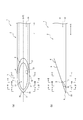
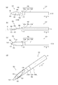
- FIG. 1 (a) is a top view on the front side
- FIG.1 (b) is a side view
- FIG.1 (c) is a top view on the back side
- FIG. 1 (d) is a perspective view.
- Fig.2 (a) is an enlarged view of the front-end
- FIG.2 (b) is an enlarged view of the front-end
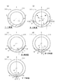
- 3A is a cross-sectional view taken along the line II in FIG. 2
- FIG. 3B is a cross-sectional view taken along the line II-II in FIG. 2
- FIG. 3C is a cross-sectional view taken along the line III-III in FIG. IV-IV sectional view in FIG. 2
- FIG. 3E is a VV sectional view in FIG. It is a figure which shows the puncture needle different from the puncture needle shown in FIG. 1
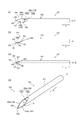
- Fig.4 (a) is a top view of a front side
- FIG.4 (b) is a side view
- FIG.4 (c) is a top view of a back side.
- FIG. 4D is a perspective view.
- Fig.5 (a) is an enlarged view of the front-end
- FIG.5 (b) is an enlarged view of the front-end
- FIGS. 7A and 7B are diagrams showing a modification of the puncture needle shown in FIG. 1, in which FIG. 7A is a front plan view, FIG. 7B is a side view, FIG. 7C is a back plan view, and FIG. (D) is a perspective view. It is a flowchart which shows the manufacturing method of the puncture needle as one Embodiment of this invention.
- FIG. 9A is a schematic diagram showing an outline of the blade surface forming process shown in FIG. 8, FIG. 9A is a schematic diagram of the first blade surface part forming process, FIG. 9B is a schematic diagram of the second blade surface part forming process, FIG. 9 (c) is a schematic diagram of the third blade surface portion forming step.
- FIG. 10A is a diagram showing a modification of the puncture needle shown in FIG. 1, FIG. 10A is a plan view on the front side, FIG. 10B is a side view, FIG. 10C is a plan view on the back side, FIG. (D) is a perspective view.
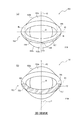
- FIG. 11A is a view of the puncture needle shown in FIG. 10 as viewed from the needle tip side, and FIG. 11B is a cross-sectional view taken along the line XII-XII in FIG.
- FIG. 1 shows a puncture needle 1.
- FIG. 1 (a) is a plan view of the front side of the puncture needle 1
- FIG. 1 (b) is a side view of the puncture needle 1
- FIG. 1 (c) is a plan view of the back side of the puncture needle 1.
- FIG. FIG. 1 (d) is a perspective view of the puncture needle 1.
- the puncture needle 1 includes a main body portion 2 and a distal end portion 3, and defines a hollow portion 10 that communicates from the main body portion 2 to the distal end portion 3.
- the main body portion 2 is a hollow rod shape continuous with the tip portion 3, that is, a tubular tube.
- the main body 2 is a tubular body that is continuous with the distal end portion 3 and has a substantially circular cross-sectional outer shape.
- the “cross section” of the “cross sectional outline” referred to here means a transverse section orthogonal to the central axis O of the main body 2.
- the tip 3 is provided with a blade surface 4, and the blade surface 4 includes a first blade surface portion 5 as a front-side blade surface and a back-side blade surface.
- the puncture needle 1 of the present embodiment includes the blade surface 4 that has been subjected to backcut processing.
- the first blade surface portion 5 is configured by a plane that is inclined with respect to the central axis O of the main body portion 2 and extends to the needle tip 8.
- the 2nd blade surface part 6 and the 3rd blade surface part 7 are comprised by the curved surface, and the blade edge 23 which makes the needle tip 8 one end is formed in the back side of the 1st blade surface part 5 by the ridgeline which mutually cross
- the “needle tip” means the tip of the puncture needle 1 in the axial direction A of the central axis O of the main body 2 (hereinafter simply referred to as “central axial direction A”).
- the first blade surface portion 5 is a flat surface inclined at a predetermined angle such as 12 degrees or 18 degrees with respect to the central axis O, and the inner edge 13 thereof is an opening 11 that is one end of the hollow portion 10 on the distal end portion 3 side. Is partitioned.
- the outer edge 14 of the first blade surface portion 5 is formed by a blade edge 15 and a blade edge 16 having the needle tip 8 as one end, and a main body side outer edge portion 17. Details of the outer edge 14 of the first blade surface portion 5 will be described later.
- the second blade surface portion 6 and the third blade surface portion 7 have a symmetrical shape with respect to a virtual plane that passes through the needle tip 8 and includes the central axis O, and the second blade surface portion 6 and the third blade surface portion 7 are the same.
- a blade edge 23 having the needle tip 8 as one end is formed by a ridge line intersecting with each other.
- the blade edge 23 is linear, and this blade edge 23 also extends on the virtual plane.
- the virtual plane is a plane perpendicular to the first blade surface portion 5.
- center plane X a virtual plane that passes through the needle tip 8 and includes the central axis O
- the second blade surface portion 6 forms a blade edge 15 having the needle tip 8 as one end by a ridge line intersecting with the first blade surface portion 5.
- the blade edge 15 is a part of the outer edge 14 of the first blade surface portion 5, and extends from the needle tip 8 to the terminal point P on the outer edge 14.
- the 3rd blade surface part 7 forms the blade edge 16 which makes the needle tip 8 one end by the ridgeline which 1st blade surface part 5 cross
- This blade edge 16 is also a part of the outer edge 14 of the first blade surface portion 5, and extends from the needle tip 8 to the terminal point Q on the outer edge 14.
- a blade edge 23 formed by a ridge line where the second blade surface portion 6 and the third blade surface portion 7 intersect on the needle tip 8 side will be referred to as a “first blade edge 23”, and the first blade surface portion will be described.
- a blade edge 15 formed by a ridge line where 5 and the second blade surface part 6 intersect each other is referred to as a “second blade edge 15”, and a ridge line where the first blade surface part 5 and the third blade surface part 7 intersect each other.
- the formed blade edge 16 is referred to as “third blade edge 16”.
- the first blade edge 23, the second blade edge 15 and the third blade edge 16 work so as to cut the skin, thereby reducing the piercing resistance.
- the angle of the second blade surface portion 6 with respect to the center plane X in the cross section orthogonal to the center axis direction A varies depending on the position in the center axis direction A.
- the 2nd blade surface part 6 is comprised by the curved surface extended so that it might twist toward the needle-tip 8 side in the central axis direction A like a spiral surface, for example.
- the third blade surface portion 7 is also the same, and is formed of a curved surface extending so as to be twisted toward the needle tip 8 in the central axis direction A, for example, like a spiral surface.
- the 2nd blade surface part 6 and the 3rd blade surface part 7 have a symmetrical shape with respect to the center plane X as mentioned above, and the directions twisted toward the needle tip 8 side are opposite to each other. is there.
- the angle (gamma) with respect to the center plane X in the cross section orthogonal to the center axis direction A increases gradually toward the needle tip 8 side in the center axis direction A. It is composed of curved surfaces. If the 2nd blade surface part 6 is made into such a curved surface, compared with the structure which makes a 2nd blade surface part a plane, it is easy to ensure the length of the 2nd blade edge 15 longer. Moreover, if the 3rd blade surface part 7 is made into such a curved surface, compared with the structure which makes a 3rd blade surface part a plane, it is easy to ensure the length of the 3rd blade edge 16 longer.
- the thickness of the needle in the position in which the 2nd blade surface part 6 is formed is too thin. It is possible to suppress the decrease in the strength of the needle. Furthermore, since it can suppress that thickness becomes thin too much, inferior goods are hard to generate
- the puncture needle 1 of the present embodiment has a central plane in a cross section orthogonal to the central axis direction A as both the second blade surface portion 6 and the third blade surface portion 7 move toward the needle tip 8 side in the central axis direction A.
- the angle ⁇ with respect to X is composed of a curved surface that gradually increases, but either the second blade surface portion 6 or the third blade surface portion 7 is composed of such a curved surface, and the other has a flat surface or another surface shape. You may make it comprise with a curved surface.
- the angle with respect to the central plane X in the cross section orthogonal to the central axis direction A If it is configured by a curved surface in which ⁇ gradually increases, the total length of the second blade edge 15 and the third blade edge 16, that is, the first blade, as compared with the case where only one of them is configured by the above-described curved surface.
- the length from the terminal point P to the terminal point Q through the needle point 8 can be secured longer. Details of the lengths of the second blade edge 15 and the third blade edge 16 will be described later (see FIG. 3).
- the “tip portion” in the present application means a portion of the puncture needle in which the blade surface is formed in the central axis direction A
- the “main body portion” means the central axis direction A of the puncture needle.
- the distal end portion 3 in the present embodiment is the first blade surface portion 5, the second blade surface portion 6, and the third member in the central axis direction A among the tubular members as an integral hollow rod-shaped member constituting the puncture needle 1. This is a portion where the blade surface portion 7 is formed.
- the first blade surface portion 5, the second blade surface portion 6, and the third blade surface portion 7 in the central axial direction A among the integral cylindrical members constituting the puncture needle 1 are the same.
- a metal material such as stainless steel, aluminum or aluminum alloy, titanium or titanium alloy can be used.
- the main body 2 of the present embodiment is a tubular body in which the inner diameter of the inner peripheral surface and the outer diameter of the outer peripheral surface are uniform in the central axis direction A, and the end opposite to the tip 3 side in the central axis direction A
- the unit is connected to a medical instrument such as a syringe through a needle base or the like.
- the inner peripheral surface (the inner peripheral surface of the main body 2 and the inner peripheral surface of the distal end portion 3) of the cylindrical member constituting the entire puncture needle 1 defines the hollow portion 10, and the cylindrical member
- the inner diameter of the inner peripheral surface and the outer diameter of the outer peripheral surface are uniform in the central axis direction A, but are not limited to this configuration.
- the inner diameter of the inner peripheral surface of the cylindrical member and the outer diameter of the outer peripheral surface of the cylindrical member may be configured to gradually decrease toward the distal end portion 3 side in the central axis direction A.
- the outer diameter of the cylindrical member may be tapered so as to gradually decrease toward the tip 3 in the central axis direction A, and the inner diameter of the cylindrical member may be uniform in the central axis direction A. it can.
- the inner diameter of the cylindrical member constituting the puncture needle 1 such as providing a part where the inner diameter gradually decreases or gradually increases toward the distal end portion 3 side in the central axis direction A in a partial region in the central axis direction A and Various configurations can be adopted for the outer diameter according to the use of the puncture needle 1 and the like.
- FIGS. 1 (a) and 1 (b) are enlarged views of the distal end portion 3 shown in FIGS. 1 (a) and 1 (b), respectively.
- 3 (a), (b), (c), (d) and (e) are respectively a II sectional view, a II-II sectional view, a III-III sectional view, an IV-IV sectional view and a VV in FIG. It is sectional drawing.
- the first blade surface portion 5 is a flat surface that is inclined with respect to the central axis direction A.
- one end of the first blade surface portion 5 is a needle tip. 8 and the other end is continuous with the outer peripheral surface of the main body 2.
- the inclination angle of the first blade surface portion 5 with respect to the central axis direction A is larger than the inclination angle of the outer wall of the main body portion 2 with respect to the central axis direction A in the cross section orthogonal to the first blade surface portion 5.
- the outer diameter of the cylindrical member constituting the puncture needle 1 is uniform in the central axis direction A, and the outer wall of the cylindrical member is the central axis in a cross-sectional view orthogonal to the first blade surface portion 5. It extends in direction A. Therefore, if the first blade surface portion 5 is inclined with respect to the central axis direction A, the inclination angle of the first blade surface portion 5 is larger than the inclination angle of the outer wall of the main body portion 2.
- the first blade surface portion 5 has the first blade In a cross section orthogonal to the surface portion 5, the surface portion 5 is not only inclined with respect to the central axis direction A but also inclined with respect to the outer wall of the main body portion 2.
- the outer edge 14 of the first blade surface portion 5 is at one end of the second blade edge 15, the third blade edge 16, and the second blade edge 15 on the main body portion 2 side.
- a main body side outer edge portion 17 having a convex curve shape that connects a terminal point P and a terminal point Q that is one end of the third blade edge 16 on the main body portion 2 side.
- the 2nd blade edge 15 and the 3rd blade edge 16 are formed by the curve, and the 2nd blade edge 15 and the main-body part side outer edge part 17 are connected by the continuous curve without passing through the vertex.
- the second blade edge 15 is continuous with the main body portion side outer edge portion 17 without forming a vertex at the position of the terminal point P which is also a connection point with the main body portion side outer edge portion 17.
- the third blade edge 16 and the main body portion side outer edge portion 17 are also connected by a continuous curve without passing through the apex.
- the third blade edge 16 is connected to the main body portion side outer edge portion 17.
- it is continuous with the main body side outer edge portion 17 without forming a vertex.
- the apex is not formed at the position of the terminal point P or the terminal point Q as in the present embodiment, but the piercing resistance is not greatly increased at the position of the terminal point P or the terminal point Q. It is good also as a structure in which a vertex is formed.
- the second blade surface portion 6 and the third blade surface portion 7 are curved surfaces in which the angle ⁇ with respect to the center plane X in the cross section orthogonal to the center axis direction A gradually increases as going toward the needle tip 8 in the center axis direction A. It consists of Hereinafter, with reference to FIG. 3, the detail of the shape of the 2nd blade surface part 6 and the 3rd blade surface part 7 is demonstrated.
- FIG. 3A is a sectional view taken along the line II in FIG. 2, that is, the position where the first blade surface portion 5 is formed in the central axis direction A, and the second blade surface portion 6 and the third blade surface portion 7 are not formed.
- a cross section perpendicular to the central axis direction A at the position is shown.
- the angle ⁇ with respect to the center plane X of the first blade surface portion 5 in the II cross section of FIG. 2 is 90 degrees.
- the first blade surface portion 5 extends linearly in a direction orthogonal to the central plane X.
- the first blade surface portion 5 is configured by a plane inclined with respect to the central axis O, and therefore in FIGS. 3B to 3E referred to below, FIG. ),
- the angle ⁇ with respect to the central plane X of the first blade surface portion 5 is constant at 90 degrees.
- FIG. 3B shows the II-II cross section of FIG. 2, that is, a cross section passing through the terminal point P of the second blade edge 15 and the terminal point Q of the third blade edge 16 and orthogonal to the central axis direction A.
- FIG. 3B is a cross section orthogonal to the central axis direction A at the ends of the second blade surface portion 6 and the third blade surface portion 7 on the main body portion 2 side.
- the second blade surface portion 6 and the third blade surface portion 7 in the II-II cross section of FIG. 2 are inclined with respect to the central plane X at a predetermined acute angle ⁇ 1.
- FIG. 3C is a cross-sectional view taken along the line III-III of FIG. 2, that is, a position closer to the needle tip 8 in the central axis direction A than the cross section shown in FIG. 3B, and there is an opening 11 in the central axis direction A.
- a cross section perpendicular to the central axis direction A at the position is shown.
- FIG. 3C shows a position where the first blade edge 23 is not formed in the central axis direction A and a position where the second blade edge 15 and the third blade edge 16 are formed. It is a cross section orthogonal to the central axis direction A.
- each of the second blade surface portion 6 and the third blade surface portion 7 in the III-III cross section of FIG. 2 is inclined with respect to the center plane X at a predetermined angle ⁇ 2.
- the angle ⁇ 2 with respect to the central plane X in the cross section shown in FIG. 3C is an acute angle larger than the angle ⁇ 1 in the cross section shown in FIG.
- 3D is a cross-sectional view taken along the line IV-IV of FIG. 2, that is, the position closer to the needle tip 8 in the central axis direction A than the cross section shown in FIG. 3C, and there is an opening 11 in the central axis direction A.
- a cross section perpendicular to the central axis direction A at the position is shown.
- each of the second blade surface portion 6 and the third blade surface portion 7 in the IV-IV cross section of FIG. 2 is inclined at a predetermined angle ⁇ 3 with respect to the center plane X.
- the angle ⁇ 3 is an acute angle larger than the angle ⁇ 1 in the cross section shown in FIG. 3B and larger than the angle ⁇ 2 in the cross section shown in FIG.
- FIG. 3E shows the VV cross section of FIG. 2, that is, the central axis direction A at the position where the first blade edge 23, the second blade edge 15 and the third blade edge 16 are formed in the central axis direction A.
- the cross section orthogonal to is shown.
- each of the second blade surface portion 6 and the third blade surface portion 7 in the VV cross section of FIG. 2 is inclined at a predetermined angle ⁇ 4 with respect to the center plane X, and this angle ⁇ 4. Is larger than the angle ⁇ 1 in the cross section shown in FIG. 3 (b), larger than the angle ⁇ 2 in the cross section shown in FIG. 3 (c), and larger than the angle ⁇ 3 in the cross section shown in FIG. 3 (d). It is an acute angle.
- each of the second blade surface portion 6 and the third blade surface portion 7 is a straight line in a cross-sectional view orthogonal to the central axis direction A, and each of the second blade surface portion 6 and the third blade surface portion 7 in the present embodiment.
- the angle ⁇ with respect to the central plane X in the cross section orthogonal to the central axis direction A gradually increases toward the needle tip 8 side (closer to the needle tip 8) in the central axis direction A.
- 3B to 3E show the angles ⁇ 1 to ⁇ 4 with respect to the center plane X of the third blade surface portion 7, respectively, but the angle of the second blade surface portion 6 with respect to the center plane X is also the third blade surface 6. This is the same as the angles ⁇ 1 to ⁇ 4 of the surface portion 7.
- FIGS. 3B to 3E are used for illustrative purposes to show the magnitude relationship between the angles ⁇ 1, ⁇ 2, ⁇ 3, and ⁇ 4, and are limited to these four cross sections.
- the magnitude relationship of the angle ⁇ is not established.
- the third blade surface portion 7 of the present embodiment is a straight line in a cross-sectional view orthogonal to the central axis direction A, but is not limited to this configuration.
- the third blade surface portion may have a configuration in which a cross-sectional view orthogonal to the central axis direction A is an arcuate curve, or a configuration in which the cross-sectional view is a straight line and an arcuate curve continuous to the straight line. it can. The same applies to the second blade surface portion.
- the angle ⁇ of the second blade surface portion and the third blade surface portion is set to a straight line passing through the inner edge and the outer edge of each of the second blade surface portion and the third blade surface portion in a cross section orthogonal to the central axis direction A.
- the first blade edge 23 is formed by a ridge line where the second blade surface portion 6 and the third blade surface portion 7 intersect. Further, as described above, the first blade edge 23 of the present embodiment extends on the center plane X, and the needle tip 8 that is one end of the first blade edge 23 is also positioned on the center plane X. To do. That is, the puncture needle 1 in this embodiment is a hollow needle having a symmetric configuration with respect to the central plane X.
- the first blade edge 23 functions as a cutting blade that tears the skin when the puncture needle 1 is punctured into a human body, puncture resistance in the vicinity of the needle tip 8 at the time of puncture can be reduced.
- the circumferential extension range of the second blade edge 15 represented by the angle ⁇ 1 can be increased (see FIG. 3B).
- the center angle ⁇ 1 can be 50 degrees or more, and can be 70 degrees or more.
- the second blade edge 15 can be secured longer, so that the skin is removed by the second blade edge 15 when the puncture needle 1 is punctured.
- the cutting width W1 (see FIG. 3B) that can be cut can be increased. That is, the 2nd blade surface part 6 comprised by the curved surface mentioned above can enlarge the cutting width W1 by the 2nd blade edge 15 compared with the 2nd blade surface part comprised by the plane. Therefore, after the second blade edge 15 passes through the skin, the outer needle that is attached to the outer surface of the main body 2 of the puncture needle 1 or around the puncture needle 1 using the puncture needle 1 as an inner needle and punctured with the puncture needle 1.
- the cutting width W1 can be increased, when the puncture needle 1 is used as an indwelling needle, for example, the catheter covering the puncture needle 1 easily enters the skin and blood vessels, and prevents the catheter from dripping at the time of puncture. be able to.
- the third blade surface portion 7 is the same as the second blade surface portion 6 described above. Specifically, if the third blade surface portion 7 is configured by a curved surface in which the angle ⁇ with respect to the center plane X in the cross section orthogonal to the center axis direction A gradually increases toward the needle tip 8 side in the center axis direction A, the third The length of the blade edge of the third blade edge 16 can be ensured longer than in the case where the blade surface portion is configured as a flat surface. In other words, if the third blade surface portion 7 is configured with such a curved surface, the center from the needle tip 8 to the end point Q centered on the central axis O when the puncture needle 1 is viewed from the needle tip 8 side.
- the circumferential extension range of the third blade edge 16 represented by the angle ⁇ 2 can be increased (see FIG. 3B).
- the center angle ⁇ 2 can be 50 degrees or more, and can be 70 degrees or more.
- the third blade edge 16 can be secured longer, so that the skin is removed by the third blade edge 16 when the puncture needle 1 is punctured.
- the cutting width W2 (see FIG. 3B) that can be cut can be increased. That is, the third blade surface portion 7 configured with the curved surface described above can increase the cutting width W2 by the third blade edge 16 as compared with the third blade surface portion configured with a flat surface. Therefore, after the third blade edge 16 passes through the skin, the outer needle that is attached to the outer surface of the main body 2 of the puncture needle 1 or around the puncture needle 1 using the puncture needle 1 as an inner needle and punctured together with the puncture needle 1.
- the outer surface Due to the outer surface, it is possible to suppress the amount of spreading that the skin cut is forcibly spread. Therefore, it is possible to reduce the pain felt by the patient at the time of puncture. Further, if the cutting width W2 can be increased, when the puncture needle 1 is used as an indwelling needle, for example, the catheter covering the puncture needle 1 can easily enter the skin and blood vessels, and the catheter can be prevented from dripping at the time of puncture. be able to.
- both the 2nd blade surface part 6 and the 3rd blade surface part 7 are comprised by the curved surface mentioned above like this embodiment, the cutting width W1 by the 2nd blade edge 15 and the cutting width W2 by the 3rd blade edge 16 will be mentioned. Is preferable because only one of them can be made larger than that of the curved surface.
- the puncture needle 1 of the present embodiment is a hollow needle that divides the hollow portion 10 inside, but is not limited to this configuration, and may be a solid needle that does not have a hollow portion.
- FIG. 7 is a view showing a puncture needle 1 ′ as a modification of the puncture needle 1 of the present embodiment, FIG. 7 (a) is a plan view of the front side, FIG. 7 (b) is a side view, and FIG. c) is a plan view of the back side, and FIG. 7 (d) is a perspective view.
- the puncture needle 1 ′ is a solid needle that does not define a hollow portion inside, and other configurations are the same as those of the puncture needle 1 of the present embodiment. Therefore, in FIG.
- symbol is attached
- the puncture needle 1 ′ shown in FIG. 7 does not define a hollow portion inside, the first blade surface portion 5 ′ of the blade surface 4 ′ is inclined at a predetermined angle with respect to the central axis O of the main body portion 2 ′. , It is constituted by a uniform plane having no opening at the center. Note that the main body 2 'of the puncture needle 1 shown in FIG. 7 has a solid bar shape.
- the main body 2 of the puncture needle 1 of the present embodiment has a substantially circular cross-sectional outer shape, but it may be a hollow or solid bar-shaped main body. It is not limited.
- any cross section may be a main body having a substantially elliptical cross-sectional shape, and any cross-section may be a main body having a cross-sectional shape having a substantially circular shape or a substantially elliptical shape. Further, it may be a main body part having a part whose cross-sectional outer shape is substantially circular or substantially elliptical.
- the shape other than the circular shape may be any shape as long as it has a flat cross-sectional outer shape defined by the major axis and the minor axis, and is not limited to the above-described elliptical shape.
- FIG. 10 is a view showing a puncture needle 151 including a main body 152 whose outer shape of an arbitrary cross section is substantially circular or elliptical
- FIG. 10A is a plan view of the front side of the puncture needle 151.
- FIG. 10B is a side view of the puncture needle 151
- FIG. 10C is a plan view of the back side of the puncture needle 151
- FIG. 10D is a perspective view of the puncture needle 151.
- the puncture needle 151 shown in FIG. 10 includes a main body portion 152 and a distal end portion 153, and defines a hollow portion 160 that communicates from the main body portion 152 to the distal end portion 153.
- the main body 152 is a hollow rod that is continuous with the tip 153, that is, a tubular tube. More specifically, the main body portion 152 is positioned on the base end side of the main body front end portion 152a having a substantially elliptical cross-sectional shape that is continuous with the front end portion 153, and has a substantially circular cross-sectional outer shape.
- a main body trunk portion 152b, and a connecting portion 152c that is located between the main body front end portion 152a and the main body trunk portion 152b and connects the main body front end portion 152a and the main body trunk portion 152b.
- the main body distal end portion 152a has a substantially elliptical cross-sectional outer shape in which the width S1 in the plan view of FIGS. 10A and 10C is the major axis and the width S2 in the side view of FIG. 10B is the minor axis.
- the width S1 as the major axis of the main body tip portion 152a is larger than the outer diameter of the main body trunk portion 152b, and is the width as the minor axis of the main body tip portion 152a.
- S2 is smaller than the outer diameter of the main body trunk 152b.
- the central axis of the main body distal end portion 152a and the central axis of the main body trunk portion 152b substantially coincide with each other, and the central axis O of the main body portion 152 is substantially a straight line. Therefore, the connecting portion 152c gradually increases toward the distal end portion 153 side in the central axis direction A in a plan view (see FIGS. 10A and 10C) on the front side and the back side, In the side view (see FIG. 10B), it has a tapered shape that gradually decreases in the central axis direction A toward the front end 153 side.
- the center plane X including the center axis O and the needle tip 158 is a plane including a minor axis in a cross section orthogonal to the center axis direction A of the main body tip portion 152a.
- the front end portion 153 is continuous with the main body front end portion 152a having a substantially elliptical cross section.
- the distal end portion 153 includes a blade surface 154.
- the blade surface 154 includes a first blade surface portion 155 as a front blade surface, and a second blade surface portion 156 and a third blade surface portion 157 as a back blade surface. I have.
- the first blade surface portion 155 is configured by a flat surface that is inclined with respect to the central axis O of the main body portion 152 and extends to the needle tip 158.
- the 2nd blade surface part 156 and the 3rd blade surface part 157 are comprised by the curved surface, and the blade edge 173 which makes the needle tip 158 one end is formed in the back side of the 1st blade surface part 155 by the ridgeline which mutually cross
- the 2nd blade surface part 156 and the 3rd blade surface part 157 are arrange
- the shape of the first blade surface portion 155 shown in FIG. 10 is a plane inclined at a predetermined angle such as 12 degrees or 18 degrees with respect to the central axis O, like the shape of the first blade surface portion 5 of the puncture needle 1 described above. Therefore, the description is omitted here.
- the shapes of the second blade surface portion 156 and the third blade surface portion 157 shown in FIG. 10 are similar to the shapes of the second blade surface portion 6 and the third blade surface portion 7 of the puncture needle 1 described above, in the center axis direction A. It is composed of a curved surface in which the angle ⁇ with respect to the central plane X in the cross section orthogonal to the central axis direction A gradually increases toward the 158 side, and the description thereof is omitted here.
- the puncture needle 151 shown in FIG. 10 is different from the puncture needle 1 described above in that the main body 152 and the distal end 153 have different cross-sectional outlines perpendicular to the central axis direction A, and the puncture needle 151.
- the maximum thickness of the distal end portion 153 in the side view is thinner than the maximum thickness of the distal end portion 3 in the side view of the puncture needle 1 described above (see FIG. 1B).
- the short axis in the cross section orthogonal to the central axis direction A of the main body distal end portion 152a is included in the central plane X. With such a configuration, it is easier to realize a puncture needle 151 having a shorter blade surface length M than the puncture needle 1 described above.
- FIG. 11A is a view of the puncture needle 151 shown in FIG. 10 as viewed from the needle tip 158 side.
- “R1” indicated by the alternate long and short dash line is a long axis
- “R2” is a short axis.
- the needle tip 158 has an outer periphery of the main body trunk portion 152b when viewed in the central axis direction A (for the sake of convenience, the portion that cannot be seen from the viewpoint of FIG. 11 (a). Is inward of the broken line BL).
- the puncture needle 151 has a distal end portion 153 having a flat cross-sectional outer shape including the needle tip, and a main body having a flat cross-sectional outer shape continuous with the distal end portion 153 and defined by the major axis R1 and the minor axis R2.
- the distal end portion 153 includes a blade surface 154, and the blade surface 154 Is inclined with respect to the central axis O of the main body trunk portion 152b and extends to the needle tip 158, and the second blade surface portion 156 and the third blade surface portion 156 formed on the back side of the first blade surface portion 155.
- the needle tip 158 is located on the inner side of the outer periphery of the main body trunk 152b when viewed in the central axis direction A.
- the length in the central axis direction A of the first blade surface portion 155 is as viewed in the central axis direction A.
- the inclination angle with respect to the central axis direction A is equal to the length in the central axis direction A of the first blade surface portion in the comparative configuration in which the position of the needle tip is located on the outer periphery of the main body trunk portion 152b or outside the outer periphery. It can be made smaller than the inclination angle with respect to the central axis direction A of the first blade surface portion in the comparative configuration. Therefore, it is easy to realize the first blade surface portion 155 that can reduce the pressing force pressed toward the back side from the body tissue during puncturing. That is, it becomes easy to realize the puncture needle 151 that improves the straightness.
- the blade edge angle ⁇ can be further reduced while keeping the length of the first blade surface portion 155 in the central axis direction A the same. Therefore, it is easy to realize a puncture needle 151 that has a thin blade edge and can reduce piercing resistance at the blade edge.
- the blade edge angle ⁇ is such that the blade edge 173 and the front surface opposite to the blade edge 173 intersect at the needle tip 158 in a side view of the puncture needle 151 (see FIG. 10B). Means an angle.
- the needle tip 158 when viewed in the central axis direction A (see FIG. 11A), the needle tip 158 is located near the position of one end in the short axis direction (the direction parallel to the short axis R2 in FIG. 11A). Although it is formed, it suffices if it is located inside the outer periphery of the main body trunk portion 152b when viewed in the central axis direction A (see FIG. 11A). It is not limited to the position. However, the needle tip 158 has the position of one end in the short axis direction, or the vicinity of the position of one end in the short axis direction as shown in FIGS. It is preferably described as “position on one end side in the minor axis direction”).
- the second blade surface portion 156 and the third blade surface portion in the tip portion 153 having a flat cross-sectional outer shape when viewed in the central axis direction A as in the elliptical shape shown in FIG. 157 can be formed at a position with a large radius of curvature.
- the length of the blade edge comprised by each outer edge of the 2nd blade surface part 156 and the 3rd blade surface part 157 can be ensured long, As a result, crossing angle (tau) (refer “tau12" of Drawing 11 (b)) It becomes easy to ensure the length of the cutting edge which becomes a predetermined angle (for example, 60 degrees) or less.
- the needle tip 158 is in the long axis direction (the direction parallel to the long axis R1 in FIG. 11A).
- the angle ⁇ is inclined to the acute angle of the second blade surface portion 156 and the third blade surface portion 157 with respect to the center plane X including the needle tip 158. In the angle range of larger angles, a configuration that changes according to the position in the central axis direction A can be realized.
- the blade surface portion 157 can be a curved surface that is further along the long axis R1. Therefore, among the blade edges formed by the outer edges of the second blade surface portion 156 and the third blade surface portion 157, the intersection angle ⁇ (see “ ⁇ 12” in FIG. 11B) is a predetermined angle (for example, 60 degrees) or less. It becomes easy to ensure the length of the part of the cutting edge which becomes longer.
- the blade edge formed by the outer edges of the second blade surface portion 156 and the third blade surface portion 157 is formed by a ridge line where each of the second blade surface portion 156 and the third blade surface portion 157 and the first blade surface portion 155 intersect. It is a part to be done.
- the cutting edge referred to here has a predetermined crossing angle ⁇ (refer to “ ⁇ 12” in FIG. 11B) among the edges formed by the outer edges of the second blade surface portion 156 and the third blade surface portion 157. It means a portion extending from the needle tip 158 to a predetermined length that is an angle (for example, 60 degrees) or less.
- the crossing angle ⁇ means an angle formed between each of the second blade surface portion 156 and the third blade surface portion 157 and the first blade surface portion 155 in a cross section orthogonal to the central axis direction A.
- the cutting blade described here cuts the skin together with the blade edge 173 at the time of puncturing. Therefore, the outer edges of the second blade surface portion 156 and the third blade surface portion 157 are secured at the time of puncturing by ensuring a long cutting edge at the blade edge constituted by the outer edges of the second blade surface portion 156 and the third blade surface portion 157, respectively. The pain felt by the patient by passing can be reduced.
- the blade edge constituted by the outer edge of at least one of the second blade surface portion 156 and the third blade surface portion 157 is when the tip portion 153 is viewed in the central axis direction A (see FIG. 11A). Further, it is preferable that the main body trunk portion 152b extends to the outside of the outer periphery. In the example shown in FIG. 11A, both blade edges formed by the outer edges of both the second blade surface portion 156 and the third blade surface portion 157 extend to the outside of the outer periphery of the main body trunk portion 152b.
- the distal end portion 153 of the puncture needle 151 has a flat cross-sectional outer shape, and the needle tip 158 is on one end side in the minor axis direction (the direction parallel to the minor axis R2 in FIG. 11A). Formed in position. Therefore, as described above, in the blade edge constituted by the outer edges of the second blade surface portion 156 and the third blade surface portion 157, the length of the cutting blade whose crossing angle ⁇ is equal to or less than a predetermined angle (for example, 60 degrees) is increased. Easy to secure. In addition, as shown in FIG.
- the main body when the blade edge constituted by the outer edges of the second blade surface portion 156 and the third blade surface portion 157 is viewed from the front end portion 153 in the central axis direction A, the main body If the configuration extends to the outside of the outer periphery of the body portion 152b, the long-axis direction extends from the needle tip 158 to the outside of the outer periphery of the body body portion 152b when the tip portion 153 is viewed in the central axis direction A. It is easy to realize a cutting edge that is long in the direction parallel to the long axis R1 in FIG. If such a long cutting edge can be realized, the pain felt by the patient by passing the outer edges of the second blade surface portion 156 and the third blade surface portion 157 during puncture can be further reduced.
- FIG.11 (b) is XII-XII sectional drawing of Fig.10 (a).
- the blade edge constituted by the outer edges of the second blade surface portion 156 and the third blade surface portion 157 forms a cutting edge whose crossing angle ⁇ 12 is a predetermined angle (for example, 60 degrees) or less.
- the blade edge constituted by the outer edges of the second blade surface portion 156 and the third blade surface portion 157 extends from the needle tip 158 to the outside of the outer periphery of the main body barrel portion 152b when the tip portion 153 is viewed in the central axis direction A.
- a long cutting edge is formed in the long axis direction (direction parallel to the long axis R1 in FIG. 11A).
- the needle tip 158 when the outer edge of at least one of the second blade surface portion 156 and the third blade surface portion 157 is viewed from the needle tip 158 when the tip portion 153 is viewed in the central axis direction A, It is preferable to have a configuration that reaches the position where the width of the tip 153 is maximum in the long axis direction. Furthermore, as in the example shown in FIG. 11A, when the outer edges of both the second blade surface portion 156 and the third blade surface portion 157 are viewed from the tip portion 153 in the central axis direction A, the needle tip 158 It is particularly preferable to have a configuration in which the width of the tip 153 reaches the maximum in the long axis direction.
- the cutting edge can be formed over the entire width of the distal end portion 153 in the major axis direction. If a cutting edge with a crossing angle ⁇ of a predetermined angle (for example, 60 degrees) or less can be formed over the entire width of the distal end portion 153 in the major axis direction, the pain felt by the patient by passing the distal end portion 153 during puncture Can be further reduced.
- a crossing angle ⁇ of a predetermined angle for example, 60 degrees
- FIG. 4 shows the puncture needle 101.
- 4A is a plan view of the front side of the puncture needle 101
- FIG. 4B is a side view of the puncture needle 101
- FIG. 4C is a plan view of the back side of the puncture needle 101.
- FIG. FIG. 4D is a perspective view of the puncture needle 101.
- 5 (a) and 5 (b) are enlarged views of the tip portion 103 shown in FIGS. 4 (a) and 4 (b), respectively.
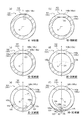
- 6 (a), (b), (c), (d), (e), and (f) are respectively a VI-VI sectional view, a VII-VII sectional view, a VIII-VIII sectional view, and an IX in FIG. -IX sectional drawing, XX sectional drawing, XI-XI sectional drawing.
- the puncture needle 101 includes a main body portion 102 and a distal end portion 103, and defines a hollow portion 110 penetrating from the main body portion 102 to the distal end portion 103.
- the tip portion 103 includes a blade surface 104.
- the blade surface 104 includes a first blade surface portion 105 as a front-side blade surface, and a second blade surface portion 106 and a third blade surface portion 107 as back-side blade surfaces formed on the back side of the front-side blade surface.
- the puncture needle 101 includes a blade surface 104 that has been subjected to backcut processing.
- the configuration of the main body 102 is the same as that of the main body 2 of the puncture needle 1 described above.
- the first blade surface portion 105 includes a first bevel surface 105a, a second bevel surface 105b, and a third bevel surface 105c that are formed of curved surfaces.
- the first bevel surface 105a and the second bevel surface 105b form a blade edge 109 having the needle tip 108 as one end by a ridge line intersecting each other.
- each of the first bevel surface 105a and the second bevel surface 105b is continuous with the third bevel surface 105c on the main body 102 side in the central axis direction A.
- the first bevel surface 105 a and the second bevel surface 105 b define an opening 111 that is one end of the hollow portion 110 on the distal end portion 103 side.
- the third bevel surface 105c is continuous with the outer peripheral surface of the main body 102 on the main body 102 side in the central axis direction A, and is continuous with the first and second bevel surfaces 105a and 105b on the needle tip 108 side in the central axis direction A. is doing.
- the angle of the second bevel surface 105b in the cross section perpendicular to the central axis direction A varies depending on the position in the central axis direction A. .
- the second bevel surface 105b and the third bevel surface 105c are continuous in the central axis direction A, only the outer edge of the second bevel surface 105b is visible.
- the second bevel surface 105b can be visually recognized at the position where the blade edge 109 is formed in the central axis direction A.
- the second bevel surface 105b is configured by a curved surface that extends to twist toward the needle tip 108 from a position continuous with the third bevel surface 105c in the central axis direction A, such as a spiral surface.
- the first bevel surface 105a is also configured by a curved surface extending so as to twist toward the needle tip 108 from a position continuous with the third bevel surface 105c in the central axis direction A in the same manner as the second bevel surface 105b.
- the direction in which the first bevel surface 105a and the second bevel surface 105b are twisted toward the needle tip 108 is opposite.
- the first bevel surface 105a and the second bevel surface 105b are set to one imaginary plane including the central axis O of the main body 102, the first bevel surface 105a and the second bevel surface 105b become centered toward the needle tip 108 side in the central axis direction A. It is composed of a curved surface in which an angle ⁇ with respect to the one virtual plane in a cross section orthogonal to the axial direction A gradually decreases. That is, the puncture needle 101 is a puncture needle that can define such one virtual plane.
- the puncture needle 101 has one plane that can be defined as the “virtual plane” described above.
- the above-mentioned “virtual plane” can be set to the center plane X including the center axis O and the needle tip 108, and the first bevel surface 105a and the second bevel surface 105b are both In the central axis direction A, it is composed of a curved surface in which the angle ⁇ with respect to the central plane X in the cross section orthogonal to the central axis direction A gradually decreases toward the needle tip 108 side.
- the center plane X is a plane including not only the needle tip 108 but also the blade edge 109 and a blade edge 123 described later.
- first bevel surface 105a and the second bevel surface 105b move toward the needle tip 108 side in the central axis direction A, the angle ⁇ with respect to the central plane X in the cross section orthogonal to the central axial direction A gradually decreases.
- one of the first bevel surface 105a and the second bevel surface 105b is configured by such a curved surface, and the other is configured by a curved surface having a flat surface or another surface shape. May be.
- both the first bevel surface 105a and the second bevel surface 105b are curved surfaces in which the angle ⁇ with respect to the central plane X in the cross section orthogonal to the central axial direction A gradually decreases as the direction toward the needle tip 108 in the central axial direction A is increased. If configured, it is possible to easily realize the first blade surface portion 105 in which a ridge line (junction) that can be puncture resistance is not formed between the first and second bevel surfaces 105a and 105b and the third bevel surface 105c. it can.
- the third bevel surface 105c is formed of a convex curved surface that is continuous with the first bevel surface 105a and the second bevel surface 105b. Specifically, the third bevel surface 105c is a convex curved surface that is inclined so that the side view in FIG. 5B approaches the central axis O as it approaches the needle tip 108 in the central axis direction A.
- the angle ⁇ with respect to the central plane X in the cross section orthogonal to the direction A is substantially constant regardless of the position in the central axis direction A.
- the third bevel surface 105 c is a tip side portion 140 a that is continuous with the first bevel surface 105 a and the second bevel surface 105 b on the needle tip 108 side in the central axis direction A.
- a proximal end side portion 140b that is continuous with the main body portion 102 side of the distal end side portion 140a in the central axis direction A.
- the distal end side portion 140a and the proximal end side portion 140b are configured by convex curved surfaces having different curvatures in a side view (see FIGS. 4B and 5B).
- both of the distal end side portion 140a and the proximal end side portion 140b are configured by curved surfaces in which the angle ⁇ with respect to the central plane X in the cross section orthogonal to the central axial direction A is substantially constant regardless of the position in the central axial direction A. Yes. And between the 1st bevel surface 105a and the 2nd bevel surface 105b, and the front end side part 140a, and between the front end side part 140a and the base end side part 140b, it continues smoothly so that a ridgeline may not be formed. .
- the puncture needle 101 has a distal end side portion 140a and a proximal end side portion 140b having different curvatures in a side view (see FIGS. 4B and 5B), and continues in the central axis direction A.
- a ridge line serving as a piercing resistance is not formed between the first and second bevel surfaces 105a and 105b and the third bevel surface 105c. That is, the distal end side portion 140a of the third bevel surface 105c is a connection curved surface for smoothly connecting the first and second bevel surfaces 105a and 105b and the proximal end side portion 140b of the third bevel surface 105c.
- the curvature in the side view is configured to be larger than the curvature of the base end side portion 140b.
- the distal end side portion 140a includes a first connection curved surface 130a positioned between the first bevel surface 105a and the proximal end side portion 140b in the central axis direction A.
- the second connecting curved surface 130b is located between the second bevel surface 105b and the base end side portion 140b in the central axis direction A.
- the first bevel surface 105a is smoothly connected to the proximal end side portion 140b via the first connection curved surface 130a of the distal end side portion 140a
- the second bevel surface 105b is connected to the first bevel surface 105a of the distal end side portion 140a.
- the base end side portion 140b is smoothly connected via the two connection curved surface 130b. 4A and 4D, lines drawn between the first bevel surface 105a and the second bevel surface 105b and the distal end side portion 140a, and the distal end side portion 140a and the proximal end side.
- the line drawn between the portion 140b simply means a boundary line.
- both the distal end side portion 140a and the proximal end side portion 140b of the third bevel surface 105c are inclined so as to gradually approach the central axis O toward the needle tip 108 side in the central axial direction A.
- the inclination angle of 140a and the base end side portion 140b with respect to the central axis direction A is larger than the inclination angle of the outer wall of the main body 102 with respect to the central axis direction A in the cross section including the entire central axis O.
- the “inclination angle with respect to the central axis direction of the distal end side portion” here refers to the third bevel surface including the entire central axis. In the cross-section passing through the upper tip side portion, it means an angle formed by a tangent line at an arbitrary point on the tip side portion of the third bevel surface with the central axis. Further, the “inclination angle of the base end side portion with respect to the central axis direction” is an arbitrary value on the base end side portion of the third bevel surface in a cross section including the entire central axis and passing through the base end side portion on the third bevel surface. The tangent at this point means the angle formed with the central axis.
- the outer diameter of the cylindrical member constituting the puncture needle 101 is uniform regardless of the position in the central axis direction A, and the outer wall of the cylindrical member is the center when viewed in a cross section including the entire central axis O. It extends in the axial direction A. Therefore, as long as the distal end side portion 140a and the proximal end side portion 140b of the third bevel surface 105c are inclined with respect to the central axis direction A, the inclination angle of the distal end side portion 140a and the proximal end side portion 140b is the main body. It becomes larger than the inclination angle of the outer wall of the portion 102.
- the distal end side portion 140a of the third bevel surface 105c is configured not only to be inclined with respect to the central axis direction A but also to be inclined with respect to the outer wall of the main body 102 in a cross section including the entire central axis O.
- the 2nd blade surface part 106 and the 3rd blade surface part 107 are center axis line as it goes to the needle tip 108 side in the central axis direction A like the 2nd blade surface part 6 and the 3rd blade surface part 7 of the puncture needle 1 mentioned above. It is composed of a curved surface in which an angle ⁇ with respect to the central plane X in a cross section orthogonal to the direction A gradually increases.
- the second blade surface portion 106 is formed on the back side of the first bevel surface 105a, and the third blade surface portion 107 is formed on the back side of the second bevel surface 105b. Further, the second blade surface portion 106 and the third blade surface portion 107 form a blade edge 123 having the needle tip 108 as one end by a ridge line intersecting with each other on the needle tip 108 side in the central axis direction A.
- first bevel surface 105a and the second blade surface portion 106 form a blade edge 124 having the needle tip 108 as one end by a ridge line intersecting each other. More specifically, the blade edge 124 is configured by a ridge formed by the outer edge of the first bevel surface 105 a and the outer edge of the second blade surface portion 106.
- the second bevel surface 105b and the third blade surface portion 107 form a blade edge 125 having the needle tip 108 as one end by a ridge line intersecting each other. More specifically, the blade edge 125 is configured by a ridge formed by the outer edge of the second bevel surface 105 b and the outer edge of the third blade surface portion 107.
- a blade edge 123 formed by a ridge line where the second blade surface portion 106 and the third blade surface portion 107 intersect with each other will be referred to as a “first blade edge 123”, and the first bevel surface 105a and the first blade edge portion 105a.
- a blade edge 124 formed by a ridge line intersecting the two blade surface portions 106 is referred to as a “second blade edge 124”, and a blade edge formed by a ridge line intersecting the second bevel surface 105 b and the third blade surface portion 107.
- blade edge 125 is referred to as a “third blade edge 125”, and a blade edge 109 formed by a ridge line where the first bevel surface 105a and the second bevel surface 105b intersect is referred to as a “fourth blade edge 109”.
- the puncture needle 101 includes the first blade surface portion 105 as the front-side blade surface, and the second blade surface portion 106 and the third blade surface portion 107 as the back-side blade surface.
- the tip 108 can be sharpened, and the piercing resistance in the vicinity of the needle tip 108 can be reduced.
- the 2nd blade surface part 106 and the 3rd blade surface part 107 are comprised by the curved surface from which the angle (gamma) with respect to the center plane X in the cross section orthogonal to the center axis direction A increases gradually toward the needle tip 108 side in the center axis direction A.
- the vicinity of the needle tip 108 can be sharpened, and piercing resistance can occur between the second blade surface portion 106 and the third blade surface portion 107 and the outer peripheral surface of the cylindrical member constituting the puncture needle 101. It is easy to realize a configuration in which no ridge line (junction) is formed.
- metal materials such as stainless steel, aluminum or an aluminum alloy, titanium, or a titanium alloy, can be used.
- FIG. 6A shows a VI-VI cross section of FIG. 5, that is, a cross section passing through the base end side portion 140b of the third bevel surface 105c and orthogonal to the central axis direction A.
- the angle ⁇ 1 with respect to the center plane X of the base end side portion 140b in the VI-VI cross section of FIG. 5 is about 90 degrees
- the angle ⁇ with respect to the center plane X of the base end side portion 140b is 5 is about 90 degrees irrespective of the position in the central axis direction A as well as the VI-VI cross section of FIG.
- the base end side portion 140b of the third bevel surface 105c extends linearly in a direction orthogonal to the central plane X in a cross section orthogonal to the central axis direction A, as shown in FIG. is doing.
- FIG. 6B shows a VII-VII cross section of FIG. 5, that is, a cross section that passes through the distal end side portion 140a of the third bevel surface 105c and is orthogonal to the central axis direction A.
- the angle ⁇ 2 with respect to the center plane X of the tip side portion 140a in the VII-VII cross section of FIG. 5 is about 90 degrees
- the angle ⁇ with respect to the center plane X of the tip side portion 140a is It is about 90 degrees regardless of the position in the central axis direction A as well as the VII-VII cross section.
- the tip side portion 140a of the third bevel surface 105c extends linearly in a direction orthogonal to the central plane X in a cross section orthogonal to the central axis direction A, as shown in FIG. ing.
- the boundary line between the distal end side portion 140a and the proximal end side portion 140b on the third bevel surface 105c is indicated by a two-dot chain line. ing.
- FIG. 6C is a cross-sectional view taken along the line VIII-VIII in FIG. 5, that is, the center at the position where the first bevel surface 105a and the second bevel surface 105b are connected to the tip side portion 140a of the third bevel surface 105c.
- the cross section orthogonal to the axial direction A is shown.
- the angle ⁇ 3 with respect to the center plane X of each of the first bevel surface 105a and the second bevel surface 105b in the VIII-VIII cross section of FIG. 5 is about 90 degrees.
- the line extends linearly in a direction orthogonal to the central plane X. That is, the first bevel surface 105a and the second bevel surface 105b are smoothly connected without forming a ridge line with the distal end side portion 140a.
- FIG. 6D is a cross-sectional view taken along the line IX-IX in FIG. 5, that is, the position where the first bevel surface 105a and the second bevel surface 105b are formed in the central axis direction A, and the second blade surface portion 106 and A cross section perpendicular to the central axis direction A at a position where the three blade surface portions 107 are not formed is shown.
- the angle ⁇ 4 with respect to the center plane X of each of the first bevel surface 105a and the second bevel surface 105b in the IX-IX cross section of FIG. 5 is an acute angle smaller than the angle ⁇ 3.
- the first bevel surface 105a, the second bevel surface 105b, and the tip side portion 140a of the third bevel surface 105c are disposed.
- the boundary line is indicated by a two-dot chain line.
- FIG. 6E shows the XX cross-section of FIG. 5, that is, the position where the first bevel surface 105a, the second bevel surface 105b, the second blade surface portion 106, and the third blade surface portion 107 are formed in the central axis direction A. And the cross section orthogonal to the central axis direction A in the position where the opening 111 exists in the central axis direction A is shown. In other words, FIG. 6E shows a position where the first blade edge 123 and the fourth blade edge 109 are not formed in the central axis direction A, and the second blade edge 124 and the third blade edge 125 are formed. It is a cross section orthogonal to the central axis direction A at the position where it is made. As shown in FIG.
- the angle ⁇ 5 with respect to the center plane X of each of the first bevel surface 105a and the second bevel surface 105b in the XX cross section of FIG. 5 is smaller than the angle ⁇ 3 and smaller than ⁇ 4. It is an acute angle.
- the second blade surface portion 106 and the third blade surface portion 107 are formed in the XX cross section of FIG. 5, and the second blade surface portion 106 and the third blade surface portion 107 are formed as shown in FIG. In the cross-sectional view of (e), it extends linearly at a predetermined acute angle ⁇ 5 with respect to the central plane X.
- FIG. 6F is a cross-sectional view taken along the line XI-XI in FIG. 5, that is, at the position where the first blade edge 123, the second blade edge 124, the third blade edge 125, and the fourth blade edge 109 are formed.
- the cross section orthogonal to the axial direction A is shown.
- the angle ⁇ 6 with respect to the center plane X of each of the first bevel surface 105a and the second bevel surface 105b in the XI-XI cross section in FIG. 5 is smaller than the angle ⁇ 3 and from ⁇ 4.
- the angle ⁇ 6 of the second blade surface portion 106 and the third blade surface portion 107 in the XI-XI cross section of FIG. 5 with respect to the center plane X is an acute angle larger than the angle ⁇ 5. is there.
- each of the first bevel surface 105a and the second bevel surface 105b is a straight line in a cross-sectional view orthogonal to the central axis direction A, and the angle ⁇ with respect to the central plane X in the cross section orthogonal to the central axis direction A is In the central axis direction A, it gradually decreases toward the needle tip 108 side (approaching the needle tip 108) (see FIGS. 6C to 6F).
- each of the second blade surface portion 106 and the third blade surface portion 107 is a straight line in a cross-sectional view orthogonal to the central axis direction A, and the angle ⁇ with respect to the central plane X in the cross section orthogonal to the central axis direction A is In the central axis direction A, it gradually increases toward the needle tip 108 side (approaching the needle tip 108) (see FIGS. 6 (e) and 6 (f)).
- 6C to 6F show the angles ⁇ 3 to ⁇ 6 with respect to the central plane X of the second bevel surface 105b, respectively, the angle with respect to the central plane X of the first bevel surface 105a is also the second bevel surface 105b.
- This is the same as the angles ⁇ 3 to ⁇ 6 of the surface 105b.
- 6E and 6F show the angles ⁇ 5 and ⁇ 6 with respect to the center plane X of the third blade surface portion 107, but the angle of the second blade surface portion 106 with respect to the center plane X is also the third angle. It is the same as the angles ⁇ 5 and ⁇ 6 of the blade surface portion 107. Further, the four cross sections in FIGS.
- 6C to 6F are used for illustrative purposes to show the magnitude relationship between the angles ⁇ 3 to ⁇ 6 and the magnitude relationship between the angles ⁇ 5 and ⁇ 6.
- the magnitude relationship between the angles ⁇ and ⁇ is not established for only one cross section.
- both the second blade surface portion 106 and the third blade surface portion 107 are angled with respect to the central plane X in the cross section orthogonal to the central axial direction A as they go toward the needle tip 108 side in the central axial direction A. It is composed of a curved surface in which ⁇ gradually increases, but either one of the second blade surface portion 106 and the third blade surface portion 107 is composed of such a curved surface, and the other is composed of a curved surface having a flat surface or another surface shape. You may make it do.
- the puncture needle according to the present invention can be realized by various specific configurations, and is not limited to the configuration described above.
- the puncture needle according to the present invention is not limited to the above-described embodiment, and can be changed without departing from the gist of the invention described in the claims.
- FIG. 8 is a flowchart showing a method of manufacturing the puncture needle 1 as the present embodiment.
- the manufacturing method of the puncture needle 1 includes a cylindrical member acquisition step S1 for obtaining a cylindrical member as a hollow rod-shaped member among the rod-shaped members, which is in a state before the puncture needle 1 is attached, A blade surface forming step S2 for forming a puncture needle 1 by forming a blade surface 4 (see FIGS. 1 and 2) on at least one end of the shaped member.
- polishing process S3 which grind
- the cylindrical member acquisition step S1 can be performed by various known methods. For example, a receiving step S1-1 for receiving a strip-shaped metal plate material into a press molding machine, and the press molding machine continuously removes the plate material. Press forming step S1-2 to obtain a plurality of pipes that are partly connected to the plate material, and a joining step S1-3 for bonding the joints of the pipes by welding or an adhesive, A straightening step S1-4 for correcting the shape of the tubular body so that the central axis of the tubular body is substantially straight, and a tubular member that is in a state before the puncture needle 101 is bladed by separating the tubular body from the plate material Separating step S1-5 to obtain
- the blade surface forming step S2 includes a first blade surface portion forming step S2-1 for forming the first blade surface portion 5 (see FIG. 1, FIG. 2, etc.) and a third blade surface portion 7 (see FIG. 1, FIG. 2, etc.).
- FIG. 9 is a schematic diagram showing an outline of a method of forming the first to third blade surface portions 5 to 7 in the blade surface forming step S2, and
- FIG. 9A is a diagram illustrating the first blade surface portion forming step S2-1.
- FIG. 9 (b) shows a method of forming the third blade surface portion 7 in the third blade surface portion forming step S2-2
- FIG. 9 (c) shows a method of forming the second blade surface portion.
- a method of forming the second blade surface portion 6 in step S2-3 is shown.
- the first blade surface portion 5 is formed at the end of the cylindrical member 50 by grinding with a grindstone.
- the cylindrical member 50 is not rotated, and the tilt angle of the central axis Y of the cylindrical member 50 with respect to the grinding surface of the grindstone is not changed.
- the first blade surface portion 5 can also be formed in the press molding step S1-2 in the above-described cylindrical member acquisition step S1. Further, the first blade surface portion 5 can be formed by wire cutting or the like instead of grinding by a grindstone.
- 9A to 9C the grinding surface of the rotating grindstone is indicated by a two-dot chain line “G”.
- the grinding surface G of the grindstone is moved while moving the grindstone rotating at high speed.
- the cylindrical member 50 acquired by cylindrical member acquisition process S1 is slidably contacted (plan geosilation grinding), and the 3rd blade surface part 7 and the 2nd blade surface part 6 are formed.
- the cylindrical member 50 is rotated about the central axis Y of the cylindrical member 50 and the cylindrical member 50 is rotated.
- a third blade surface portion as a blade surface portion constituted by a curved surface is obtained by sliding the back side of the first blade surface portion 5 against the grinding surface G of the grindstone while changing the tilt angle of the central axis Y with respect to the grinding surface G of the grindstone. 7 and the second blade surface portion 6 are formed.
- the grinding surface G of the grindstone and the first blade surface portion 5 are also affected by the rotation of the cylindrical member 50 and the change in the inclination angle.
- a grindstone is moved so that it may approach the cylindrical member 50 so that sliding contact with the back side may be maintained (refer arrow "N1" of Drawing 9 (b) and Drawing 9 (c)).
- the cylindrical member 50 is rotated in one direction about the central axis Y of the cylindrical member 50 (see the arrow “L1” in FIG. 9B). While changing the tilt angle of the central axis Y of the cylindrical member 50 with respect to the grinding surface G of the grindstone in one tilt direction (see the arrow “M1” in FIG. 9B), the back side of the first blade surface portion 5 is It can be carried out by making sliding contact with the grinding surface G of the grindstone.
- the third blade surface portion forming step S2-2 the third blade surface portion 7 is formed and the third blade edge 16 is formed.
- the rotational speed and the tilting speed of the cylindrical member 50 can be constant or can be varied according to the grinding position. It is preferable to set a constant speed so that a ridge line (junction) is not easily formed.
- the cylindrical member 50 is reset to the position and posture at which the second blade surface portion forming step S2-3 is started, and after the resetting is completed, the second blade surface portion forming step S2-3. Can start.
- the second blade surface portion forming step S2-3 is centered on the central axis Y of the cylindrical member 50 and is opposite to the one direction in the third blade surface portion forming step S2-2 (see the arrow “L2” in FIG. 9C). And the tilt angle of the central axis Y of the cylindrical member 50 with respect to the grinding surface G of the grindstone is the same as the one tilt direction in the third blade surface portion forming step S2-2.
- the position on the back side of the first blade surface portion 5 and adjacent to the third blade surface portion 7 in the circumferential direction is slid onto the grinding surface G of the grindstone while changing in the direction (see the arrow “M1” in FIG. 9C). This can be done by contact.
- the second blade surface portion forming step S2-3, the second blade surface portion 6 is formed, and the first blade edge 23 and the second blade edge 15 are formed.
- the rotation speed and the tilting speed of the cylindrical member 50 may be constant, depending on the grinding position. However, it is preferable to set a constant speed so that a ridge line (junction) that becomes a piercing resistance is not easily formed.
- the end of the tubular member 50 is slidably brought into contact with the grinding surface G of the grindstone, thereby forming a curved surface.
- the configured third blade surface portion 7 and second blade surface portion 6 can be formed.
- the end of the cylindrical cylindrical member is pressed in the cylindrical member acquisition step S1 or immediately before the first blade surface portion formation step S2-1, thereby cutting the blade.
- the cross-sectional outer shape of one end where the surface 154 is formed can be made into a substantially elliptical shape.
- the subsequent steps are the same as those described above.
- a solid rod-shaped member is formed by a known solid rod-shaped member acquisition step that forms a solid rod-shaped member.
- the blade surface 4 ′ can be formed on one end of the solid bar-like member by the same method as in the blade surface forming step S2 described above.
- the present invention relates to a medical puncture needle and a method for manufacturing the puncture needle.
Landscapes
- Health & Medical Sciences (AREA)
- Engineering & Computer Science (AREA)
- Life Sciences & Earth Sciences (AREA)
- Public Health (AREA)
- Animal Behavior & Ethology (AREA)
- Veterinary Medicine (AREA)
- Biomedical Technology (AREA)
- Heart & Thoracic Surgery (AREA)
- General Health & Medical Sciences (AREA)
- Vascular Medicine (AREA)
- Anesthesiology (AREA)
- Hematology (AREA)
- Mechanical Engineering (AREA)
- Surgery (AREA)
- Molecular Biology (AREA)
- Medical Informatics (AREA)
- Pathology (AREA)
- Nuclear Medicine, Radiotherapy & Molecular Imaging (AREA)
- Infusion, Injection, And Reservoir Apparatuses (AREA)
Abstract
Cette aiguille de ponction médicale comprend : une partie d'extrémité de pointe comprenant une pointe d'aiguille ; et une partie de corps principal en forme de tige qui est contiguë à la partie d'extrémité de pointe La partie d'extrémité de pointe a une surface de lame. La surface de lame comprend : une première partie de surface de lame qui est inclinée par rapport à l'axe central de la partie de corps principal, et qui s'étend jusqu'à la pointe de l'aiguille ; et une seconde partie de surface de lame qui est formée sur le côté arrière de la première partie de surface de lame En supposant qu'il existe un plan virtuel comprenant l'axe central de la partie de corps principal, la seconde partie de surface de lame est constituée par une surface incurvée dont l'angle par rapport au plan virtuel selon une coupe transversale orthogonale par rapport à la direction de l'axe central augmente progressivement vers le coté de pointe de l'aiguille le long de la direction de l'axe central.
Priority Applications (4)
| Application Number | Priority Date | Filing Date | Title |
|---|---|---|---|
| CN202010842521.7A CN111973842B (zh) | 2015-07-30 | 2016-07-20 | 医疗用穿刺针和穿刺针的制造方法 |
| JP2017531011A JP6744864B2 (ja) | 2015-07-30 | 2016-07-20 | 医療用の穿刺針 |
| CN201680044501.7A CN107847670B (zh) | 2015-07-30 | 2016-07-20 | 医疗用穿刺针和穿刺针的制造方法 |
| US15/883,638 US10722264B2 (en) | 2015-07-30 | 2018-01-30 | Medical puncture needle and method for manufacturing puncture needle |
Applications Claiming Priority (2)
| Application Number | Priority Date | Filing Date | Title |
|---|---|---|---|
| JP2015-151313 | 2015-07-30 | ||
| JP2015151313 | 2015-07-30 |
Related Child Applications (1)
| Application Number | Title | Priority Date | Filing Date |
|---|---|---|---|
| US15/883,638 Continuation US10722264B2 (en) | 2015-07-30 | 2018-01-30 | Medical puncture needle and method for manufacturing puncture needle |
Publications (1)
| Publication Number | Publication Date |
|---|---|
| WO2017017936A1 true WO2017017936A1 (fr) | 2017-02-02 |
Family
ID=57884156
Family Applications (1)
| Application Number | Title | Priority Date | Filing Date |
|---|---|---|---|
| PCT/JP2016/003399 Ceased WO2017017936A1 (fr) | 2015-07-30 | 2016-07-20 | Aiguille de ponction médicale et procédé de fabrication d'aiguille de ponction |
Country Status (4)
| Country | Link |
|---|---|
| US (1) | US10722264B2 (fr) |
| JP (2) | JP6744864B2 (fr) |
| CN (2) | CN111973842B (fr) |
| WO (1) | WO2017017936A1 (fr) |
Cited By (6)
| Publication number | Priority date | Publication date | Assignee | Title |
|---|---|---|---|---|
| WO2018169032A1 (fr) * | 2017-03-16 | 2018-09-20 | テルモ株式会社 | Ensemble cathéter |
| KR20210049052A (ko) * | 2018-09-06 | 2021-05-04 | 주식회사 플라워메디칼 | 생검용 니들셋 |
| CN113143524A (zh) * | 2021-04-13 | 2021-07-23 | 王伟 | 一种用于构建微创兔膝关节炎模型的穿刺系统 |
| JP2022512504A (ja) * | 2018-12-17 | 2022-02-04 | エスエイチエル・メディカル・アーゲー | 医療ベベルニードル |
| JP2022115128A (ja) * | 2021-01-28 | 2022-08-09 | Useful株式会社 | 注射針の針先向き位置合わせ装置 |
| US12138434B2 (en) | 2018-03-19 | 2024-11-12 | Terumo Kabushiki Kaisha | Puncture needle and catheter assembly |
Families Citing this family (9)
| Publication number | Priority date | Publication date | Assignee | Title |
|---|---|---|---|---|
| BR112016018570B1 (pt) * | 2014-02-12 | 2022-08-30 | Gyroscope Therapeutics Limited | Aparelho para a liberação de agente terapêutico em um olho |
| MX2020001390A (es) * | 2017-08-04 | 2020-03-20 | Becton Dickinson Co | Dispositivo de insercion de aguja y cateter. |
| US11439386B2 (en) * | 2017-11-15 | 2022-09-13 | Winter Innovations, Inc. | Interlocking two-part sewing needle for double loop stitching |
| CN110354334B (zh) * | 2019-07-24 | 2024-11-26 | 河南曙光汇知康生物科技股份有限公司 | 输液港用穿刺针针头及其制成的输液港用穿刺针 |
| CN114681019B (zh) * | 2020-12-30 | 2024-07-02 | 杭州德晋医疗科技有限公司 | 一种心内膜注射装置及心内膜注射系统 |
| EP4284477A4 (fr) * | 2021-01-29 | 2025-01-01 | Pierce Holdings, FLP | Cathéter intravasculaire et son procédé d'utilisation |
| CN115252116A (zh) * | 2022-08-14 | 2022-11-01 | 南京瑞波医学科技有限公司 | 一种微型消融针头 |
| US20250058080A1 (en) | 2023-08-17 | 2025-02-20 | Thomas Mowrey | Vascular Access Devices Having Curves |
| CN118505955B (zh) * | 2024-05-14 | 2026-02-10 | 广州市微眸医疗器械有限公司 | 一种器械震颤检测方法、系统及可读存储介质 |
Citations (4)
| Publication number | Priority date | Publication date | Assignee | Title |
|---|---|---|---|---|
| JP2008154843A (ja) * | 2006-12-25 | 2008-07-10 | Nisshin Kogu Kk | 注射針 |
| JP2008528222A (ja) * | 2005-02-03 | 2008-07-31 | ヴィゴン | 穿刺先端部とカテーテルチューブの改良 |
| JP2012115336A (ja) * | 2010-11-29 | 2012-06-21 | Nipro Corp | 医療用中空針および医療用中空針の製造方法 |
| JP2014004249A (ja) * | 2012-06-26 | 2014-01-16 | Unique Medical Co Ltd | 注射針および電極針 |
Family Cites Families (16)
| Publication number | Priority date | Publication date | Assignee | Title |
|---|---|---|---|---|
| US3308822A (en) * | 1964-04-02 | 1967-03-14 | Loretta Fontano | Hypodermic needle |
| US3448740A (en) * | 1966-06-24 | 1969-06-10 | Frank H J Figge | Nonheel shaving hypodermic needle |
| JP3311920B2 (ja) * | 1995-04-28 | 2002-08-05 | 嘉邦 斎藤 | 医療用中空針 |
| US5820609A (en) * | 1995-04-28 | 1998-10-13 | Saito; Yoshikuni | Medical hollow needle and a method of producing thereof |
| US5752942A (en) * | 1996-06-20 | 1998-05-19 | Becton Dickinson And Company | Five beveled point geometry for a hypodermic needle |
| JP3492543B2 (ja) * | 1999-03-15 | 2004-02-03 | 金子工業有限会社 | 注射針とその製造方法 |
| JP4025567B2 (ja) * | 2002-03-29 | 2007-12-19 | テルモ株式会社 | 注射針 |
| JP4121309B2 (ja) * | 2002-05-31 | 2008-07-23 | 富士フイルム株式会社 | ネガ型レジスト組成物 |
| WO2007066772A1 (fr) * | 2005-12-08 | 2007-06-14 | Arkray, Inc. | Aiguille d'insertion et lancette munie de celle-ci |
| US20090318946A1 (en) * | 2006-06-02 | 2009-12-24 | Yuji Tamesada | Pricking Needle and Lancet Having The Same |
| CN101610803A (zh) * | 2006-12-21 | 2009-12-23 | Ssb技术有限公司 | 针尖 |
| JP2008154842A (ja) * | 2006-12-25 | 2008-07-10 | Nisshin Kogu Kk | 注射針 |
| EP2272438B1 (fr) * | 2008-04-30 | 2013-12-18 | MANI Inc. | Aiguille de suture médicale |
| JP5653655B2 (ja) * | 2010-06-02 | 2015-01-14 | 旭化成メディカル株式会社 | 穿刺針及び血管表面切痕形成器具 |
| CN104721911A (zh) * | 2015-03-05 | 2015-06-24 | 倪治法 | 无损伤防脱落穿刺针 |
| EP3363482B1 (fr) * | 2015-07-30 | 2025-11-19 | Terumo Kabushiki Kaisha | Aiguille de ponction médicale et procédé de production d'aiguille de ponction |
-
2016
- 2016-07-20 WO PCT/JP2016/003399 patent/WO2017017936A1/fr not_active Ceased
- 2016-07-20 JP JP2017531011A patent/JP6744864B2/ja active Active
- 2016-07-20 CN CN202010842521.7A patent/CN111973842B/zh active Active
- 2016-07-20 CN CN201680044501.7A patent/CN107847670B/zh active Active
-
2018
- 2018-01-30 US US15/883,638 patent/US10722264B2/en active Active
-
2020
- 2020-07-31 JP JP2020130350A patent/JP2020185428A/ja active Pending
Patent Citations (4)
| Publication number | Priority date | Publication date | Assignee | Title |
|---|---|---|---|---|
| JP2008528222A (ja) * | 2005-02-03 | 2008-07-31 | ヴィゴン | 穿刺先端部とカテーテルチューブの改良 |
| JP2008154843A (ja) * | 2006-12-25 | 2008-07-10 | Nisshin Kogu Kk | 注射針 |
| JP2012115336A (ja) * | 2010-11-29 | 2012-06-21 | Nipro Corp | 医療用中空針および医療用中空針の製造方法 |
| JP2014004249A (ja) * | 2012-06-26 | 2014-01-16 | Unique Medical Co Ltd | 注射針および電極針 |
Cited By (14)
| Publication number | Priority date | Publication date | Assignee | Title |
|---|---|---|---|---|
| WO2018169032A1 (fr) * | 2017-03-16 | 2018-09-20 | テルモ株式会社 | Ensemble cathéter |
| JPWO2018169032A1 (ja) * | 2017-03-16 | 2020-01-23 | テルモ株式会社 | カテーテル組立体 |
| US11904115B2 (en) | 2017-03-16 | 2024-02-20 | Terumo Kabushiki Kaisha | Catheter assembly |
| JP7049315B2 (ja) | 2017-03-16 | 2022-04-06 | テルモ株式会社 | カテーテル組立体 |
| US11318284B2 (en) | 2017-03-16 | 2022-05-03 | Terumo Kabushiki Kaisha | Catheter assembly |
| US12138434B2 (en) | 2018-03-19 | 2024-11-12 | Terumo Kabushiki Kaisha | Puncture needle and catheter assembly |
| KR20210049052A (ko) * | 2018-09-06 | 2021-05-04 | 주식회사 플라워메디칼 | 생검용 니들셋 |
| KR102384813B1 (ko) * | 2018-09-06 | 2022-04-08 | 주식회사 플라워메디칼 | 생검용 니들셋 |
| JP7284267B2 (ja) | 2018-12-17 | 2023-05-30 | エスエイチエル・メディカル・アーゲー | 医療ベベルニードル |
| JP2022512504A (ja) * | 2018-12-17 | 2022-02-04 | エスエイチエル・メディカル・アーゲー | 医療ベベルニードル |
| US11969585B2 (en) | 2018-12-17 | 2024-04-30 | Shl Medical Ag | Medical bevel needle |
| JP2022115128A (ja) * | 2021-01-28 | 2022-08-09 | Useful株式会社 | 注射針の針先向き位置合わせ装置 |
| JP7822541B2 (ja) | 2021-01-28 | 2026-03-03 | Useful株式会社 | 注射針の針先向き位置合わせ装置 |
| CN113143524A (zh) * | 2021-04-13 | 2021-07-23 | 王伟 | 一种用于构建微创兔膝关节炎模型的穿刺系统 |
Also Published As
| Publication number | Publication date |
|---|---|
| JP2020185428A (ja) | 2020-11-19 |
| CN111973842A (zh) | 2020-11-24 |
| JPWO2017017936A1 (ja) | 2018-05-17 |
| CN107847670B (zh) | 2020-09-04 |
| US20180153579A1 (en) | 2018-06-07 |
| JP6744864B2 (ja) | 2020-08-19 |
| CN111973842B (zh) | 2022-12-09 |
| CN107847670A (zh) | 2018-03-27 |
| US10722264B2 (en) | 2020-07-28 |
Similar Documents
| Publication | Publication Date | Title |
|---|---|---|
| JP6744864B2 (ja) | 医療用の穿刺針 | |
| JP6758292B2 (ja) | 医療用の穿刺針 | |
| JP6982157B2 (ja) | 医療用の穿刺針及び穿刺針の製造方法 | |
| CN105939740B (zh) | 医疗用的穿刺针以及穿刺针的制造方法 | |
| TWI734958B (zh) | 穿刺針及導管組合體 | |
| WO1999058176A1 (fr) | Aiguille pour ponction medicale et son procede de production | |
| WO2017017934A1 (fr) | Aiguille de ponction médicale | |
| JP2017080117A (ja) | 医療用穿刺針 | |
| JP7034024B2 (ja) | 医療用の穿刺針 | |
| JP7221928B2 (ja) | 穿刺針 | |
| HK1227778A1 (en) | Puncture needle for medical use, and method for manufacturing puncture needle |
Legal Events
| Date | Code | Title | Description |
|---|---|---|---|
| 121 | Ep: the epo has been informed by wipo that ep was designated in this application |
Ref document number: 16830042 Country of ref document: EP Kind code of ref document: A1 |
|
| ENP | Entry into the national phase |
Ref document number: 2017531011 Country of ref document: JP Kind code of ref document: A |
|
| NENP | Non-entry into the national phase |
Ref country code: DE |
|
| 122 | Ep: pct application non-entry in european phase |
Ref document number: 16830042 Country of ref document: EP Kind code of ref document: A1 |