WO2017017972A1 - Système de transmission de données d'image - Google Patents
Système de transmission de données d'image Download PDFInfo
- Publication number
- WO2017017972A1 WO2017017972A1 PCT/JP2016/052163 JP2016052163W WO2017017972A1 WO 2017017972 A1 WO2017017972 A1 WO 2017017972A1 JP 2016052163 W JP2016052163 W JP 2016052163W WO 2017017972 A1 WO2017017972 A1 WO 2017017972A1
- Authority
- WO
- WIPO (PCT)
- Prior art keywords
- unit
- communication
- digital data
- control code
- image data
- Prior art date
- Legal status (The legal status is an assumption and is not a legal conclusion. Google has not performed a legal analysis and makes no representation as to the accuracy of the status listed.)
- Ceased
Links
Images




Classifications
-
- H—ELECTRICITY
- H04—ELECTRIC COMMUNICATION TECHNIQUE
- H04L—TRANSMISSION OF DIGITAL INFORMATION, e.g. TELEGRAPHIC COMMUNICATION
- H04L1/00—Arrangements for detecting or preventing errors in the information received
- H04L1/004—Arrangements for detecting or preventing errors in the information received by using forward error control
- H04L1/0056—Systems characterized by the type of code used
- H04L1/0061—Error detection codes
-
- A—HUMAN NECESSITIES
- A61—MEDICAL OR VETERINARY SCIENCE; HYGIENE
- A61B—DIAGNOSIS; SURGERY; IDENTIFICATION
- A61B1/00—Instruments for performing medical examinations of the interior of cavities or tubes of the body by visual or photographical inspection, e.g. endoscopes; Illuminating arrangements therefor
- A61B1/04—Instruments for performing medical examinations of the interior of cavities or tubes of the body by visual or photographical inspection, e.g. endoscopes; Illuminating arrangements therefor combined with photographic or television appliances
-
- H—ELECTRICITY
- H04—ELECTRIC COMMUNICATION TECHNIQUE
- H04L—TRANSMISSION OF DIGITAL INFORMATION, e.g. TELEGRAPHIC COMMUNICATION
- H04L1/00—Arrangements for detecting or preventing errors in the information received
- H04L1/004—Arrangements for detecting or preventing errors in the information received by using forward error control
- H04L1/0045—Arrangements at the receiver end
-
- H—ELECTRICITY
- H04—ELECTRIC COMMUNICATION TECHNIQUE
- H04N—PICTORIAL COMMUNICATION, e.g. TELEVISION
- H04N25/00—Circuitry of solid-state image sensors [SSIS]; Control thereof
- H04N25/60—Noise processing, e.g. detecting, correcting, reducing or removing noise
-
- G—PHYSICS
- G06—COMPUTING OR CALCULATING; COUNTING
- G06T—IMAGE DATA PROCESSING OR GENERATION, IN GENERAL
- G06T2210/00—Indexing scheme for image generation or computer graphics
- G06T2210/52—Parallel processing
-
- H—ELECTRICITY
- H04—ELECTRIC COMMUNICATION TECHNIQUE
- H04N—PICTORIAL COMMUNICATION, e.g. TELEVISION
- H04N23/00—Cameras or camera modules comprising electronic image sensors; Control thereof
- H04N23/50—Constructional details
- H04N23/555—Constructional details for picking-up images in sites, inaccessible due to their dimensions or hazardous conditions, e.g. endoscopes or borescopes
-
- H—ELECTRICITY
- H04—ELECTRIC COMMUNICATION TECHNIQUE
- H04N—PICTORIAL COMMUNICATION, e.g. TELEVISION
- H04N23/00—Cameras or camera modules comprising electronic image sensors; Control thereof
- H04N23/56—Cameras or camera modules comprising electronic image sensors; Control thereof provided with illuminating means
Definitions
- the present invention relates to an image data transmission system, and more particularly to an image data transmission system that converts parallel digital data output from an imaging unit into serial digital data and transmits the serial digital data.
- endoscopes equipped with an image sensor for observing a subject have been widely used in the medical field and the industrial field.
- There is also a known technique for constituting an endoscope system which is detachably connected to an endoscope and performs various signal processing related to the endoscope by a signal processing device called a video processor.
- a CMOS image sensor employed in this type of endoscope is a sensor unit (imaging unit) that photoelectrically converts light from an optical system and outputs an electrical signal as image information, and an electrical signal output by the sensor unit.
- an AFE unit that performs noise removal and A / D conversion, and a P / S conversion unit that performs parallel / serial conversion on parallel digital signals output from the AFE unit and transmits them as serial digital data to the outside.
- This 8B10B transmission method is a method of transmitting 8-bit data after converting it to 10-bit data. Specifically, the 8-bit data is encoded into 10-bit word data and transmitted as a set of 8-bit data. is there.
- a synchronization code (K code) is transmitted together with normal video data (D code) in order to find word data breaks at the time of decoding on the receiving side. It has become.
- treatment using an electric knife or the like may be performed in parallel with observation / treatment of a subject with an endoscope.
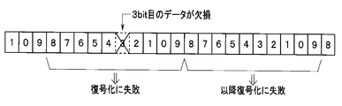
- the electric knife or the like due to the influence of disturbance noise caused by the electric knife or the like, there is a possibility that, for example, data for 1 bit may be missed during the transmission of the serial digital data described above.
- the video data cannot be received correctly because the delimiter position is shifted on the receiving side, and decoding will continue to fail until the synchronization code is received again and the delimiter position is found again. .
- This synchronization code is generally embedded at startup, and is periodically embedded at a rate of 1 per 1V (1 vertical synchronization signal).
- the transmission speed may increase or the transmission speed needs to be increased in order to secure the necessary transmission amount.
- Japanese Patent No. 5548054 describes that if a decoding error occurs on the serial data receiving side, error correction is performed, or data that cannot be corrected still is displayed in surrounding pixels. Interpolation techniques are shown.
- the time until the break position is corrected is shorter than that in a method of waiting for a normal control code, but the receiving side is synchronized with normal data.
- a dedicated circuit for detecting timing is required.
- An object of the present invention is to provide an image data transmission system capable of returning data transmission.
- An image data transmission system is a coding that performs a predetermined coding process on the parallel digital data output from an imaging unit that captures an image of a subject, acquires image data, and outputs parallel digital data.
- a control code insertion unit that instructs to insert a control code at a predetermined timing with respect to the parallel digital data output from the imaging unit when the encoding unit performs the predetermined encoding process;
- a P / S conversion unit that converts the parallel digital data that has been subjected to the predetermined encoding process in the encoding unit into serial digital data and transmits the data, and transmits the image data from the image data transmission device.
- An S / P converter that receives the serial digital data, converts it into parallel digital data, and outputs the parallel digital data;
- a control code detection unit that detects the control code from the parallel digital data that is converted and output by the S / P conversion unit, and conversion by the S / P conversion unit according to the control code detected by the control code detection unit
- a decoding unit that performs a predetermined decoding process on the parallel digital data that is output, and a decoding error detection unit that can detect a decoding error that occurs during the decoding process in the decoding unit;
- An image data receiving device comprising: a communication transmitting unit that transmits notification information related to the detection of the decoding error to the image data transmitting device when the decoding error is detected in the decoding error detecting unit
- the image data transmitting device further includes a communication receiving unit that receives the notification information from the communication transmitting unit, and The code insertion unit, when receiving the notification information in the communication receiving unit, applies the control code at a predetermined timing to the parallel digital data output from the
- FIG. 1 is an external perspective view showing a configuration of an endoscope system that is an image data transmission system according to a first embodiment of the present invention.
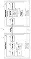
- FIG. 2 is a block diagram showing a schematic configuration of the image data transmission system according to the first embodiment.
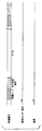
- FIG. 3 is a timing chart showing a transmission state of the video signal when no decoding error occurs in the image data transmission system according to the first embodiment.
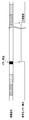
- FIG. 4 is a timing chart showing the transmission state of the video signal when the decoding function is not used in the image data transmission system according to the first embodiment when the control code insertion function according to the present invention is not used. It is.
- FIG. 1 is an external perspective view showing a configuration of an endoscope system that is an image data transmission system according to a first embodiment of the present invention.
- FIG. 2 is a block diagram showing a schematic configuration of the image data transmission system according to the first embodiment.
- FIG. 3 is a timing chart showing a transmission state of the video signal when no decoding error occurs in the image data transmission system according to
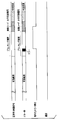
- FIG. 5 is a timing diagram showing how video signal transmission returns to normal using the control code insertion function according to the present invention when a decoding error occurs in the image data transmission system according to the first embodiment. It is a chart.
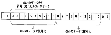
- FIG. 6 is a diagram illustrating a data structure at the time of normal transmission of serial digital data encoded into 8B10B in the image data transmission system according to the first embodiment.
- FIG. 7 is a diagram illustrating an example of a data structure when an error occurs in serial digital data encoded into 8B10B in the image data transmission system according to the first embodiment.
- FIG. 8 is a timing chart showing the transmission state of the video signal when an error occurs during the blanking period in the image data transmission system according to the first modification of the first embodiment.
- FIG. 6 is a diagram illustrating a data structure at the time of normal transmission of serial digital data encoded into 8B10B in the image data transmission system according to the first embodiment.
- FIG. 7 is a diagram illustrating an example of a data structure when an error occurs in serial digital
- FIG. 9 shows the transmission state of the video signal when the control code insertion timing and the start of the next blanking period are close to each other in the image data transmission system according to the second modification of the first embodiment. It is a timing chart.
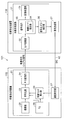
- FIG. 10 is a block diagram showing a schematic configuration of an image data transmission system according to the second embodiment of the present invention.
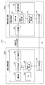
- FIG. 11 is a block diagram showing a schematic configuration of an image data transmission system according to the third embodiment of the present invention.
- FIG. 12 is a block diagram showing a schematic configuration of an image data transmission system according to the fourth embodiment of the present invention.
- FIG. 13 is a timing chart showing signal states of the circuits in the image data transmission system according to the fourth embodiment.
- FIG. 1 is an external perspective view showing a configuration of an endoscope system that is an image data transmission system according to a first embodiment of the present invention
- FIG. 2 shows the configuration of the first embodiment of the present invention. It is the block diagram which showed schematic structure of this image data transmission system (endoscope system).
- an endoscope system is described as an “image data transmission system”
- an endoscope is described as an “image transmitting device”
- a video processor is described as an “image receiving device”. To do.
- an endoscope system 1 that is an image data transmission system captures an in-vivo image of a subject by inserting a distal end portion of an insertion portion 7 into a body cavity of a subject, and the subject image.
- Which outputs the video signal of 2 as serial digital data receives the video signal of the serial digital data output from the endoscope 2, performs predetermined image processing, and supervises the overall operation of the endoscope system 1
- a video processor 3 to be controlled automatically, a light source device 4 that generates illumination light to be emitted from the distal end of the endoscope 2, and a display device 5 that displays an image subjected to image processing in the video processor 3.
- the endoscope 2 includes an image sensor 21 that receives a subject image, photoelectrically converts it into an electrical signal, and performs predetermined signal processing.
- the imaging element 21 is configured by, for example, a CMOS image sensor, and converts the light from the optical system into a sensor unit (imaging unit) 22 that outputs an electrical signal as image information, and the electrical signal output by the imaging unit 22.
- An AFE unit (not shown) that performs noise removal and A / D conversion on the image
- an encoding unit 23 that encodes a parallel digital signal output from the AFE unit by 8B10B
- parallel digital data encoded by the encoding unit 23 A P / S converter 24 for parallel / serial conversion of the data and outputting the serial digital data (serial signal) to the outside, and a code for synchronizing the parallel digital data encoded in the encoding 23 at a predetermined timing (Hereinafter referred to as a control code) a control code insertion unit 25 for instructing insertion, and an imaging unit 22
- a timing generator (TG) 26 for generating various signal processing pulses in the drive timing, AFE unit, encoding unit 23, P / S conversion unit 24,
- the endoscope 2 further receives predetermined decoding error information notified from the video processor 3 side via a dedicated line 41 (decoding sent via the dedicated line 41 as will be described later).
- the error information also has a meaning as a control code insertion instruction to the control code insertion unit 25), and when the decoding error information is received, the control code insertion unit 25 is notified that the information has been received.
- a communication receiving unit 27 is provided.
- the video processor 3 includes a video reception circuit 31 that receives a video signal of serial digital data encoded in 8B10B output from the P / S conversion unit 24 in the endoscope 2 and performs predetermined image processing and the like. .
- the video receiving circuit 31 receives an encoded video signal of serial digital data, serial / parallel converts it and outputs it as parallel digital data to the subsequent stage, and the parallel digital data from the parallel digital data.
- a control code detection unit 34 for detecting a control code; and a decoding process for the encoded parallel digital data including the control code detection unit 34 and based on the control code detected by the control code detection unit 34
- a decoding unit 33 that performs the decoding process, a decoding error detection unit 36 that detects the decoding error when a decoding error occurs when performing the decoding process in the decoding unit 33, and the decoding unit
- an image processing unit 35 for inputting the video signal subjected to the decoding process in 33 and performing a predetermined image process.
- the video processor 3 is further connected to the decoding error detection unit 36, and when the decoding error detection unit 36 detects a decoding error, the video processor 3 transmits the decoding error information to the communication receiving unit 27 in the endoscope 2.
- the communication transmission part 37 which transmits toward is provided.
- the communication transmitter 37 and the communication receiver 27 are connected by a dedicated line 41, and the decoding error information described above is transmitted from the communication transmitter 37 to the communication receiver 27 via the dedicated line 41. And it is transmitted with respect to the control code insertion part 25.
- FIG. 41 the decoding error information described above is transmitted from the communication transmitter 37 to the communication receiver 27 via the dedicated line 41. And it is transmitted with respect to the control code insertion part 25.
- the communication transmitting unit 37 functions to notify the decoding error information to the communication receiving unit 27 in the endoscope 2.
- FIG. 4 is a timing chart showing a transmission state of a video signal when no decoding error occurs in the image data transmission system according to the first embodiment
- FIG. 5 is a timing chart showing the first embodiment
- 6 is a timing chart showing a transmission state of a video signal when a decoding error occurs in the image data transmission system according to the present invention when the control code insertion function according to the present invention is not used.
- FIG. 6 shows how the video signal transmission returns to normal using the control code insertion function according to the present invention when a decoding error occurs in the image data transmission system according to the first embodiment. It is a timing chart.
- the endoscope 2 first outputs an analog electric signal from the imaging unit 22 when the imaging unit 22 images the subject. After that, the electric signal is subjected to noise removal and A / D conversion in the AFE unit, and then the parallel digital signal is encoded by 8B10B in the encoding unit 23 and also encoded in the encoding unit 23.
- the parallel digital data is parallel / serial converted by the P / S converter 24 and output to the outside as serial digital data.
- 8-bit data is encoded into 10-bit word data indicated by 0 to 9 as a set and transmitted to the subsequent stage.
- an instruction of the control code insertion unit 25 instructs the parallel digital data to be displayed in the encoding unit 23.
- a control code for synchronization is inserted into the signal at a predetermined timing.
- control code insertion unit 25 instructs the encoding unit 23 to insert a control code for synchronization according to the timing determined by the timing generator 26.
- FIG. 3 shows an example in which one control code is inserted for each horizontal synchronization signal.
- the S / P converter 32 receives the serial digital data output from the endoscope 2 side, and further receives the received serial digital data. Perform serial / parallel conversion.
- control code detection unit 34 in the decoding unit 33 detects the synchronization control code from the parallel digital data serial / parallel converted by the S / P conversion unit 32 to detect a delimiter position.
- the decoding 33 performs a decoding process on the parallel digital data according to the break position detected by the control code detection unit 34.
- the decoding unit 33 decodes 8-bit data from 10-bit data encoded from 8-bit data.
- the decoding error detection unit 36 does not detect a decoding error as shown in FIG. An “L” level signal indicating that no occurrence has occurred is output.
- the electrical signal output from the imaging unit 22 is encoded by the parallel digital signal 8B10B in the encoding 24 through the AFE unit, and the parallel / serial in the P / S conversion unit 24. It is converted and output as serial digital data.
- the encoding unit 23 determines a predetermined timing, that is, a timing determined by the timing generator 26. In response to this, a control code for synchronization is inserted.
- the video receiving circuit 31 in the video processor 3 is controlled by the control code detection unit 34 from the received encoded parallel digital data (parallel digital data after passing through the S / P conversion unit 32). Attempts to detect the break position by detecting the code.
- the control code detector 34 receives the received digital The data delimiter position is recognized as a position shifted by 1 bit.
- the decoding 33 tries to decode the digital data based on the delimiter position shifted by 1 bit. However, as described above, the delimiter position is incorrect. The decryption will fail.
- the decoding error detection unit 36 determines that a decoding error has occurred in response to the decoding failure, and as shown in FIG. 4 or FIG. 5, an “H level” signal indicating that the decoding error has been detected. Is output to the communication transmitter 37.
- the decoding error detection unit 36 may determine that a decoding error has occurred due to one decoding failure, but if there is only one error, the data is simply garbled or Since it may be difficult to determine whether the delimiter position has shifted, it may be determined that the delimiter position has shifted when a decoding error has occurred a plurality of times in succession.
- FIG. 5 is a timing chart showing the transmission state of the video signal when a decoding error occurs and the control code insertion function according to the present invention is not used in the present embodiment.
- the decoding error detecting unit 36 only transmits an “H level” signal indicating that the decoding error has been detected, and the control code inserting unit 25 transmits the decoding error. There is no instruction to insert a control code based on the occurrence of.
- the communication transmitting unit 37 transmits the decoding error information to the endoscope as shown in FIG. 2 is directed to the communication receiving unit 27 in FIG. 2 to instruct the control code inserting unit 25 on the endoscope 2 side to insert a control code.
- the communication receiving unit 27 After receiving the decoding error information (which also has the meaning of the instruction for inserting the control code for synchronization as described above), the communication receiving unit 27 notifies the control code inserting unit 25 that the instruction information has been received. And send it out.
- the control code inserting unit 25 that has received the above-described instruction information for inserting the control code for synchronization from the communication receiving unit 27 performs the encoding process on the parallel digital data, and the video signal of the parallel digital data is processed.
- the encoding 23 is instructed to insert a control code for synchronization at a predetermined timing.
- the synchronization control code inserted at this time does not depend on the timing of the horizontal synchronization signal related to the video signal, but the alignment is restored to normal when the control code is inserted. Thereafter, normal serial digital data can be received in a short time.
- a predetermined number of the control codes for synchronization described above may be inserted, or the insertion may be continued until a notification that the decoding error has been resolved is received from the video processor 3 side.
- the communication transmitter 37 that has received the decoding error signal from the decoding error detector 36 sends an instruction to insert a synchronization control signal to the control code inserter 25.
- the endoscope 2 side for example, the communication reception unit 27 or the control code insertion unit 25 itself, may determine whether to insert the synchronization control signal.
- data loss or the like occurs due to disturbance noise or the like during transmission of serial digital data encoded by 8B10B, and the delimiter position of the serial digital data to be transmitted is shifted. Even if the decoding cannot be performed due to the error, the time to correct the delimiter position by controlling to insert the synchronization control code into the serial digital data at the timing when the decoding error is detected. Can be shortened, and as a result, the time until video restoration can be shortened.
- FIG. 8 is a timing chart showing the transmission state of the video signal when an error occurs during the blanking period in the image data transmission system according to the first modification of the first embodiment.
- the communication transmission unit 37 does nothing. Only the “L level” signal is transmitted.
- FIG. 9 shows the transmission state of the video signal when the control code insertion timing and the start of the next blanking period are close to each other in the image data transmission system according to the second modification of the first embodiment. It is a timing chart.
- control code insertion unit on the endoscope 2 side that has received control code insertion instruction information from the communication transmission unit 37 in response to detection of a decoding error.
- 25 instructs the encoding 23 to insert a control code for synchronization at a predetermined timing with respect to the video signal of the parallel digital data, and the control code is actually inserted.
- the second modified example As shown in FIG. 9, the insertion of the control code at the original position periodically inserted is omitted.
- FIG. 10 is a block diagram showing a schematic configuration of an image data transmission system (endoscope system) according to the second embodiment of the present invention.
- the basic configuration of the endoscope system 101 of the second embodiment is the same as that of the first embodiment, and the endoscope (video) is transmitted from the communication transmission unit 37 in the video processor (video receiving side device) 103. Only the configuration of the transmission of the decoding error information to the communication receiving unit 27 in the transmission side device) 102 is different. Accordingly, only the differences from the first embodiment will be described here, and descriptions of common parts will be omitted.
- the communication transmitting unit 37 and the communication receiving unit 27 are connected by the dedicated line 41 (see FIG. 2), and the decoding error information described above is transmitted via the dedicated line 41. Then, the communication is transmitted from the communication transmitter 37 to the communication receiver 27 and the control code insertion unit 25.
- an instruction (notification) for inserting a control code is issued from the video reception side device to the video transmission side device using a dedicated line.
- the control code insertion instruction (notification) is transmitted using an existing wiring without providing the dedicated line.
- the video processor 103 which is a video receiving device and the endoscope 102 which is a video transmitting device are often connected by communication means.
- CMOS image sensor is employed as the imaging device as the endoscope 102 as in the first embodiment described above, so that mode setting at startup, video signal gain, and the like are performed. These settings are transmitted by communication means.
- the CMOS image sensor on the endoscope 102 side and the video reception circuit 31 on the video processor 103 side are of a clock synchronous type called I2C (Inter-Integrated-Circuit). Connection is made by communication according to the serial communication standard (see I2C control line 42 in FIG. 10).
- I2C Inter-Integrated-Circuit
- the communication speed of this I2C communication is generally not so high. For this reason, if it is used to instruct the insertion of the control code as described above as part of normal communication, it takes too much time until the control code is actually inserted after the communication is completed. The effect will fade.
- the start of communication is instructed in the start condition, and then the communication destination address and data are transferred after designating the slave address of the communication destination. ing.
- a dedicated protocol (promise) is set so that “if a start condition occurs twice in a row means a notification of control code insertion”.
- the same effect as that of the first embodiment described above can be achieved without using a dedicated line for instructing (notifying) insertion of a control code. .
- I2C Inter-Integrated Circuit
- SPI Serial-Integrated Circuit
- FIG. 11 is a block diagram showing a schematic configuration of an image data transmission system (endoscope system) according to the third embodiment of the present invention.
- the basic configuration of the endoscope system 201 of the third embodiment is the same as that of the first and second embodiments, and the endoscope (video transmission side) is changed from the video processor (video reception side device) 203. Only the configuration of the transmission of decoding error information to the (device) 202 is different. Accordingly, only the differences from the first and second embodiments will be described here, and descriptions of common parts will be omitted.
- the communication transmitting unit 37 and the communication receiving unit 27 are connected by the dedicated line 41 (see FIG. 2), and the decoding error information described above is transmitted via the dedicated line 41. Then, the communication is transmitted from the communication transmitter 37 to the communication receiver 27 and the control code insertion unit 25.
- an instruction to insert a control code (notification) is given from the video reception side device to the video transmission side device using a dedicated line.
- the control is performed using the clock line without providing the dedicated line.
- a code insertion instruction (notification) is transmitted.
- the video processor 203 is provided with the clock transmission unit 38
- the endoscope 202 is provided with the clock reception unit 28.
- the clock transmission unit 38 and the clock reception unit 28 are used for normal clock transmission / reception between the video processor 203 and the endoscope 202.
- the clock transmission unit 38 and the clock reception unit 28 are provided.
- a control code insertion instruction (notification) is performed using the clock line 43 with the receiving unit 28.
- a normal clock is transmitted to the clock line 43 at a constant frequency, but when notifying the insertion of a control code, a plurality of clocks are omitted and video transmission is performed.
- the video processor 203 on the side detects that the clock is missing and issues a control code insertion instruction (notification).
- an abnormality may also occur in the clock.
- an abnormality tooth loss
- the endoscope 202 side Since it is possible to instruct the video transmission side (video processor 203 side) to insert a control code without waiting, the time to return to normal transmission is shortened, and the control code can be used even when an abnormality occurs only in the video signal. Can be inserted.
- the same effect as that of the first embodiment described above can be obtained without using a dedicated line for instructing (notifying) insertion of a control code. .
- the endoscope system has been described as an example of the “image data transmission system”, the endoscope as the “video transmission side device”, and the video processor as the “video reception side device”.
- the present invention is not limited to these examples.
- the present invention can be applied to a connector circuit in the connector unit, and further, the present invention can be applied to, for example, between FPGAs in a substrate of an endoscope or a video processor.
- an endoscope in an endoscope system, a technique is known in which an endoscope is provided with a memory storing correction data, and the correction data is transmitted to a processor to perform image correction. Further, when transmitting the correction data, it is common to use a communication line (dedicated line).
- serial transmission which is not a differential transmission method, but in this case, it is difficult to communicate at high speed (for example, one vertical synchronization). 1 kByte transfer for each signal).
- the amount of data required for correction is conventionally as small as about 16 kbytes, so the transfer time is about 0.3 seconds.
- the transfer time is about 0.3 seconds.
- the total data amount is 1 MByte, and it takes about 16 seconds to transfer 1 kByte of data for each vertical synchronization signal. Becomes a problem.
- transfer time As the number of pixels of an image sensor mounted as in a recent endoscope system increases, the transfer time further increases.
- An increase in transfer time means that the time until the start of correction is extended, which is not preferable in terms of image quality.
- the communication line is differentially transmitted to support high-speed communication.
- the number of signals increases.
- the number of pins of the connector will increase.
- FIG. 12 is a block diagram showing a schematic configuration of an image data transmission system according to the fourth embodiment of the present invention.
- FIG. 13 shows each circuit in the image data transmission system according to the fourth embodiment. It is the timing chart which showed the signal state of.
- an endoscope system 301 is an endoscope 302 that captures an in-vivo image of a subject by inserting a distal end portion of an insertion portion into a body cavity of a subject and outputs a video signal of the subject image.
- a video processor 303 that receives a video signal or correction data output from the endoscope 302 through a video line, performs predetermined image processing, and comprehensively controls the operation of the entire endoscope system 301; It mainly includes a light source device (not shown) that generates illumination light to be emitted from the distal end of the endoscope 302 and a monitor 305 that displays an image subjected to image processing in the video processor 303.
- the endoscope 302 includes an imaging element 306 disposed at the distal end of the insertion portion, which receives a subject image, photoelectrically converts it into an electrical signal, performs predetermined signal processing, and outputs a video signal, and a video processor 303. And a connector portion 307 disposed on the base end side of a universal cord that houses various cables connected to the light source device.
- the image pickup device 306 is configured by, for example, a CMOS image sensor, and performs noise removal and electric noise output from the sensor 321 in addition to the sensor 321 that photoelectrically converts light from the optical system and outputs an electrical signal as image information.
- An AFE unit that performs A / D conversion, a timing generator that generates various signal processing pulses, and a control unit that controls the operation of the image sensor 306 (the AFE unit, timing generator, and control unit are not shown), Prepare.
- the connector unit 307 includes an FPGA (Field Programmable Gate Array) (FPGA) 320 for performing predetermined signal processing on the video signal output from the image sensor 306, and a memory 326 for storing correction data.
- FPGA Field Programmable Gate Array
- the FPGA 320 selects and outputs a video reception unit 322 that receives a video signal from the sensor 321, an output (video signal) of the video reception unit 322, and correction data stored in the memory 326.
- a circuit 323, a sequence control circuit 324 for controlling which signal is output from the selection circuit 323, and a signal (video signal or correction data) output from the selection circuit 323 controlled by the sequence control circuit 324 are converted into video.
- a transmission circuit 325 for transmitting to the processor 303 via the video line.
- the sequence control circuit 324 controls the selection circuit 323 so as to switch the timing for sequentially transferring the correction data from the transmission circuit 325 via the video line and the timing for outputting the video signal via the video line. Circuit.
- the video processor 303 receives a signal (video signal or correction data) output from the connector unit 307 and a separation circuit 334 that separates the video signal or correction data received by the reception circuit 333.
- a memory 335 for storing correction data separated in the separation circuit 334, and an image processing circuit 331 having a correction circuit 332 for correcting the video signal separated in the separation circuit 334 by the correction data stored in the memory 335; .
- the endoscope 302 starts activation of the sensor 321 in the image sensor 306 when a sensor power (not shown) is turned on. Thereafter, the endoscope 302 starts reading the correction data stored in the memory 326 in the FPGA 320.
- the sequence control circuit 324 controls the selection circuit 323 to sequentially transfer the read correction data via the video line.
- the selection circuit 323 selectively outputs the correction data stored in the memory 326, whereby the correction data is sequentially output from the transmission circuit 325 to the video line.
- the sequence control circuit 324 controls the selection circuit 323 to output the video signal via the video line when the transfer of the correction data is completed.
- the selection circuit 323 selectively outputs the video signal from the video reception unit 322, and the video signal is output from the transmission circuit 325 to the video line.
- the video processor 303 when the video processor 303 receives the correction data and the video signal in the reception circuit 333, the video processor 303 outputs the received signal to the subsequent stage, and these signals are separated into the video signal or the correction data in the separation circuit 334.
- the correction data separated in the separation circuit 334 is temporarily stored in the memory 335 and output to the correction circuit 332 in the image processing circuit 331.
- the correction circuit 332 corrects the video signal separated by the separation circuit 334 with the correction data stored in the memory 335 and outputs the corrected video signal to the monitor 305.
- a large amount of correction data can be transmitted from the endoscope side to the video processor side in a short time without additional cost to the transmission line.
- image data transmission that can restore data transmission in a shorter time even if there is a problem in serial digital data that is encoded and transmitted due to external noise or the like and there is a problem in decoding.
- a system can be provided.
Landscapes
- Engineering & Computer Science (AREA)
- Health & Medical Sciences (AREA)
- Life Sciences & Earth Sciences (AREA)
- Signal Processing (AREA)
- Surgery (AREA)
- Multimedia (AREA)
- Computer Networks & Wireless Communication (AREA)
- Pathology (AREA)
- Public Health (AREA)
- Physics & Mathematics (AREA)
- Biomedical Technology (AREA)
- Heart & Thoracic Surgery (AREA)
- Medical Informatics (AREA)
- Molecular Biology (AREA)
- Animal Behavior & Ethology (AREA)
- General Health & Medical Sciences (AREA)
- Radiology & Medical Imaging (AREA)
- Veterinary Medicine (AREA)
- Optics & Photonics (AREA)
- Nuclear Medicine, Radiotherapy & Molecular Imaging (AREA)
- Biophysics (AREA)
- Endoscopes (AREA)
- Studio Devices (AREA)
- Instruments For Viewing The Inside Of Hollow Bodies (AREA)
Abstract
Selon la présente invention, même lorsque le décryptage n'est pas possible par une position de séparateur étant déplacée par un défaut ou similaire survenant dans des données numériques sérielles chiffrées qui sont transmises depuis un endoscope 2 à un processeur vidéo 3, des informations de notification d'erreur sont envoyées depuis une unité de transmission de communication 37 à une unité de réception de communication 27 dans l'endoscope 2 sur la base d'un signal d'erreur de décryptage provenant d'une unité de détection d'erreur de décryptage 36, et une unité d'insertion de code de contrôle 25 qui reçoit les informations ordonne à une unité de cryptage 23 d'insérer un code de contrôle pour synchronisation au moment où l'erreur survient.
Priority Applications (4)
| Application Number | Priority Date | Filing Date | Title |
|---|---|---|---|
| EP16830077.0A EP3195791A1 (fr) | 2015-07-24 | 2016-01-26 | Système de transmission de données d'image |
| CN201680003391.XA CN107072515B (zh) | 2015-07-24 | 2016-01-26 | 图像数据传输系统 |
| JP2016560843A JP6087037B1 (ja) | 2015-07-24 | 2016-01-26 | 画像データ伝送システム |
| US15/483,164 US20170222758A1 (en) | 2015-07-24 | 2017-04-10 | Image data transmission system |
Applications Claiming Priority (2)
| Application Number | Priority Date | Filing Date | Title |
|---|---|---|---|
| JP2015-147050 | 2015-07-24 | ||
| JP2015147050 | 2015-07-24 |
Related Child Applications (1)
| Application Number | Title | Priority Date | Filing Date |
|---|---|---|---|
| US15/483,164 Continuation US20170222758A1 (en) | 2015-07-24 | 2017-04-10 | Image data transmission system |
Publications (1)
| Publication Number | Publication Date |
|---|---|
| WO2017017972A1 true WO2017017972A1 (fr) | 2017-02-02 |
Family
ID=57884168
Family Applications (1)
| Application Number | Title | Priority Date | Filing Date |
|---|---|---|---|
| PCT/JP2016/052163 Ceased WO2017017972A1 (fr) | 2015-07-24 | 2016-01-26 | Système de transmission de données d'image |
Country Status (5)
| Country | Link |
|---|---|
| US (1) | US20170222758A1 (fr) |
| EP (1) | EP3195791A1 (fr) |
| JP (1) | JP6087037B1 (fr) |
| CN (1) | CN107072515B (fr) |
| WO (1) | WO2017017972A1 (fr) |
Families Citing this family (5)
| Publication number | Priority date | Publication date | Assignee | Title |
|---|---|---|---|---|
| CN110248584B (zh) * | 2017-02-01 | 2022-02-18 | 富士胶片株式会社 | 内窥镜系统及其工作方法 |
| EP3975864B1 (fr) * | 2019-05-30 | 2024-05-01 | Koninklijke Philips N.V. | Signaux d'image d'intervention médicale et signaux de capteur synchronisés codés |
| CN110769207B (zh) * | 2019-11-19 | 2022-04-01 | 深圳开立生物医疗科技股份有限公司 | 一种电子内窥镜信号传输方法、装置和设备及系统 |
| CN113163197B (zh) * | 2021-04-26 | 2023-02-21 | 北京欧铼德微电子技术有限公司 | 数据传输方法、电路、装置、设备及存储介质 |
| JP2023049175A (ja) * | 2021-09-29 | 2023-04-10 | 京セラドキュメントソリューションズ株式会社 | データ伝送装置、画像処理装置 |
Citations (2)
| Publication number | Priority date | Publication date | Assignee | Title |
|---|---|---|---|---|
| JP2013075100A (ja) * | 2011-09-30 | 2013-04-25 | Fujifilm Corp | 内視鏡システム及び内視鏡の外部制御装置 |
| JP2013078377A (ja) * | 2011-09-30 | 2013-05-02 | Fujifilm Corp | 内視鏡システム及び内視鏡の外部制御装置 |
Family Cites Families (15)
| Publication number | Priority date | Publication date | Assignee | Title |
|---|---|---|---|---|
| WO1994011955A1 (fr) * | 1992-11-06 | 1994-05-26 | Pericle Communications Company | Modem a debits de donnees adaptatifs |
| US5970103A (en) * | 1996-09-06 | 1999-10-19 | Townshend; Brent | High speed communications system for analog subscriber connections |
| KR100198448B1 (ko) * | 1996-12-20 | 1999-06-15 | 이계철 | Nb2p 부호화 장치 및 nb2p 복호화 장치 |
| JP3116920B2 (ja) * | 1998-08-28 | 2000-12-11 | 日本電気株式会社 | 受信シンボル誤り検出回路及び誤り検出方法 |
| US6844895B1 (en) * | 1999-11-15 | 2005-01-18 | Logitech Europe S.A. | Wireless intelligent host imaging, audio and data receiver |
| US6687779B1 (en) * | 2000-07-14 | 2004-02-03 | Texas Instruments Incorporated | Method and apparatus for transmitting control information across a serialized bus interface |
| US7093179B2 (en) * | 2001-03-22 | 2006-08-15 | University Of Florida | Method and coding means for error-correction utilizing concatenated parity and turbo codes |
| CN101516033A (zh) * | 2008-02-18 | 2009-08-26 | 瑞昱半导体股份有限公司 | 错误更正电路与方法 |
| CN103079455B (zh) * | 2010-10-14 | 2015-05-13 | 奥林巴斯医疗株式会社 | 内窥镜和内窥镜系统 |
| JP5588949B2 (ja) * | 2011-09-30 | 2014-09-10 | 富士フイルム株式会社 | 内視鏡システム及び内視鏡の外部制御装置 |
| JP5356632B1 (ja) * | 2012-03-01 | 2013-12-04 | オリンパスメディカルシステムズ株式会社 | 撮像システム |
| CN103561630B (zh) * | 2012-03-06 | 2016-02-10 | 奥林巴斯株式会社 | 内窥镜系统 |
| WO2014019602A1 (fr) * | 2012-07-30 | 2014-02-06 | Bayerische Motoren Werke Aktiengesellschaft | Procédé et système d'optimisation de traitement d'images dans des systèmes d'assistance à la conduite |
| JP5885617B2 (ja) * | 2012-08-08 | 2016-03-15 | オリンパス株式会社 | 撮像システム |
| TWI686085B (zh) * | 2012-11-29 | 2020-02-21 | 日商索尼半導體解決方案公司 | 攝像裝置及圖像感測器之資料傳送方法、資訊處理裝置及資訊處理方法以及程式 |
-
2016
- 2016-01-26 WO PCT/JP2016/052163 patent/WO2017017972A1/fr not_active Ceased
- 2016-01-26 JP JP2016560843A patent/JP6087037B1/ja active Active
- 2016-01-26 CN CN201680003391.XA patent/CN107072515B/zh active Active
- 2016-01-26 EP EP16830077.0A patent/EP3195791A1/fr not_active Withdrawn
-
2017
- 2017-04-10 US US15/483,164 patent/US20170222758A1/en not_active Abandoned
Patent Citations (2)
| Publication number | Priority date | Publication date | Assignee | Title |
|---|---|---|---|---|
| JP2013075100A (ja) * | 2011-09-30 | 2013-04-25 | Fujifilm Corp | 内視鏡システム及び内視鏡の外部制御装置 |
| JP2013078377A (ja) * | 2011-09-30 | 2013-05-02 | Fujifilm Corp | 内視鏡システム及び内視鏡の外部制御装置 |
Also Published As
| Publication number | Publication date |
|---|---|
| CN107072515A (zh) | 2017-08-18 |
| EP3195791A1 (fr) | 2017-07-26 |
| US20170222758A1 (en) | 2017-08-03 |
| CN107072515B (zh) | 2019-01-08 |
| JP6087037B1 (ja) | 2017-03-01 |
| JPWO2017017972A1 (ja) | 2017-07-27 |
Similar Documents
| Publication | Publication Date | Title |
|---|---|---|
| JP5037731B2 (ja) | 内視鏡画像処理装置及び内視鏡システム | |
| JP6087037B1 (ja) | 画像データ伝送システム | |
| EP2689718B1 (fr) | Système d'imagerie | |
| US9876974B2 (en) | Endoscope | |
| JP2013078378A5 (fr) | ||
| US9872601B2 (en) | Endoscope system with error occurrence processing | |
| JP2013078377A5 (fr) | ||
| JP6116781B1 (ja) | 内視鏡システム、内視鏡システムの作動方法 | |
| US11962329B2 (en) | Encoding device, encoding method, decoding device, decoding method, and program | |
| JP2013075100A5 (fr) | ||
| CN103930014B (zh) | 图像数据接收装置以及图像数据传输系统 | |
| JP5137372B2 (ja) | 画像処理システム及び内視鏡システム | |
| CN106793929A (zh) | 摄像装置以及电子内窥镜系统 | |
| JP6180683B2 (ja) | 撮像装置 | |
| JP2004048360A (ja) | ヘッド分離型テレビカメラ装置 | |
| JP4904082B2 (ja) | 電子内視鏡システム | |
| JP2017103698A (ja) | 画像処理装置 | |
| JP2008154934A (ja) | 電子内視鏡および内視鏡プロセッサ | |
| JP2020145606A (ja) | 撮像装置およびその制御方法 |
Legal Events
| Date | Code | Title | Description |
|---|---|---|---|
| ENP | Entry into the national phase |
Ref document number: 2016560843 Country of ref document: JP Kind code of ref document: A |
|
| 121 | Ep: the epo has been informed by wipo that ep was designated in this application |
Ref document number: 16830077 Country of ref document: EP Kind code of ref document: A1 |
|
| REEP | Request for entry into the european phase |
Ref document number: 2016830077 Country of ref document: EP |
|
| NENP | Non-entry into the national phase |
Ref country code: DE |